Article

Effects of Cowl-Induced Expansion on the Wave Complex Induced by Oblique Detonation Wave Reflection

1
Aero Engine Academy of China, Aero Engine Corporation of China, Beijing 101304, China
2
State Key Laboratory of High Temperature Gas Dynamics, Institute of Mechanics, Chinese Academy of Sciences, Beijing 100190, China
3
School of Aerospace Engineering, Beijing Institute of Technology, Beijing 100081, China
*
Author to whom correspondence should be addressed.
Processes 2021, 9(7), 1215; https://doi.org/10.3390/pr9071215
Submission received: 7 May 2021 / Revised: 1 June 2021 / Accepted: 7 July 2021 / Published: 15 July 2021
(This article belongs to the Special Issue Advances in Plasma Diagnostics and Applications)

Abstract

:
Oblique detonation wave (ODW) reflection on the upper wall leads to a sophisticated wave complex, whose stability is critical to the application of oblique detonation engines. The unstable wave complex characterized with a continuous moving Mach stem has been observed, but the corresponding re-stability adjusting method is still unclear so far. In this study, the cowl-induced expansion wave based on the model with an upper-side expansion wall is introduced, and the ODW dynamics have been analyzed using the reactive Euler equations with a two-step induction–reaction kinetic model. With the addition of a cowl-induced expansion wave, the re-stabilized Mach stem has been distinguished. This re-stability is determined by the weakened secondary reflection wave of lower wall, while the final location of Mach stem is not sensitive to the position of the expansion corner. The re-stabilized ODW structure is also basically irrelevant to the expansion angle, while it may shift to unstable due to the merging of subsonic zones. Transient phenomena for the unstable state have been also discussed, clarifying fine wave structures further.

1. Introduction

In the air-breathing propulsion field, the oblique detonation engine (ODE) concept has attracted more and more attention in recent years [1,2,3,4]. The gaseous combination of electrons, ions, and neutral species produced by the fast chemical reactions of ODE is a plasma. By utilizing oblique detonation waves (ODWs) triggered by ramps, ODE could achieve high thermal efficiency and fast heat release. However, the ODWs are usually complicated, and many studies have been conducted aiming to ascertain the coupling relation of shock and heat release [5,6,7]. Based on several previous studies [8,9,10], the wave structures and instability are analyzed in depth. Lately, three types of wave structures in the initiation region are concluded [11,12], depending on different aerodynamic [11,13,14] and chemical dynamic parameters [12,15]. A semi-theoretical model has been proposed which could predict the ODW’s main features from the viewpoint of compression wave convergence, which derives from the heat release inside the supersonic flow [16].
Previous studies [17,18,19,20] investigated the ODWs in free space, which means that only a ramp triggering the wave is introduced, without considering the upper solid boundary limiting the oblique wave surface extending downstream. Early studies on the ram accelerator (another type of instrument utilizing the ODW) have considered the effects of an upper solid boundary, e.g., [21,22]. For realistic engine application, the upper wall of the flow tunnel always induces a wave reflection, and the corresponding wave complex structures need to be clarified. A systemic study on the ODW reflection before an expansion corner has been performed to explore the variation of wave structure [23,24]. It is observed that there are two possible wave complexes, one is featured by a recirculation zone, and the other is featured by a Mach stem. The wave complex with Mach stem might introduce a thermal choking, leading to an unstable process, whose mechanism is attributed to the combination of small post-shock subsonic zones [25].
The cowl-induced expansion has been studied before, e.g., [26,27,28], but not with the upper wall-induced expansion collectively. In this study, cowl-induced expansion is introduced based on the model with only one-side expansion, further approaching the realistic engine flow. The two-side expansion configuration will actually produce an asymmetric nozzle, whose performance is key to the engine. It is found out that the cowl-induced expansion might re-stabilize some unstable ODWs, which should be considered in the engine design. Detailed wave interactions were analyzed with some transient phenomena, and effects of expansion corner position and angle are investigated to clarify the stable and unstable transition mechanism.

2. Numerical Methods

A physical model of the engine and its main computational parameters are shown in Figure 1. For the simplified combustor–nozzle model (Figure 1a), ODW is first reflected by the combustor upper wall and then affected by the expanding nozzle. For the corresponding geometric parameters (Figure 1b), this study does not investigate the nozzle effects, but ascertains how the two-side expansion is different from the one-side one studied before. Lw and θw′ are the two controlling parameters of the lower-side expansion: Lw represents the distance between the deflection corner of lower wedge and the wedge tip; θw′ is the angle of deflection lower wedge. The upper expanding wall is set as follows: Ld is the distance between the outward point and the original undisturbed ODW surface, and θd is the outward turning angle. Two other main parameters H and θw, denoting the entrance inflow height and the wedge angle, are set be fixed.
Following our previous studies [23,24,25], the simulation is based on the Euler equations with a two-step kinetic model [29,30] by introducing two chemical variables: the induction reaction index ξ and the heat release reaction index λ:
ρ ξ t + ρ u ξ x + ρ v ξ y = H 1 ξ ρ k I e x p E I 1 T s 1 T
ρ ξ t + ρ u ξ x + ρ v ξ y = H 1 ξ ρ k I e x p E I 1 T s 1 T ,
ρ λ t + ρ u λ x + ρ v λ y = 1 H 1 ξ ρ 1 λ k R e x p E R T ,
with the Heaviside step function:
H 1 ξ = 1 , ξ 1 , 0 , ξ > 1 .
The equation of state includes the effects of heat release which is depended on the second step index λ:
e = p ρ γ 1 + 1 2 u 2 + v 2 λ
The variables p , ρ , u , v , e , and Q are the pressure, density, x-direction velocity, y-direction velocity, specific total energy, and the amount of chemical heat release, respectively. All the variables have been non-dimensionlized by reference to the uniform unburned state as follows:
p = p ~ p 0 , ρ = ρ ~ ρ 0 , T = T ~ T 0 , u = u ~ R T 0 , v = v ~ R T 0 ,
The main chemical parameter used are set to be Q = 25, γ = 1.2, EI = 4.0Ts and ER = 1.0Ts, where Ts denotes the post-shock temperature of Chapman‒Jouguet (C‒J) detonation. To complete the kinetic model, the parameters kI and kR are necessary, and kI = −uvn where uvn is the particle velocity behind the shock front in the shock-fixed frame for the corresponding C‒J detonation, whereby the induction length of the CJ detonation is fixed to unity, and the parameter kR is set to be 1.0 to control the heat release rate process. These parameters do not correspond readily to any detailed reactants, but rather a generic model with modest heat release and activation energy.
The governing equations are solved by the Advection Upstream Splitting Method (AUSM)-type splitting with a third-order Monotone Upstream-Centered Schemes for Conservation Laws (MUSCL) approach. The third order Runge-Kutta algorithm [31] is used as the time-discretization scheme to achieve sufficient resolution for the simulations. For a higher resolution in capturing oblique shocks, the AUSMPW+ scheme is utilized by the introduction of a new numerical speed of sound and simplification for AUSMPW. The mesh scale of dx = 0.2 is used and verified by refining the grids, and the CFL number is 0.8.
The main parameters are listed in Table 1. Based on the parameter values set above, the typical ODW structures can be obtained with the inflow M0 = 6.5–7.5, which is suitable for the engine application with high altitude. On the geometric parameters, most are fixed to be constant, such as H = 150, θw = 25° and θd = 45°, while Lw and θw′ are variable as the bifurcation parameters to investigate the effects of the lower expansion corner.

3. Results and Discussion

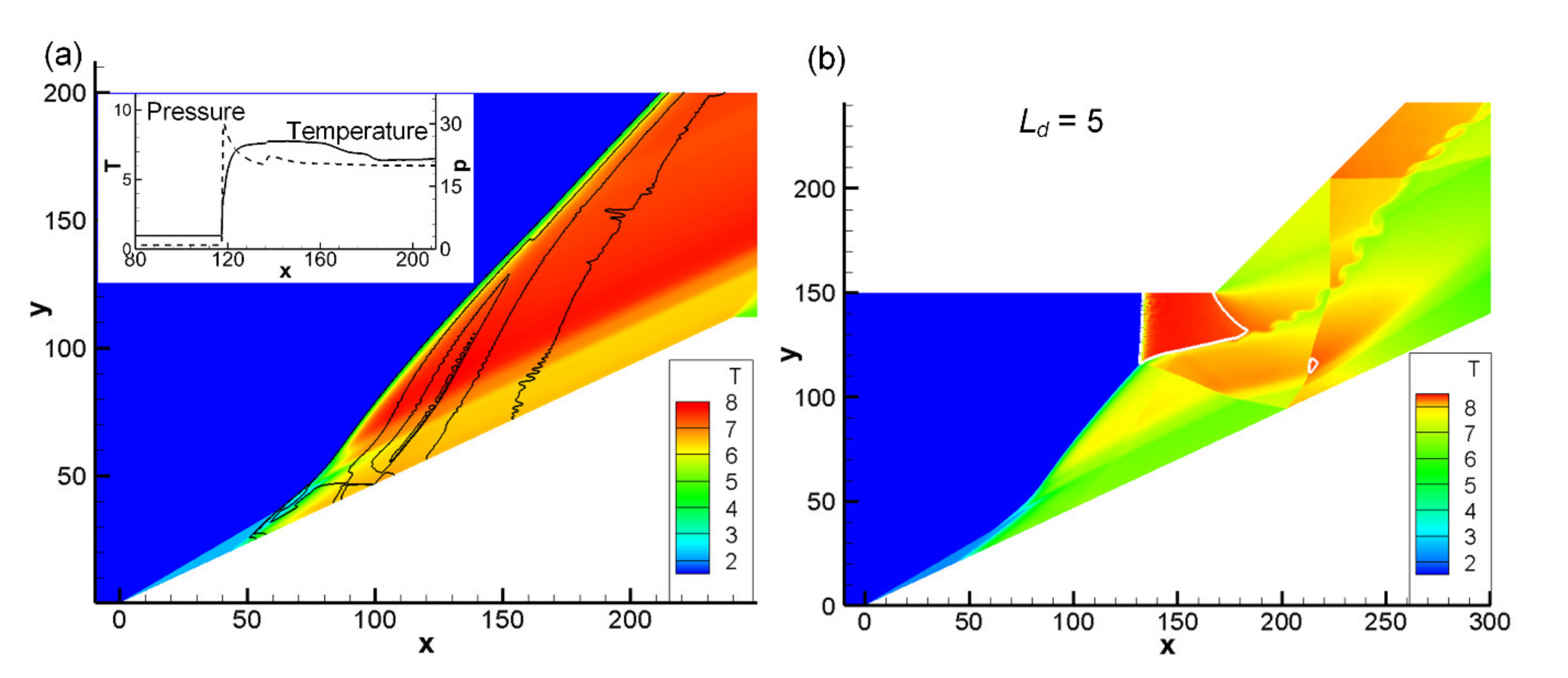
First, the wedge-induced ODWs are simulated in the free space and the upper expansion combustor, respectively. As shown in Figure 2a, the original ODW without upper wall is a typical structure with a smooth transition from an oblique shock wave (OSW) to an ODW. When we consider the upper wall, which deflects outward after the original surface, a Mach reflection zone arises. Between the Mach stem and the expansion wave, there is a subsonic zone observed, as shown by white curve in Figure 2b. At the connection point of the ODW surface and Mach stem, a transverse shock extends downstream and reflects on the wedge. From the connection point, a slip line extends downstream which becomes unstable and induces vortex. Moreover, there is an interaction of slip line and second reflection of the wedge downstream.
Based on the stable wave complex above, an unstable one arises by increasing the distance between the deflected point and the original ODW surface (Ld) as shown in Figure 3.
Four sub-frames are plotted to display the evolution of unstable structures. As denoted by the time instant, the Mach stem is generated at the early stage and then travels upstream that make a similar wave complex like the above stable case. Nevertheless, the flow field then is not stationary, leading to the variation of wave locations. The second reflection of the wedge induced a new subsonic zone and gradually connected the rear boundary of the subsonic zone which also is extending downstream. The connection leads to the combination of two subsonic zones, and the wave complex becomes unstable that triggers the overall thermal choking of flow fields.
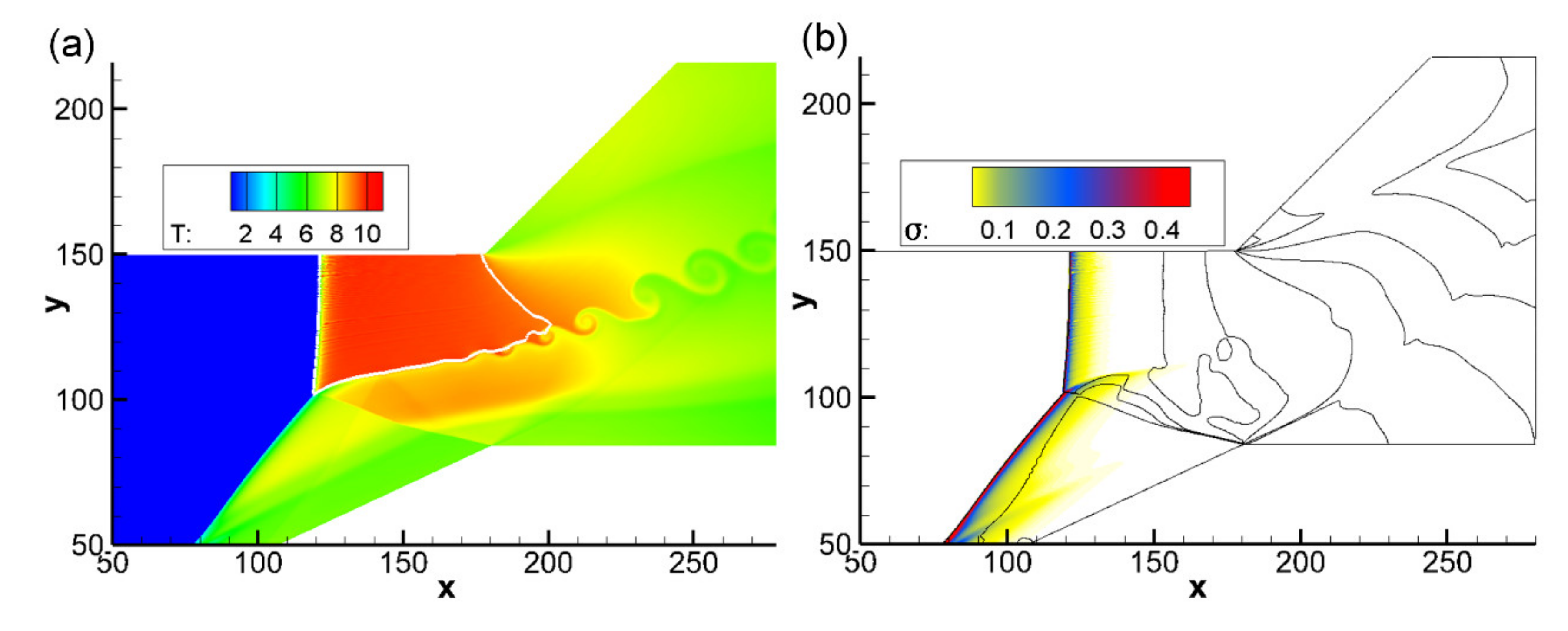
To suppress the process of thermal choking and stabilize the ODW surface, the cowl-induced expansion wave is introduced, which is specified by the corner location (Lw) and the deflection angle (θw′). A series of flow fields are simulated by adjusting Lw in a decreasing manner with a fixed deflection angle of θw = 0, and we observe there is a boundary value that can stop the upstream movement of Mach stem. Figure 4 shows the typical re-stabilized structures corresponding to M0 = 7.0, Ld = 15. As shown in Figure 4a, when the flow field becomes stable again, the reflection wave happens to act on the expansion corner, and the corresponding Lw value is about 180. The secondary reflection wave of the low wall is weakened so that it no longer affects the subsonic zone. By the effect of cowl-induced expansion wave, the downstream wave complex system becomes simple, and the heat release mainly occurs near the back of ODW and Mach stem surface. When the reflection wave acts before the expansion corner, i.e., Lw is set large than 180, an unstable evolution will still occur despite the existence of the expansion wave.
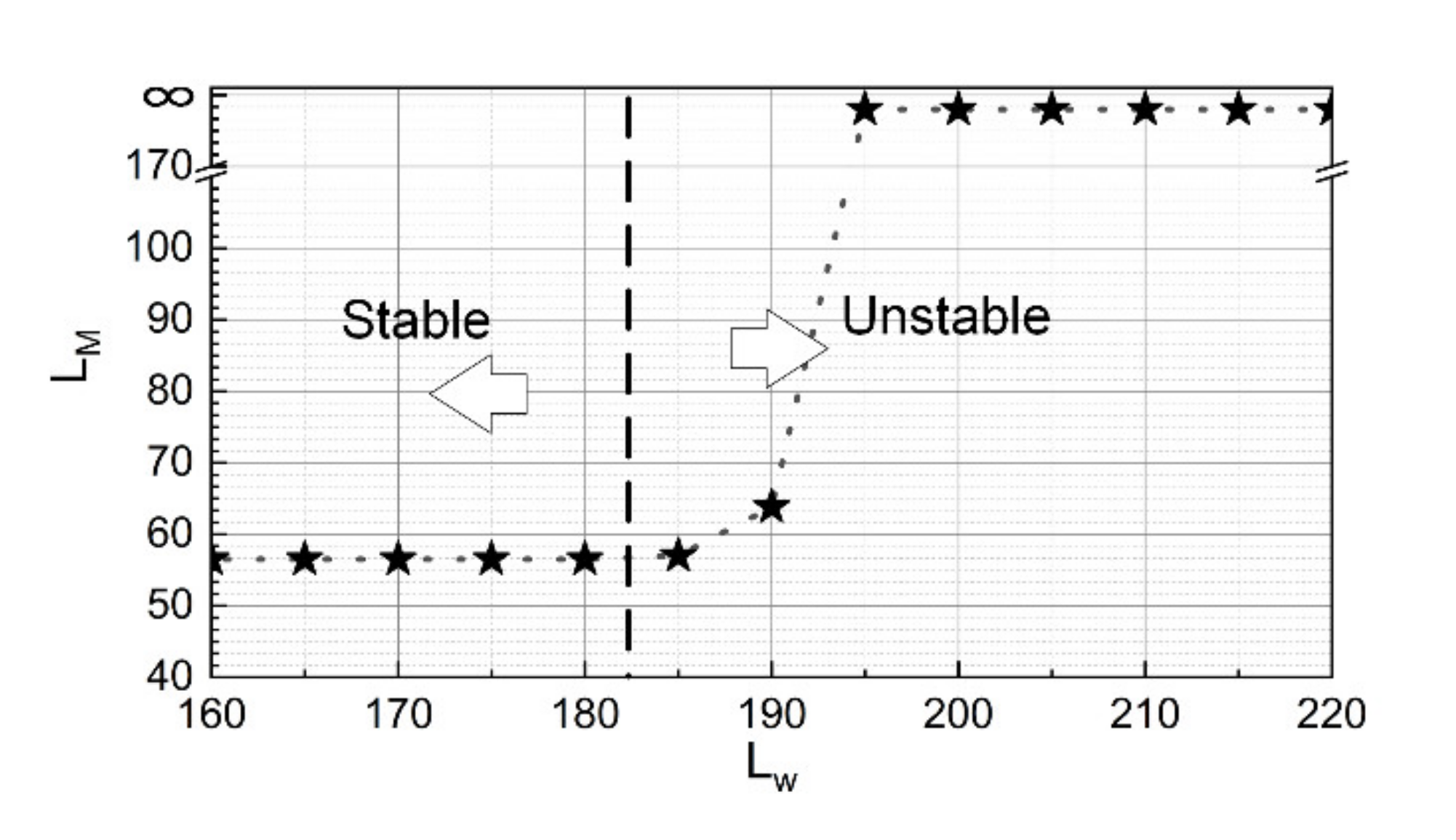
The sensitivity of Lw for the flow field is analyzed by examining the Mach stem position at the same instant, and the results are shown in Figure 5. Lw is changed in a range of 160 to 200 with an interval of 5, and the instant is chosen when the Mach stem was about to lose stability for the first unstable case (Lw = 185). In this study, LM is defined by the length of the post-stem subsonic zone, starting from the Mach stem to the expansion corner along the upper wall. With a large Lw, the Mach stem travels upstream and does not stop due to the thermal choking, so LM approaches infinity for unstable cases. However, it could be observed that with a Lw small enough, LM approaches about 57, and the length is not sensitive to Lw. This indicates that the Mach stem position is fixed in the same when the reflection wave acts after the expansion corner. The introduction of cowl-induced expansion effectively prevents the occurrence of thermal choking and its location will not change the stable ODW structure, which is a good thing for the combustor design.
The wave complex stability depends on resolving the triple point and the Mach stem. Therefore, the resolution studies were performed for the two typical cases of Ld = 5, Lw = ∞ and Ld = 15, Lw = 180 respectively. The two cases respectively represent the stability of the upper wall-induced expansion and the cowl-induced expansion, as shown in Figure 2b and Figure 4. The wave structures on two grid size scales (dx = 0.20 and dx = 0.15) are compared in Figure 6, and to distinguish the effects of grid resolution for the triple point and the Mach stem, the, we quantitatively compare the temperature and pressure along y = 125 in Figure 7.
In Figure 6 and Figure 7, the black solid lines show the results for the grid length scale dx = 0.2, and the dotted lines show those for dx = 0.15. For both cases, the triple point and the Mach stem positions keep in the same positions, and except for the slight discrepancy in the vortex position of the downstream slip line, the difference in the overall wave structure is almost negligible. Considering the vortex rolling should be attributed to the Kelvin–Helmholtz instability (KHI) of the slip line, this discrepancy does not affect the overall ODW dynamics. The curve of pressure and temperature in Figure 7 show again good agreement, therefore, the chosen grid size is sufficient to reveal the global structures for the purpose of this work.
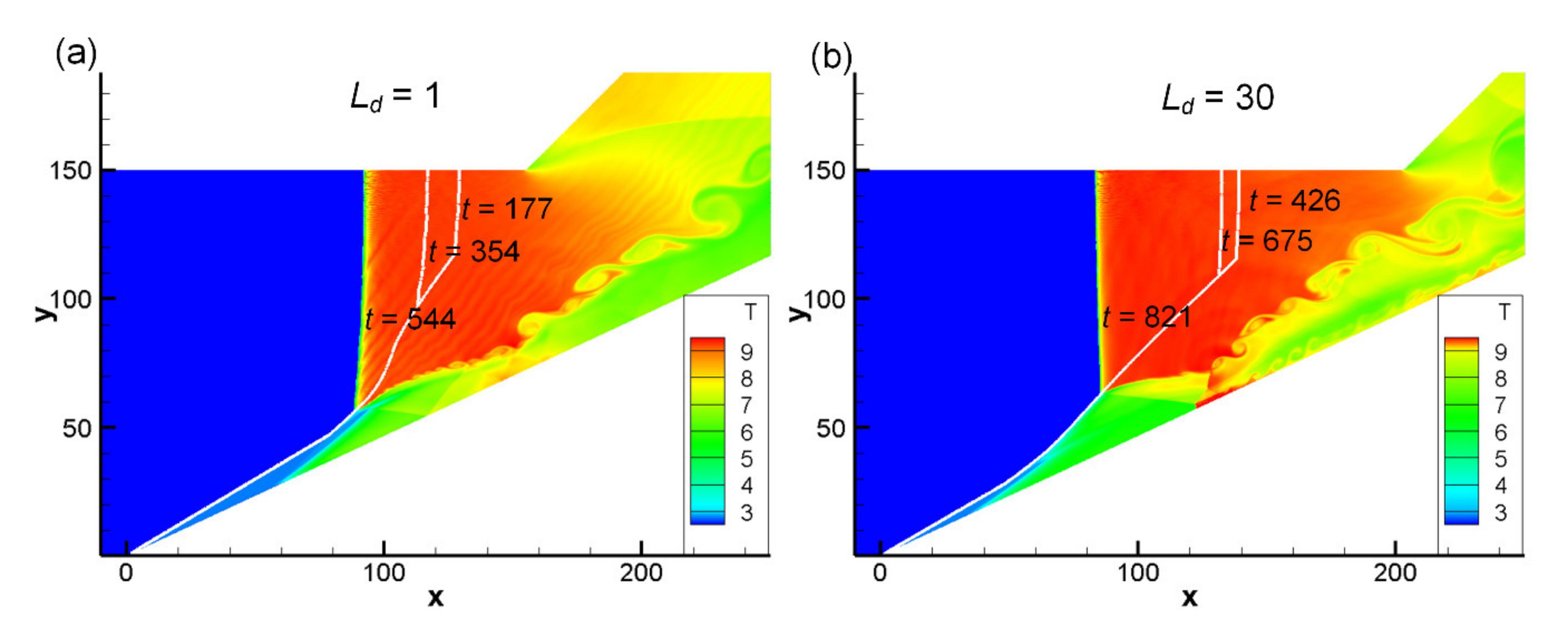
The unstable ODWs for M0 = 6.5 and M0 = 7.5 are also investigated, and the results show a similar thermal choking evolution. As shown in Figure 8, the detonation surface at different time is outlined by the white lines. The Mach stem is first formed by the reflection of original ODW on upper wall and then moves upstream over time without stopping. Given Ld = 1 for M0 = 6.5, an unstable process appears, but the corresponding Ld length for M0 = 7.5 requires to be 30. It can be concluded that the instability characteristics are the same, though the Ld length at which instability occurs increases with the Mach number. The moving Mach stem can also be stopped by the adding of cowl-induced expansion, and Figure 9 shows the typical re-stabilized flow fields of the two Mach numbers. Compared with the stable ODW in Figure 4, i.e., the case of M0 = 7.0 discussed before, both the aera and the temperature of subsonic zone increase with the Mach number, but the main flow features are basically unchanged that the secondary reflection wave of the wall cannot disturb the upstream subsonic zone.
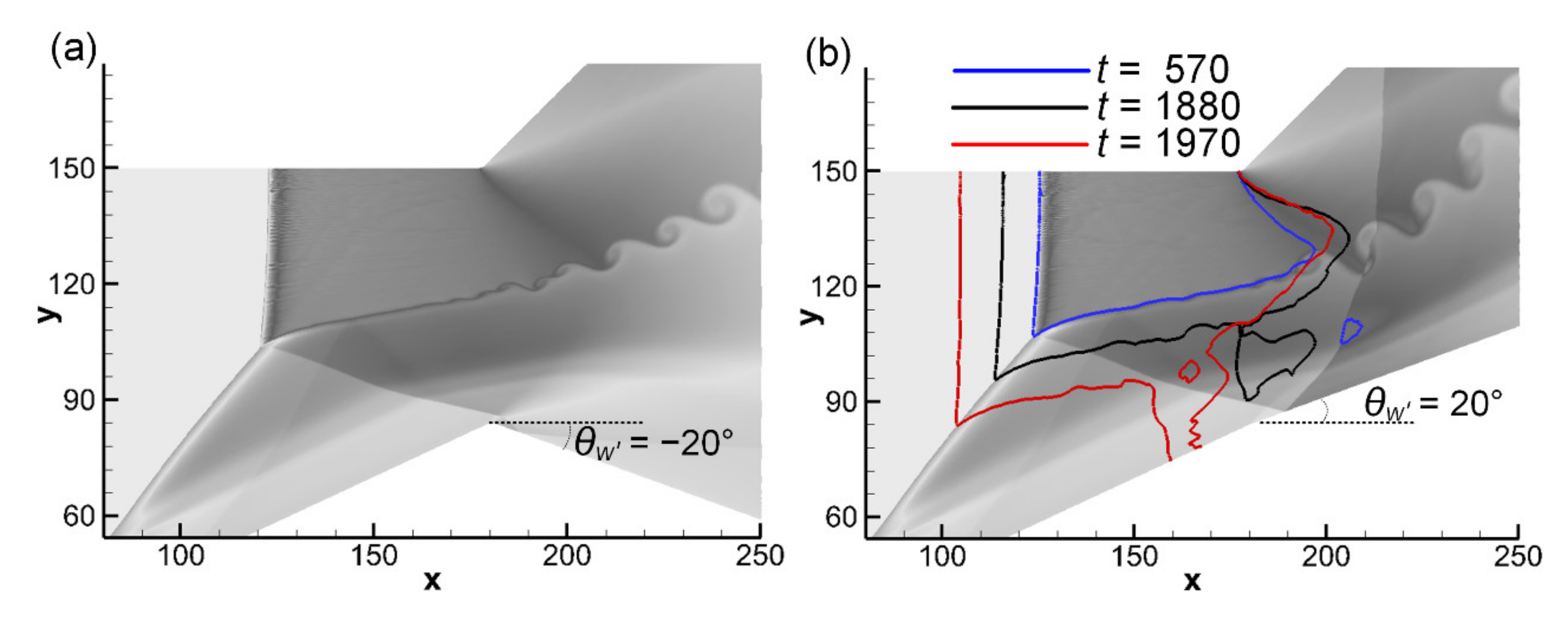
The effect of lower deflection angle (θw’) is examined based on the stable cases of M0 = 7.0. θw’ is changed in a range of −20° to 20° with an interval of 5°, and the unstable ODW arises again when θw’ increases to 20° in Figure 10b. For the stable ODW complex, it can be seen from the comparison of Figure 4 and Figure 10a that the secondary reflection of the lower wall weakens due to the extending of expansion angle. The downstream wave complex remains fixed, therefore the change of θw’ will not change the Mach stem position and the corresponding structure. As the lower expansion wall changes upward, the secondary reflection wave strengthens and deflects upstream. If the wave acts on the subsonic zone, instability will happen. To analyze the unstable ODW complex, the sonic lines at different time are shown in Figure 10b. For the unstable ODW complex, as denoted by the time instant, the early-stage flow field at t = 570 has a similar wave complex like the steady case of Figure 10a. Nevertheless, the Mach stem then is not stationary, and the subsonic zone extends downstream. The secondary reflection wave also induces a subsonic zone and connects with the upper one at t = 1880. The connection leads to the combination and expanding of two zones, and travels upstream continuously, triggering the unstable wave complex.
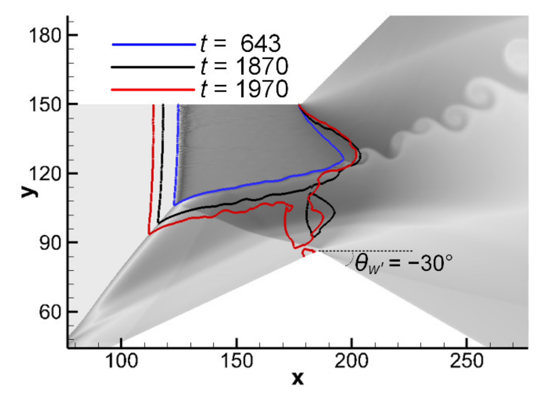
As mentioned above in Figure 5, the ODW structure becomes unstable when Lw increases to 185 with the horizontal deflection wall (θw′ = 0). We try to get the stable ODW structure of Lw = 185 by expanding θw′ to −30° (Figure 11), but the trail does not success finally. As shown by the flow dynamics in Figure 9, the combination of the two subsonic zones also happens, so the expanding of expansion angle cannot suppress the process of thermal choking. From the viewpoint of convergent-divergent flow, these cases could be explained by the hypothesis of one-dimensional isentropic: the convergence divergence ratios not yet reach the limit of the thermal choking. Therefore, the unstable evolution is controlled by the subsonic zone and the behavior of secondary reflection wave.

4. Conclusions

The wave dynamic features and the unstability rules of the cowl-induced expansion for the ODW reflection before expansion corner are investigated in this study. For the ODW reflection of only upper-side expansion, a Mach stem and the corresponding subsonic zone are produced, and the unstable mode of the wave complex has been observed. By the introduction of cowl-induced expansion, the numerical results show that the upstream movement of Mach stem can be re-stabilized for the unstable structure. The critical value of Lw is found, which is determined by the secondary reflection wave of the lower wall, while the position of stable Mach stem is not sensitive to it. By adjusting the degree of the cowl-induced expansion angle, the re-stabilized ODW shifts to unstable mode due to the influence of secondary reflection wave. However, the structure characteristics of re-stabilized ODW and the unstable process are not related with expansion angle. The unstable structures bring challenges to the application of ODW-based engines, but the numerical results suggest a feasible adjustment method and the corresponding transient phenomena deserve more attention in future work.

Author Contributions

Conceptualization, methodology, A.W. and J.S.; formal analysis, investigation, Q.W.; project administration, writing, K.W. All authors have read and agreed to the published version of the manuscript.

Funding

This research was supported by the National Natural Science Foundation of China (NSFC) (Nos. 12002041).

Data Availability Statement

Data is contained within the article.

Conflicts of Interest

The authors declare no conflict of interest.

References

  1. Ashford, S.A.; Emanuel, G. Oblique detonation wave engine performance prediction. J. Propul. Power 1996, 12, 322–327. [Google Scholar] [CrossRef]
  2. Sislian, J.P.; Schirmer, H.; Dudebout, R.; Schumacher, J. Propulsive performance of hypersonic oblique detonation wave and shock-induced combustion ramjets. J. Propul. Power 2001, 17, 599–604. [Google Scholar] [CrossRef]
  3. Urzay, J. Supersonic combustion in air-breathing propulsion systems for hypersonic flight. Annu. Rev. Fluid Mech. 2018, 50, 593–627. [Google Scholar] [CrossRef]
  4. Vanyai, T.; Bricalli, M.; Brieschenk, S.; Boyce, R.R. Scramjet performance for ideal combustion processes. Aerosp. Sci. Technol. 2018, 75, 215–226. [Google Scholar] [CrossRef]
  5. Choi, J.Y.; Kim, D.W.; Jeung, I.S.; Ma, F.; Yang, V. Cell-like structure of unstable oblique detonation wave from high-resolution numerical simulation. Proc. Combust. Inst. 2007, 31, 2473–2480. [Google Scholar] [CrossRef]
  6. Teng, H.H.; Jiang, Z.L. On the transition pattern of the oblique detonation structure. J. Fluid Mech. 2012, 713, 659–669. [Google Scholar] [CrossRef] [Green Version]
  7. Braun, E.M.; Lu, F.K.; Wilson, D.R.; Camberos, J.A. Airbreathing rotating detonation wave engine cycle analysis. Aerosp. Sci. Technol. 2013, 27, 201–208. [Google Scholar] [CrossRef] [Green Version]
  8. Viguier, C.; Figueira Da Silva, L.F.; Desbordes, D.; Deshaies, B. Onset of oblique detonation waves: Comparison between experimental and numerical results for hydrogen-air mixtures. Symp. (Int.) Combust. 1996, 26, 3023–3031. [Google Scholar] [CrossRef]
  9. Verreault, J.; Higgins, A.J.; Stowe, R.A. Formation of transverse waves in oblique detonations. Proc. Combust. Inst. 2013, 34, 1913–1920. [Google Scholar] [CrossRef]
  10. Yang, P.; Ng, H.D.; Teng, H. Unsteady dynamics of wedge-induced oblique detonations under periodic inflows. Phys. Fluids 2021, 33, 016107. [Google Scholar] [CrossRef]
  11. Bian, J.; Zhou, L.; Teng, H. Structural and thermal analysis on oblique detonation influenced by different forebody compressions in hydrogen-air mixtures. Fuel 2021, 286, 119458. [Google Scholar] [CrossRef]
  12. Yang, P.; Teng, H.H.; Jiang, Z.L.; Ng, H.D. Effects of inflow Mach number on oblique detonation initiation with a two-step induction-reaction kinetic model. Combust. Flame 2018, 193, 246–256. [Google Scholar] [CrossRef] [Green Version]
  13. Yu, M.; Miao, S. Initiation characteristics of wedge-induced oblique detonation waves in turbulence flows. Acta Astronaut. 2018, 147, 195–204. [Google Scholar] [CrossRef]
  14. Teng, H.; Bian, J.; Zhou, L.; Zhang, Y. A numerical investigation of oblique detonation waves in hydrogen-air mixtures at low mach numbers. Int. J. Hydrog. Energy 2021, 46, 10984–10994. [Google Scholar] [CrossRef]
  15. Iwata, K.; Nakaya, S.; Tsue, M. Wedge-stabilized oblique detonation in an inhomogeneous hydrogen-air mixture. Proc. Combust. Inst. 2017, 36, 2761–2769. [Google Scholar] [CrossRef]
  16. Teng, H.; Tian, C.; Zhang, Y.; Zhou, L.; Ng, H.D. Morphology of oblique detonation waves in a stoichiometric hydrogen–air mixture. J. Fluid Mech. 2021, 913, A1. [Google Scholar] [CrossRef]
  17. Pratt, D.T.; Humphrey, J.W.; Glenn, D.E. Morphology of standing oblique detonation waves. J. Propul. Power 1991, 7, 837–845. [Google Scholar] [CrossRef]
  18. Li, C.; Kailasanath, K.; Oran, E.S. Detonation structures behind oblique shocks. Phys. Fluids 1994, 6, 1600–1611. [Google Scholar] [CrossRef]
  19. Teng, H.H.; Jiang, Z.L.; Ng, H.D. Numerical study on unstable surfaces of oblique detonations. J. Fluid Mech. 2014, 744, 111–128. [Google Scholar] [CrossRef] [Green Version]
  20. Teng, H.; Ng, H.D.; Kang, L.; Luo, C.; Jiang, Z. Evolution of cellular structures on oblique detonation surfaces. Combust. Flame 2015, 162, 470–477. [Google Scholar] [CrossRef] [Green Version]
  21. Schultz, E.; Knowlen, C.; Bruckner, A.P. Starting Envelope of the Subdetonative Ram Accelerator. J. Propul. Power 2000, 16, 1040–1052. [Google Scholar] [CrossRef]
  22. Bachman, C.L.; Goodwin, G.B. Ignition criteria and the effect of boundary layers on wedge-stabilized oblique detonation waves. Combust. Flame 2021, 223, 271–283. [Google Scholar] [CrossRef]
  23. Wang, K.; Teng, H.; Yang, P.; Ng, H.D. Numerical investigation of flow structures resulting from the interaction between an oblique detonation wave and an upper expansion corner. J. Fluid Mech. 2020, 903, A28. [Google Scholar] [CrossRef]
  24. Wang, K.; Zhang, Z.; Yang, P.; Teng, H. Numerical study on reflection of an oblique detonation wave on an outward turning wall. Phys. Fluids 2020, 32, 046101. [Google Scholar]
  25. Wang, K.; Yang, P.; Teng, H. Steadiness of wave complex induced by oblique detonation wave reflection before an expansion corner. Aerosp. Sci. Technol. 2021, 112, 106592. [Google Scholar] [CrossRef]
  26. Bhattrai, B.; Tang, H. Formation of near-Chapman–Jouguet oblique detonation wave over a dual-angle ramp. Aerosp. Sci. Technol. 2017, 63, 1–8. [Google Scholar] [CrossRef]
  27. Choi, J.Y.; Shin, E.J.; Jeung, I.S. Unstable combustion induced by oblique shock waves at the non-attaching condition of the oblique detonation wave. Proc. Combust. Inst. 2009, 32, 2387–2396. [Google Scholar] [CrossRef]
  28. Xiang, G.X.; Gao, X.; Tang, W.J.; Jie, X.Z.; Huang, X. Numerical study on transition structures of oblique detonations with expansion wave from finite-length cowl. Phys. Fluids 2020, 32, 056108. [Google Scholar] [CrossRef]
  29. Korobeinikov, V.P.; Levin, V.A.; Markov, V.V.; Chernyi, G.G. Propagation of blast waves in a combustible gas. Astronaut. Acta 1972, 17, 529–537. [Google Scholar]
  30. Ng, H.D.; Radulescu, M.I.; Higgins, A.J.; Nikiforakis, N.; Lee, J.H.S. Numerical investigation of the instability for one-dimensional Chapman-Jouguet detonations with chain-branching kinetics. Combust. Theory Model 2005, 9, 385–401. [Google Scholar] [CrossRef]
  31. Kim, K.H.; Kim, C.; Rho, O.-H. Methods for the Accurate Computations of Hypersonic Flows: I. AUSMPW+Scheme. J. Comput. Phys. 2001, 174, 38–80. [Google Scholar] [CrossRef]
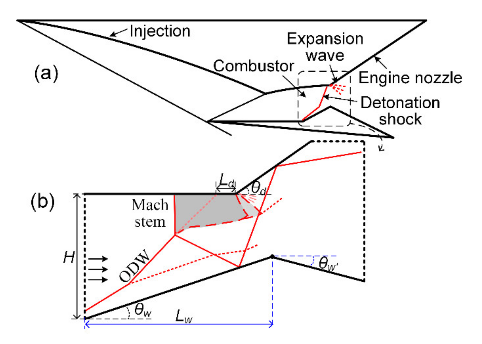
Figure 1. Schematic of oblique detonation engine (a) and wave complex (b).
Processes 09 01215 g001
Figure 2. ODW temperature fields for M0 =7.0, (a) without upper wall; (b) with upper wall and Ld = 5 (white curve denotes the sonic line).
Processes 09 01215 g002
Figure 3. Unstable ODW evolution for M0 =7.0, Ld = 15 at different instants, (a) t = 92; (b) t = 277; (c) t = 586; (d) t = 893.
Processes 09 01215 g003
Figure 4. Re-stabilized ODW structure for M0 =7.0, Ld = 15, Lw = 180 (a) temperature field with white curve denoting the sonic line; (b) heat release field with pressure contours.
Processes 09 01215 g004
Figure 5. The relation of LwLM for M0 =7.0, Ld = 15.
Processes 09 01215 g005
Figure 6. Temperature contours from different grids (a) M0 =7.0, Ld = 5, Lw = ∞; (b) M0 =7.0, Ld = 15, Lw = 180.
Processes 09 01215 g006
Figure 7. Pressure and temperature along certain lines of above two cases (a) M0 =7.0, Ld = 5, Lw = ∞; (b) M0 =7.0, Ld = 15, Lw = 180.
Processes 09 01215 g007
Figure 8. Unstable ODW evolutions (a) M0 = 6.5, Ld = 1, Lw = ∞; (b) M0 = 7.5, Ld = 30, Lw = ∞.
Processes 09 01215 g008
Figure 9. Re-stabilized ODW structures (a) M0 = 6.5, Ld = 1, Lw = 100; (b) M0 = 7.5, Ld = 30, Lw = 210.
Processes 09 01215 g009
Figure 10. Effects of lower deflection angles for M0 = 7.0, Ld = 15, Lw = 180, (a) θw’ = −20°; (b) θw’ = 20°.
Processes 09 01215 g010
Figure 11. Unstable ODW for M0 =7.0, Ld = 15, Lw = 185.
Processes 09 01215 g011
Table 1. Simulation parameters used in the following cases.
Q25
γ1.2
EI4.0Ts
ER1.0Ts
M06.5, 7.0, 7.5
θw25°
θd45°
H150
Publisher’s Note: MDPI stays neutral with regard to jurisdictional claims in published maps and institutional affiliations.