
Ripple Attenuation for Induction Motor Finite Control Set Model Predictive Torque Control Using Novel Fuzzy Adaptive Techniques


Abstract
1. Introduction
- (1)
- The novel idea that using a fuzzy adaptive PI controller to reduce the system ripples (mainly caused by the external sensors) of the FCS-MPTC method is studied. Traditionally, the fuzzy adaptive speed controller is adopted to improve the dynamics of the system, and there are few studies using it to improve the steady-state performance. On this basis, this study is comparatively pretty novel.
- (2)
- Unlike the traditional two-dimensional fuzzy adaptive PI controller, the proposed one aim to improve the steady-state performance of the system. To achieve this goal, firstly, the input scaling factor of the fuzzy controller is optimized, relying on the pre-setting speed, enlarging the variation range of input and output. Secondly, the structure of the fuzzy controller is rebuilt. In detail, both the current and previous speed errors and the error between the current and the previous speed errors (CPSE-E) are treated as the inputs to build a three-dimensional fuzzy controller. This assists in evaluating the effectiveness of the proportional and integral factors designed in the previous period and ultimately provide guidelines for generating new control parameters. What needs to be mentioned is that although the fuzzy control strategies that are achieved by using the previous states or errors were studied previously in [33,34,35]. The proposed fuzzy controller is still pretty novel considering its structure and role in suppressing the steady-state ripples of an IM. This contributes to enriching the fuzzy control theories and prompting the relevant applications.
- (3)
- Few studies incorporate the fuzzy adaptive theory into the weighting factor tuning process for an FCS-MPTC strategy. However, this paper proposes a new fuzzy adaptive weighting factor tuning strategy, whereby the inputs are torque and flux errors. By balancing the importance degree of the two variables, the torque and flux ripples are inclined to decrease.
2. Modelling for IM FCS-MPTC
3. Proposed Fuzzy Adaptive PI Controller-Based FCS-MPTC
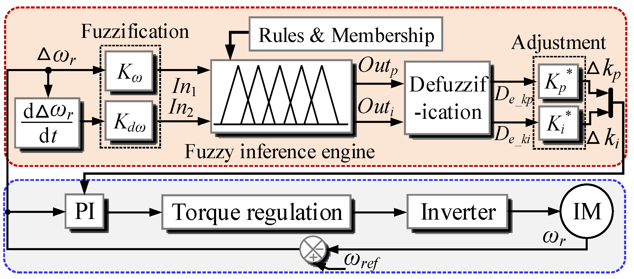
3.1. Traditional Fuzzy Adaptive PI Controller
3.2. Proposed Fuzzy Adaptive PI Controller Used for Ripple Reduction
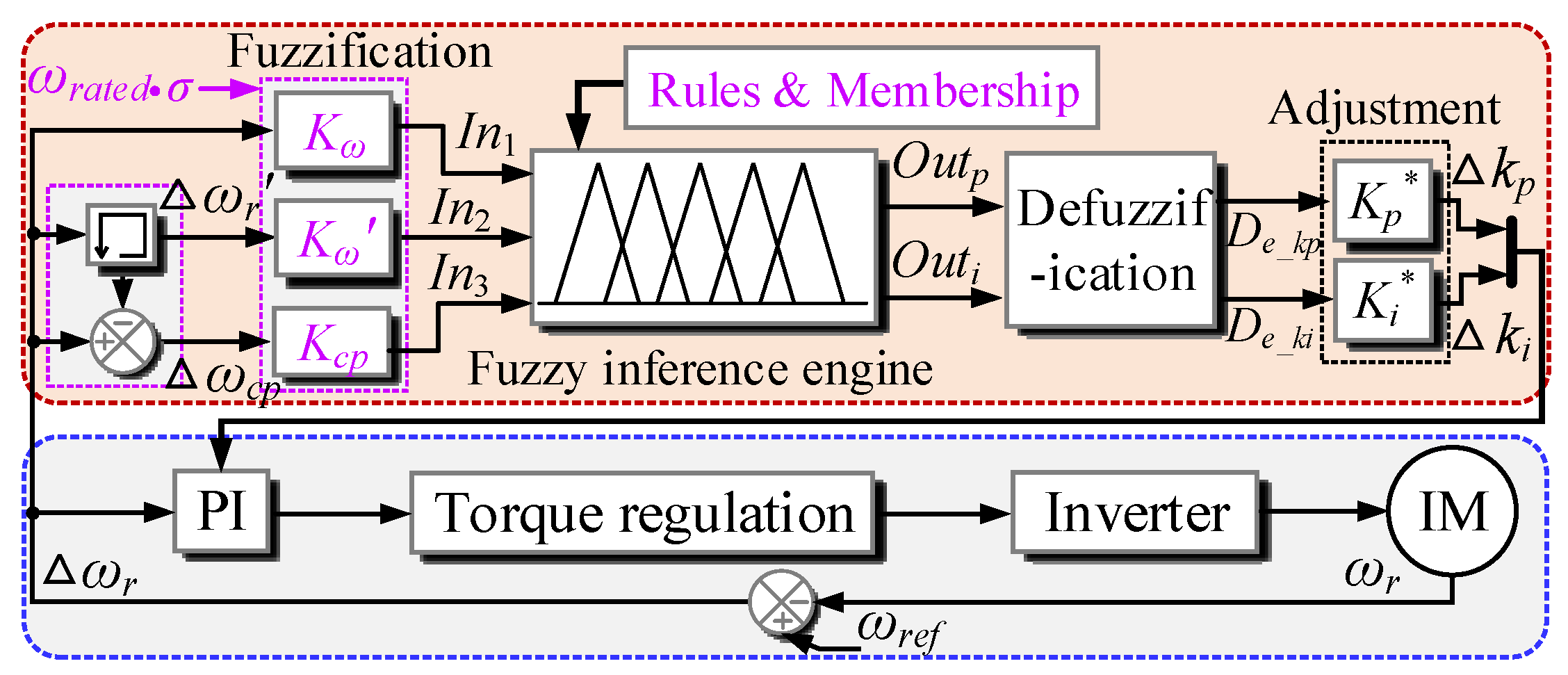
3.2.1. Explanations of Three-Dimensional Fuzzy Controller Concerning Novel Structure
3.2.2. Design of Each Fuzzy controller Component
- (a)
- Fuzzification
- (b)
- Fuzzy control rules
- When the signs of In1 and In2 are the same, if In3 indicates that the speed ripples are increasing, a negative value of Δkp and a positive value of Δki should be applied to reduce the bandwidth of the system. In this case, the system response speed drops, so that the speed ripples can be suppressed before it reaches the upper limit.
- When the signs of In1 and In2 are the same, if In3 indicates that the speed ripples are decreasing, the in-service PI controller parameters are suitable. Both the values of Δkp and Δki should be only adjusted slightly.
- When the signs of In1 and In2 are opposite, if the absolute value of In3 is large, a negative value of Δkp and a positive value of Δki are adopted to restrain the response speed of the system.
- When the signs of In1 and In2 are opposite, if the absolute value of In3 is small, the relatively smaller compensation values are generated to adjust the parameters of the PI controller. In these cases, it is not necessary to markedly adjust the controller parameters because the in-service parameter values calculated in the previous period are appropriate.
- (c)
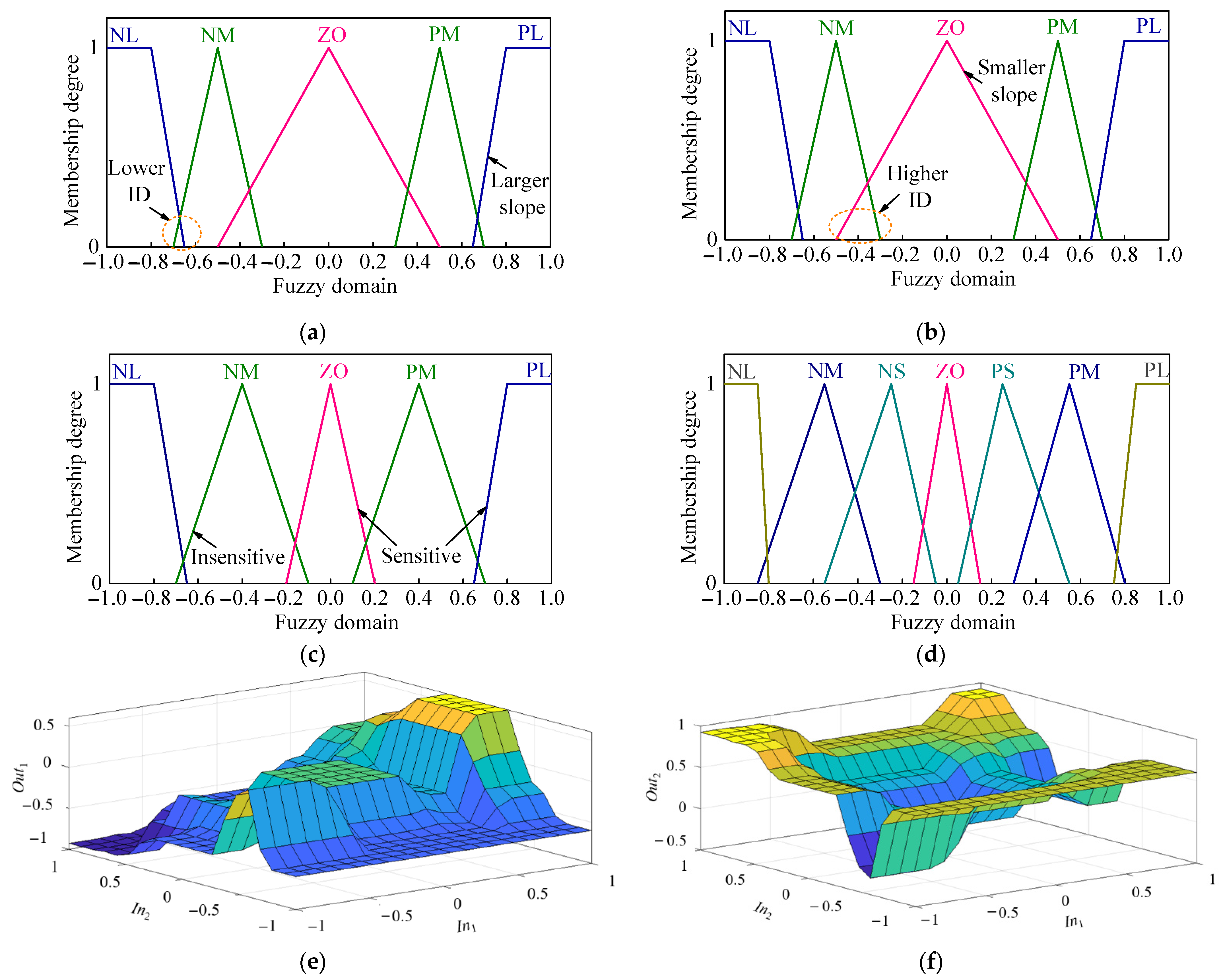
- Membership functions
- (d)
- Defuzzification
- (e)
- Adjustment
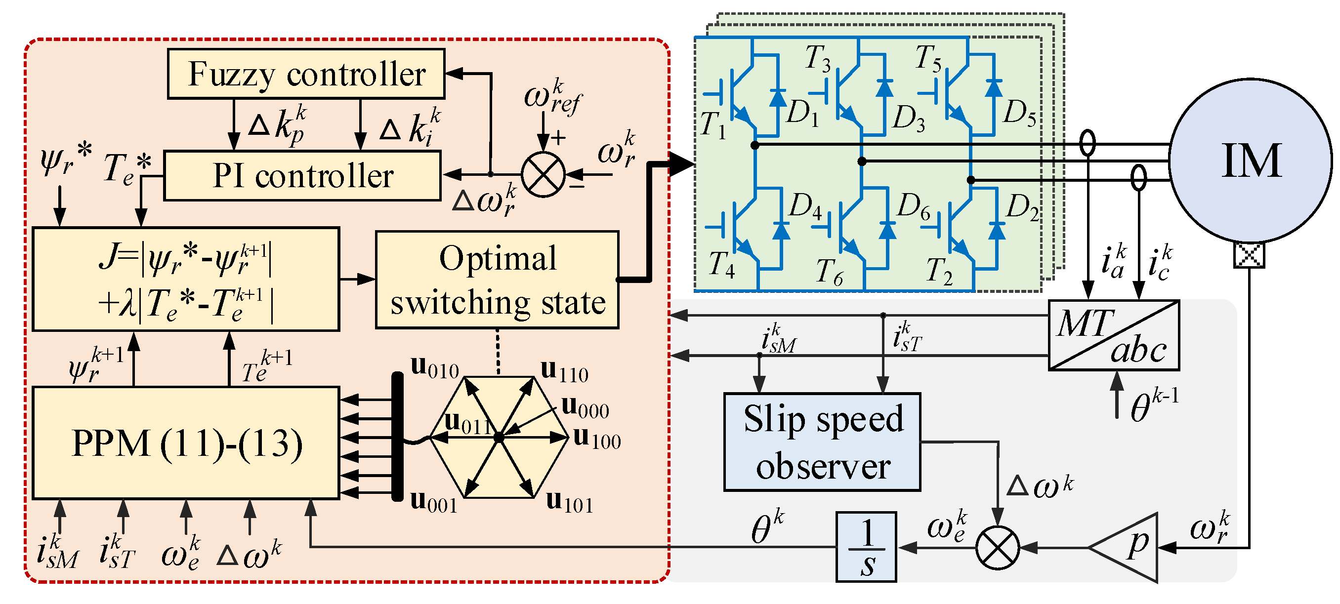
3.3. Implementation of Proposed Fuzzy Adaptive PI Controller-Based FCS-MPTC
- (a)
- Measurement: The phase currents , and rotor speed are measured by using current and speed sensors (common methods in engineering).
- (b)
- abc/MT transformation: The measured phase currents are transformed to the MT-axis currents , according to the estimated rotor flux position in the last period.
- (c)
- Observation: Use the currents , to calculate the slip speed , synchronous speed and position .
- (d)
- Calculation of compensation values: The speed error is obtained by subtracting from the reference speed , and then, the fuzzy controller is used to calculate the compensation values and .
- (e)
- Reference torque and flux generation: Use the PI controller of which parameters comply with the results in (22) to calculate the reference torque Te*, while the reference flux ψr* is given manually.
- (f)
- Prediction: Use the speed and current information to estimate the future current states , and for the candidate voltage vectors. As for a two-level inverter, a total of seven phase voltage vectors that are denoted as u000, u100, u110, u010, u011, u001, and u101 are among the alternatives,
- (g)
- Evaluation: Substitute the seven the predicted values into a traditional one-step cost function (25) and determine the optimal voltage vector and the corresponding switching states [43].
- (h)
- Actuation: Apply the optimum switching states to the drive system.
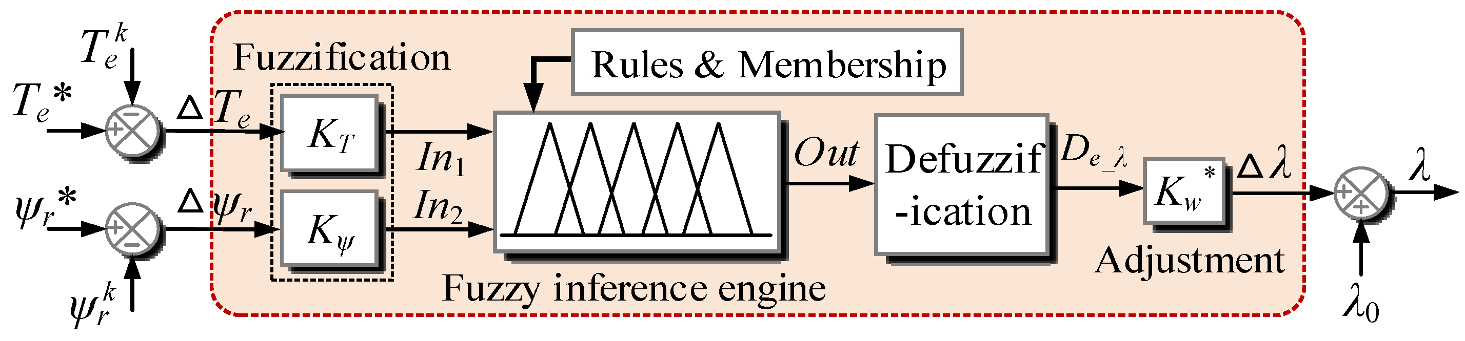
4. Novel Adaptive Weighting Factor Tuning Strategy
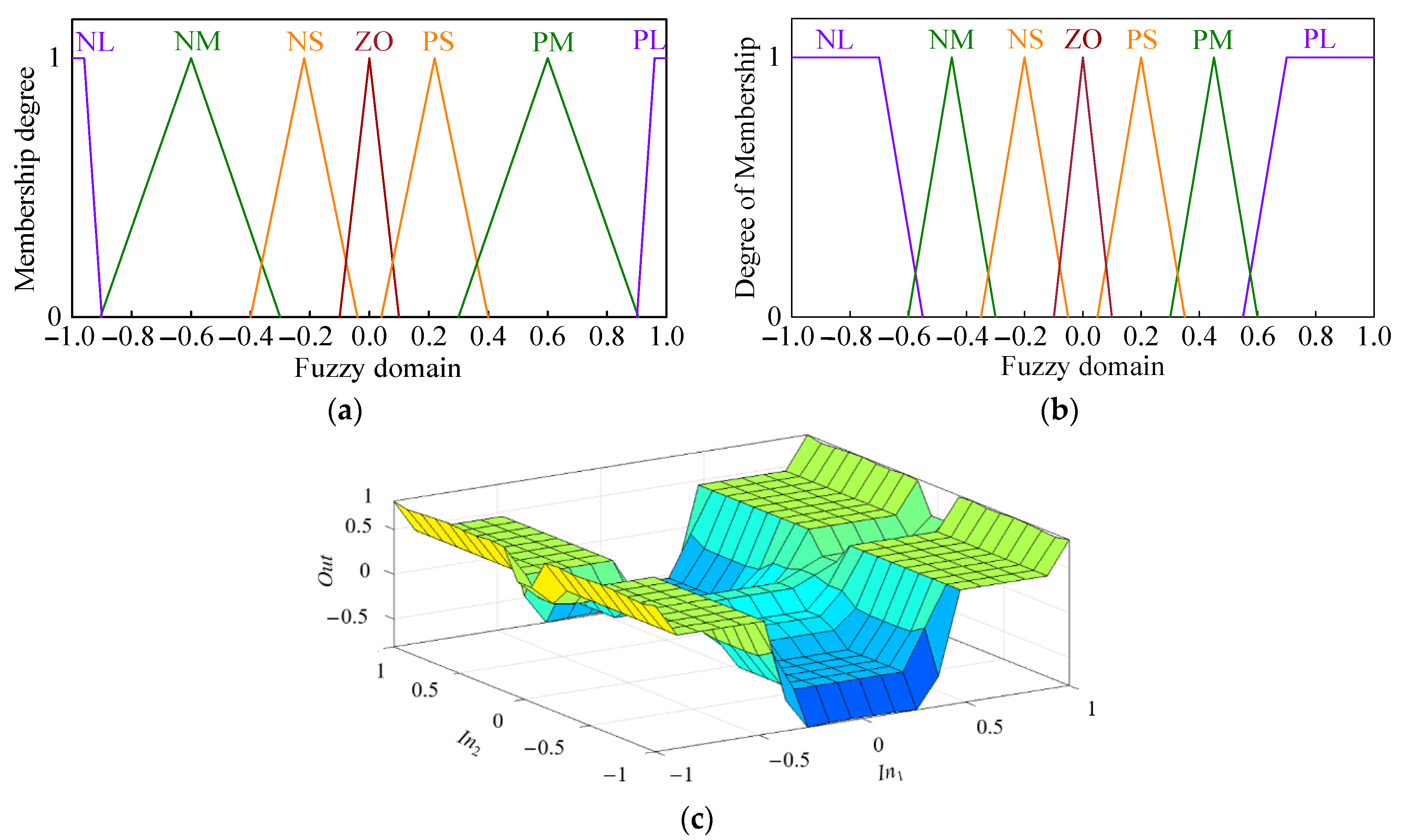
- (a)
- Fuzzification
- (b)
- Fuzzy control rules
- (1)
- When In1 is large or medium (large torque error), a large or medium positive value of Δλ is generated regardless of the magnitude of In2. In this case, the priority is to suppress the torque ripples because the torque performance is the direct output of the machine.
- (2)
- When In1 is small, the output of the fuzzy controller is determined by In2. If In2 is large, a large negative compensation value is generated to stress the importance of flux, while if In2 is small, the weighting factor does not need to be adjusted significantly.
- (c)
- Membership functions
- (d)
- Defuzzification
- (e)
- Adjustment
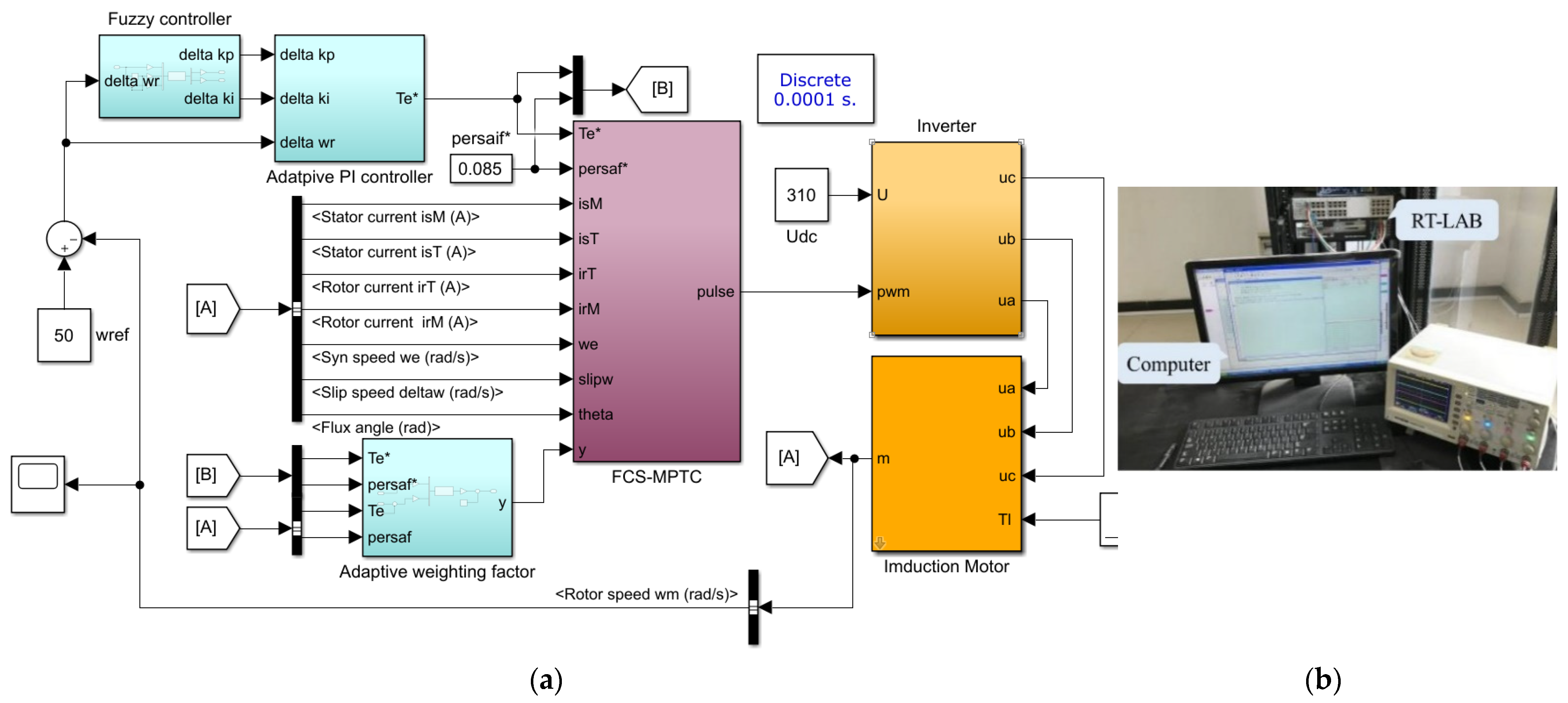
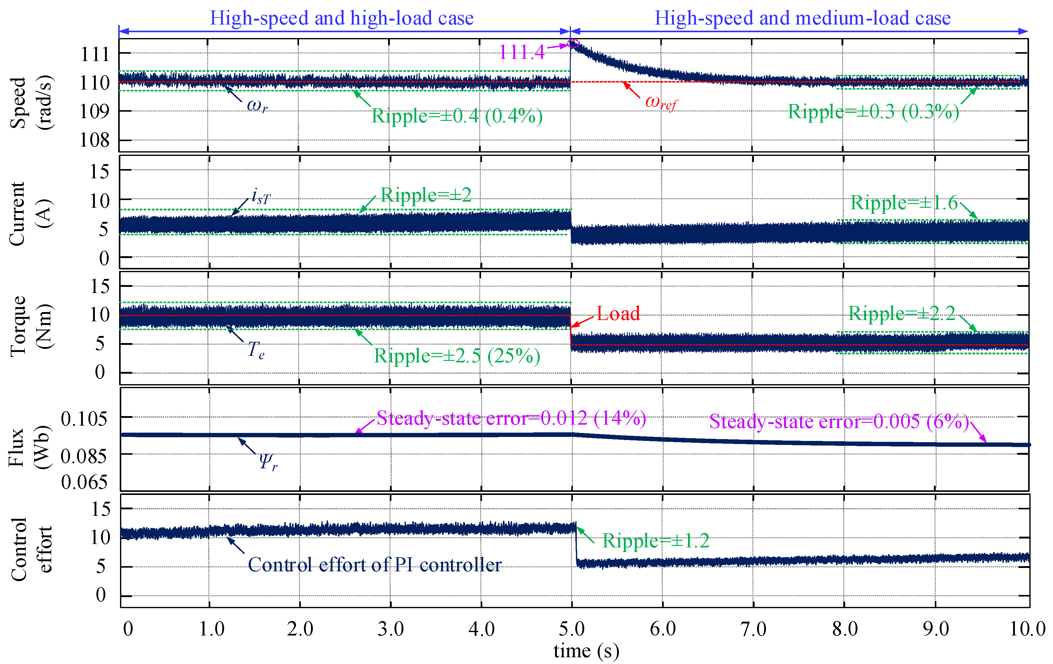
5. Simulation and Hardwar-In-Loop Testing Results
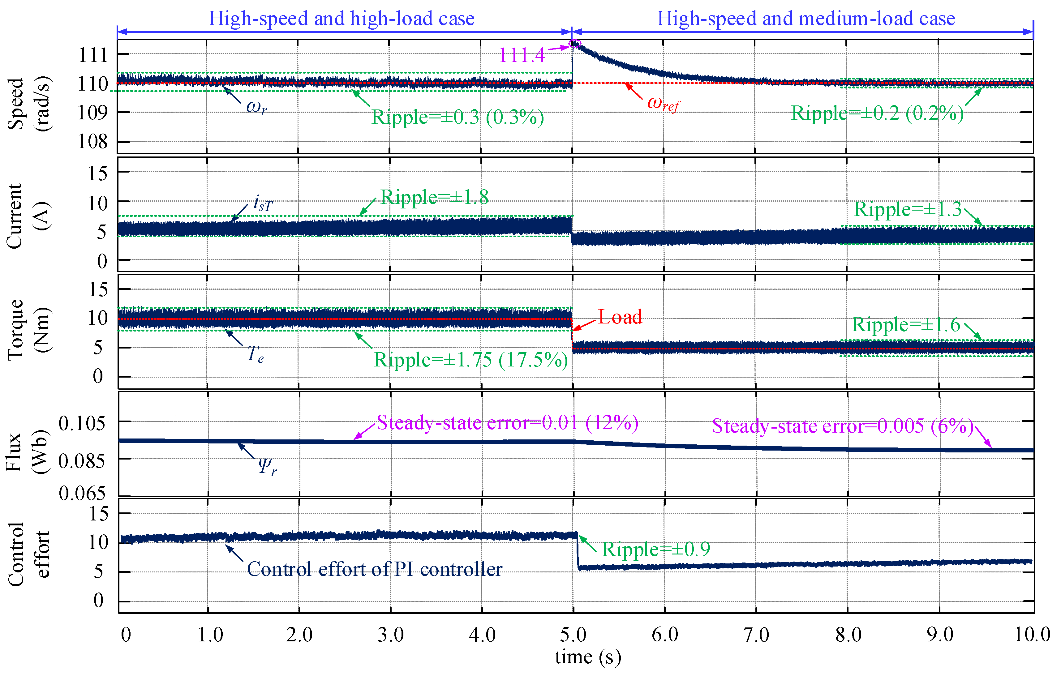
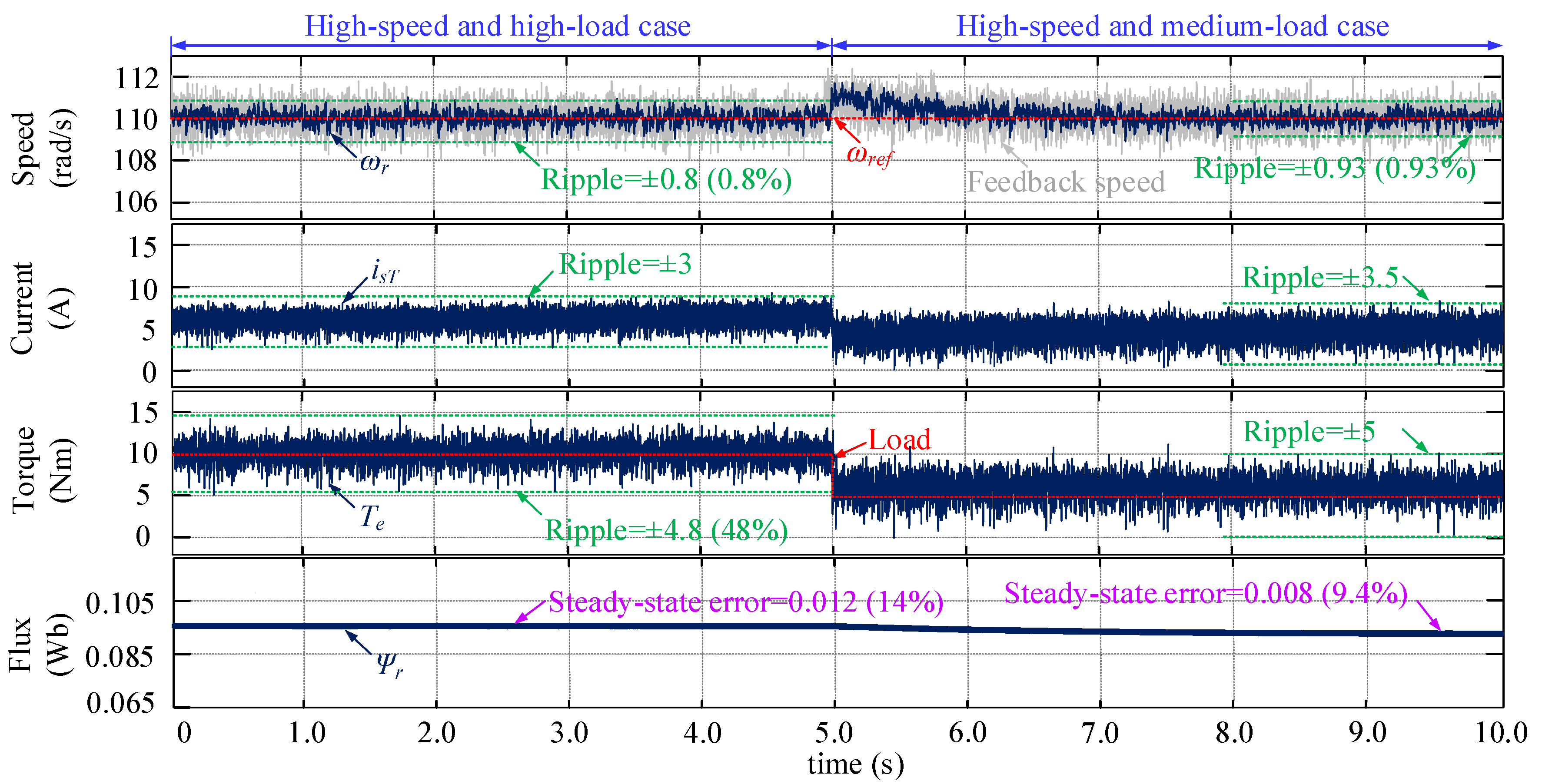
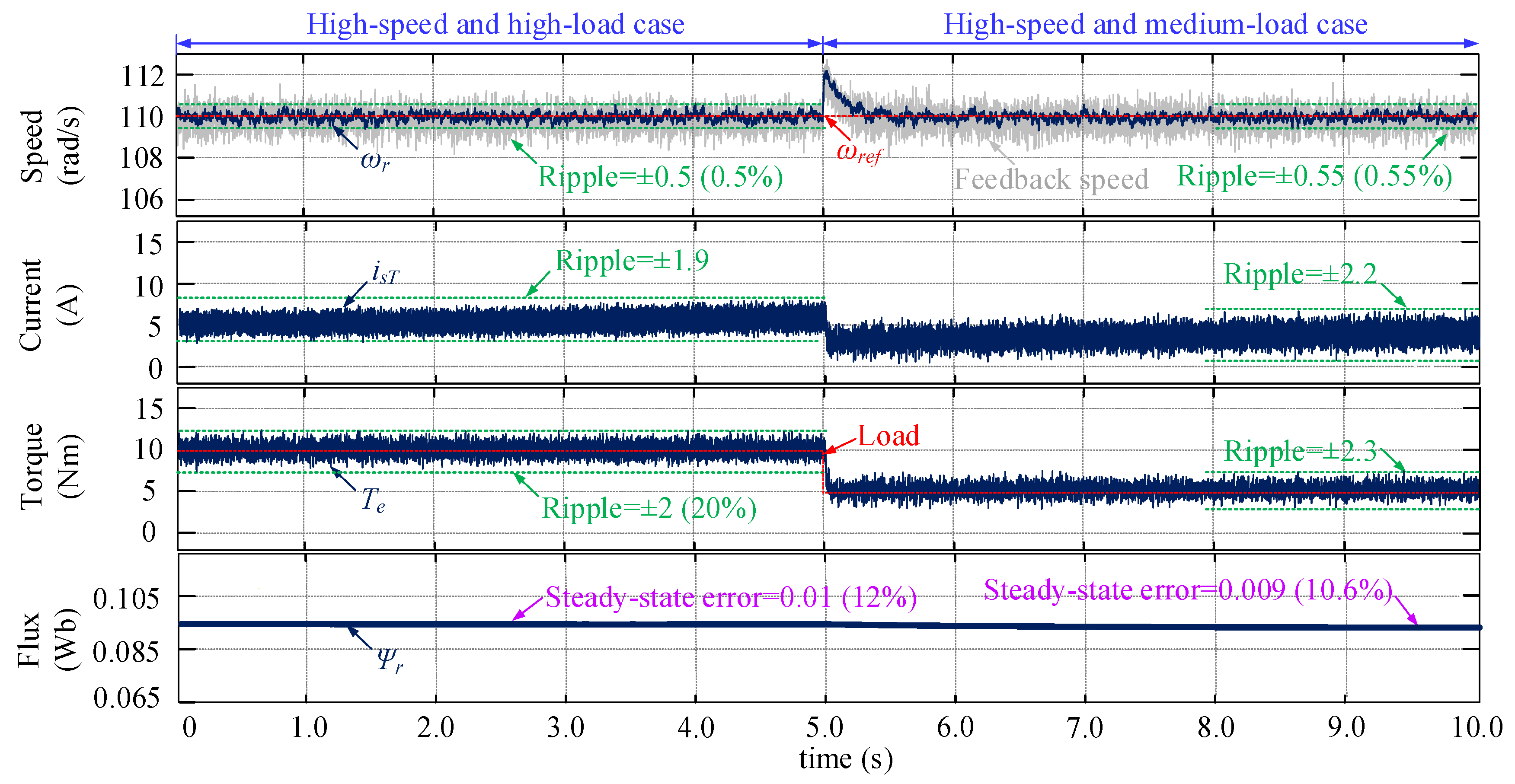
5.1. Simulation Results
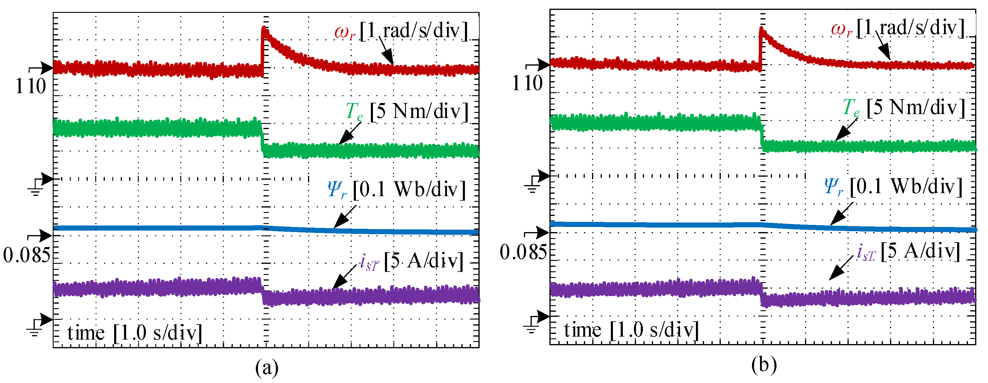
5.2. HIL Testing Results
6. Conclusions
- The PPM of the IM drives is established for achieving the FCS-MPTC algorithm. It needs to be mentioned that, in this paper, in order to calculate the rotor flux more accurately, a novel flux observer based on the numerical solution of flux differential equation is derived.
- The reasons why the traditional fuzzy adaptive speed controller contributes less in suppressing the system ripples are analyzed theoretically. On this basis, an improved three-dimensional fuzzy adaptive PI controller was developed, with a new structure and modified input scaling factors. The proposed fuzzy adaptive PI controller is suitable for ripple reduction because the bandwidth of the system becomes narrow when the speed ripples are large, eliminating the impact of the high-frequency disturbances.
- A novel weighting factor tuning strategy based on fuzzy adaptive theory was developed. It is achieved by balancing the ripples of flux and torque. The proposed weighting factor strategy is adjusted in real-time, avoiding the ripples caused by the inappropriate internal parameters.
Author Contributions
Funding
Institutional Review Board Statement
Informed Consent Statement
Conflicts of Interest
References
- Listwan, J.; Pieńkowski, K. Comparative Analysis of Control Methods with Model Reference Adaptive System Estimators of a Seven-Phase Induction Motor with Encoder Failure. Energies 2021, 14, 1147. [Google Scholar] [CrossRef]
- Gunabalan, R.; Sanjeevikumar, P.; Blaabjerg, F.; Ojo, O.; Subbiah, V. Analysis and Implementation of Parallel Connected Two-Induction Motor Single-Inverter Drive by Direct Vector Control for Industrial Application. IEEE Trans. Power Electron. 2015, 30, 6472–6475. [Google Scholar] [CrossRef]
- Xu, Q.; Cui, S.; Zhang, Q.; Song, L.; Li, X. Research on a New Accurate Thrust Control Strategy for Linear Induction Motor. IEEE Trans. Plasma Sci. 2015, 43, 1321–1325. [Google Scholar]
- Dhar, S.; Jayakumar, A.; Lavanya, R.; Kumar, M.D. Techno-economic assessment of various motors for three-wheeler E-auto rickshaw: From Indian context. Mater. Today Proc. 2021. [Google Scholar] [CrossRef]
- Wang, Z.; Chen, J.; Cheng, M.; Chau, K.T. Field-Oriented Control and Direct Torque Control for Paralleled VSIs Fed PMSM Drives with Variable Switching Frequencies. IEEE Trans. Power Electron. 2016, 31, 2417–2428. [Google Scholar] [CrossRef]
- Jain, A.K.; Ranganathan, V.T. Modeling and Field Oriented Control of Salient Pole Wound Field Synchronous Machine in Stator Flux Coordinates. IEEE Trans. Ind. Electron. 2011, 58, 960–970. [Google Scholar] [CrossRef]
- Gong, C.; Hu, Y.; Chen, G.; Wen, H.; Wang, Z.; Ni, K. A DC-Bus Capacitor Discharge Strategy for PMSM Drive System with Large Inertia and Small System Safe Current in EVs. IEEE Trans. Ind. Inform. 2019, 15, 4709–4718. [Google Scholar] [CrossRef]
- Song, S.; Xia, Z.; Fang, G.; Ma, R.; Liu, W. Phase Current Reconstruction and Control of Three-Phase Switched Reluctance Machine with Modular Power Converter Using Single DC-Link Current Sensor. IEEE Trans. Power Electron. 2018, 33, 8637–8649. [Google Scholar] [CrossRef]
- Fu, X.; Li, S. A Novel Neural Network Vector Control Technique for Induction Motor Drive. IEEE Trans. Energy Convers. 2015, 30, 1428–1437. [Google Scholar] [CrossRef]
- Wróbel, K.; Serkies, P.; Szabat, K. Model Predictive Base Direct Speed Control of Induction Motor Drive—Continuous and Finite Set Approaches. Energies 2020, 13, 1193. [Google Scholar] [CrossRef]
- Ahmed, A.A.; Koh, B.K.; Lee, Y.I. A Comparison of Finite Control Set and Continuous Control Set Model Predictive Control Schemes for Speed Control of Induction Motors. IEEE Trans. Ind. Inform. 2018, 14, 1334–1346. [Google Scholar] [CrossRef]
- Yan, L.; Dou, M.; Hua, Z.; Zhang, H.; Yang, J. Robustness Improvement of FCS-MPTC for Induction Machine Drives Using Disturbance Feedforward Compensation Technique. IEEE Trans. Power Electron. 2019, 34, 2874–2886. [Google Scholar] [CrossRef]
- Gong, C.; Hu, Y.; Ni, K.; Liu, J.; Gao, J. SM Load Torque Observer-Based FCS-MPDSC with Single Prediction Horizon for High Dynamics of Surface-Mounted PMSM. IEEE Tran. Power Electron. 2020, 35, 20–24. [Google Scholar] [CrossRef]
- Jun, E.S.; Park, S.Y.; Kwak, S. Model Predictive Current Control Method with Improved Performances for Three-Phase Voltage Source Inverters. Electronics 2019, 8, 625. [Google Scholar] [CrossRef]
- Gong, C.; Hu, Y.; Gao, J.; Wang, Y.; Yan, L. An Improved Delay-Suppressed Sliding-Mode Observer for Sensorless Vector-Controlled PMSM. IEEE Trans. Ind. Electron. 2020, 67, 5913–5923. [Google Scholar] [CrossRef]
- Zhang, Z.; Fang, H.; Gao, F.; Rodríguez, J.; Kennel, R. Multiple-Vector Model Predictive Power Control for Grid-Tied Wind Turbine System with Enhanced Steady-State Control Performance. IEEE Trans. Ind. Electron. 2017, 64, 6287–6298. [Google Scholar] [CrossRef]
- Liu, Z.; Zhao, Y. Robust Perturbation Observer-based Finite Control Set Model Predictive Current Control for SPMSM Considering Parameter Mismatch. Energies 2019, 12, 3711. [Google Scholar] [CrossRef]
- Zhang, Y.; Yang, H. Model-Predictive Flux Control of Induction Motor Drives with Switching Instant Optimization. IEEE Trans. Energy Convers. 2015, 30, 1113–1122. [Google Scholar] [CrossRef]
- Mamdouh, M.; Abido, M.; Hamouz, Z. Weighting Factor Selection Techniques for Predictive Torque Control of Induction Motor Drives: A Comparison Study. Arab. J. Sci. Eng. 2018, 43, 433–445. [Google Scholar] [CrossRef]
- Arahal, M.R.; Barrero, F.; Duran, M.J.; Ortega, M.G.; Martin, C. Trade-offs Analysis in Predictive Current Control of Multi-Phase Induction Machines. Control Eng. Pract. 2018, 81, 105–113. [Google Scholar] [CrossRef]
- Alamir, M. A State-Dependent Updating Period for Certified Real-Time Model Predictive Control. IEEE Tran. Automat. Contr. 2017, 62, 2464–2469. [Google Scholar] [CrossRef]
- Gao, J.; Gong, C.; Li, W.; Liu, J. Novel Compensation Strategy for Calculation Delay of Finite Control Set Model Predictive Current Control in PMSM. IEEE Trans. Ind. Electron. 2020, 67, 5816–5819. [Google Scholar] [CrossRef]
- Li, H.; Lin, J.; Lu, Z. Three Vectors Model Predictive Torque Control without Weighting Factor Based on Electromagnetic Torque Feedback Compensation. Energies 2019, 12, 1393. [Google Scholar] [CrossRef]
- Li, Z.; Yuan, Y.; Ke, F.; He, W.; Su, C. Robust Vision-Based Tube Model Predictive Control of Multiple Mobile Robots for Leader–Follower Formation. IEEE Tran. Ind. Electron. 2020, 67, 3096–3106. [Google Scholar] [CrossRef]
- Yang, Y.; Wen, H.; Fan, M.; Xie, M.; Chen, R. Fast Finite-Switching-State Model Predictive Control Method without Weighting Factors for T-Type Three-Level Three-Phase Inverters. IEEE Trans. Ind. Inform. 2019, 15, 1298–1310. [Google Scholar] [CrossRef]
- Zhang, X.; Hou, B.; Mei, Y. Deadbeat Predictive Current Control of Permanent-Magnet Synchronous Motors with Stator Current and Disturbance Observer. IEEE Trans. Power Electron. 2017, 32, 3818–3834. [Google Scholar] [CrossRef]
- Arshad, M.H.; Abido, M.A.; Salem, A.; Elsayed, A.H. Weighting Factors Optimization of Model Predictive Torque Control of Induction Motor Using NSGA-II with TOPSIS Decision Making. IEEE Access 2019, 7, 177595–177606. [Google Scholar] [CrossRef]
- Rojas, C.A.; Rodriguez, J.; Villarroel, F.; Espinoza, J.R.; Silva, C.A.; Trincado, M. Predictive Torque and Flux Control without Weighting Factors. IEEE Trans. Ind. Electron. 2013, 60, 681–690. [Google Scholar] [CrossRef]
- Wang, J.; Wang, F.; Zhang, Z.; Li, S.; Rodríguez, J. Design and Implementation of Disturbance Compensation-Based Enhanced Robust Finite Control Set Predictive Torque Control for Induction Motor Systems. IEEE Trans. Ind. Inform. 2017, 13, 2645–2656. [Google Scholar] [CrossRef]
- Rathi, M.K.; Prabha, N.R. Interval Type-2 Fuzzy Logic Controller-Based Multi-level Shunt Active Power Line Conditioner for Harmonic Mitigation. Int. J. Fuzzy Syst. 2019, 21, 104–114. [Google Scholar] [CrossRef]
- Robles Algarín, C.; Callejas Cabarcas, J.; Polo Llanos, A. Low-Cost Fuzzy Logic Control for Greenhouse Environments with Web Monitoring. Electronics 2017, 6, 71. [Google Scholar] [CrossRef]
- Shi, J.Z. A Fractional Order General Type-2 Fuzzy PID Controller Design Algorithm. IEEE Access 2020, 8, 52151–52172. [Google Scholar] [CrossRef]
- Asl, R.M.; Palm, R.; Wu, H.; Handroos, H. Fuzzy-Based Parameter Optimization of Adaptive Unscented Kalman Filter: Methodology and Experimental Validation. IEEE Access 2020, 8, 54887–54904. [Google Scholar] [CrossRef]
- Neji, B.; Hamrouni, C.; Alimi, A.M.; Nakajima, H.; Alim, A.R. Hierarchical Fuzzy-Logic-Based Electrical Power Subsystem for Pico Satellite ERPSat-1. IEEE Syst. J. 2015, 9, 474–486. [Google Scholar] [CrossRef]
- Shaker, M.M.; Al-khashab, Y.M. Design and implementation of fuzzy logic system for DC motor speed control. In Proceedings of the 2010 1st International Conference on Energy, Power and Control (EPC-IQ), Basrah, Iraq, 30 November–2 December 2010; pp. 123–130. [Google Scholar]
- Baranov, G.; Zolotarev, A.; Ostrovskii, V.; Karimov, T.; Voznesensky, A. Analytical Model for the Design of Axial Flux Induction Motors with Maximum Torque Density. World Electr. Veh. J. 2021, 12, 24. [Google Scholar] [CrossRef]
- Białoń, T.; Pasko, M.; Niestrój, R. Developing Induction Motor State Observers with Increased Robustness. Energies 2020, 13, 5487. [Google Scholar] [CrossRef]
- Rehman, H.; Xu, L. Alternative Energy Vehicles Drive System: Control, Flux and Torque Estimation, and Efficiency Optimization. IEEE Trans. Veh. Technol. 2011, 60, 3625–3634. [Google Scholar] [CrossRef]
- Utrata, G.; Rolek, J.; Kaplon, A. The Novel Rotor Flux Estimation Scheme Based on the Induction Motor Mathematical Model Including Rotor Deep-Bar Effect. Energies 2019, 12, 2676. [Google Scholar] [CrossRef]
- Xue, H.; Zhang, Z.; Wu, M.; Chen, P. Fuzzy Controller for Autonomous Vehicle Based on Rough Sets. IEEE Access 2019, 7, 147350–147361. [Google Scholar] [CrossRef]
- Liang, Y.; He, Y.; Niu, Y. Microgrid Frequency Fluctuation Attenuation Using Improved Fuzzy Adaptive Damping-Based VSG Considering Dynamics and Allowable Deviation. Energies 2020, 13, 4885. [Google Scholar] [CrossRef]
- Liu, J.; Gong, C.; Wang, X.; Yu, H.; Zhang, E. A Parameter Tuning Strategy for Fuzzy Adaptive PI Controller. China Patent CN106292285A, 11 December 2018. [Google Scholar]
- Arahal, M.R.; Barrero, F.; Toral, S.; Duran, M.; Gregor, R. Multi-Phase Current Control Using Finite-State Model-Predictive Control. Control. Eng. Pract. 2009, 17, 579–587. [Google Scholar] [CrossRef]
- Wang, Y.; Wang, X.; Xie, W.; Wang, F.; Dou, M.; Kennel, R.M.; Lorenz, R.D.; Gerling, D. Deadbeat Model-Predictive Torque Control with Discrete Space-Vector Modulation for PMSM Drives. IEEE Trans. Ind. Electron. 2017, 64, 3537–3547. [Google Scholar] [CrossRef]


| In1 | ||||||||
|---|---|---|---|---|---|---|---|---|
| PL | PM | PS | ZO | NS | NM | NL | ||
| In2 | PL | PL | PM | NL | NL | NL | PM | PL |
| PM | PL | PM | NM | NM | NM | PM | PL | |
| PS | PL | PM | NS | NS | NS | PM | PL | |
| ZO | PM | PS | ZO | ZO | ZO | PS | PM | |
| NS | PL | PM | NS | NS | NS | PM | PL | |
| NM | PL | PM | NM | NM | NM | PM | PL | |
| NL | PL | PM | NL | NL | NL | PM | PL | |
| Variable | Description | Value | Unit |
|---|---|---|---|
| Udc | DC-link voltage | 540 | V |
| Ls | stator inductance | 120 | mH |
| Rs | stator resistance | 0.065 | Ω |
| Lr | mutual inductance | 95 | mH |
| Rr | rotor resistance | 0.05 | |
| T | sampling time | 0.1 | ms |
| p | number of pole pairs | 2 | - |
| ωrated | rated speed | 110 | rad/s |
| Trated | rated torque | 10 | Nm |
| Ψr_rated | rated flux | 0.085 | Wb |
| σ1% | allowable speed ripple | 1% | - |
| σ2% | allowable torque ripple | 25% | |
| σ3% | allowable flux ripple | 20% | |
| kp0/ki0 | initial parameters | 0.5/0.75 | - |
| Kp*/Ki*/Kw* | scaling factors | 0.35/0.5/0.0064 | - |
Publisher’s Note: MDPI stays neutral with regard to jurisdictional claims in published maps and institutional affiliations. |
© 2021 by the authors. Licensee MDPI, Basel, Switzerland. This article is an open access article distributed under the terms and conditions of the Creative Commons Attribution (CC BY) license (https://creativecommons.org/licenses/by/4.0/).
Share and Cite
Zhang, Z.; Wei, H.; Zhang, W.; Jiang, J. Ripple Attenuation for Induction Motor Finite Control Set Model Predictive Torque Control Using Novel Fuzzy Adaptive Techniques. Processes 2021, 9, 710. https://doi.org/10.3390/pr9040710
Zhang Z, Wei H, Zhang W, Jiang J. Ripple Attenuation for Induction Motor Finite Control Set Model Predictive Torque Control Using Novel Fuzzy Adaptive Techniques. Processes. 2021; 9(4):710. https://doi.org/10.3390/pr9040710
Chicago/Turabian StyleZhang, Zhihui, Hongyu Wei, Wei Zhang, and Jianan Jiang. 2021. "Ripple Attenuation for Induction Motor Finite Control Set Model Predictive Torque Control Using Novel Fuzzy Adaptive Techniques" Processes 9, no. 4: 710. https://doi.org/10.3390/pr9040710
APA StyleZhang, Z., Wei, H., Zhang, W., & Jiang, J. (2021). Ripple Attenuation for Induction Motor Finite Control Set Model Predictive Torque Control Using Novel Fuzzy Adaptive Techniques. Processes, 9(4), 710. https://doi.org/10.3390/pr9040710