Article

Effect of Packing Material Composition on the Aerodynamic Processes in a Wavy Lamellar Plate-Type Biofilter

by
Pranas Baltrėnas
1,
Tomas Januševičius
1,* and
Jonas Kleiza
2
1
Research Institute of Environmental Protection, Vilnius Gediminas Technical University, Saulėtekio al. 11, LT-10223 Vilnius, Lithuania
2
Department of Mathematical Modelling, Vilnius Gediminas Technical University, Saulėtekio al. 11, LT-10223 Vilnius, Lithuania
*
Author to whom correspondence should be addressed.
Processes 2021, 9(4), 625; https://doi.org/10.3390/pr9040625
Submission received: 12 March 2021 / Revised: 27 March 2021 / Accepted: 30 March 2021 / Published: 2 April 2021
(This article belongs to the Special Issue Recent Advances in Biofilter Process Treatment)

Abstract

:
Reducing the pressure drop in biofilters is important for the reduction of the energy consumption of these devices. Usually, the pressure drop increases with time due to the biomass growth within the packing material. The aim of this study was to evaluate the aerodynamic processes in a laboratory-scale wavy lamellar (WL) plate-type biofilter equipped with a capillary system for humidifying the packing material. The packing material of a designed biofilter consisted of wavy polymer plates (WPP) vertically arranged next to each other. The pattern of arrangement of the plates allowed sufficiently large spaces, and therefore, the use of such structure had an impact on a decrease in the pressure drop of the biofilter. WPP were coated with three different kinds of materials, namely (I) wood fiber (WF), (II) non-woven caulking material (NWCM) and WF, and (III) linen material (LM) and WF. The results showed that the composition of the packing material influenced pressure drop of the biofilter. The packing material, which consisted of WPP covered with WF, had the lowest pressure drop compared with the other two packing material compositions. In this study, the experimental results were also compared with the results of the performed mathematical modeling of airflow movement.

1. Introduction

Volatile organic compound (VOC) emissions to the atmosphere are one of the most important environmental problems [1]. Nowadays, biofilters are being increasingly used for mitigation of contaminants such as butanol, toluene, xylene and other VOC from air [2,3,4,5,6]. VOC emissions often have an unpleasant odor. Biofiltration is not only an effective mean of reducing atmosphere pollution, but it also can neutralize odors of emitted contaminants [7].
Biofilters are devices which applies certain cultures of microorganisms using pollutants as a source of food [8]. It is important to choose suitable packing material that could provide a medium for microorganism growth [9]. Improvement of biofiltration trends of various pollutants means a more efficient biofiltration process by using cheaper, more durable packing materials, selected according to the principles of sustainability and by modeling the optimal aerodynamic conditions [10,11,12,13]. The selection of suitable packing material is important factor for effective performance of biofilters. The most important physical properties of the packing materials are [14]: (1) porous structure and large specific surface area, which are needed for the propagation of the microorganisms, (2) low mechanical load required to prevent high pressure drop of biofilters, (3) good moisture holding capacity; (4) homogeneity that allows distribution of moisture evenly over the entire surface area; (5) longevity and durability.
The pressure drop in the biofilters is the other crucial factor that influences energy consumption and the efficiency of contaminants removal using these devices [15]. Pressure drop of conventional biofilters can range from 1 to 10 hPa. Dorado et al. (2010) studied the pressure drop of various organic and inorganic packing materials and found that the pressure drop of inorganic materials is greater [16]. The pressure drop in biofilters is also strongly affected by biomass growth [17]. The growth of biomass with time usually increases the pressure drop of biofilters [17,18]. In this study, a laboratory-scale WL plate-type biofilter was developed. The distance between the plates were 2–5 mm. Such a biofilter structure was developed to reduce the pressure drop in the biofilter. Three materials were used in different compositions of packing materials in the studied biofilter: LM, WF, and NWCM. These materials were selected according to the fact that they are durable and have good porosity.
The objectives of the study were: (1) to assess the pressure drop of the developed WL plate-type biofilter by using three different compositions of the packing materials; (2) to evaluate the reliability of the experimentally determined pressure drop by applying the theoretical model of airflow movement in the plate-type biofilter.

2. Materials and Methods

2.1. Biofilter Design

A laboratory-scale WL plate-type biofilter equipped with a capillary system for humidifying the packing material was designed. Figure 1 shows the scheme of the examined biofilter. The applied biofilter consisted of the packing material, the inlet and outlet air ducts, a ventilator, an airflow control valve, and a system for maintaining the temperature and humidity of the packing material. The outlet and inlet ducts of the biofilter were each 100 mm in diameter. The ducts had installed sampling sites (6), where airflow velocity, pressure, and temperature were measured. The optimal humidity of the packing material was maintained in the biofilter. A heater with a thermostat (5) was used to determine the temperature of the supplied air. Air entered the device through the inlet duct (1). A valve (2) was used to adjust the airflow rate. The air passed through the perforated plate (15) and the packing material (16) towards the outlet duct (13).
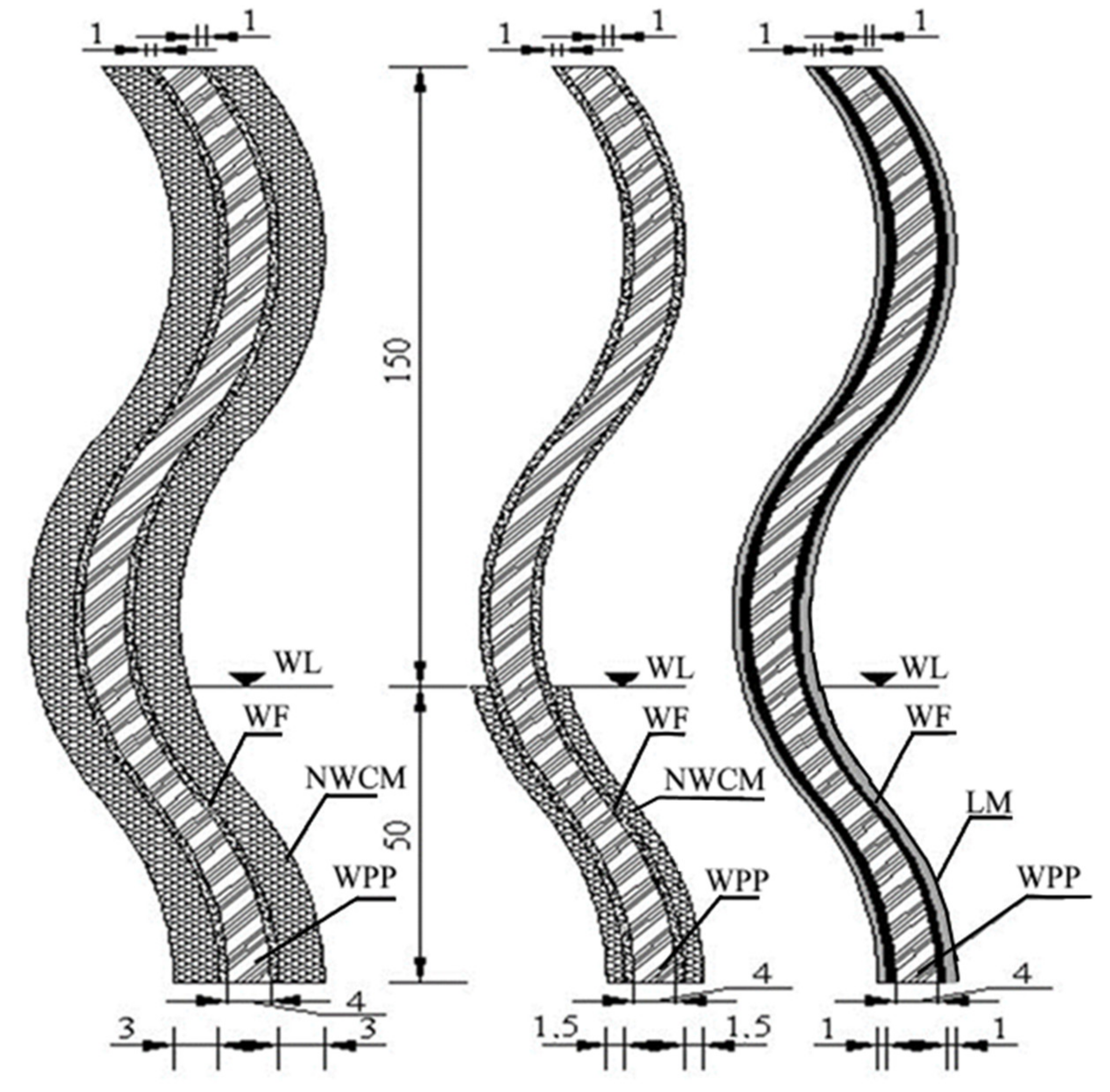
The packing material of the biofilter consisted of polyvinyl chloride (PVC) plates that were vertically arranged in parallel with each other. The different materials were attached to both sides of the wavy plates (Figure 2). The packing material was immersed in a liquid medium. The gaps between the plates were of 2–5 mm. The width of the gaps between the plates depended on the thickness and porosity of the attached material. The thicker and more porous attached material resulted in smaller gaps between the plates, because the humidified packing material swelled and reduced the width between the plates. The use of such structure of the packing material allow to reduce the pressure drop of the biofilter and promote the humidification of the packing material by capillary action.
Before the beginning of biofilter exploitation, the packing material was biologically activated using different kinds of microorganisms, i.e., the micromycetes Aspergillus versicolor, Gliocladium virens, Cladosporium herbarum, and Stachybotrys sp.; the yeasts Aureobasidium pullulans, Sporobolomyces roseus, and Exophiala sp.; and the bacteria Bacillus subtilis, Burgholderia cepacia, and Rhodococcus sp. After the activation, the packing material was covered with a thin (5–30 µm thick) biofilm layer. Throughout the experiments, the air temperature of 28 ± 2 °C was maintained in the biofilter for optimum growth of the microorganisms. The microorganisms were acclimated for 2 weeks. Additionally, this time was sufficient for uniform water distribution within the plates of the packing material. Later, after 2 weeks, the experiments were launched.

2.2. Pressure Drop Measurements

The pressure drop in the designed WL plate-type biofilter was studied using different compositions of materials (Figure 2), namely (I) WF, (II) NWCM and WF, and (III) LM and WF, which were attached to WPP. The pressure drop of the biofilter was determined by measuring pressure in the inlet and outlet ducts, and also across the packing material (between the plates). The pressure drop across the packing material was studied taking into account the number of the plates, as well as their length and height. The height of the packing material was 200 mm and the length was 900 mm. The thickness of the wavy plate depended on the composition of the packing material (Figure 2).
The pressure drop in the biofilter was measured using a Testo 512 digital differential pressure meter. The measurement was in the range of 0.1 to 200 Pa (with an accuracy of ±0.1 Pa). Air velocity (in the range of 0.05 to 10 m/s and with an accuracy of ±0.01 m/s), temperature (in the range of −20 to 180 °C and with an accuracy of ±1 °C), and humidity (in the range of 0 to 100%) were measured using a Testo 400 instrument. The instrument was used for determining air temperature across the plates of the packing material.
As the pressure drop strongly depends on the porosity of the material, open porosity (%) of used materials was determined using the water saturation and immersion technique. The determined open porosities of WF, NWCM, and LM were 52.9, 89.2, and 68.0%, respectively.
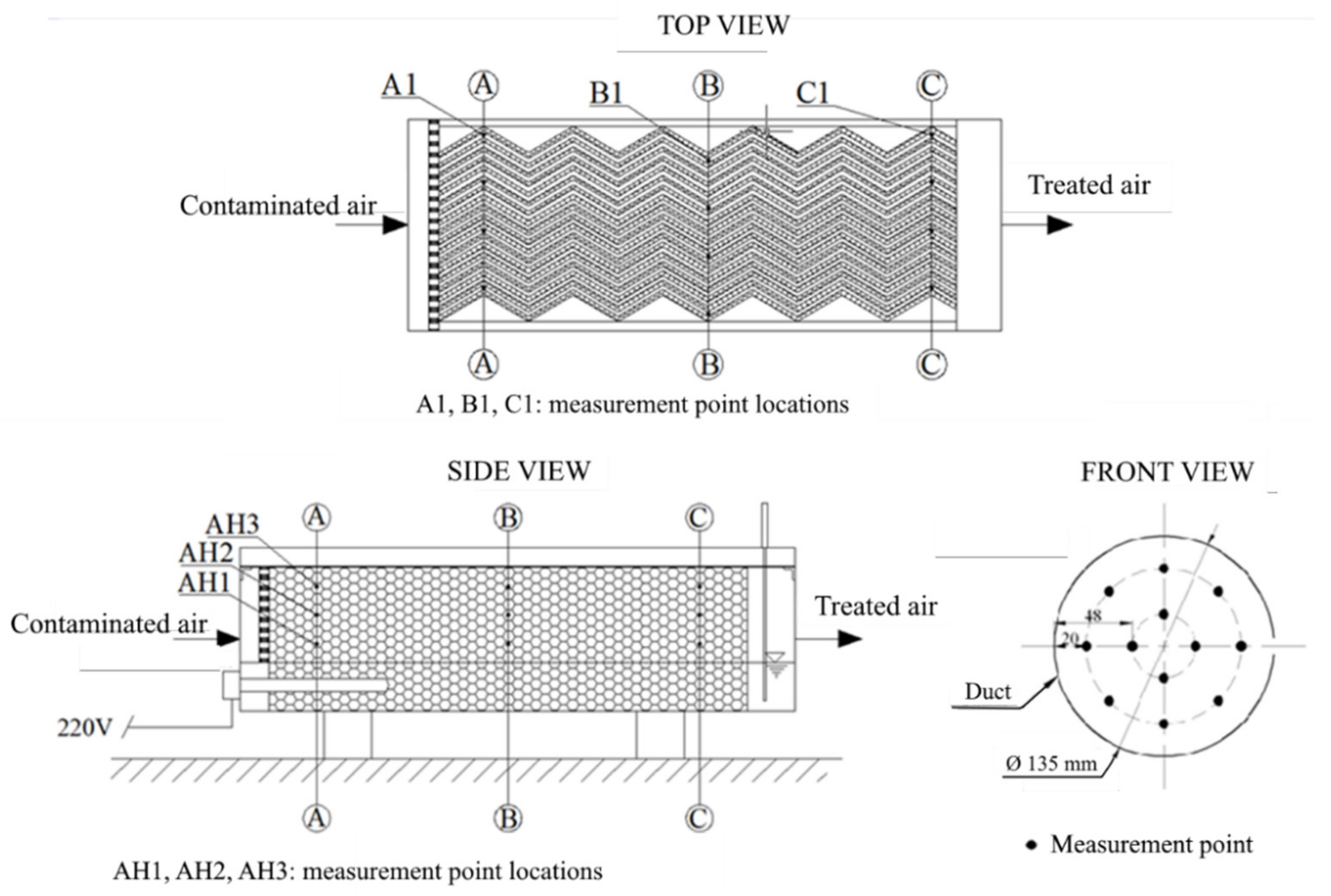
The points used for determining the pressure drop across the packing material of the biofilter are shown in Figure 3 (top and side views). The pressure was measured at a total of 36 points (12 points at each section). The pressure drop was also measured between the inlet and outlet ducts. The disposition of the points in the ducts is shown in Figure 3 (front view). As the cross-section pressure distribution in the duct was uneven, pressure was measured at the distance of 20 and 48 mm from the wall of the duct (Figure 3, front view). The pressure was measured at 12 points in each of the duct (24 points in total). The measuring results were recorded when the airflow was steady.
In this study, a theoretical model of airflow movement between the wavy plates of the packing material was also made.

2.3. Statistical Data Evaluation

All measurements were performed in triplicate. An analysis of variance (ANOVA) and a post hoc test were applied to differentiate between the means of experimental results. A significance level of 0.05 was used in statistical analysis.

3. Results and Discussion

3.1. Pressure Drops of Different Packing Materials

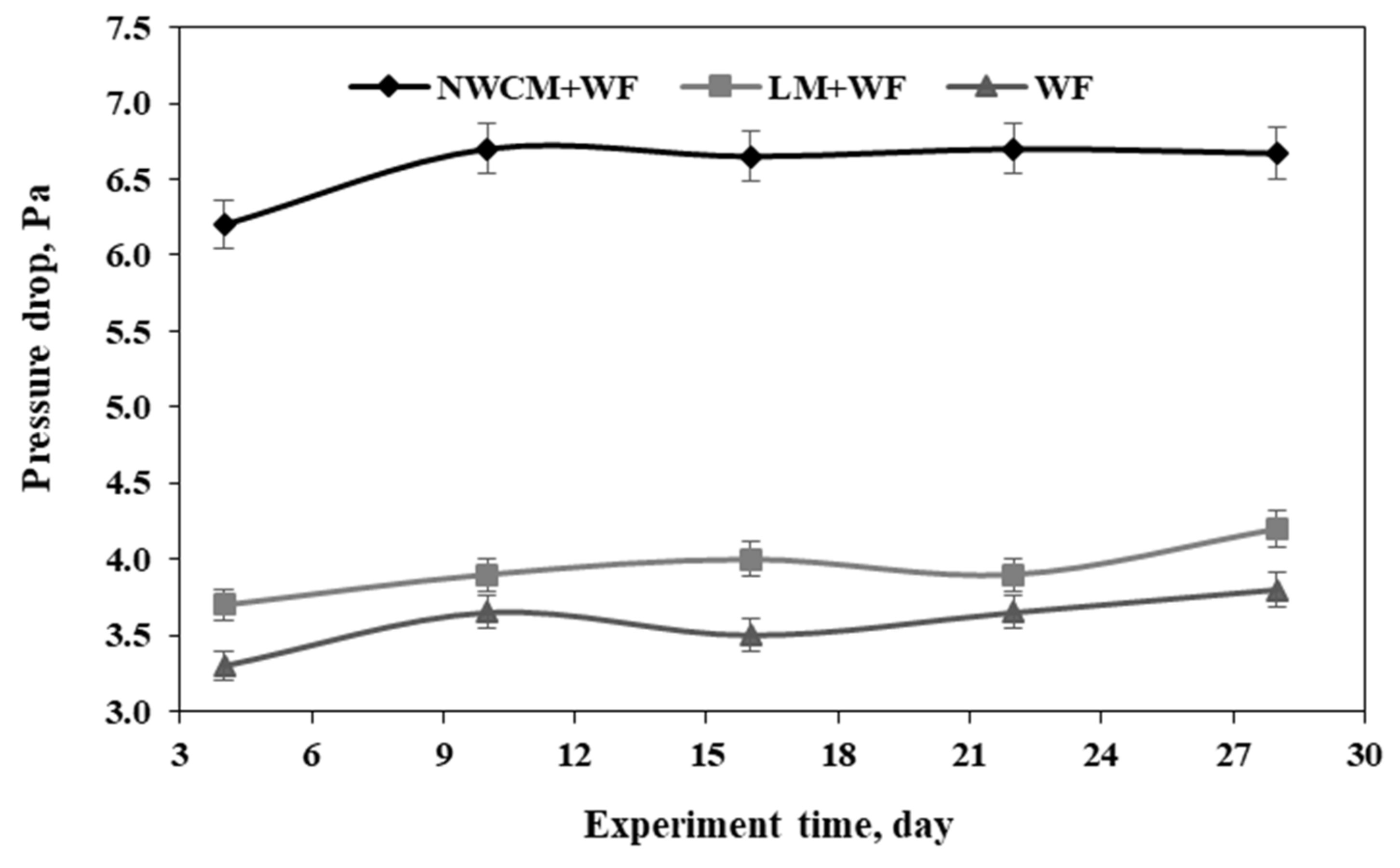
The pressure drop was measured in the biofilter (between the inlet and outlet ducts), applying different compositions of packing materials. The obtained results of the pressure drop in the biofilter with different packing materials are presented Figure 4.
The highest pressure drop in the biofilter was determined when the packing material with NWCM and WF was used and reached 6.7 Pa. This pressure drop was 1.5 times stronger compared to the pressure drop observed in the previous study [19], where a laboratory-scale biofilter with straight lamellar plates and the same composition of the packing material was applied. Due to the non-rectilinear flow of air, compared to the linear design packing material, a higher pressure drop was observed in the WL design biofilter. In the WL structure, air is forced to flow around the elevations of the packing material, which resulted in an increase in the air contact with the surface of the packing material and in a pressure drop. The lowest determined pressure drop was in the biofilter in which the packing material was composed of WPP and WF and reached on average 3.6 Pa. The pressure drop in the biofilter in which the packing material was made of WPP, LM, and WF on average was 3.9 Pa and was significantly higher compared to the biofilter in which the packing material was made of WPP and WF. The study revealed that the overall pressure drop in the biofilter with different packing materials was not high. In all cases, the lowest pressure drop in the biofilter was determined on the 4th day of the experiment, and on the 10th day, it increased by 8, 5, and 10% for packing material composed of NWCM + WF, LM + WF, and WF, respectively. The observed increase was significant for packing materials composed of NWCM + WF and WF. The pressure drop of packing materials composed of LM + WF and WF was the highest at 28th day of the experiment, and reached 4.2 and 3.8 Pa, respectively. In case of using packing material composed of NWCM + WF, differences between the means of pressure drops obtained at 10th, 16th, 22nd, and 28th days were not significant.
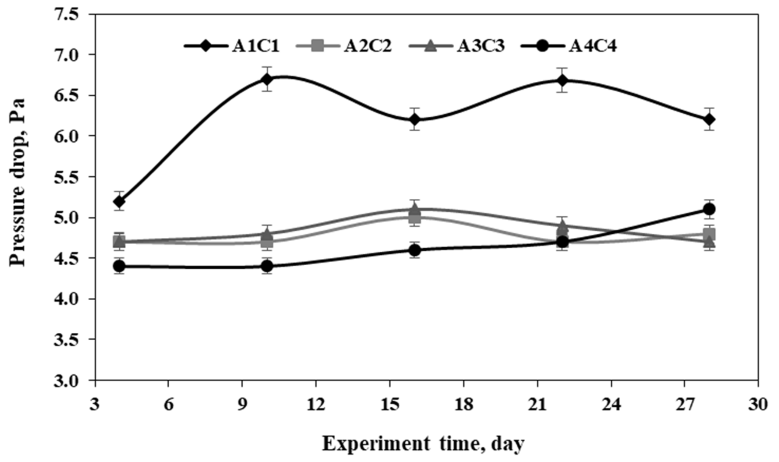
The pressure drop across the different used packing materials was determined between the points A1 and C1, A2 and C2, A3 and C3, and A4 and C4. Points A1–A4 and C1–C4 were located at a distance of 15 cm from the inlet and outlet ducts, respectively. During the first days of the experiments, when the packaging material was composed of WPP, NWCM, and WF, the pressure drop across the packing material in A1C1 lateral cross-section was approximately of 5.2 Pa and gradually increased to 6.2–6.7 Pa during the rest of the experiment. The increase of the pressure drop can be explained by the fact that NWCM expanded when absorbing humidity and therefore the space between the plates decreased, causing an increase in the pressure drop. When the humidity of the packing material became steady, only a slight variation in the pressure drop (6.2–6.7 Pa) was observed. In the other three lateral cross-sections of the packing material composed of WPP, NWCM, and WF, the pressure drop was almost steady and varied between 4.4 Pa and 5.1 Pa (Figure 5). The pressure drop mostly depended on the distances between the plates of the packing material. Within the first days, the space between the plates in cross-section A1C1 reached approximately 4–5 mm, and under humidified and enlarged packing material, the space decreased to 3 mm, which resulted in significantly higher pressure drop in this cross-section, compared to the other cross-sections where the space between the plates was 5–6 mm. Therefore, such distances had a significant role in obtaining a lower and more steady pressure drop during the experiment.
The airflow rate also has an influence on the pressure drop across the packing material. In general, when airflow is greater (and velocity is also higher), the pressure drop in the packing material gets higher [20]. In our study, the air velocity in the biofilter reached 0.08 m/s; therefore, obtained pressure drop across the packing material was not high. The difference in the pressure drop between the points of cross-section fluctuated from 0.2 to 1.8 Pa, depending on the humidity of the packing material.
The considerably lower pressure drop was achieved in the designed WL plate-type biofilter compared to the pressure drop in the biofilters studied by the other authors. This result can be explained by the fact that air stream in the studied biofilter flowed through parallel plates separated by millimeter gaps, while in some of the other studied biofilters, the air stream fully passes through the entire volume of the packing material, which results in a higher pressure drop [21,22].
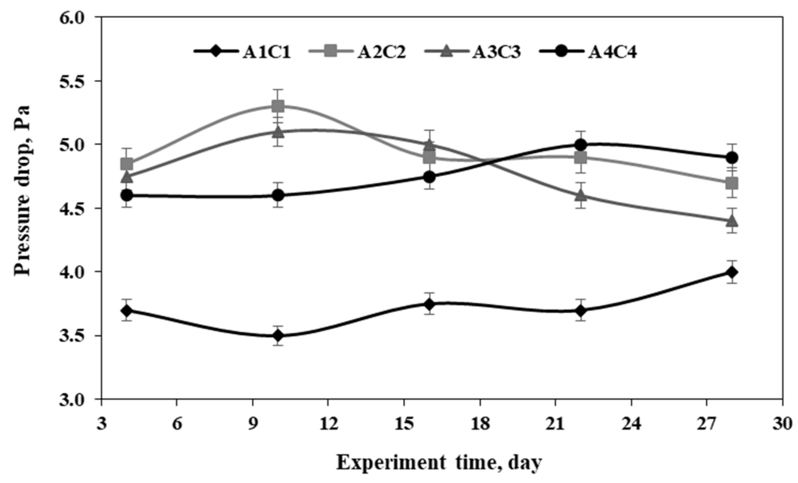
Figure 6 presents the pressure drop across the biofilter packing material made of WPP, LM, and WF. When using the packing material composed of WPP, LM, and WF in the biofilter, the lowest pressure drop was determined in cross-section A1C1, where the space between PVC plates were of 6 mm, and the pressure drop during the experiments varied from 3.5 to 4.0 Pa (Figure 6). The pressure drop in other cross-sections A2C2, A3C3, and A4C4 varied from 3.8 to 5.3 Pa and was significantly higher (by 2–3.3 Pa) compared to that in cross-section A1C1, which happened because of smaller spaces between the plates in these cross-sections, which differed from 4 to 5 mm. Unequal spaces were caused by differences in humidity and expansion of plates. Pressure drop differences between studied cross-sections A2C2, A3C3, and A4C4 were up to 0.9 Pa and could be caused by a varying degree of humidity in the plates of the packing material. Such differences could also be caused by slight variation in the airflow temperature.
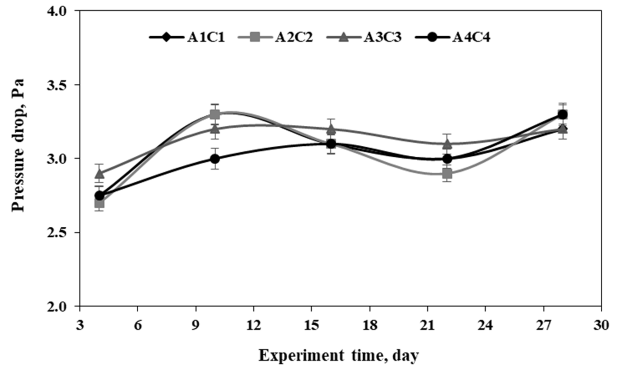
Figure 7 shows the pressure drop across the biofilter packing material made of the WPP and WF. When the packing material was composed of WPP and WF, the pressure drop in the biofilter was the lowest compared to that in the biofilter packed with other packing material compositions (Figure 7). The expansion of this packing material was little influenced, and therefore, the spaces between the plates remained very similar, i.e., 5–6 mm. The least expansion of this packing material composition could be explained by the lower WF open porosity (52.9%) compared to the other used materials. This resulted in the lower amount of water entering WF. In addition, it was also observed that the pressure drop across this packing material from the 4th to 28th day of the experiment was similar in all four studied cross-sections (with the exception of 10th day, when the pressure drop in cross-section A4C4 was significantly lower compared to that in other cross-sections) and reached, on average, 3.1 Pa. This composition of packaging material can be characterized by the lowest roughness of the surface compared to the other packing material compositions, which resulted in a pressure drop between plates of about 0.2 Pa.
In addition, in this study, the inlet air temperature (28 ± 2 °C) was close to the room temperature and was maintained steady throughout the experiment. Therefore, it can be stated that the air temperature did not have a considerable effect on the pressure drop in the biofilter with different packing materials.

3.2. Modeling of Airflow Movement

The structure of the designed biofilter is such that the air velocity between the plates is low (i.e., about 0.08 m/s). Thus, such air movement can be outlined by a small Reynolds number. Hence, Navier-Stokes equations for such movement can be expressed by rejecting convective components:
F x 1 ρ p x + v Δ u x = u x t
F y 1 ρ p y + v Δ u y = u y t
F z 1 ρ p z + v Δ u z = u z t
Supposing that the mass force vector is constant F = c o n s t , we differentiate Equations (1)–(3) with respect to x, y, and z, then calculate the sum of the equations.
When the divergence of velocity vector is d i v u = 0 (continuity equation), the harmonious function of pressure can be expressed:
Δ p 2 p x 2 + 2 p y 2 + 2 p z 2 = 0
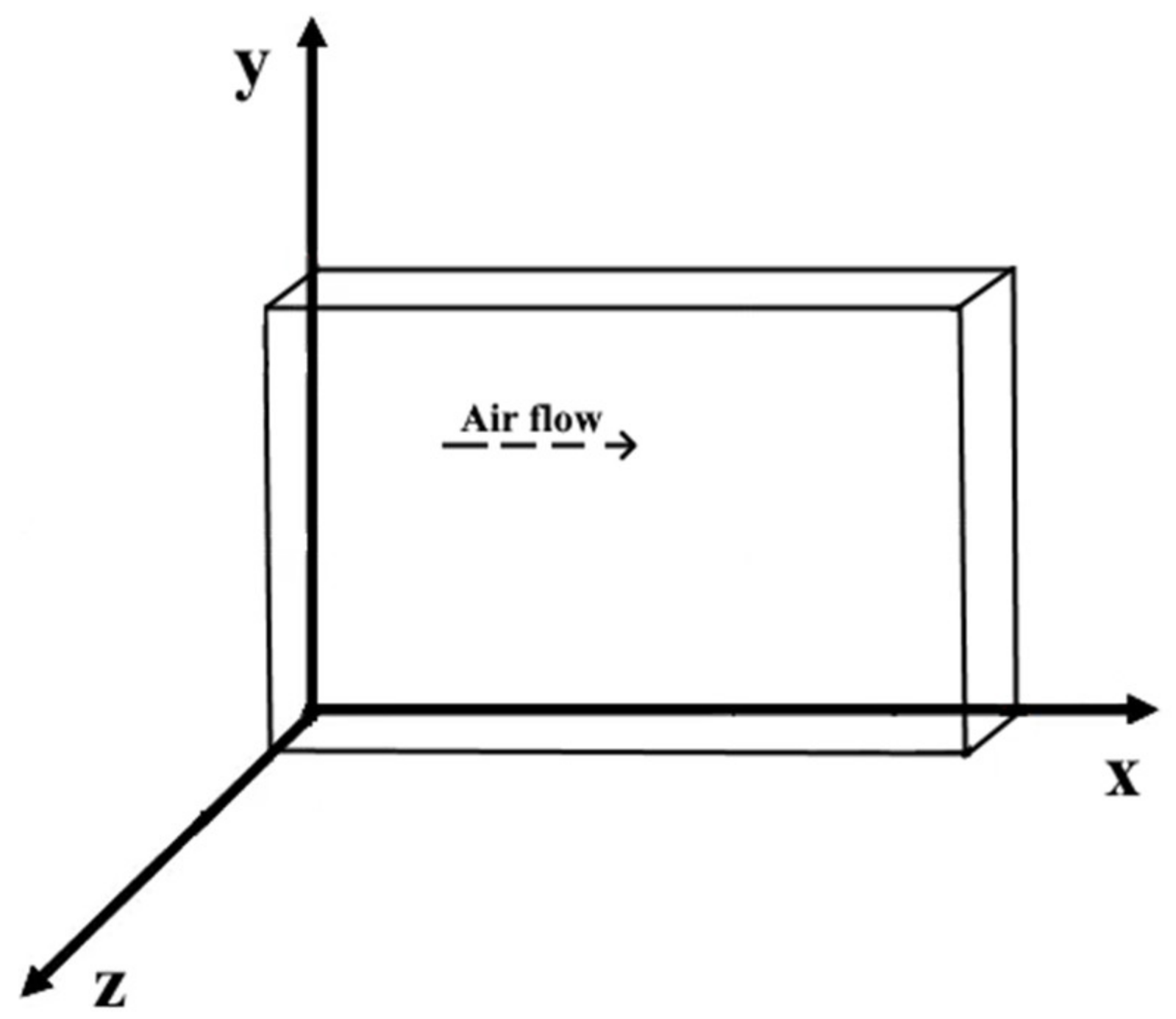
The length and height of the plates of the packing material are much greater than the spaces between them (Figure 8), and therefore, the kinematic characteristics of airflow can be assumed as those not depending on z coordinate, i.e., u z = 0 , and air movement will be considered as a plane.
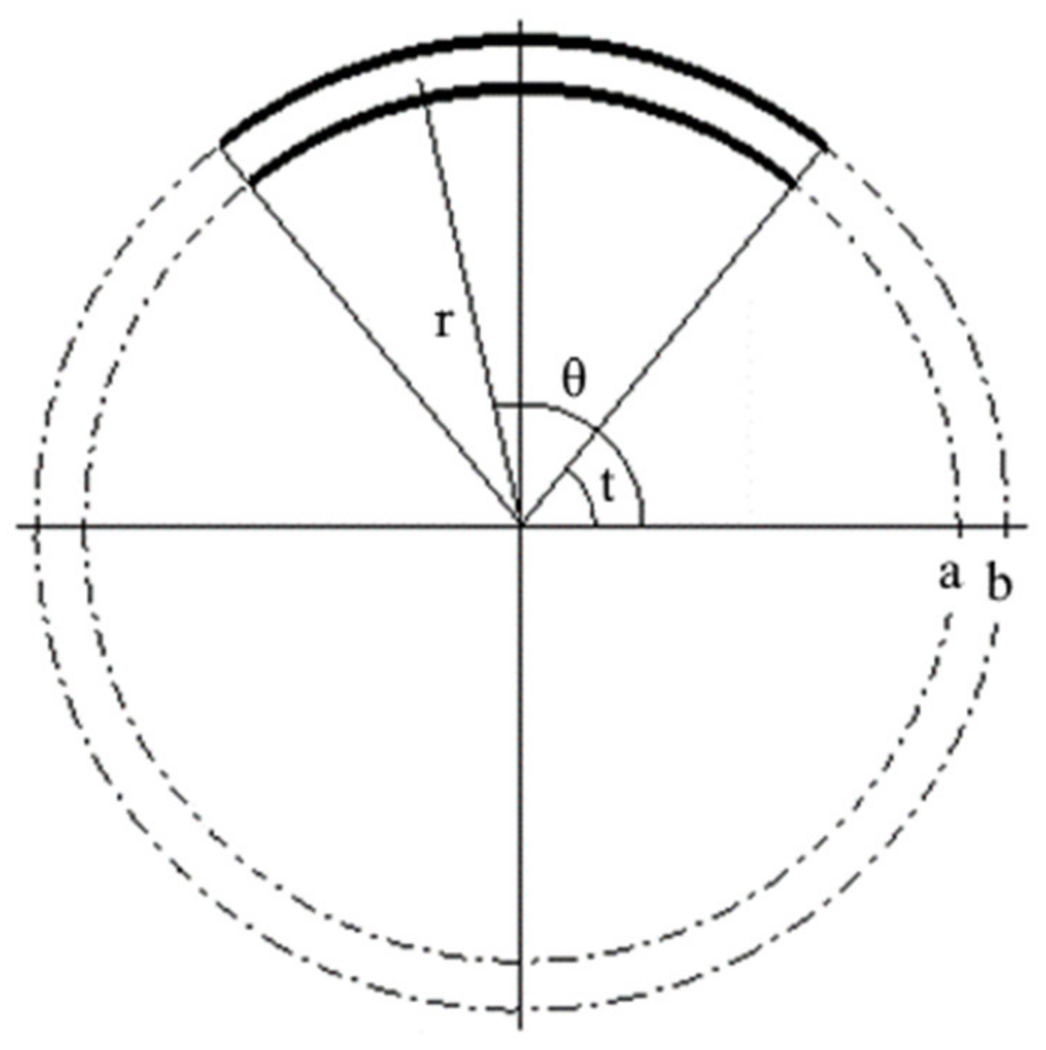
Thus, dealing with the problem of velocity and pressure distribution between the plates of the biofilter and maintaining the provisions of a general theory, the airflow is examined in the area between any concentric circles, of which the radii are a and b and the polar angle is θ (Figure 9).
It should be noted that the air movement between linear (not wavy) infinite (or large compared to the distance between them) plates strongly agreed with the results of the conducted experiments; moreover, this theory was justified when one of the above introduced plates use small curvature plates. In this case, the air movement between two close straight lines or slight curves is planar, which allows the assumption that pressure changes linearly ( p / x = c o n s t ) and does not depend on coordinate y ( p / y = 0 ).
In the case of the ring-shaped area (Figure 9), it can be assumed that the pressure remains the same in its perpendicular cross-section and varies only in the direction of polar angle θ, whereas the velocity depends on the other polar coordinate r. Thus, it is appropriate to consider the Navier-Stokes continuity equation in the polar coordinate system:
F r 1 ρ p r + v 2 u r r 2 + 1 r u r r + 1 r 2 2 u r θ 2 2 u θ θ u r r 2 = 0
u r r + 1 r u θ θ + u r r = 0
where velocity vector u = u r r , θ ; u θ r , θ .
Excluding the forces of mass (due to the low speed and density of moving air), we assume that u r 0 , u θ = u θ r , p = p θ . Thus, this system (Equations (5)–(7)) can be expressed in a single equation:
1 ρ p θ = v r 2 u θ r 2 + u θ r + 1 r 2 u θ θ 2 u θ r
where the left part depends only on θ, whereas the right part depends only on r. Therefore, ∂p/∂θ =c=const) and:
p = p θ = θ c 1 + c 2
Because the velocity near the walls is equal to 0 ( u θ a = u θ b = 0 ), the solution of Equation (1) satisfies these conditions:
u θ r = c 1 v ρ a 2 2 ln a 1 + b 2 1 2 ln b 4 b 2 a 2 r + a 2 b 2 ( ln b ln a ) 2 b 2 a 2 1 r + r 2 ln r 1 4
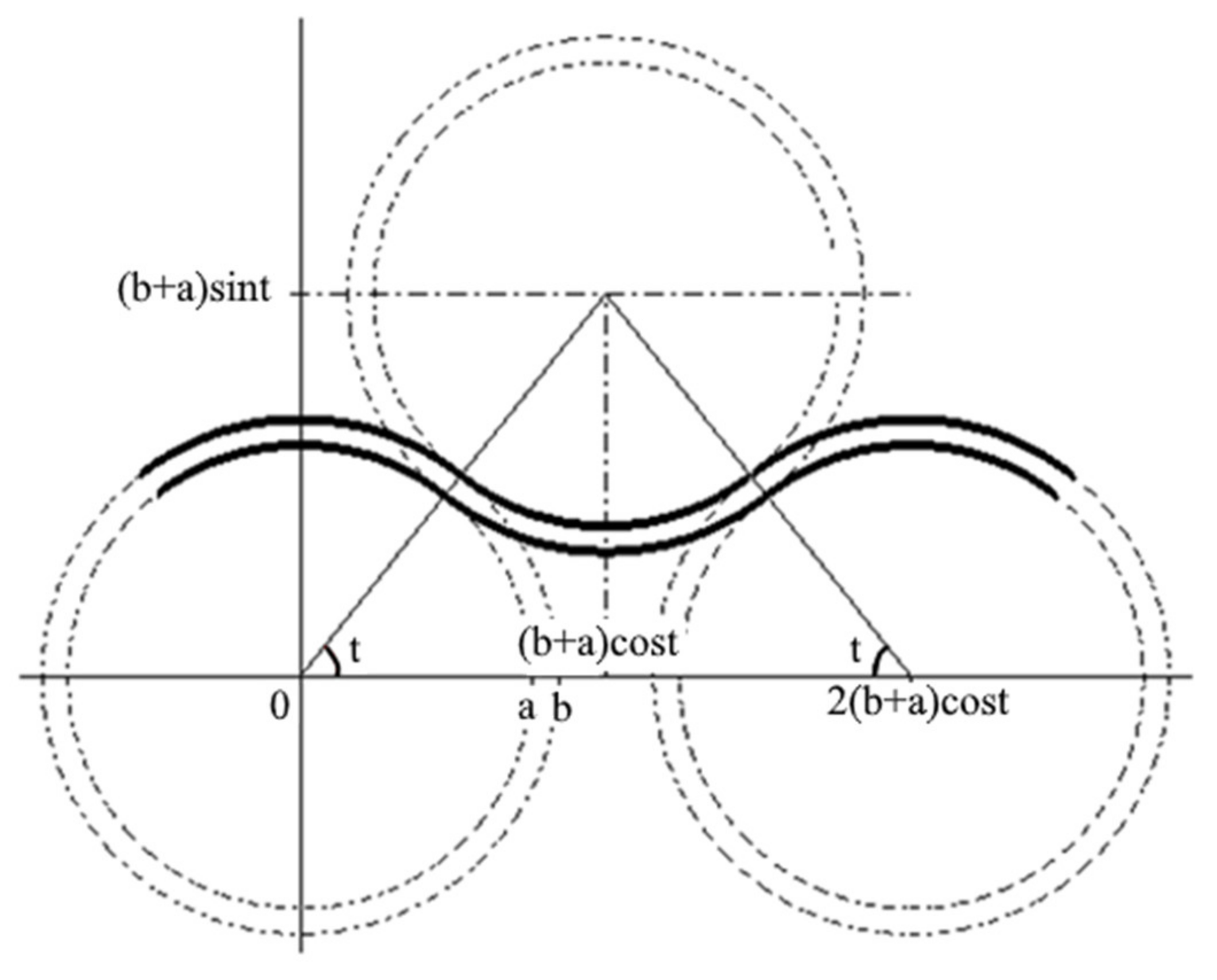
To describe the air flow movement along the whole wavy channel, we arrange the pole of the second polar system at the point a + b cos t ; a + b sin t and limit the second ring area by the circles of the same radii a and b (Figure 10). In this case, we can observe the same velocity distribution as in the first ring area. This process can be continued indefinitely.
With reference to data on the conducted experiments, the average values of p/θ were calculated. Based on the obtained expression (Equation (10)) and assuming that air velocity at all points is constant, u θ = 0.08 m/s, and the radius of the wave of the plate is a = 0.03 m, we found the values of distances between the plates h = b a , which varied between 1.5 and 3.0 mm, i.e., were lower than those measured between the plates of the packing material. The distances between the plates in real experiments were not kept as uniform, which may result in significant local pressure drops reaching few pascals. Uneven distances between the plates could be explained by the slight variation in the humidity of different plates of the packing material.

4. Conclusions

The pressure drop of three different compositions of packing materials of a laboratory scale WL plate-type biofilter was studied. The research results showed that the pressure drop in the biofilter depended on the composition of the packing material. The highest pressure drop was observed under the application of the biofilter with the packing material composed of NWCM and WF, i.e., 6.7 Pa, whereas the lowest one was observed under the application of packing material composed of WF and was 3.3 Pa. The use of the packing material composed of LM and WF in the biofilter allowed variations in the pressure drop between 3.7 Pa and 4.2 Pa. The obtained pressure drop differences between the different packing materials were statistically significant (p < 0.05). The pressure drop of the packing material composed of WF was the lowest compared with the other two compositions due to the fact that humidified WF expanded the least, and therefore, formed lower surface roughness compared to compositions made from NWCM and WF or LM and WF. For the pressure drop across the packing material, during the first days of the study, due to being incomplete, caused its humidification to be lower. When the packing material fully humidified, and therefore, expanded, the pressure drop increased and remained similar for the rest of the study. The theoretical model of the airflow movement between the wavy lamellar plates of the biofilter was introduced. A slight inconsistency between the theoretical assumptions and experimental results were obtained, which can be explained by the unevenness of the plates arranged in the structure of the biofilter.

Author Contributions

Conceptualization, P.B. and T.J.; methodology, P.B. and J.K.; validation, T.J. and J.K.; formal analysis, T.J.; investigation, T.J.; resources, P.B.; data curation, P.B.; writing—original draft preparation, T.J. and J.K.; writing—review and editing, P.B.; supervision, P.B. All authors have read and agreed to the published version of the manuscript.

Funding

This research received no external funding.

Institutional Review Board Statement

Not applicable.

Informed Consent Statement

Not applicable.

Data Availability Statement

The data supporting the findings of this study are available within the article.

Conflicts of Interest

The authors declare no conflict of interest.

References

  1. Rene, E.R.; Murthy, D.V.S.; Swaminathan, T. Effect of Flow Rate, Concentration and Transient—State Operations on the Performance of a Biofilter Treating Xylene Vapors. Water Air Soil Pollut. 2009, 211, 79–93. [Google Scholar] [CrossRef]
  2. Baltrėnas, P.; Januševičius, T.; Zagorskis, A.; Baltrėnaitė-Gedienė, E. Removal of ammonia by biofilters with straight and wavy lamellar plates. Int. J. Environ. Sci. Technol. 2020, 2020, 1–10. [Google Scholar] [CrossRef]
  3. Jeong, D.; Oh, J.; Yum, I.; Lee, Y. Removal of VOCs from their aqueous solution by pervaporation with PDMS-zeolite composite membrane. Desalin. Water Treat. 2010, 17, 242–247. [Google Scholar] [CrossRef]
  4. Omri, I.; Aouidi, F.; Bouallagui, H.; Godon, J.-J.; Hamdi, M. Performance study of biofilter developed to treat H2S from wastewater odour. Saudi J. Biol. Sci. 2013, 20, 169–176. [Google Scholar] [CrossRef] [PubMed] [Green Version]
  5. Santos, S.; Jones, K.; Abdul, R.; Boswell, J.; Paca, J. Treatment of wet process hardboard plant VOC emissions by a pilot scale biological system. Biochem. Eng. J. 2007, 37, 261–270. [Google Scholar] [CrossRef]
  6. Zigmontienė, A.; Žarnauskas, L. Investigation and analysis of air-cleaning biofilter hybrid biocharge quantitative and qualitative parameters. J. Environ. Eng. Landsc. Manag. 2011, 19, 81–88. [Google Scholar] [CrossRef]
  7. Sakuma, T.; Jinsiriwanit, S.; Hattori, T.; Deshusses, M.A. Removal of ammonia from contaminated air in a biotrickling filter—Denitrifying bioreactor combination system. Water Res. 2008, 42, 4507–4513. [Google Scholar] [CrossRef]
  8. Baltrėnas, P.; Zagorskis, A. Investigation into the Air Treatment Efficiency of Biofilters of Different Structures. J. Environ. Eng. Landsc. Manag. 2010, 18, 23–31. [Google Scholar] [CrossRef]
  9. Gaudin, F.; Andrès, Y.; Le Cloirec, P. Packing material formulation for odorous emission biofiltration. Chemosphere 2008, 70, 958–966. [Google Scholar] [CrossRef]
  10. Gallastegui, G.; Ramirez, A.Á.; Elías, A.; Jones, J.; Heitz, M. Performance and macrokinetic analysis of biofiltration of toluene and p-xylene mixtures in a conventional biofilter packed with inert material. Bioresour. Technol. 2011, 102, 7657–7665. [Google Scholar] [CrossRef]
  11. Lee, S.-H.; Li, C.; Heber, A.J.; Ni, J.; Huang, H. Biofiltration of a mixture of ethylene, ammonia, n-butanol, and acetone gases. Bioresour. Technol. 2013, 127, 366–377. [Google Scholar] [CrossRef]
  12. Rahul; Mathur, A.K.; Balomajumder, C. Biological treatment and modeling aspect of BTEX abatement process in a biofilter. Bioresour. Technol. 2013, 142, 9–17. [Google Scholar] [CrossRef]
  13. Woudberg, S.; Van Jaarsveld, J.; Dumont, E. Predicting the pressure drop of a biofilter and the specific surface area of the packing material. Powder Technol. 2019, 342, 233–245. [Google Scholar] [CrossRef]
  14. Shareefdeen, Z.; Herner, B.; Webb, D.; Polenek, S.; Wilson, S. Removing volatile organic compound (VOC) emissions from a printed circuit board manufacturing facility using pilot- and commercial-scale biofilters. Environ. Prog. 2002, 21, 196–201. [Google Scholar] [CrossRef]
  15. Ryu, H.W.; Cho, K.-S.; Chung, D.J. Relationships between biomass, pressure drop, and performance in a polyurethane biofilter. Bioresour. Technol. 2010, 101, 1745–1751. [Google Scholar] [CrossRef]
  16. Dorado, A.D.; Lafuente, J.; Gabriel, D.; Gamisans, X. The role of water in the performance of biofilters: Parameterization of pressure drop and sorption capacities for common packing materials. J. Hazard. Mater. 2010, 180, 693–702. [Google Scholar] [CrossRef]
  17. Morgan-Sagastume, F.; Sleep, B.E.; Allen, D.G. Effects of Biomass Growth on Gas Pressure Drop in Biofilters. J. Environ. Eng. 2001, 127, 388–396. [Google Scholar] [CrossRef]
  18. Andreasen, R.R.; Nicolai, R.E.; Poulsen, T.G. Pressure drop in biofilters as related to dust and biomass accumulation. J. Chem. Technol. Biotechnol. 2012, 87, 806–816. [Google Scholar] [CrossRef]
  19. Baltrėnas, P.; Kleiza, J.; Idzelis, R.L. Investigation into The Aerodynamic Processes Of Air Treatment Using A Plate-Type Biofilter. Environ. Technol. 2015, 37, 1–13. [Google Scholar] [CrossRef]
  20. Baskaran, D.; Rajamanickam, R.; Vaidyalingam, B. Effect of concentration and gas flow rate on the removal of gas-phase trichloroethylene in a novel packed biofilter. Bioresour. Technol. Rep. 2020, 9, 100387. [Google Scholar] [CrossRef]
  21. Kennes, C.; Thalasso, F. Review: Waste gas biotreatment technology. J. Chem. Technol. Biotechnol. 1998, 72, 303–319. [Google Scholar] [CrossRef]
  22. Kumar, M.; Giri, B.S.; Kim, K.-H.; Singh, R.P.; Rene, E.R.; López, M.E.; Rai, B.N.; Singh, H.; Prasad, D.; Singh, R.S. Performance of a biofilter with compost and activated carbon based packing material for gas-phase toluene removal under extremely high loading rates. Bioresour. Technol. 2019, 285, 121317. [Google Scholar] [CrossRef] [PubMed]
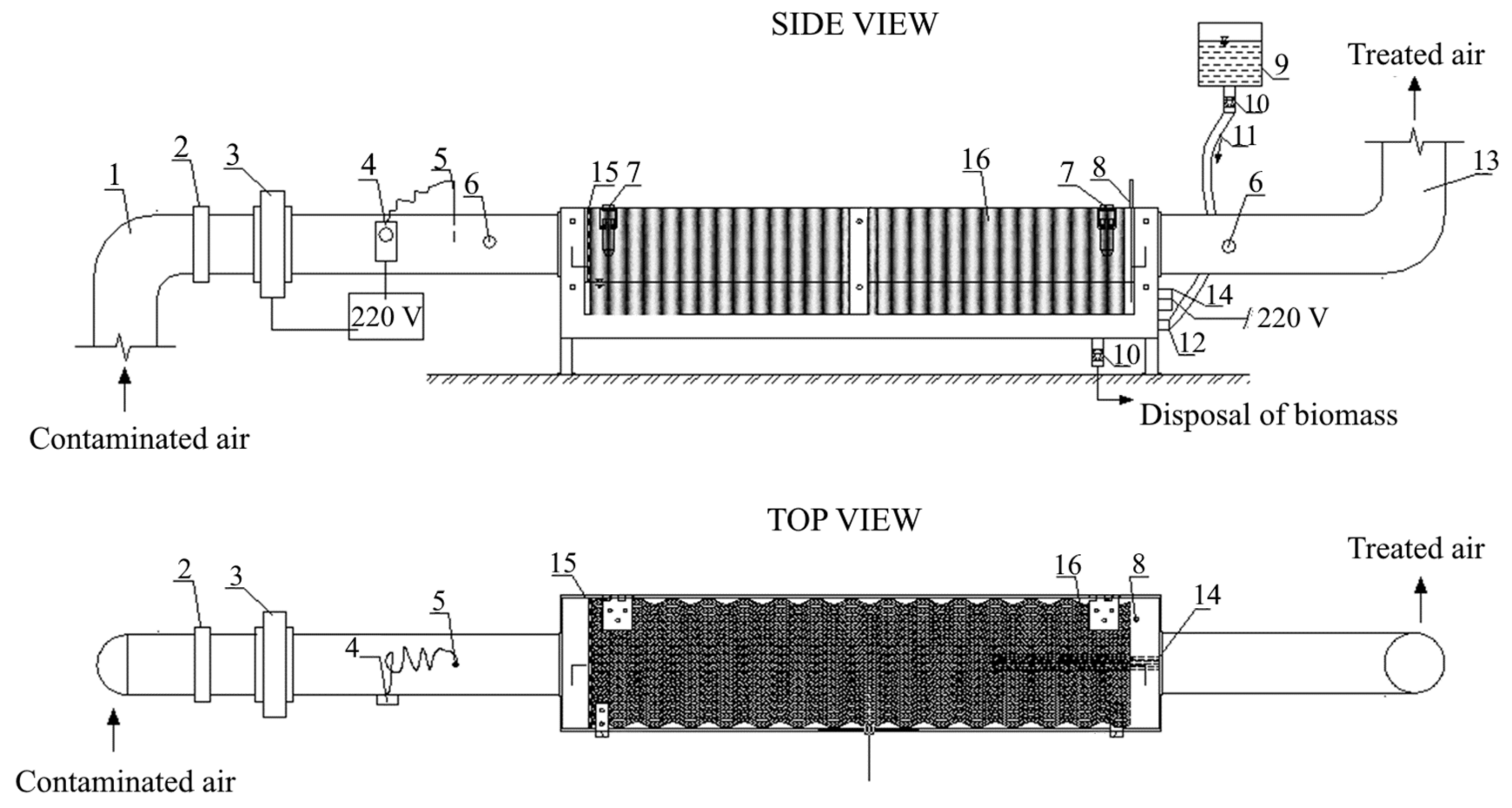
Figure 1. Scheme of the wavy lamellar plate-type biofilter. 1—the inlet duct, 2—a valve, 3—ventilator, 4—a thermostat, 5—a heater with a thermostat, 6—a sampling sites, 7—a fastening element, 8—a temperature sensor, 9—a water tank, 10—a drain valve, 11—a water refill hose, 12—a water inlet valve, 13—the outlet duct, 14—a heating element, 15—the perforated plate, 16—the packing material.
Processes 09 00625 g001
Figure 2. Compositions of the plates of the packing material. LM: Linen material, NWCM: Non-woven caulking material, WF: Wood fiber, WL: Water level, WPP: Wavy polymer plate.
Processes 09 00625 g002
Figure 3. The pressure measurement points: across the packing material (top and side views) and in the cross section of the inlet and outlet ducts (front view).
Processes 09 00625 g003
Figure 4. The pressure drop (Pa) in the biofilter with different packing materials. NWCM + WF: non-woven caulking material and wood fiber, LM + WF: linen material and wood fiber, WF: wood fiber.
Processes 09 00625 g004
Figure 5. The pressure drop (Pa) across the biofilter packing material (between the points A1 and C1, A2 and C2, A3 and C3, and A4 and C4) composed of WPP, NWCM, and WF.
Processes 09 00625 g005
Figure 6. The pressure drop (Pa) across the biofilter packing material (between the points A1 and C1, A2 and C2, A3 and C3, and A4 and C4) composed of WPP, LM, and WF.
Processes 09 00625 g006
Figure 7. The pressure drop (Pa) across the biofilter packing material (between the points A1 and C1, A2 and C2, A3 and C3, and A4 and C4) composed of WPP and WF.
Processes 09 00625 g007
Figure 8. Control volume of the airflow movement between the plates.
Processes 09 00625 g008
Figure 9. The circular area: t < θ < πt; a < r < b.
Processes 09 00625 g009
Figure 10. Scheme for joining areas.
Processes 09 00625 g010
Publisher’s Note: MDPI stays neutral with regard to jurisdictional claims in published maps and institutional affiliations.