1. Introduction
A growing share of heavy crude in the total volume of extractive raw materials of low-gas oil and light-fractions content, the necessity for crude upgrading to a minimum 95%, and growth of interest in the use of conventional heavy organic stock are key factors indicating the importance of R&D in searching for updated methods of refining heavy and residual hydrocarbon feedstock with high distillate yield for subsequent output of essential oil products [
1,
2]. Increased crude upgrading and, subsequently, yield of light oil products and petrochemical feed can be achieved by wide involvement of heavy residual fractions in refining, including naphtha residue, vacuum residue, and gas/oil fractions [
3,
4]. Physicochemical characteristics of heavy oil stock make its production, transportation, and subsequent refining rather difficult. These processes should be based on the breakage of C-C, C-S, C-N bonds and hydrogenation of resulting radical fragments, ensuring destruction of heavy organic stock leading to gasoline, average distillate, and gas oil fractioning with higher hydrogen/carbon ratio (H/C).
It is a challenge to develop catalysts for upgrading heavy oil stock, being a complex disperse system that is readily destabilized under reactions due to the formation of thermally unstable high-molecular destruction fragments of hetero-organic matters, tars, and asphaltenes [
5,
6,
7,
8,
9,
10].
Practically irreversible deactivation of conventional heterogeneous catalysts by metal-containing and heteroatomic compounds present in the feedstock requires the development and application of brand-new catalytic systems. They include nanosized or ultradispersed fractions stabilized in an organic medium and formed from catalyst precursors in hydrocarbon medium.
Heavy oil stock is the focus of the latest key theoretical and practical developments in the field of petroleum dispersal systems, establishment of technological principles of the refining, dehydration, and upgrading of distillates and naphtha residues. In particular, innovative approaches related to catalytic cracking, hydrogenation processes (hydrotreating, hydrocracking, hydrodearomatization, etc.), and the production of carbon black, petroleum coke, and bitumen have been implemented [
11,
12,
13].
Currently, the tendency toward heavier extractive oil is growing stronger across the world. In some countries, it is associated with both the development of hard-to-recover heavy oils, including bituminous, and with “aging” or maturity of fields, thus causing increased total sulfur content and density of the oil to be transported.
The strategy of leading Western refiners of heavy residual oil stock is mainly based on hydrogenation technologies. Primarily, they are: LC-Fining (Chevron Lummus Global) [
14], H-Oil (Axens), EST (Eni) [
15], HRS development—Institute of Petrochemical Synthesis RAS (IPChS RAS), HyvahlTM-process (IFP) [
16], HYCON (Shell), RDS/VRDS (Chevron Lummus Global), VCC (KBR), Uniflex (UOP), and others [
14,
15,
16,
17,
18,
19]. Processing of heavy residues by hydro-upgrading infers substantial costs associated with the need to meet stringent requirements set up for a process (high temperatures, pressure, presence of hydrogen), the use of catalytic systems resistant to carburizing and poisoning, extra preparation processes for stocks, and high-cost specialized equipment. Nevertheless, potential heavy stock refining into highly marketable oil products promotes the development of promising processes for upgrading of naphtha residues.
The hydroprocesses with moving-bed catalyst play a key role in the development of deep processing of heavy oils and residual stock. In this review, all the main modern technologies of hydrogenation processing were considered. These processes make it possible to obtain target distillate fractions from heavy viscous raw oils and residual feedstock.
2. Heavy Oils and Residual Stock
Heavy oils and residual stock are a complex multicomponent system distinguished by a high content of arenes, including polycyclic aromatic compounds, high-molecular alkane-naphtha-arene hydrocarbons, tars, asphaltenes, as well as hetero-atomic compounds and metals, with higher values of viscosity, density, and coking behavior being their characteristic features. High-molecular compounds are mainly composed of tar-asphaltene substances. Depending on the type of heavy oil fields, they can be classified according to the content of any hydrocarbon groups. For instance, Venezuela tars are known as naphtha tars, and Canadian tar sands can be referred to as aromatic base oils. Asphaltene molecules tend toward the development of aggregation and are able to form piles of interconnected, nearly flat molecules. In thermal oil treatment, these aggregates serve as coking behavior nuclei and cause a great amount of carbon depositions on every available surface.
Heteroatomic compounds (metals and nonmetals) contained in highly viscous oils and residual fractions affect crude-refining processes, as they contribute to increased equipment corrosion, catalyst poisoning, and substantial growth of harmful atmospheric emissions. [
20]. The presence of sulfur, oxygen, and mainly nitrogen atoms in organic compounds, especially in asphaltenes, causes great coordination of vanadium, nickel, and other metals with the above molecules, thus leading to certain problems while recovering metals in refining [
21,
22,
23]. Most metal impurities in oil distillates are in concentrations of about μg/kg, rarely mg/kg. They are present either as disperse particles (such as scale on pipe fittings), which can be removed after mechanical stock filtration, or as aryles (in general, porphyrinic), and stock dissolved compounds represented mostly by arsenic contained in some crudes, as mercury—from some condensates, and as silicon sourced by anti-foaming agents applied in visbreaking and coking. Residual type of stocks (naphtha residues, vacuum residues, and their blends) can contain metals as much as 500 mg/kg and more [
24,
25,
26].
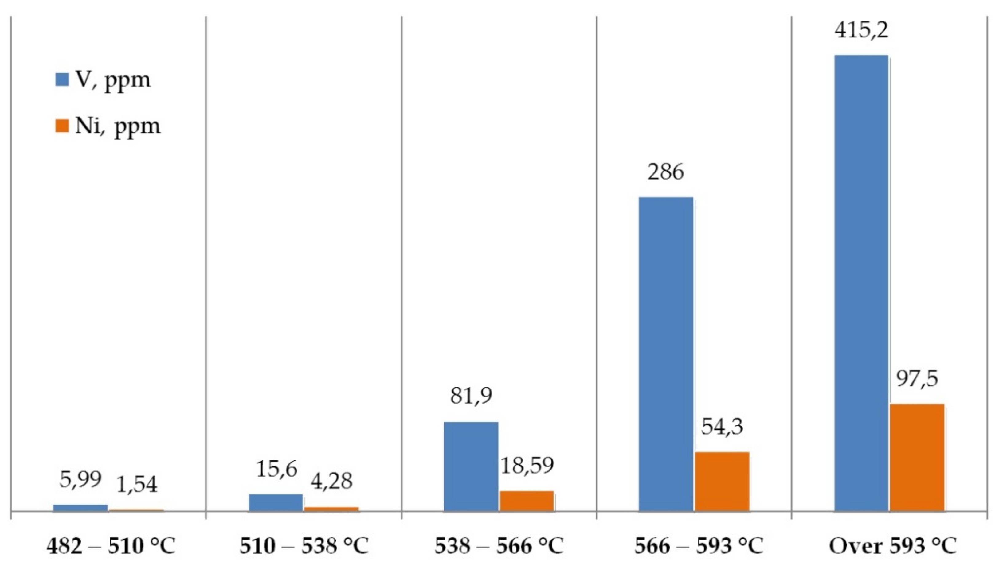
Figure 1 shows the Ni and V fractional distribution of heavy North American crude [
27].
The development of advanced methods of fractional distribution and identification for heavy oil analysis allowed the determination of the structure and composition of heavy oils and naphtha residues, and the examination of different groups of compounds based on their molecular mass and solubility in polar, aromatic, and nonpolar solvents. For example, bitumen can be classified as follows: saturated hydrocarbons soluble in n-heptane; aromatic hydrocarbons soluble in a toluene or methanol-toluene blend; polar resins soluble in trichlorethylene; or asphaltenes nonsoluble in n-heptane. Quantitative characteristics of Canadian bitumen for the groups listed are the following: 5–15 mass % of saturated hydrocarbons with average molecular mass (Mr) 600 and H/C = 2; 30–45 mass % of aromatic hydrocarbons (Mr = 800) and H/C = 1.5; 30–45 mass % of resins (Mr = 1100) and H/C = 1.4–1.5; and 5–20 mass % of asphaltenes with Mr = 800–3500 and H/C = 1.15.
At present, heavy oil, including bitumen, is looked upon as a colloidal system, being a dispersion of aggregates sized 12–15 nm that are collected from asphaltene micelles sized 3–4 nm stabilized with resin polar components. High-volume recovery or processing of continuous-phase components results in a loss of crude colloidal stability, i.e., enlargement of continuous phase particles—asphaltene aggregates, and that, undoubtedly, should be taken into consideration while processing heavy hydrocarbon stock [
28,
29,
30,
31,
32,
33,
34]. In blending of highly viscous resinous oils with lighter oils or petroleum cuts, compatibility problems occur, which, during transportation and storage, lead to separation of hydrocarbon stock and asphaltene-resin deposition or increased viscosity of the system due to asphaltene swelling [
35].
Distinctive features of heavy oil stock composition and structure result in high cost of production, practically impossible transportation through existing pipelines, and uneconomic refining under the classical conventional approach. Production, transportation, and refining of heavy oils pose specific problems to be solved by technologists and engineers as opposed to similar processes for light crudes [
36].
3. The Processing of Heavy Residual Stock
The most widely spread upgrading process of oil stock, including high-viscosity oils and black oils, is the process of delayed coking (DC). This process makes it possible to yield additional quantity of distillate fractions (end product: petroleum coke) and increase upgrading on the basis of reasonable capital and operating costs. The periods of reduced oil stock prices are most favorable for high popularity of the process. Though there are some problems with marketing of high-sulfur, low-grade coke, new delayed coking plants are being put into operation globally. Recently Russia has witnessed a growing interest in coking. DC plants have been commissioned at Ltd. LUKOIL- Permnefteorgsyntez, OJSC TANECO, and JSC Antipinsky NPZ. Annual total power of Russian DC plants equaled 13 million metric tons in 2019. It also caused about a 16% reduction of black oil share in the 2019 product basket, and about an 83.1% increase in crude upgrading in Russia.
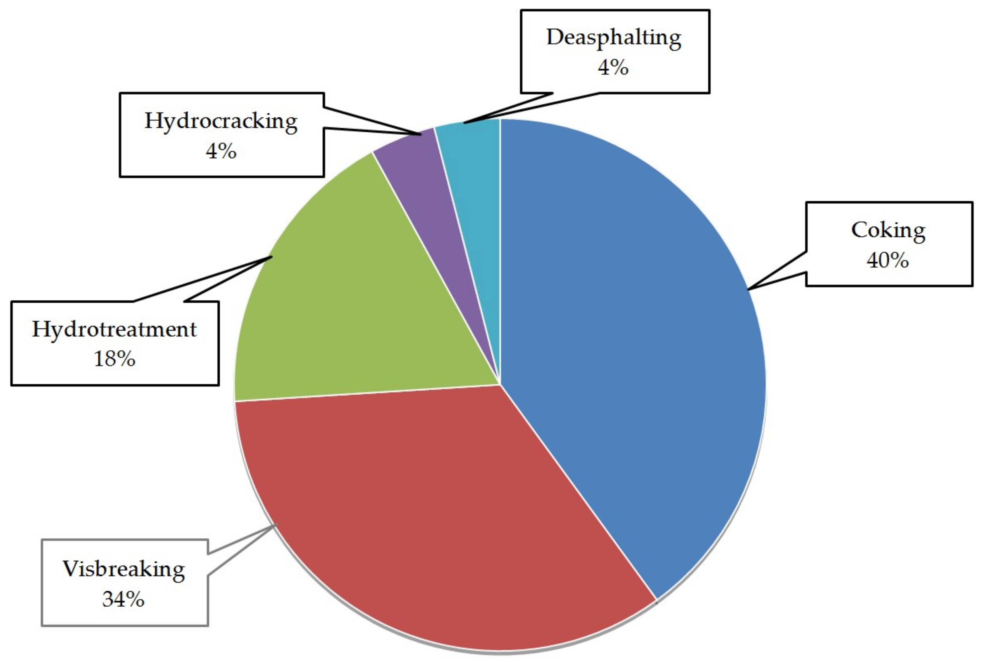
Alternatives to the carbon-release processes are those related to the hydrogen saturation of products—hydrogenation processes. As of today, these technologies are most popular for processing of heavy residual stock (HRS), allowing, as opposed to DC, the yield of products of better quality immediately.
Figure 2 shows the shares of technologies based on conventional processes in the structure of global HRS upgrading. A considerable contribution of visbreaking and coking processes can be credited to their relatively low capital costs [
35], about 4% of which fall under hydrocracking processes.
Using their functions, hydrogenation processes can be classified into hydrofining and hydrocracking of oil stock. Hydrofining is used to improve one or several characteristics of initial stock, and depending on more targeting functions, can be divided into hydrodemetallization, hydrodesulfurization, and hydrodenitration. Using this group of processes, one can achieve quality improvement owing to a reduced content of sulfur, nitrogen, and metals; and by catalytic cracking, hydrocracking, and/or coking, it is also possible to prepare heavy oil stock (HOS) for further upgrading. In general, in hydrofining processes, stock conversion does not exceed 10%, while in hydrocracking processes carried out under more stringent conditions (pressure—max. 30 MPa and temperature—max. 450 °C), it exceeds 25%. In hydrocracking, a rather severe destruction of HOS components occurs, with breaking of large original molecules into smaller ones. In contrast to thermal processes, HOS upgrading enables considerable improvement of quality and high yield (85% and higher) of resulting liquids. However, HOS upgrading processes are demanding regarding hydrogen and high capital and operating expenses. The urgent application problems of HOS hydro-upgrading are also higher carbon production and an allowable, relatively low metal content in HOS. These problems can cause a need for frequent regeneration and reactivation of catalysts, as well as their reduced life. Therefore, their application is not always cost-effective.
3.1. Catalytic Fixed-Bed Hydrocracking
One of the first commercially applied hydrogenation processes for upgrading of residual and heavy oil stock, along with hydrofining, was the technology of catalytic fixed-bed hydrocracking. HOS hydro-upgrading in catalytic fixed-bed reactors is currently the most widely spread commercial option of this process implementation. In upgrading of heavy oil and residual stock characterized by high coking behavior and considerable metal content, it is frequently decided to use the so-called protective reactors or protective catalyst beds. Such an approach enables the minimization of poisoning of the lower catalyst beds due to coke and metal accumulations on their surfaces, as well as the exclusion of a drastic increase in reactor pressure differential. Protective beds, in general, contain catalysts w/pores of large diameter, low activity, and high volume capacity with respect to solid deposition. The number of catalyst beds used is conditioned by the process function and required composition of products, but to a great extent it depends on the stock quality. According to the published data [
37], oil stock containing about 100 ppm of metals can be upgraded in catalytic fixed-bed reactors. However, provided highly active catalysts w/narrow pores are used, it is reasonable to upgrade stock in which metal concentration is a maximum of 25 ppm. For a stock containing 25–50 ppm of metals, a two-bed catalytic system is used, with the first bed having increased resistance to metal deposition. If metal concentration is in the range of 50–100 ppm, then a three-bed catalytic system is used—a front protective bed is formed with a hydrodemetallization catalyst remarkable for its high specific quantity of metal [
38].
Major problems arising from the use of catalytic fixed-bed reactors for HOS upgrading are associated with a quick activity reduction of first-in-downstream beds of the catalyst due to coke and metal accumulation, as well as adsorption of some other undesired compounds on its surface. Such problems can be partially solved by the development of highly active and solid-resistant catalysts, optimization of reactor height adjusted loading of several catalyst beds or inert particles different in size and grain shape, aperturate structure and activity, and the use of special apparatus for effective gas-liquid mixing and uniform reactor cross-sectional flux distribution. Engineering developments making it possible to solve the problem of continuous operation of the units are mainly focused on the use of catalytic moving-bed protective reactors ensuring continuous on-stream catalyst replacement [
37]. Catalytic fixed-bed hydro-upgrading of naphtha residues is characterized by low cost-efficiency indices, required frequent catalyst replacement, and severe on-stream technological conditions.
3.2. Moving-Bed Catalytic Processes
As it was necessary to lengthen catalyst life and optimize technological conditions for the hydro-upgrading process of heavy and residual stocks, some technologies using catalytic moving-bed reactors have been developed. The most popular are: RDS/VRDS/OCR (Onstream Catalyst Replacement) by Chevron Lummus Global (CLG), the HYCON process by Shell, RCD Unionfining (UOP LLC), and others [
38], designed to cut sulfur, nitrogen, asphaltenes, and metal compounds, and to reduce coking behavior of a residual stock. The purpose of the technologies is to yield high-grade fuel oil or perform further upgrading by hydrocracking, coking, and catalytic cracking.
Positioning the OCR reactor before the hydrodesulfurization reactor with a fixed-bed catalyst opens the way to increasing process capacity of stock and/or allows upgrading of heavy oil stock of high metal content (over 400 ppm), while maintaining a high grade of products and the efficiency of the process. The OCR presence in the hydroprocess flow diagram makes it possible to extend the lifetime of the hydrodesulfurization catalyst and solve the problem of bed differential pressure rise. In this case, the new catalyst enters at the reactor top while HOS enters at the bottom. The catalyst and stock move in counter, and as a result the stock containing a maximum of impurities first comes in contact with the most contaminated catalyst. The rising stock flow slightly fluidizes (expands), and the catalyst bed entrains its particles to the reactor top. Such process arrangement improves the catalyst-stock contact, and minimizes bed plugging and differential pressure rise. Fully spent catalyst leaves the reactor bottom. Catalyst replacement performed in the above way is carried out on-stream once or twice a week [
39].
Another example of a protective “bunker” reactor with a moving-bed catalyst is the HYCON process. Depending on the stock quality, one or several of such reactors are used before the conventional catalytic fixed-bed reactor. This process is arranged as follows. The catalyst and stock enter the reactor top and move in parallel flow. Catalyst particles move down under the force of gravity much slower as compared with the linear stock velocity and leave the reactor bottom. Catalyst motion provides for its continuous on-stream addition and removal from the system through the special hatches at the reactor top and bottom. Catalyst replacement allows maintaining of the required activity level, and its frequency depends on the catalyst deactivation rate. Metals and stock salts removed in the upper catalyst beds are withdrawn together with the catalyst from the reactor bottom. The bunker reactor system can be applied in hydro-upgrading of extremely heavy stock containing over 500 ppm of metals. The process conditions are more stringent than in the case of the common fixed-bed hydrodesulfurization reactor. For example, the pressure can exceed 200 atm, and temperature can be in the range of 400–427 °C. The HYCON unit at the Shell oil refinery in Pernis (Rotterdam, Netherlands), with a vacuum residue capacity of 4 thousand metric tons per day, includes five reactors, three of which are bunker reactors for demetalization, while the other two are fixed-bed hydrodesulfurization and conversion reactors. Over 60% of the stock is converted into lighter distillate fractions of low sulfur content, the FCC feed. For HOS demetalization, the most appropriate is a regenerable catalyst of low price, high specific quantity of metal, and low activity and wear life [
39,
40].
At present, in the upgrading of heavy oil stock using catalytic moving-bed hydrocracking units, such processes as LC-Fining (Chevron Lummus Global) and H-Oil (Axens) are of the greatest interest. They implement residue hydrocracking and desulfurization in suspended-bed reactors designed to yield high-grade distillates and upgraded fuel oil of low sulfur content. Both processes are carried out at the temperature of 400–450 °C and pressure 10–21 MPa (hydrogen partial pressure 7.0–17.5 Mpa), with desulfurization degree—60–95%, demetalization—70–98%, and coking behavior—lower by 40–90% (mass). Vacuum gas oil of different factional composition, vacuum residue, asphalt-free oil, and bituminous oil can serve as the feed for the above processes, which can function in a three-phase bed. As a result, the yield of liquid hydrocarbons is rather high and the residue is rich in polycyclic aromatics and asphaltenes of low density and sulfur content as compared with the stock. It should be mentioned that distillate products from these processes require additional hydro-upgrading.
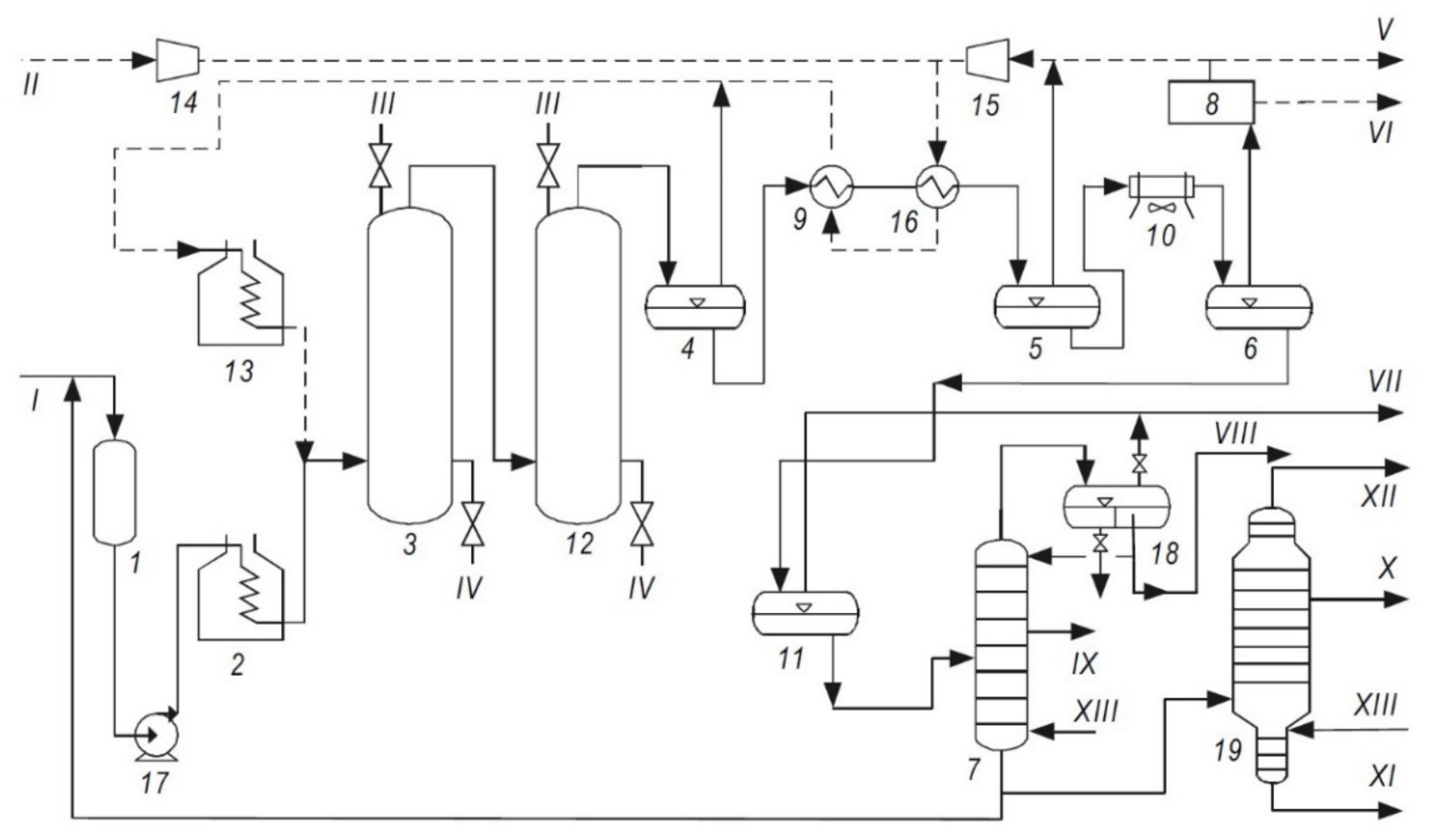
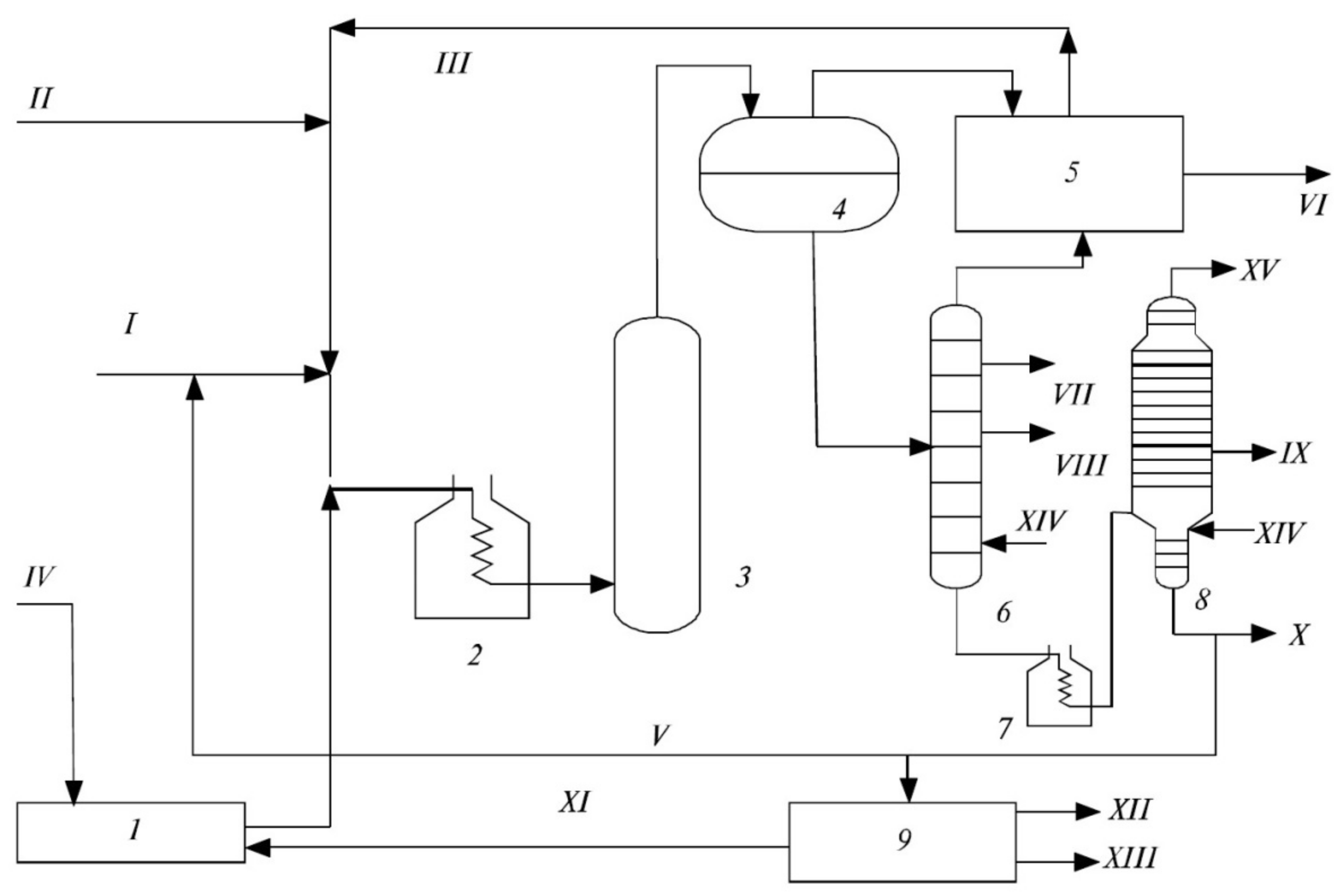
Table 1 shows the material balance of vacuum residue hydrocracking in a three-phase catalyst bed.
Figure 3 shows the functional flow diagram of the unit for catalytic three-phase fluidized-bed hydrocracking of residual stock at high pressure. Fresh and recycled content are mixed in the tank, heated in the furnace, supplied to the bottom of the catalytic three-phase fluidized-bed reactor, and premixed with the flow of heated hydrogen-containing gas, and then sequentially enter the second reactor. The gas-product blend is withdrawn from the top of the second reactor and sent into separators (just before the entry, its temperature and pressure is decreased in series), and then into atmospheric and vacuum columns for separation. Demetalization, hydrofining, and hydrocracking are carried out in the reactors. Separation of hydrogen-containing gas, hydrocarbon gases, and partially light products takes place in the separator system. Hydrogen-containing gas is refined from hydrogen sulfide, mixed with fresh hydrogen, and sent back into the system. The atmospheric column extracts gasoline, kerosene, and diesel fraction from the liquids yielded. Then the residue is partially sent to the reactor as to recycle, and the rest is sent to the vacuum column where heavy gas oil and residue are extracted.
The H-OH unit allows the process to derive up to 40% (mass) of the diesel fraction and max. 44% of the fuel oil component containing max. 1% (mass) of sulfur from the vacuum residue (>525 °C). The short residuum can contribute up to 72 % (mass) of the diesel fraction with up to 0.05 % (mass) of sulfur [
41].
The benefits of the technologies for oil stock hydrogenation upgrading in moving-bed three-phase reactors are evident. But their wide introduction is limited by a reliability loss caused by structural complexity and bulkiness of the reactors, as well as by the complexity of the process control. Since molecular hydrogen consumption is extremely high, it is necessary to put extra hydrogen production facilities into operation. The process also requires regular replacement of the catalytic system that affects the economics of the process and brings forth a problem of carbonic oxide disposal.
4. Deep Hydrocracking Processes
Lately, some companies have developed new technologies for deep residual stock hydrocracking. These technologies use fine-dispersed catalysts (the catalyst particles are reduced to nanosizes or dissolved in the stock entirely), which are introduced into the oil stock, then heated to a temperature of 350–450 °C in the furnace and sent to the reactor at a pressure of 7–15 MPa in the presence of hydrogen. Next, the gas-product blend is separated in the distillation column into reaction products and catalyst-containing residue, which is sent for recycling or removal from the unit. Basic approaches and progress in the transition theory and oil-dispersal systems being used in the above technologies make it possible to control and slow down coke formation through asphaltene stabilization with aromatic hydrocarbons and application of catalysts, physically preventing mesophase coalescence.
The processes based on different versions of hydrocracking in the presence of slurry nanosized catalysts have been presented by Foster Wheeler (USA) jointly with UOP (aquaconversion); Axens (France) jointly with PDVSA (Venezuela) and UOP (Uniflex); Russian Institute of Petrochemical Synthesis RAS (INGhS RAS) (Russian slurry hydroconversion); Eni (Italy); and KBR (Veba Combi-Cracker).
Let us consider some of these technologies that are the most developed at present.
Hydrovisbreaking-aquaconversion (Intevep SA and UOP) allows the obtaining of hydrogen from water under visbreaking due to into-stock introduction of water (vapor) and base-metal-based composition of two catalysts. Aquaconversion provides for a considerably greater viscosity reduction in the heaviest fuel oil components at higher stock conversion. Priority for slurry hydrocracking of petroleum residua was given to Canmet (Canada). At the start of XXI, the company sold its technology to UOP; later the technology was modified and called Uniflex.
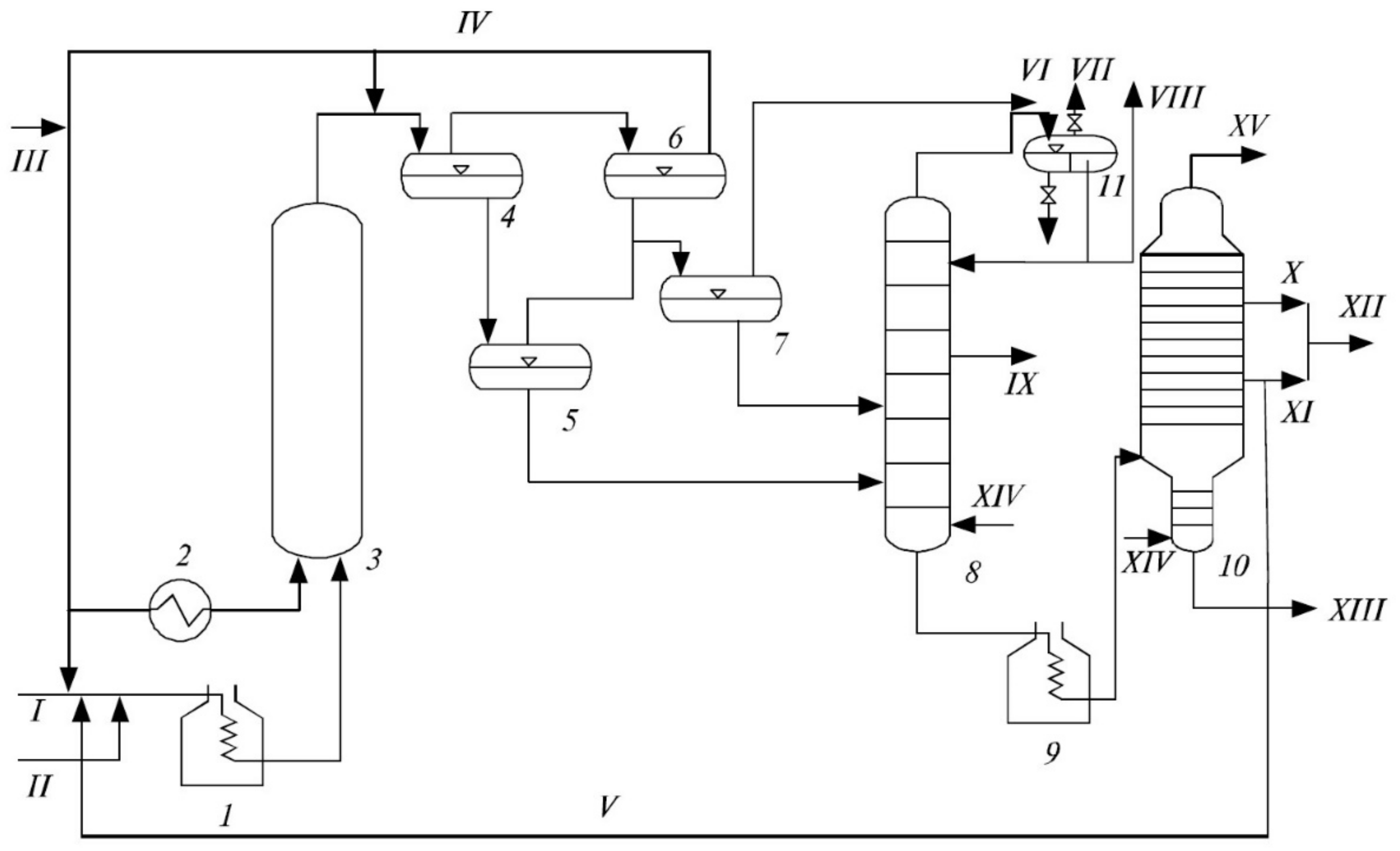
The flow chart of Uniflex is shown in
Figure 4.
Table 2 shows the material balance of Uniflex.
The stock is mixed with the required quantity of slurry catalyst and hydrogen, heated in the furnace, and introduced into the reactor, where preheated hydrogen-containing gas is delivered. The hydrocracking process is carried out at a temperature of 435–470 °C and pressure of 12.0–14.0 Mpa. Reaction products leaving the reactor pass through a number of hot separators for recovery of hydrogen-containing and separation gases, after which they enter the column for extraction of hydrocarbon gas, naphtha, and diesel fractions. The fraction that evaporates at a temperature > 350 °C is removed from the bottom of the fractional column, heated, and sent to the vacuum column for recovery of vacuum gas oil and untransformed residue (pitch). Pitch can be used as a fuel replacement in the plants that use heavy liquid residua or solid fuel as a fuel (coal gasification units, cement furnaces, etc.). Heavy vacuum gas oil is partially sent back into the reactor for further conversion, and with the quantity of high-boiling vacuum gas oil components being reduced, the light-product yields increase. A balanced quantity of heavy gas oil is mixed with light gas oil. The basic Uniflex apparatus is the upflow reactor. The stock distribution tray installed at the reactor bottom provides for intense reverse mixing without any additional devices or pumps. Since such reverse mixing establishes conditions close to isothermal, the whole reactor can operate at the higher temperature required for maximum conversion of vacuum residue.
A pilot installation was used for the process testing. This Uniflex option suggested iron compounds to be used as a catalyst and introduced into the stock in the amount of 1% mass (in terms of iron). The result was over 90% of liquids and 5–10% of residue in the form of heavy nickel and vanadium concentrate. The substantial amount of iron used as a catalyst poses transportation and disposal problems; therefore, the UOP company changed its policy and suggested the use of catalysts based on molybdenum oxides in the amount of 0.05% mass in the Uniflex process. Today, UOP has presented the hydrocracking process in a slurry-bed nanosized catalyst of a new generation—the Vacuum Residue Hydrocracking Unit—Uniflex-MC (Micro-Cat) [
42], now being implemented in China.
Variation of deep hydrocracking in a moving nanocatalyst (with molybdenum compounds) is the hydroconversion process of petroleum residua developed by the TIPS RAS specialists. Similar technology is being developed by Axens and Eni. Today, in the vicinity of Milan at the ENI refinery plant, the pilot installation with a capacity of 1 million metric tons is in successful operation using Eni slurry technology in the presence of a molybdenum catalyst containing 1% mass of molybdenum.
The innovative Russian technologies include heavy-charge hydroconversion in ultradispersed catalysts (Russian slurry hydroconversion process) developed by Topchiev (A.V.) Institute of Petrochemical Synthesis of Russian Academy of Sciences (TIPS RAS) under the leadership of academician Khadzhiyev S.N. (a member of the Academy). The Russian project of vacuum-residue hydroconversion has passed laboratory and experimental-pilot tests at TIPS RAS and at OJSC Electrogorsk Institute of refining. At present, the process is being implemented at OJSC TANECO as a pilot installation with an annual capacity of 50,000 metric tons.
The hydroconversion technology based on a completely new approach to the catalyst synthesis makes it possible to bring about revolutionary changes in the commercial refining of heavy oil feedstock. A major approach peculiarity is the refusal to use carriers in catalyst synthesis. Nanosized catalyst particles are formed in situ from the inverted emulsion of catalyst precursor. On the initiative of the technological platform “Upgrading of hydrocarbon resources” and with the support of RF Minenergo, the hydroconversion technology has been given the status of a national project.
The main distinction from any other hydrocracking processes is as follows. Molybdenum is introduced in the amount of 0.05% [
43] while the process is carried out at a pressure of 80 atm. The process has very good prospects to be used for heavy oil stock upgrading, since if applied it is possible to convert any vacuum residue into liquid oil products. It should be noted that the liquids produced require hydrorefining. Unlike DC units, the given process enables the obtaining of a high quantity of liquid oil products instead of 30% coke, while only a max. 5% accounts for residua.
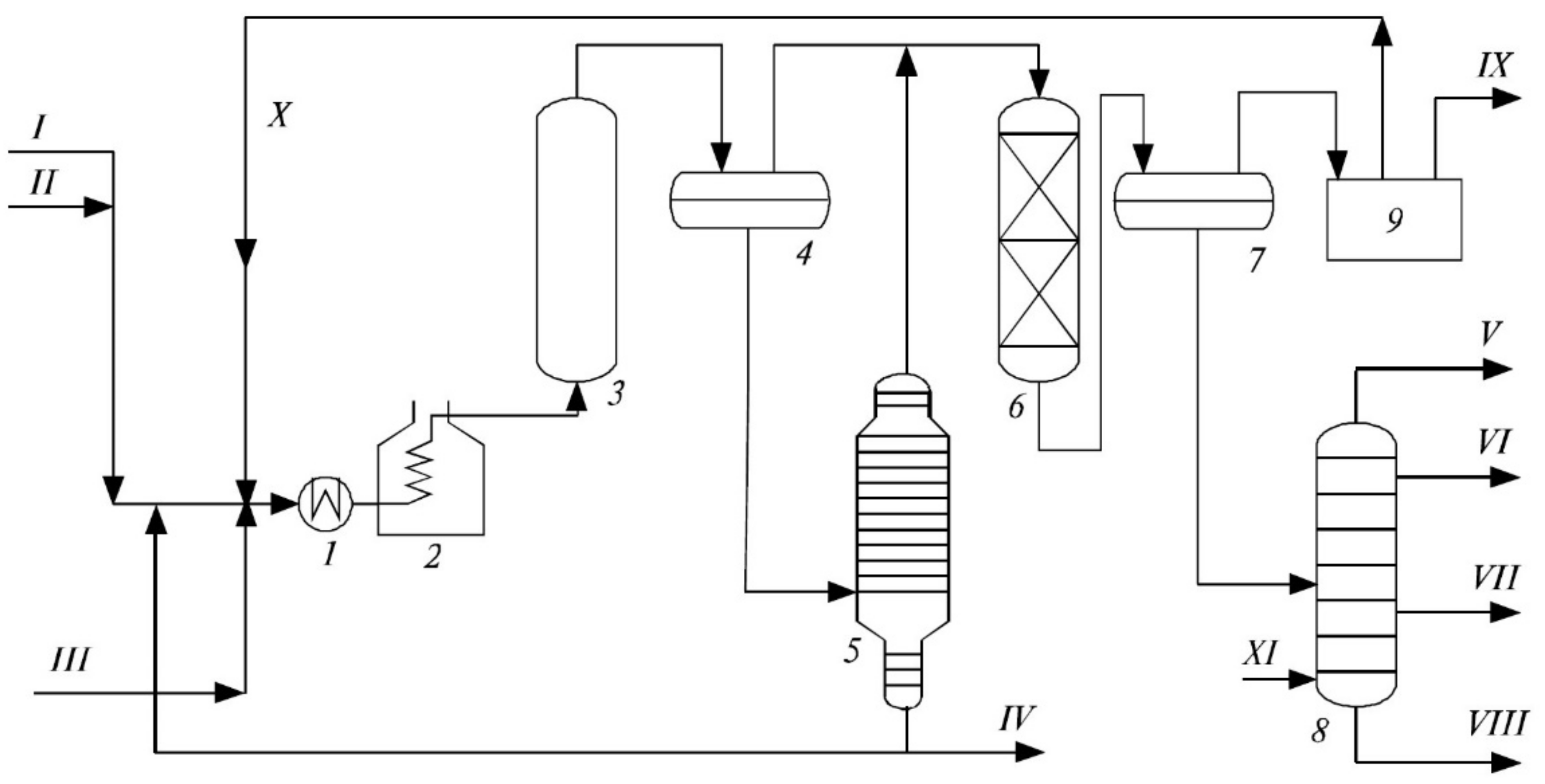
The process flow chart is shown in
Figure 5.
The catalyst consists of molybdenum compounds soluble in water. Having first been prepared in a special unit, it is injected into the stock in small quantities. There, the catalyst is in a dispersed state (sizes of catalyst particles are 100–200 nm). In this process, the suspension of nanosized molybdenum disulfide (MoS
2) particles obtained from water-soluble precursors such as ammonium paramolybdate is proposed to be used as the catalyst. The suspension of nanosized molybdenum disulfide (MoS
2) is formed from inverse precursor emulsions in a hydrocarbon medium both in interacting with sulfur-containing components of the feedstock and in reaction with specially introduced sulfiting additives of heavy-oil feedstock. The polycyclic aromatic hydrocarbon component is introduced into the system to maintain the emulsion stability and the minimum size of the suspension droplet. The particle size of the suspension depends on the size of the emulsion droplets: the smaller the emulsion droplet size, the smaller the particle size and the higher their specific surface area. The formation of the MoS
2 active phase in the reaction medium during in situ heat treatment is accompanied by the formation of supramolecular structures with asphaltene molecules, which provides effective contact between the reacting molecules and hydrogen activated on the catalyst surface during the hydroconversion process. The conditions of the hydroconversion process, the composition of the feedstock, and the conversion depth of the feedstock components, which are stabilizers of catalyst nanoparticles, significantly affect the structure, morphology, and sulfided particle size of the catalyst. The principle of obtaining concentrated suspensions of molybdenum-containing catalysts includes the stages of low-temperature (180–250 °C) and high-temperature (300–370 °C) processing. The low-temperature treatment provides the formation of the catalyst precursor, and the high-temperature stage is the key process of active catalyst formation—molybdenum disulfide of ultradispersed form. MoS
2 clusters, which consist of nanosized lamellar structures containing from one to eight layers, are formed as a result of synthesis including the stages of low-temperature and high-temperature treatment, in the presence of a sulfiding agent (sulfur) in the medium of the heavy-oil residues. Sulfur in a sulfided molybdenum-containing particle volume is concentrated mainly at the surface. Analysis of the distribution of molybdenum in the hydroconversion-process products showed that more than 90 wt % molybdenum introduced as part of the catalyst precursor binds to the asphaltenes of the feed, and the catalyst particles include molybdenum disulfide in toluene-insoluble, graphite-like organic compounds that formed during the hydroconversion process [
43].
In the hydroconversion process, the stock-catalyst mixture is added with hydrogen-containing gas, heated in the furnace up to 350–370 °C, and sent into the hydrocracking reactor, which is a hollow apparatus to carry out reactions at a pressure of 7.0–8.0 MPa and a feed-space velocity of 1.5–3.0 h−1. In the reactor, the stock moves from the bottom to the top. Next, in the separator unit, hydrogen-containing gas is separated from the gas-product blend, and then in the gas treatment unit, it is then purified from hydrogen sulfide and hydrocarbon-containing gases. The gas-product blend is sent from the separator unit into the atmospheric and vacuum columns, where it undergoes separation into hydrocarbon gas, naphtha and diesel fractions, heavy gas oil (350–500 °C), and residue in which the catalyst, asphaltenes, and heavy metals are concentrated. The residue is delivered into the catalyst regeneration unit and partially returned into the stock as a recirculator. In the regeneration unit, the residue is burned to obtain ash, which is rich in heavy metals—nickel oxides, vanadium and molybdenum. With the residue being burned, the gas is saturated with sulfur and nitrogen oxides, which can be refined to ammonia sulfate, a chemical fertilizer.
Table 3 shows quality indices of initial stock (vacuum residue) for hydroconversion.
Table 4 shows the material balance of hydroconversion for upgrading of vacuum residue from Western Siberia crude.
The process was tested using a pilot installation. Vacuum residue hydroconversion is a rather promising line of petroleum-residue upgrading. Hydroconversion distillates require additional hydro-upgrading, but on the whole, hydroconversion results in a high yield of light and vacuum distillates from oil-refining residues.
The KBR VCC (Veba Combi-Cracker) technology originates from the coal-fluidization technology developed by the German chemists F. Bergius and M. Peer in 1913. It was possible to produce liquid hydrocarbons at a temperature of 450 °C and under high pressure in the presence of hydrogen. Using this technology, which is called liquid-phase hydrogenation, 12 units were in operation in Germany from 1927 to 1944. Their total annual capacity of byproducts was 4 million metric tons of liquid hydrocarbons per year. Thermalhydrocracking was carried out at a temperature of 400–450 °C and a pressure of 30–50 MPa. After World War II, some units were transported to the USSR but have never operated as before, while the rest of them were in operation in Germany, but due to low oil prices in early 1960s, all units were brought to a stop and dismantled. It was not until 2006 that the process was born for the second time. The BP company, in cooperation with KBR, purchased the technology from VEBA OIL, and in 2009 commissioned the pilot unit in the USA. The updated technology is thermal hydrocracking in the adsorbent suspended bed. The process is aimed at upgrading of heavy-oil vacuum residue and coal to produce liquid products. With VCC, it is possible to upgrade the vacuum residue and asphalt of deasphalting, the vacuum residue of visbreaking, the heavy resin of thermal cracking, etc.
VCC is carried out in two stages: First, thermal cracking of vacuum residue is conducted in the presence of a fine-dispersed adsorbent, proceeding at an increased pressure of about 15.0–20.0 MPa in the direct-flow reactor. The feed enters at the reactor bottom and exits at the reactor top. Gases and reaction products enter the hydrocracking reactor, where the process of hydrocracking takes place in the presence of hydrogen at the same pressure of 15–20 MPa and temperature of 430–450 °C. The second stage is the hydrocracking of the vacuum residue, yielding naphtha, kerosene, jet fuel, diesel fuel, and the hydrocracking residue.
Veba Combi-Cracker residue, which leaves the direct-flow reactor at the bottom, is an asphaltene substance with a concentration of heavy metals, such as nickel and vanadium, which can be extracted and sold as highly marketable products.
Figure 6 shows the VCC simplified flowchart.
The process is carried out at a pressure of 15.0–20.0 MPa and temperature of 430–450 °C.
The stock is mixed with a fine-dispersed adsorbent (the adsorbent composition is not disclosed, but according to the inventors of the technology, it is an inert substance regarding the reaction) and then with hydrogen (circulating and added). The mixture is heated and introduced into the reactor. The process conditions (pressure, temperature, volumetric rate, and additive content) are controlled to achieve the stock treatment degree of over 95% in the direct-flow mode. The reactor has no internal components and operates in the upflow mode. Thermal cracking in the presence of hydrogen takes place in the reactor. Possible condensation reactions are delayed due to high partial hydrogen pressure. Therefore, thermohydrocracking results in the formation of light, as compared with the stock, products with a small amount of heavy residues. During the reaction, saturated compounds that hold asphaltenes split, and asphaltenes settle on the fine-dispersed adsorbent. The reaction products are directed from the reactor top to the separator, where liquid products and the adsorbent are separated from vaporous reaction products. The liquid phase is pumped from the separator into the vacuum column to extract a liquid fraction of distillates.
Liquid distillates are removed from the vacuum column with an end boiling point of 520 °C, and are then mixed with vaporous products from the separator top and sent to the second reactor to be subjected to fixed-bed hydrocracking at a pressure of 15.0–20.0 MPa.
The adsorbent-containing residue is withdrawn from the vacuum column bottom. Asphaltenes prevail in the residue. Then, the residue with the adsorbent is returned into the stock and partially removed from the system. By their quality, thermohydrocracking products can be referred to the products of thermal cracking that are to be hydrogenated, which takes place in the 2nd-stage reactor. The reaction products enter the separator from the 2nd-stage reactor bottom. From the separator, top gases are sent into the gas treatment unit, where hydrogen-containing gas is returned into the process while hydrogen-sulfide-containing gas is sent for further treatment. The liquid phase from the separator bottom is separated in the column where hydrocarbon gases C1–C4, naphtha (C5—150 °C), diesel fuel (150–370 °C), and vacuum gas oil (370–525 °C) are extracted.
Table 5 shows the product yield after vacuum-residue upgrading in two stages: thermal hydrocracking and hydrocracking, using the example of Arabian light oil.
By its quality, the naphtha produced is suitable for upgrading in the reformer. Diesel fuel with a sulfur content of less than 10 ppm meets current requirements, and vacuum gas oil is suitable for upgrading in the units of hydrocracking or catalytic cracking (FCC). All unrefined asphaltenes and metals are in the residue.
Special attention should be paid to the fact that the yield and quality of the products are given for the post-hydrocracking products. The process is active now in China. The largest unit in the world, with an annual capacity of 3.7 million metric tons per year, was built in Nizhnekamsk at JSC TAIF-NK. At present, it uses the combined feedstock (70% vacuum residue, 30% vacuum gas oil). As of today, the VCC technology is promising for the upgrading of heavy and residual feedstocks.
Table 6 shows the comparison of characteristics of modern hydrogenation processes for the processing of heavy petroleum and residual feedstock in a moving-bed catalytic.
The possibility of hydrocarbon conversion to get high-margin products using catalytic methods is limited by the need for expensive catalyst regeneration and the often high sulfur content in the feedstock. An analysis of the literature indicated that an increase in the efficiency of thermal processes of oil feedstock can be achieved using active physical (nonchemical) treatments. From a physicochemical point of view, the most promising methods of exposure are methods that allow reducing the energy consumption for the chain-initiation step, which is the most energy-intensive stage of the chain reaction of cracking [
44]. For example, such methods can include high-energy electron-beam exposure and electromagnetic radiation in the microwave spectrum.
Smart and functional materials such as biomedical nanoparticles, electronic nanostructures, and heterogeneous catalysts are often prepared in batch mode, using deposition precipitation, impregnation, colloidal, or hydrothermal methods. This leads to broad particle-size distributions, which affect the possibility of discriminating the intrinsic material’s behavior due to the lack of structural uniformity. The adoption of flow chemistry in the synthesis of nanoparticles and catalysts allows a novel process-control window.
The use of flow technologies has provided a platform for the resurgence of interest in photochemistry and electrochemistry due to a more efficient energy transfer within the narrow reaction channels. This is allowed by the easy modularity and the possibility to obtain customized reactors for every kind of reaction, solving the low homogeneity of reaction conditions, and opening up a whole range of novel and scalable transformations for the bench chemist. Examples include, among others, cycloadditions, C-C couplings, alkylation via photoredox catalysis in a flow regime, and the electrochemically-driven formation of sulfonyl fluorides, sulfoxides, and sulfones [
45,
46].
It is worth noting that the photocatalytic transformation of substrates into others by partial photocatalytic reduction or oxidation is possible. Such an approach is promising, for example, in fine organic synthesis when the final species is several times more expensive if compared with the starting substance. However, it becomes uninteresting when organizing a large-capacity process, because all the photocatalytic processes occur on the surface, not in the bulk.


