Abstract
An easy method to prepare hydrophilic PES membranes with anti-fouling properties was developed by UV-polymerization of poly vinyl pirrolidone (PVP) on membrane surfaces. The modified membrane surfaces were analyzed by ATR-FTIR, and the new hydrophilic nature of the membranes was determined by contact angle measurements. The novel membranes were prepared using Rhodiasolv® Polarclean as a green solvent and compared with a control PES membrane, without the exposure at the hydrophilization procedure. The influences of the UV lamp distance (15 and 30 cm) and the exposure time (0 cm to 60 cm) were evaluated. All membranes were characterized in terms of surface morphology, porosity, pore size, and pure water permeability (PWP). The treated membranes resulted in an increase in hydrophilicity and in improved performances in terms of PWP and foulant rejection. In particular, an anti-fouling test was performed using a solution of 100 mg/L of humic acid (HA) as a model foulant. The UV-treated membrane efficiency, compared with a commercial PES membrane, showed a recovery of about 97%, confirming that these membranes can be applied in wastewater treatment.
1. Introduction
Recently, industries are focusing on a more sustainable approach in separation processes, especially in the chemical sector, in food applications, or in processing heavily contaminated industrial wastewater. Membrane technology has become one of the most used processes, thanks to characteristics that include high efficiency, eco-friendliness, low operation, easy scalability and integration in existing processes, temperature, and energy conservation [1,2,3]. Although membrane processes possess a higher potential for water treatment, one of their major drawbacks is the fouling phenomenon. Fouling is the deposition and/or absorption on the membrane pores or surface of particles, proteins, macromolecules, particulate matter, salts, etc. [4,5]. Fouling affects flux dramatically, and degenerates membrane performance and lifespan [6,7]. Consequently, development of non-fouling membranes represents the solution to overcome this problem. Whereas the separation process is a surface phenomenon, one of the most common methods to reduce the fouling is to modify the membrane surface. In particular, hydrophilization procedures modify the membrane surface, and inhibit or minimize the fouling phenomenon because they operate at the level of surface interactions (foulant and membrane interactions) [4,8]. Membrane-surface hydrophilization is generally based on chemical and/or physical processes, with two principal approaches: (i) introduction of hydrophilic additives to dope solutions; and (ii) tailoring of the membrane surface [4,8,9,10]. Almost all membranes for industrial processes are made of organic polymers and/or inorganic materials. In particular, the polymers that are most used are: polyamide (PA), poly(vinylidene fluoride) (PVDF), polypropylene (PP), polytetrafluoroethylene (PTFE), and the family of sulfone polymers, such as polysulfone (PSF), poly(ethersulfone) (PES), and poly(phenylsulfone) (PPSU). PES is widely used for preparation of ultrafiltration (UF) and microfiltration (MF) membranes. In fact, PES offers unique peculiarity for membrane filtration applications, such as higher mechanical strength, chemical stability and caustic resistance, outstanding biocompatibility, and the possibility to produce both MF and UF hollow fibers (HFs) and flat-sheet membranes by modulating the mean pore size [11,12]. However, a disadvantage of PES membranes is their hydrophobicity, even though they present the highest water absorption rate with respect to the other commercial sulfone polymers. Several works have reported the modification of PES membranes in order to improve their hydrophilicity. The development of an asymmetric PES membrane blended with hydrophilic copolymer, which sulfonated poly (arylene ether sulfide sulfoxide sulfone) (SPAESSS), was reported by Peyravi et al. [12]. Oulad et al. [7] developed a coupling treatment of PES modified with 4,4-diaminodiphenyl sulfone, in order to create CPES/PES blended membranes with higher flux and fouling resistance properties with respect the bare PES membrane. An innovative hydrophilic and anti-fouling coating using a polymerizable bicontinuous microemulsion (PBM) for commercial PES membrane-surface modification was presented by Galiano et al. [13]. Moreover, numerous studies have mentioned the use of different nanoparticles (NPs) in order to produce PES nanocomposite antifouling membranes [14,15,16,17]. An interesting study on PES membrane performance after a modification with the addition of poly vinyl pirrolidone (PVP), UV irradiation, and thermal annealing was performed by Kusworo et al. [18]. The authors reported that the modified membrane exhibited significant enhancement of hydrophilicity and lower foulant deposition on the its surface during the biodiesel purification experiment. Pieracci et al. [19] reported the graft polymerization of N-vinyl-2-pyrrolidone on PES membranes by photolysis via UV for reducing bio-fouling. The effect of the different hydrophilic additives, such as aluminum oxide (Al2O3) NPs and polyethylene glycol (PEG), on PES membranes modified using UV irradiation was studied by Garcia-Ivars et al. [20]. An overview of UV-induced modifications of PES membranes was also presented by Ng et al. [21]. PES membranes are generally fabricated by phase inversion (PS) techniques [22]. Among these, the vapor phase, coupled to the non-solvent-induced phase separation (NIPs/VIPs), is one of the most used techniques to produce asymmetric or symmetric porous membranes. This method can modify the membrane morphology using the non-solvent (i.e., water) in vapor phase inside the climatic chamber, and modify the humidity degree, the exposure time, and the temperature. Moreover, the NIPs/VIPs technique can prevent the formation of macrovoids due to the delay of mass transfer in the climatic chamber, followed by an immersion precipitation in a coagulation bath [23]. Commonly, the preparation of a dope solution requires the solubility of a polymer in polar organic solvents, such as dimethylformamide (DMF), N-methyl-2-pyrrolidone (NMP), or dimethylacetamide (DMAc), which pose serious concerns, due to their toxic profiles, for human health and the environment [1,3,22]. Today, research focuses on the use of alternative safe and less-toxic solvents according to the fifth principle of green chemistry, as reported by Anastas [24]. Therefore, in our study, methyl-5-(dimethylamino)-2-methyl-5-oxopentanoate (Rhodiasolv® Polarclean) was chosen as a greener alternative solvent. According to the circular economy design on the use of new chemicals [25], this solvent derives from the recycling of synthesis of nylon 6,6, and presents good properties: it is not toxic, reprotoxic, or mutagenic; and it is biodegradable [26]. It has also a low vapor pressure and high boiling point (280 °C), and it is totally soluble in water, making it suitable for membrane preparation [27]. Polarclean has already been successfully proposed for the preparation of MF and UF membranes, using different polymers, e.g., PES and PVDF [28,29]. In this study, an easy procedure for improving the anti-fouling performance of PES membranes is presented. Polymeric porous PES membranes were prepared via PS technique using Polarclean as a green solvent and exposed to a UV-lamp in order to induce the PVP photopolymerization inside the membranes [30]. The nature of PVP as a hydrophilic additive was exploited. It is a hydrophilic polymer without hydroxide or ionic charged groups, and is commonly used as a pore former in a casting solution for porous membrane preparation [4,31,32,33,34,35,36]. It is also a non-toxic polymer and is commercially accessible at low cost [37]. The effects of UV-lamp distance (15 and 30 cm) and the exposure time (0 cm to 60 cm) inside the UV chamber were studied and evaluated. The success of the hydrophilization procedure was verified via ATR-FTIR and water contact angle measurements (CAw). The UV-modified membranes were studied in terms of morphology, using SEM and AFM microscopy, porosity, and pore size. Membrane performance was initially evaluated by measuring the water permeability. An anti-fouling test was conducted by using the model foulant humic acid (HA) (100 mg/L). In order to highlight the properties of the UV-modified membranes, a hydrophilic commercial PES membrane was used as model during the experiments.
2. Materials and Methods
2.1. Chemicals
The Rhodiasolv® Polarclean HSP (methyl-5-(dimethylammino)-2-methyl-5-oxopentanoate; boiling point: 278–282 °C; water solubility >490 g dm–3 at 24 °C) and polyethersulfone (Veradel® 3000P) were kindly provided by Solvay Specialty Polymers (Bollate, MI, Italy). The poly vinyl pirrolidone (PVP, Luviskol, K17; Mw=9 kg/mol and K-90; Mw = 1400 kg/mol) was purchased from BASF and desiccated under vacuum at 50 °C for 24 h before use. The polyethylene glycol (PEG-200; Mw = 0.2 Kg/mol), 2.2 Dimethoxy-2-phenylacetophenone, 2-Isopropyl alcohol ≥99.5%, Fluorinert FC-40, and humic acid (HA) were purchased from Sigma Aldrich (St. Louis, MO, USA) and used without further purification. The polyethersulfone (PES) membrane filters (0.45 µm) (PES0453001) were purchased from Sterlitech (Sterlitech corporation, Kent, WA, USA).
2.2. Polymeric Dope Solution Preparation
The polymeric dope solution was produced by dissolving 11 wt.% of the polymer in the correct amount of solvent Polarclean. Subsequently, the 25 wt.% of PEG-200 was added, and after few minutes, 13 and 2 wt.% of PVP-K17 and K-90, respectively, were added to complete the solution. Only in the case of UV treatment, the 1 wt.% of the photo-initiator (2.2 Dimethoxy-2-phenylacetophenone) was included in the dope solution. Polymeric dope was prepared at 70 °C, under constant mechanical stirring for 2 h. When the solution became homogeneous, the dope was kept at 50 °C for 3 h for degassing, before casting.
2.3. Membrane Preparation and Hydrophilization Procedure
The membranes were fabricated via the PS method by casting the polymeric solution at 50 °C on the glass plate using a knife with a gap of 250 µm within a climatic room (DeltaE srl, Rende, CS, Italy). The nascent membranes were exposed for 2.5 min at 55 Rh% humidity and 25 °C, following immersion in the water coagulation bath. In the case of UV-treatment, after the exposure time to humidity in the climatic chamber, the nascent membrane was exposed to a UV lamp (500 W; purchased from Helios Italquartz Production Site/R&D and Technical Center, Cambiago, MI, Italy). It presented an emission spectrum from 180 nm to visible light. The effects of lamp distance and exposure time were studied; in particular, the lamp distance (cm) was changed between 15 and 30 cm, and the exposure time to UV was varied from 0 to 60 s, as reported in Table 1.

Table 1.
Summary of the prepared membranes.
After the hydrophilization procedure, the membranes were dipped in a water coagulation bath, and washed in hot water (60 °C) three times. The obtained membranes were then dried in air, and subsequently in an oven at 40 °C overnight. The scheme of the membrane preparation and hydrophilization procedure is shown in Figure 1. In order to confirm cross-linking of PVP in the PES membranes, the membranes were soaked in a solution of sodium hypochlorite (NaOCl) at 400 ppm and pH = 7 for 24 h at room temperature.
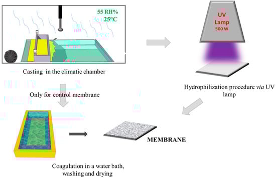
Figure 1.
A simplified scheme of the membrane preparation.
2.4. Viscosity Measurement
The viscosity of the polymeric solutions was measured by employing a rotational rheometer (Brookfield, DV-III Ultra, Toronto, ON, Canada) equipped with a thermostatic bath. The data were acquired as a function of temperature (between 30 and 70 °C), selecting the proper shear rate in order to be within the Newtonian regime and torque value (between 10 and 90% of the maximum value). The measurement was repeated three times. The spindle used was an SC4-34.
2.5. Attenuated Total Reflectance Fourier Transform Infrared Spectroscopy (ATR-FTIR)
The membrane surfaces were analyzed using ATR-FTIR. Ten different points in the sampling area were analyzed, and the resulting spectra, at a resolution of 4 cm−1, were acquired at the same pressure with a micrometer torque (UATR crystal Diamond/ZnSe–Spectrum One System, Perkin Elmer Instruments, Waltham, MA, USA). The depth of penetration was up to 1.66 µm.
2.6. Scanning Electron Microscopy (SEM)
A Zeiss EVO MA100 scanning electron microscope (Zeiss, Assing, Roma, RM, Italy) was used in order to study the membranes’ morphology (cross-section, top and bottom side). Cross-section samples were obtained by freezing the membrane in liquid nitrogen and then fracturing it [38]. All samples were sputter-coated with a thin gold film prior to SEM observation (Q150R S, Quorum Technologies Ltd., Lewes, UK).
2.7. Atomic Force Microscopy (AFM)
A Bruker Multimode 8 combined with Nanoscope V controller was employed to investigate the topography of the membranes via AFM. The data were acquired in tapping mode, using silicon cantilevers (model TAP150, Bruker, Karlsruhe, Germany). The pictures of the membrane surfaces were imaged at a scan size of 10 μm × 10 μm. Five measurements were taken in different points of the sample. The average and standard deviation have been reported.
2.8. Thickness
The membranes’ thickness was measured using a digital micrometer (Carl Mahr, Gottingen, Germany, ±0.001 mm of precision). Specifically, membrane thickness was registered in ten regions of the membrane. The average value and standard deviation were calculated.
2.9. Porosity
A membranes’ porosity (ɛ) is the volume of the voids inside the membrane divided by its total volume. Porosity was calculated using the gravimetric method, according to the literature [39]. The method involves weighing the dry membrane samples and subsequently weighing the wet membrane samples after the impregnation in IPA for 24 h. Porosity was calculated as:
where Ww and Wd are the weight of the wet and dry membranes, respectively, ρi is the IPA (0.78 g/cm3), and ρP is the polymer density (1.37 g/cm3). For all samples, the measurement was repeated three times, and the average and corresponding standard deviation were calculated.
2.10. Pore Size
An analysis of bubble point and pore size was performed using a PMI capillary flow porometer (CFP1500 AEXL, Porous Materials Inc., Ithaca, NY, USA), in a wet-up/dry-up operating mode. The data were analyzed using the software Capwin. Each membrane sample was initially immersed and wetted for 24 h using Fluorinert FC-40 (16 dyne/cm). For each membrane, three measurements were taken. The average and the standard deviation were calculated.
2.11. Contact Angle
A CAM 200 contact angle meter (KSV Instruments LTD, Helsinki, Finland) was utilized to study the hydrophilic nature of the membranes. A drop of 5 µL of ultrapure water was used for the measurements. The data was acquired five times, and the average and the corresponding standard deviations have been reported.
2.12. Pure Water Permeability
A pure water permeability (PWP) test was performed using a cross-flow cell (DeltaE srl, Milan, MI, Italy) equipped with a gear pump (Tuthill Pump Co., Concord, CA, USA). The effective active area of the membrane was 8 cm2, and the experiments were conducted at room temperature (25 °C). Before the permeability tests, the membrane was conditioned for 30 min at a trans-membrane pressure of 1 bar. The membrane was exposed at three different transmembrane pressures (0.85/0.65/0.45 bar), separated by a stabilization period of 15 min. The permeate was collected at 60 s. The PWP was calculated according to this equation:
where A is the membrane area (m2); p is the pressure (bar); Q is the permeate volume (L); and t is the time (hours). The PWP test was repeated three times, and the average was reported with its corresponding standard deviation.
PWP = Q/A t p
2.13. Anti-Fouling Tests
HA, at 100 mg/L, was used as model foulant for the fouling tests. The permeability (PHA) was measured three times and evaluated at steady-state conditions. The fouling test was repeated three times on the same sample (six hours for each test). Between fouling tests, the membrane was washed with ultrapure water at 0.25 bar for 3 h, and the pure water permeability (PWN) was evaluated again. The reduction and recovery in the PWP were calculated as follows:
Reduction (%) = (1 − PHA/PW*100)
Recovery (%) = ((PWN − PHA/PHA)*100)
During the HA permeability tests, the absorbance of the feed and permeate solutions were measured with a UV-160 A spectrophotometer (Shimadzu Scientific Instruments, Inc., Tokyo, Japan). A calibration curve, using reference compounds of known concentration (0-30-60-90-100-120 mg/L of HA), was created. The absorbance of the resulting solutions was measured at 254 nm (final concentration of HA equal to 0, 0.60, 1.19, 1.69, 1.75, 1.92 Abs) in order to obtain from the equation of the line (y = 0.0184x), the value of the correlation coefficient (R2 = 0.9909), the slope, and the intercept, using the least squares method.
Rejection (R%) was then calculated using the following equation:
where Cf and Cp are the concentrations (expressed in mg/L) of feed and permeate, respectively.
R(%) = ((Cf − Cp)/Cf)*100
Three anti-fouling tests were performed for each sample; the average and the standard deviation were calculated and reported.
3. Results and Discussion
The hydrophilization procedure is a simple and direct process for modifying PES membranes using a UV process. UV light is radiated onto the nascent membrane while the membrane is in the presence of PVP, a hydrophilic polymer. This easy procedure promotes the attachment of free radically polymerizable hydrophilic compounds onto the surface of the membranes, according to literature [19,30,35]. In our work, the hydrophilization of the membrane surface occurs through UV irradiation and thermal annealing [18,35]. On one hand, the UV irradiation promotes the cross-linking of PVP, forming an interpenetrating polymeric network by using a suitable polymerizable photoinitiator, such as 2.2 Dimethoxy-2-phenylacetophenone (DMPA) [40]. The UV can induce the degradation of DMPA in a radical segment in order to obtain a grafted PVP PES membrane [41]. The reaction of the radical with the PVP can generate macroradicals centered in three possible positions, as reported by Parisi et al. [42] and by Zhu et al. [43], that can be grafted onto the PES membrane, considering the lability of the hydrogen atoms present in its structure. On the other hand, according to Allegrezza et al. [35], the membrane surface should hydrophilize due to the thermal annealing condition (80 °C) created in the UV chamber during polymerization. Thermal annealing can cause the rearrangement of membrane molecules, with a modification of surface membrane in terms of performance.
3.1. ATR-FTIR
According to the hydrophilization procedure, the nascent membrane, prepared using a photoinitiator (2.2-Dimethoxy-2-phenylacetophenone), was exposed to a UV lamp. This procedure was necessary to enhance the polymerization of the PVP inside the membrane. The IR spectra (Figure 2a,b) confirmed the presence of polymerized PVP in the UV-M15-15 membrane, showing a characteristic peak at 1665 cm−1. This peak represents the stretching of the ketonic C=O band. The UV-M15-15 membrane spectra also showed the presence of the photoinitiator, with a peak at 1729 cm−1. On the contrary, in the UV-M0 membrane (without the hydrophilization procedure) the peak of PVP was not particularly evident, confirming the potential of the UV method. Furthermore, when examining the spectra of the UV-M15-15 membrane with the chemical cleaning of NaClO reported in Figure 2c, it is possible to notice that the peak of the PVP was the same intensity of the membrane UV-M15-15 peak without the NaClO treatment (Figure 2a). It is well known that the action of NaOCl can leach out PVP or other additives from membrane pores [44,45]. In our study, the NaOCl treatment determined a control role on the PVP cross-linking, which remained inside the membrane. The peaks, around 1576 cm−1 and 1485 cm−1, identified the stretching vibration of the C=C skeleton in an aromatic ring. The peak presented at 1240 cm−1 was the absorbance of C–O–C bond of the PES. The bands at 1148 cm−1 and 1103 cm−1 can be attributed to the sulfone group, while the peak at 1083 cm−1 can be attributed to the stretching vibration of –C–O.
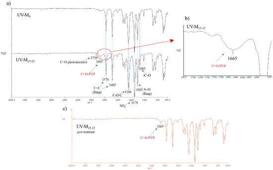
Figure 2.
(a) ATR-FTIR spectra of UV-M0 and UV-M15-15 PES membranes; (b) spectra magnification of the UV-M15-15 PES membranes (from 1807 to 1557 cm−1), and (c) ATR-FTIR spectra of UV-M15-15 PES membranes after NaClO treatment.
3.2. Membrane Morphology and Properties
3.2.1. SEM
Figure 3 shows the SEM pictures of the membranes prepared with and without the hydrophilization procedure. All membranes presented an asymmetric structure in which the selective layer is thin and porous, over a much thicker porous sub-structure, according to the literature [32]. The UV-M0 membrane prepared without the exposure time to the UV lamp and only to humidity in the climatic chamber, also showed a porous structure in the top, bottom, and cross-section surfaces. In this case, the presence of PVP confirmed its nature as a pore-forming agent of the membrane structure [46]. PVP has high miscibility with PES and high solubility in water, as a non-solvent, in the coagulation bath [47]. The combination of the NIPs/VIPs technique with hydrophilic agents at high molecular weight in the polymeric solution led to a slow polymer precipitation, causing a retarded interchange exchange between the solvent and non-solvent, preventing finger-like macrovoid formation, promoting homogenous sponge like structures, and increasing hydrophilicity [29,48,49]. The nascent membrane prepared according to Section 2.4, after humidity, was exposed to a UV lamp (500 W), and the effects of lamp distance and exposure time (15 and 60 s) were studied. The distance from the lamp to the membranes was varied from 15 to 30 cm, as reported in Table 1. The temperature inside the UV chamber was maintained stable by using cooling fans.
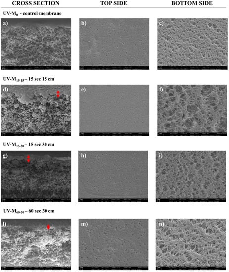
Figure 3.
SEM images (cross-section, top side, and bottom side) of the (a–c) UV-M0 control membrane; (d–f) UV-M15-15 membrane; (g–i) UV-M15-30 membrane; and (l–n) UV-M60-30 membrane (magnification of 5.00 KX for cross-section and top side, and 10.00 KX for bottom side).
The effect of UV irradiation on PES membranes has been reported by Yamagishi et al. [50]. According to this study, the PES polymer presented high photosensitivity, and the UV exposure led to a split of the primary bond of the polymer chain, with a consequent reduction in the molecular weight. Figure 3 shows:
- -
- A sponge-like structure for all membranes produced (Figure 3a,d,g,l).
- -
- The top side of the membrane exposed for 60 s (UV-M60-30) appears more porous (Figure 3m) than the top side (Figure 3b) of the control membrane (UV-M0). The opposite trend was observed for the membranes exposed for 15 s for UV-M15-15 (Figure 3e) and for UV-M15-30 (Figure 3h). The selective layer was similar for the UV-M15-15 and UV-M15-30 membranes (Figure 3d,g) while it decreased for the UV-M60-30 membrane (Figure 3l).
- -
Similar results were obtained by Roesink H.D.W. et al. [51]. After cross-linking of the hydrophilic polymer (PVP), they obtained a stable polymer matrix with membrane surface that was very smooth and with less fouling. No images were reported for the membrane UV-M60-15. In fact, the UV treatment for 60 s at 15 cm of lamp distance damaged the surface. For this reason, the membrane UV-M60-15 was not characterized.
3.2.2. Viscosity, Thickness, Porosity, Pore Size, and Pure Water Permeability
Features of the membranes are summarized in Table 2. When comparing the thickness of the control membrane (UV-M0), it was observed that in all cases, the thickness decreased after the UV procedure.
Table 2.
Features of the membranes prepared.
Viscosity, as reported in Figure 4 (changed by polymer molecular weight), plays a crucial role during membrane formation, influencing the thermodynamics and kinetics of the phase separation [52,53]. It must be considered that during the hydrophilization procedure, the temperature inside the UV chamber was 40 °C, while the temperature inside the climatic room was 25 °C. Therefore, this increase in temperature also resulted in a viscosity reduction. In fact, a lower thickness was observed for the membrane exposed for 15 s at 15 cm from the UV lamp (membrane UV-M15-15). The membranes exposed for 30 s presented a thickness reduction of 12% and 17% for the membranes UV-M15-30 and UV-M60-30, respectively.
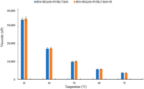
Figure 4.
Viscosity of the polymeric dope solutions.
Porosity decreased for the UV-M15-15 and UV-M15-30 membranes due to an increase in the selective layer, as shown by the SEM images. Moreover, a higher increase in terms of porosity and pore size was observed for the UV-M60-30 membrane. This result was also in agreement with the SEM images; in fact, only the surface of the membrane exposed to the UV lamp for 60 s appeared more porous, with a thinner selective layer. Finally, when the UV exposure time was fixed at 15 s, the pore size increased from 14 to 17%, when the lamp distance was 15 and 30 cm, respectively. Concerning the pure water permeability (PWP) results, it is possible to observe an increase for all the investigated membranes, according to the previous data. In particular, a higher flux was reported for the UV-M60-30 membrane (35,418 L/m2h bar) due to the higher pore size and porosity. Interestingly, the flux obtained for the membrane prepared at 15 s (UV- M15-15) was about 25,000 L/m2h bar. This result was in accordance with the decrease in thickness (85.4 µm) and pore size (0.43 µm).
3.2.3. Water Contact Angle
The water contact angle (CAw) measurements of the membranes, with and without the hydrophilization procedure, are reported in Figure 5. The CAw was less than 55°, indicating the hydrophilic nature of the membranes in all cases.
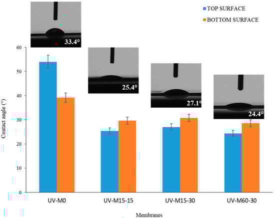
Figure 5.
The CAw of the membranes with and without the UV hydrophilization procedure.
The control membrane (UV-M0) presented an average CAw of 54 ± 0.5, while the membranes exposed to the hydrophilization procedure showed a CAw of less than 30°. This result indicates that the hydrophilic treatment decreased the Caw and enhanced the hydrophilic nature of the membranes, thereby enhancing their performance in terms of water permeability. Theoretically, the adsorption and deposition of hydrophobic pollutants onto the membrane surface should be reduced [54]. It was observed (Figure 5) that all membranes prepared by UV treatment exhibited less difference between top and bottom surfaces compared to the UV-M0, with slightly higher values for the bottom. This can be attributed to the membrane surface roughness and a more porous bottom surface, which, according to the model of Cassie-Baxter [55], reduces the surface area in contact with water, as a consequence of the air trapped in the membrane pores.
3.2.4. Commercial PES Membrane Properties
In order to evaluate whether the proposed hydrophilic procedure really improved the membranes’ performance, a commercial PES membrane was employed as reference. This membrane was characterized in terms of morphology, thickness, CAw, porosity and pore size. Table 3 shows the results of the characterization tests for the commercial PES membrane.
Table 3.
Commercial PES membrane properties.
The SEM analysis confirmed the sponge-like morphology of the membrane, visible in the cross-section, with porous top and bottom surfaces (Figure 6).
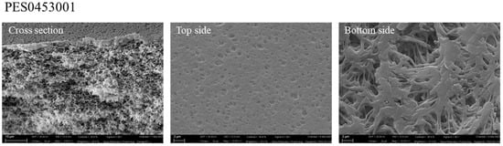
Figure 6.
SEM picture of the commercial PES membrane (magnification of 4.00 KX for cross-section and top side, and 10.00 KX for bottom side).
3.2.5. Anti-Fouling Tests
According to the membrane morphology and properties results, the UV-M15-15 membrane was selected for the anti-fouling test. In particular, anti-fouling properties were evaluated by using the model foulant HA, as reported in Section 2.12.
The obtained data are presented and compared in Table 4.
Table 4.
The permeability and anti-fouling properties of the UV-M15-15 and commercial PES membranes.
The selected PES commercial membrane was characterized by the same porosity and pore size (Table 3) of the prepared UV-M15-15 membrane (Table 2). The high value of PWP for the membrane UV-M15-15 (25,301 L/m2h bar) with respect to the commercial membrane (18,482 L/m2h bar) was principally associated with the lower thickness (about 105 µm) and contact angle (25° and 30° for top and bottom sides, respectively).
As reported in Table 4, the UV-M15-15 membrane presented an initial PWP higher than the commercial PES membrane. During the experiment with HA, a reduction of around 97% was observed for both the membranes. A rejection (R%) of about 92.95 and 93.50 % was found for the UV-M15-15 and commercial PES membranes, respectively (Table 5). A comparison of these membranes’ performance with other studies presented in literature is reported in Table 5. It is well known from the literature that the anti-fouling performance of a membrane is strongly influenced by its surface properties, such as surface hydrophilicity, roughness, and as a consequence, the preparation method of the membrane. The membranes produced with hydrophilic character and smooth surfaces seem to possess good rejection to foulant, as reported by Vatsha et al. [56]. In this study, the trade-off between flux and rejection was represented by 90% of BSA protein rejection. Similar rejection efficiency (91%) was obtained in the work of Kusworo et al. [18] for PES-ZnO membranes with PVP modified by UV irradiation and thermal annealing, where the ZnO was blended into the PES during the dope-solution preparation to improve the homogeneity. As described by Seman et al. [57] and Rahimpour et al. [58], the UV-initiated graft polymerization technique for PES membranes using monomer acrylic acid (AA) and N-vinylpyrrolidone (NVP) can influence the surface roughness and enhance the humid acid rejection factors (96%) and low fouling tendency. In previous studies, the effect of UV light on the homogeneous solution of PSF membranes with methylacrylate (MA) monomer have been discussed. The results demonstrated that at a low degree of hydrophilicity (51°), it is possible to obtain a major permeation of the BSA solution, confirming the antifouling property of the membranes [59].
Table 5.
Features of the prepared PES membranes in this work and from literature according to hydrophilization UV procedure.
Very promising results on recovery in PWP after membrane HA tests were registered. The structure of the cleaned membrane was shown by SEM analysis. Figure 7 illustrates the morphology (cross-section, top, and bottom surfaces), after three tests with HA, and after water-cleaning treatment. The cleaned membrane showed again similar structure to the pristine one in the cross-section (Figure 3d), indicating an effective aging resistance to the membranes. The top and bottom surface morphology (Figure 7b,c) revealed a thin deposit of fouling with a more closed structure. In fact, membrane UV-M15-15 was able to recover its original performance, with a recovery of 97.5% and a permeability flux of 25,180 L/m2h bar (Table 4).
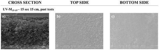
Figure 7.
SEM pictures of the UV-M15-15 PES membrane after tests of HA rejection and cleaning with magnification of 4.00 KX for (a) cross-section and (b) top side, and magnification of 10.00 KX for (c) bottom side.
On the contrary, the commercial PES membrane presented a recovery of about 2.70%, confirming the lower propensity of UV-M15-15 membrane to be affected by fouling due to its enhanced hydrophilic properties [13,19].
3.3. AFM Analysis
An in-depth analysis of the UV-M15-15 and commercial PES membranes’ surfaces, before and after the anti-fouling experiment, was performed using AFM. The data are reported in Table 6.
Table 6.
Surface roughness of UV-M15-15 and commercial PES membranes, before and after the anti-fouling experiment.
The roughness average (Sa) was obtained from the deviations of the center line within the evaluation length. The root mean square roughness (RMS, Sq) is the average of height deviations from the mean image plane, and it is expressed as:
where zi is the height measured at each point of the image, is the height average, and N is the number of the points. The peak-to-peak distance (Sz) is the average difference between the height of the highest peaks and the valley of the plane.
Considering the images and data reported in Figure 8 and Table 6, respectively, we observed that before the anti-fouling experiment, the commercial PES membrane presented a smooth surface compared to the UV-M15-15 membrane. On the contrary, after the anti-fouling experiment, in all cases the roughness increased. It is interesting to note that for the UV-M15-15 membrane, the roughness (Sq) increased only 20%, while for the commercial PES membrane, an increase of 95% was registered.
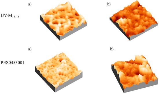
Figure 8.
AFM images of the UV-M15-15 and PES0453001 membranes, (a) before and (b) after the anti-fouling experiments.
Surface roughness is one of the properties that influences membrane performance during water filtration [60]. Despite several studies reporting that the particle adhesion increases in relation to the higher surface roughness, and therefore a smooth surface is preferred [13,60,61], the real correlation between the surface roughness and membrane performance is controversial [4]. As reported by Riedl et al. [62], smooth membranes produce a dense surface fouling layer, while rough surfaces produced a more open fouling layer. According to this study, the roughness measurements confirmed the observed recovery and permeation data. In fact, the high roughness increased the water flux of the membranes [63,64].
4. Conclusions
An easy procedure to produce anti-fouling PES membranes was presented. The nascent PES membranes were modified by UV-polymerization, inducing the cross-linking of the hydrophilic PVP additive on the membrane surface. Two variables during the hydrophilization procedure were considered: UV exposure time (15 and 60 s) and distance between membrane and UV lamp (15 and 30 cm). The produced membranes presented porous asymmetric structure with a thin selective top layer and a much thicker porous sublayer. The UV treated membranes showed an enhanced hydrophilicity, with a CAw decreasing from 54° to 24°, resulting in better performances in terms of water permeability, with a maximum value of about 25,000 L/m2h bar. The success of the procedure was confirmed by the anti-fouling experiments conducted using HA as the model foulant. The UV-treated membranes showed a significant improvement in performance with respect to the commercial membranes. The obtained results show the UV-membranes were capable of recuperating their original performance after the HA test, with a recovery of about 97%, confirming that the hydrophilization procedure improved the membranes’ anti-fouling surface properties, reducing the adsorption and deposition of pollutants, and promoting the formation of reversible fouling.
Author Contributions
Conceptualization: A.F., C.U. and E.D.N.; methodology: A.F., E.D.N. and C.U.; investigation: A.F., C.U., F.R. and M.B.; writing—original draft preparation: A.F., C.U. and F.R.; writing—review and editing: A.F., C.U., F.R. and E.D.N.; visualization: A.F., C.U. and E.D.N.; supervision: A.F. and E.D.N.; project administration: A.F. All authors have read and agreed to the published version of the manuscript.
Funding
This research received no external funding.
Institutional Review Board Statement
Not applicable.
Informed Consent Statement
Not applicable.
Data Availability Statement
Not applicable.
Conflicts of Interest
The authors declare no conflict of interest.
References
- Figoli, A.; Marino, T.; Simone, S.; Di Nicolò, E.; Li, X.-M.; He, T.; Tornaghi, S.; Drioli, E. Towards non-toxic solvents for membrane preparation: A review. Green Chem. 2014, 16, 4034. [Google Scholar] [CrossRef]
- Fane, A.G.; Tang, C.Y.; Wang, R. Membrane Technology for Water: Microfiltration, Ultrafiltration, Nanofiltration, and Reverse Osmosis. In Treatise on Water Science; Wilderer, P., Ed.; Elsevier Science: Amsterdam, The Netherlands, 2011; Volume 4, pp. 301–335. ISBN 978-0-444-53199-5. [Google Scholar]
- Russo, F.; Ursino, C.; Avruscio, E.; Desiderio, G.; Perrone, A.; Santoro, S.; Galiano, F.; Figoli, A. Innovative Poly (Vinylidene Fluoride) (PVDF) Electrospun Nanofiber Membrane Preparation Using DMSO as a Low Toxicity Solvent. Membranes 2020, 10, 36. [Google Scholar] [CrossRef] [PubMed]
- Rana, D.; Matsuura, T. Surface modifications for antifouling membranes. Chem. Rev. 2010, 110, 2448–2471. [Google Scholar] [CrossRef] [PubMed]
- Baker, R.W. Membrane Technology and Applications; John Wiley & Sons, Ltd.: London, UK, 2004; ISBN 0470854456. [Google Scholar]
- Noble, R.D.; Stern, S.A. Membrane Separations Technology—Principles and Applications, 3rd ed.; Elsevier Science: Amsterdam, The Netherlands, 1995; ISBN 9780080536187. [Google Scholar]
- Oulad, F.; Zinadini, S.; Zinatizadeh, A.A.; Derakhshan, A.A. Novel (4,4-diaminodiphenyl sulfone coupling modified PES/PES) mixed matrix nanofiltration membranes with high permeability and anti-fouling property. Sep. Purif. Technol. 2020, 236, 116292. [Google Scholar] [CrossRef]
- Figoli, A.; Ursino, C.; Galiano, F. Innovative coating membranes for water treatment. In Functional Nanostractured Membranes; Drioli, E., Giorno, L., Gugliuzza, A., Eds.; Pan Stanford: Singapore, 2018; p. 604. ISBN 978-981-4774-79-6. [Google Scholar]
- Drioli, E.; Giorno, L. Membrane Operations: Innovative Separations and Transformations; Wiley-VCH: Weinheim, Germany, 2009; ISBN 9783527320387. [Google Scholar]
- Bildyukevich, A.V.; Plisko, T.V.; Liubimova, A.S.; Volkov, V.V.; Usosky, V.V. Hydrophilization of polysulfone hollow fiber membranes via addition of polyvinylpyrrolidone to the bore fluid. J. Membr. Sci. 2017, 524, 537–549. [Google Scholar] [CrossRef]
- Solvay. Processing Guide for Polymer Membranes. Available online: https://www.solvay.com/sites/g/files/srpend221/files/2018-08/Membranes-Processing-Guide_EN-v4.6_0.pdf (accessed on 20 November 2020).
- Peyravi, M.; Rahimpour, A.; Jahanshahi, M.; Javadi, A.; Shockravi, A. Tailoring the surface properties of PES ultrafiltration membranes to reduce the fouling resistance using synthesized hydrophilic copolymer. Microporous Mesoporous Mater. 2012, 160, 114–125. [Google Scholar] [CrossRef]
- Galiano, F.; Figoli, A.; Deowan, S.A.; Johnson, D.; Altinkaya, S.A.; Veltri, L.; De Luca, G.; Mancuso, R.; Hilal, N.; Gabriele, B.; et al. A step forward to a more efficient wastewater treatment by membrane surface modification via polymerizable bicontinuous microemulsion. J. Membr. Sci. 2015, 482, 103–114. [Google Scholar] [CrossRef]
- Ursino, C.; Castro-Muñoz, R.; Drioli, E.; Gzara, L.; Albeirutty, M.H.; Figoli, A. Progress of nanocomposite membranes for water treatment. Membranes 2018, 8, 18. [Google Scholar] [CrossRef]
- Kumari, P.; Modi, A.; Bellare, J. Enhanced flux and antifouling property on municipal wastewater of polyethersulfone hollow fiber membranes by embedding carboxylated multi-walled carbon nanotubes and a vitamin E derivative. Sep. Purif. Technol. 2020, 235, 116199. [Google Scholar] [CrossRef]
- Susanto, H.; Desiriani, R.; Adi, A.; Hermita, D. Incorporation of Nanoparticles as Antifouling Agents into PES UF Membrane. Mater. Today Proc. 2019, 13, 217–223. [Google Scholar] [CrossRef]
- Esfahani, M.R.; Aktij, S.A.; Dabaghian, Z.; Firouzjaei, M.D.; Rahimpour, A.; Eke, J.; Escobar, I.C.; Abolhassani, M.; Greenlee, L.F.; Esfahani, A.R.; et al. Nanocomposite membranes for water separation and purification: Fabrication, modification, and applications. Sep. Purif. Technol. 2019, 213, 465–499. [Google Scholar] [CrossRef]
- Kusworo, T.D.; Widayat, W.; Utomo, D.P.; Pratama, Y.H.S.; Arianti, R.A.V. Performance evaluation of modified nanohybrid membrane polyethersulfone-nano ZnO (PES-nano ZnO) using three combination effect of PVP, irradiation of ultraviolet and thermal for biodiesel purification. Renew. Energy 2020, 148, 935–945. [Google Scholar] [CrossRef]
- Pieracci, J.; Crivello, J.V.; Belfort, G. Photochemical modification of 10kDa polyethersulfone ultrafiltration membranes for reduction of biofouling. J. Membr. Sci. 1999, 156, 223–240. [Google Scholar] [CrossRef]
- Garcia-Ivars, J.; Iborra-Clar, M.I.; Alcaina-Miranda, M.I.; Mendoza-Roca, J.A.; Pastor-Alcañiz, L. Surface photomodification of flat-sheet PES membranes with improved antifouling properties by varying UV irradiation time and additive solution pH. Chem. Eng. J. 2016, 283, 231–242. [Google Scholar] [CrossRef]
- Ng, L.Y.; Ahmad, A.; Mohammad, A.W. Alteration of polyethersulphone membranes through UV-induced modification using various materials: A brief review. Arab. J. Chem. 2017, 10, S1821–S1834. [Google Scholar] [CrossRef]
- Russo, F.; Galiano, F.; Pedace, F.; Aricò, F.; Figoli, A. Dimethyl Isosorbide as a Green Solvent for Sustainable Ultrafiltration and Microfiltration Membrane Preparation. ACS Sustain. Chem. Eng. 2020, 8, 659–668. [Google Scholar] [CrossRef]
- Díez, B.; Rosal, R. A critical review of membrane modification techniques for fouling and biofouling control in pressure-driven membrane processes. Nanotechnol. Environ. Eng. 2020, 5, 15. [Google Scholar] [CrossRef]
- Anastas, P.T.; Warner, J.C. Green Chemistry: Theory and Practice; Oxford University Press: Oxford, UK, 1998; ISBN 0198502346/9780198502340. [Google Scholar]
- Walter, R.S. The Circular Economy. Nature 2016, 531, 435–438. [Google Scholar]
- Solvay. Rhodiasolv® PolarClean—A Novel Safe & Powerful Solvent for Innovative Plant Protection Products. Available online: https://www.solvay.us/en/markets-and-products/featured-products/Rhodiasolv-PolarClean.html (accessed on 20 November 2020).
- Ursino, C.; Russo, F.; Ferrari, R.M.; De Santo, M.P.; Di Nicolò, E.; He, T.; Galiano, F.; Figoli, A. Polyethersulfone hollow fiber membranes prepared with Polarclean® as a more sustainable solvent. J. Membr. Sci. 2020, 608, 118216. [Google Scholar] [CrossRef]
- Russo, F.; Castro-Muñoz, R.; Galiano, F.; Figoli, A. Unprecedented preparation of porous Matrimid® 5218 membranes. J. Membr. Sci. 2019, 585, 166–174. [Google Scholar] [CrossRef]
- Marino, T.; Blasi, E.; Tornaghi, S.; Di, E.; Figoli, A. Polyethersulfone membranes prepared with Rhodiasolv® Polarclean as water soluble green solvent. J. Membr. Sci. 2018, 549, 192–204. [Google Scholar] [CrossRef]
- Crivello, J.W.; Belfort, G.; Yamagishi, H. Low Fouling Ultrafiltration and Microfiltration Aryl Polysulfone. US Patent US5468390A, 21 November 1995. [Google Scholar]
- Susanto, H.; Ulbricht, M. Characteristics, performance and stability of polyethersulfone ultrafiltration membranes prepared by phase separation method using different macromolecular additives. J. Membr. Sci. 2009, 327, 125–135. [Google Scholar] [CrossRef]
- Wienk, I.M.; Boom, R.M.; Beerlage, M.A.M.; Bulte, A.M.W.; Smolders, C.A.; Strathmann, H. Recent advances in the formation of phase inversion membranes made from amorphous or semi-crystalline polymers. J. Membr. Sci. 1996, 113, 361–371. [Google Scholar] [CrossRef]
- Urkiaga, A.; Iturbe, D.; Etxebarria, J. Effect of different additives on the fabrication of hydrophilic polysulfone ultrafiltration membranes. Desalin. Water Treat. 2015, 56, 3415–3426. [Google Scholar] [CrossRef]
- Ahmad, A.L.; Abdulkarim, A.A.; Ooi, B.S.; Ismail, S. Recent development in additives modifications of polyethersulfone membrane for flux enhancement. Chem. Eng. J. 2013, 223, 246–267. [Google Scholar] [CrossRef]
- Anthony, E.; Allegrezza, J.; Bellantoni, E.C. Porous Membrane Formed from Interpenetrating Polymer Network Having Hydrophilic Surface. US Patent US5079272, 7 January 1992. [Google Scholar]
- Farrukh, M.M.; Bosch, P.; Giagnorio, M.; Tiraferri, A.; Sangermano, M. Solvent-stable UV-cured acrylic polysulfone membranes. Polym. Int. 2017, 66, 64–69. [Google Scholar] [CrossRef]
- Lilleby Helberg, R.M.; Dai, Z.; Ansaloni, L.; Deng, L. PVA/PVP blend polymer matrix for hosting carriers in facilitated transport membranes: Synergistic enhancement of CO2 separation performance. Green Energy Environ. 2020, 5, 59–68. [Google Scholar] [CrossRef]
- Iulianelli, A.; Russo, F.; Galiano, F.; Desiderio, G.; Basile, A.; Figoli, A. PLA Easy Fil—White-based membranes for CO2 separation. Greenh. Gases Sci. Technol. 2019, 9, 360–369. [Google Scholar] [CrossRef]
- Ursino, C.; Di Nicolò, E.; Gabriele, B.; Criscuoli, A.; Figoli, A. Development of a novel perfluoropolyether (PFPE) hydrophobic/hydrophilic coated membranes for water treatment. J. Membr. Sci. 2019, 581, 58–71. [Google Scholar] [CrossRef]
- Barner-Kowollik, C.; Davis, T.P.; Stenzel, M.H. Probing mechanistic features of conventional, catalytic and living free radical polymerizations using soft ionization mass spectrometric techniques. Polymer 2004, 45, 7791–7805. [Google Scholar] [CrossRef]
- Barros, J.A.G.; Fechine, G.J.M.; Alcantara, M.R.; Catalani, L.H. Poly(N-vinyl-2-pyrrolidone) hydrogels produced by Fenton reaction. Polymer 2006, 47, 8414–8419. [Google Scholar] [CrossRef]
- Parisi, O.I.; Puoci, F.; Iemma, F.; Curcio, M.; Cirillo, G.; Spizzirri, U.G.; Picci, N. Flavonoids preservation and release by methacrylic acid-grafted (N-vinyl-pyrrolidone). Pharm. Dev. Technol. 2013, 18, 1058–1065. [Google Scholar] [CrossRef] [PubMed]
- Zhu, X.; Lu, P.; Chen, W.; Dong, J. Studies of UV crosslinked poly(N-vinylpyrrolidone) hydrogels by FTIR, Raman and solid-state NMR spectroscopies. Polymer 2010, 51, 3054–3063. [Google Scholar] [CrossRef]
- Ettori, A.; Gaudichet-Maurin, E.; Schrotter, J.C.; Aimar, P.; Causserand, C. Permeability and chemical analysis of aromatic polyamide based membranes exposed to sodium hypochlorite. J. Membr. Sci. 2011, 375, 220–230. [Google Scholar] [CrossRef]
- Simone, S.; Conidi, C.; Ursino, C.; Cassano, A.; Figoli, A. Clarification of Orange Press Liquors by PVDF Hollow Fiber Membranes. Membranes 2016, 6, 9. [Google Scholar] [CrossRef]
- Marino, T.; Russo, F.; Rezzouk, L.; Bouzid, A.; Figoli, A. PES-kaolin mixed matrix membranes for arsenic removal from water. Membranes 2017, 7, 57. [Google Scholar] [CrossRef]
- Zuo, D.Y.; Xu, W.L.; Liu, H.T. Effects of polyvinylpyrrolidone on structure and performance of composite scaffold of chitosan superfine powder and polyurethane. Adv. Polym. Technol. 2012, 31, 310–318. [Google Scholar] [CrossRef]
- Susanto, H.; Stahra, N.; Ulbricht, M. High performance polyethersulfone microfiltration membranes having high flux and stable hydrophilic property. J. Membr. Sci. 2009, 342, 153–164. [Google Scholar] [CrossRef]
- Guillen, G.R.; Pan, Y.; Li, M.; Hoek, E.M. V Preparation and Characterization of Membranes Formed by Nonsolvent Induced Phase Separation: A Review. Ind. Eng. Chem. Res. 2011, 50, 3798–3817. [Google Scholar] [CrossRef]
- Yamagishi, H.; Crivello, J.V.; Belfort, G. Development of a novel photochemical technique for modifying poly(arylsulfone) ultrafiltration membranes. J. Membr. Sci. 1995, 105, 237–247. [Google Scholar] [CrossRef]
- Hendrik, D.W. Roesink Cornelis, A. Smolders Marcellinus, H.V. Mulder; Koenhen, D.M. Process for the preparation of hydrophilic membranes and such membranes. US Patent US4798847A, 17 January 1989. [Google Scholar]
- Chen, Z.; Rana, D.; Matsuura, T.; Meng, D.; Lan, C.Q. Study on structure and vacuum membrane distillation performance of pvdf membranes: II. influence of molecular weight. Chem. Eng. J. 2015, 276, 174–184. [Google Scholar] [CrossRef]
- Hassankiadeh, N.T.; Cui, Z.; Kim, J.H.; Shin, D.W.; Sanguineti, A.; Arcella, V.; Lee, Y.M.; Drioli, E. PVDF hollow fiber membranes prepared from green diluent via thermally induced phase separation: Effect of PVDF molecular weight. J. Membr. Sci. 2014, 471, 237–246. [Google Scholar] [CrossRef]
- Kang, G.-D.; Cao, Y.-M. Application and modification of poly(vinylidene fluoride) (PVDF) membranes—A review. J. Membr. Sci. 2014, 463, 145–165. [Google Scholar] [CrossRef]
- Cassie, A.B.D.; Baxter, S. Wettability of porous surfaces. Trans. Faraday Soc. 1944, 40, 546. [Google Scholar] [CrossRef]
- Vatsha, B.; Ngila, J.C.; Moutloali, R.M. Preparation of antifouling polyvinylpyrrolidone (PVP 40K) modified polyethersulfone (PES) ultrafiltration (UF) membrane for water purification. Phys. Chem. Earth 2014, 67–69, 125–131. [Google Scholar] [CrossRef]
- Seman, M.N.A.; Khayet, M.; Hilal, N. Comparison of two different UV-grafted nanofiltration membranes prepared for reduction of humic acid fouling using acrylic acid and N-vinylpyrrolidone. Desalination 2012, 287, 19–29. [Google Scholar] [CrossRef]
- Rahimpour, A. UV photo-grafting of hydrophilic monomers onto the surface of nano-porous PES membranes for improving surface properties. Desalination 2011, 265, 93–101. [Google Scholar] [CrossRef]
- Hua, H.; Li, N.; Wu, L.; Zhong, H.; Wu, G.; Yuan, Z.; Lin, X.; Tang, L. Anti-fouling ultrafiltration membrane prepared from polysulfone-graft-methyl acrylate copolymers by UV-induced grafting method. J. Environ. Sci. 2008, 20, 565–570. [Google Scholar] [CrossRef]
- Nabe, A.; Staude, E.; Belfort, G. Surface modification of polysulfone ultrafiltration membranes and fouling by BSA solutions. J. Membr. Sci. 1997, 133, 57–72. [Google Scholar] [CrossRef]
- Vrijenhoek, E.M.; Hong, S.; Elimelech, M. Influence of membrane surface properties on initial rate of colloidal fouling of reverse osmosis and nanofiltration membranes. J. Membr. Sci. 2001, 188, 115–128. [Google Scholar] [CrossRef]
- Riedl, K.; Girard, B.; Lencki, R.W. Influence of membrane structure on fouling layer morphology during apple juice clarification. J. Membr. Sci. 1998, 139, 155–166. [Google Scholar] [CrossRef]
- Kwak, S.Y.; Jung, S.G.; Yoon, Y.S.; Ihm, D.W. Details of surface features in aromatic polyamide reverse osmosis membranes characterized by scanning electron and atomic force microscopy. J. Polym. Sci. Part B Polym. Phys. 1999, 37, 1429–1440. [Google Scholar] [CrossRef]
- Hirose, M.; Ito, H.; Kamiyama, Y. Effect of skin layer surface structures on the flux behaviour of RO membranes. J. Membr. Sci. 1996, 121, 209–215. [Google Scholar] [CrossRef]


Publisher’s Note: MDPI stays neutral with regard to jurisdictional claims in published maps and institutional affiliations. |
© 2021 by the authors. Licensee MDPI, Basel, Switzerland. This article is an open access article distributed under the terms and conditions of the Creative Commons Attribution (CC BY) license (http://creativecommons.org/licenses/by/4.0/).