Article

A Novel Method to Investigate the Activity Tests of Fresh FCC Catalysts: An Experimental and Prediction Process from Lab Scale to Commercial Scale

1
Lanzhou Petrochemical Research Center, Petrochemical Research Institute, PetroChina, Lanzhou 730060, China
2
School of Petrochemical Engineering, Lanzhou University of Technology, Lanzhou 730050, China
*
Authors to whom correspondence should be addressed.
Processes 2021, 9(2), 209; https://doi.org/10.3390/pr9020209
Submission received: 6 December 2020 / Revised: 17 January 2021 / Accepted: 20 January 2021 / Published: 22 January 2021
(This article belongs to the Section Chemical Processes and Systems)

Abstract

:
The issues of feedstocks, product markets, and environmental emissions have continuously proposed a number of challenges for industrial evaluation of fresh fluid catalytic cracking (FCC) catalyst before its application in commercial units. In this work, a convenient method was proposed by comparing with the existing commercial equilibrium catalyst. A series of laboratory experiments for steam treatments and microactivity tests were established to collect reliable data, and the standalone catalyst or co-catalysts were assessed to show the evaluation process and the predicted unit performance. The results had deviation, but a consistent yield distribution than that of a commercial equilibrium catalyst. These evaluations and predictions would provide us with not only the view of hydrothermal stability and yield distribution at the unit level, but also the economic potential for fresh catalyst based on the existing industrial catalyst, which will provide refiners with industrial basis for further decisions.

Graphical Abstract

1. Introduction

Fluid catalytic cracking (FCC) technology has been (and is still) one of the most important conversion processes in petroleum refinery for converting heavy fractions to more valuable fuels, such as gasoline, diesel, liquefied petroleum gas (LPG), olefinic gases, and some other products [1,2,3]. Due to the high flexibility of operation for different types of feedstocks, such as biomass-derived feedstocks, FCC technology has been long-lasting, and witnessed several stages of developments and revolutions for catalyst, feedstock, process technology, and reactor design [4,5,6]. In other words, the wider diversity of feedstocks, fluctuation of product market, and environmental emissions control have continuously proposed a number of challenges for fresh FCC catalysts, reaction conditions, and even production distribution [7,8,9,10].
The modern FCC catalyst comprises four major components and additives so as to switch adaptability to change product demand and offer increasing profitability [4,11]. The new developed catalysts are supposed to own high resistance to contaminants from the heavy feedstocks, in addition to excellent hydrothermal stability due to the harsh regenerator conditions [12,13,14]. On the other hand, the fresh FCC catalyst need to be assessed to predict the unit’s performance before utilization in the real FCC units, so as to enable the refiner to make important decisions concerning the unit operation [15]. The catalyst activity in fresh state is an inadequate assessment for commercial performance due to the hydrothermal deactivation and metal deposition in the commercial FCC units. Therefore, selecting the right FCC catalyst is a major challenge facing refiners today, and FCC profit margins can suffer if the improper catalyst is used.
Evaluation of fresh FCC catalysts can require expensive laboratory or actual field tests, where feedstock disturbances or market demands could make the evaluation difficult. The first step is to assess the potential in cracking activity and yield selectivity, either for a standalone catalyst or for co-catalysts [15], and hydrothermal effect and metals deposition are two main factors that influence the catalyst deactivation for commercial FCC units [15,16,17,18]. Hydrothermal deactivation represents the equilibrium activity as a function of a regenerator bed temperature and regeneration bed flue gas water partial pressure, while metal deactivation reflects the influence of metal content on commercial equilibrium catalyst (E-Cat). Several methods are developed to simulate the E-Cat, by loading metal on the fresh catalyst in laboratory, then the artificially E-Cat can be tested on laboratory units, either with fixed bed, fixed fluid bed, the once through, or circulating pilot plant, or the Chemical Reactor Engineering Centre (CREC) Riser Simulator [4,15]. Actually, there are many standard test methods determining the activity (American Society for Testing Materials (ASTM) D3907/D3907M–19) and selectivity (ASTM D5154/D5154M–18, ASTM D7964/D7964M–19) for either E-Cat or laboratory deactivated FCC catalysts, and the microactivity test or Advanced Cracking Evaluation (ACE) test is conducted in either fixed bed (ASTM D5154/D5154M–18) or fluidized bed (ASTM D7964/D7964M–19). Certain standard guides also cover the metal free steam deactivation (ASTM D4463/D4463M–19) or metal deactivation (ASTM D7206/D7206M–19) of FCC catalyst on the basis of standard test methods. These guides provide specific sets of conditions that can be used to find hydrothermal conditions, which give as close a match as possible to the E-Cat properties, including activity and selectivity to products. Our prior test showed that the practical stream conditions may be slight deviation for E-Cat form a particular commercial unit. Moreover, these standards do not provide a detailed prediction method from lab scale to commercial scale.
Hence, in this work, an integrated process was proposed on the base of above standard test methods to evaluate the deactivation of fresh catalyst and to predict the commercial performance in certain FCC unit. The certain commercial FCC catalyst was used to establish the series conditions to simulate the deactivation process and E-Cat properties. The accuracy of the evaluation was enhanced by using high-throughput experimental equipment. Based on the series experiments and standard testing results, the proposed evaluation method was used to assess hydrothermal stability for the standalone catalyst or co-catalysts and to predict the equilibrium yield at the level of the industrial unit.

2. Evaluation Method and Experimental Description

This section provides a detailed description of the simulated industrial evaluation method and its required experiment for fresh FCC catalyst.

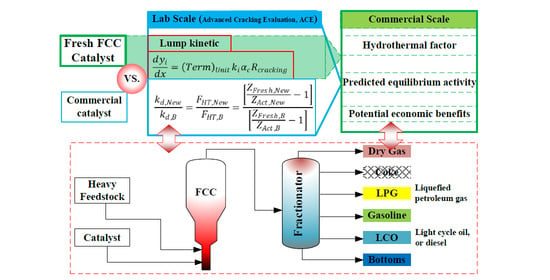
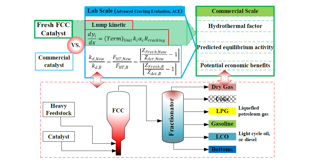
2.1. Simulated Industrial Evaluation Method

Due to the complex hydrodynamics and mixture, the lumping kinetic model has gained acceptability in description of an industrial FCC unit. For instance, the six lumped kinetic model has a feed, and five products, consisting of diesel, gasoline, liquefied petroleum gas (LPG), dry gas, and coke, adequately represent the product distribution [16,17,19]. If all products deem directly from the cracking of the feedstock oil, the reaction rate or the kinetic model equations can be expressed as fellow:
R i = k i α c R c r a c k i n g
d y i d x = ( T e r m ) U n i t k i α c R c r a c k i n g
where R i and R c r a c k i n g are reaction rates of each product and cracking,   y i are the weight fractions, k i are the overall rate constants, α c are catalyst deactivation coefficients. All of the units of variable are 1 except the k i of s−1, since the reaction rates are described by weight fractions.
Thus, the products can be represented approximately by linear relations of feedstock conversion at constant reaction temperature,
y i = S i Z c r a c k i n g
Z c r a c k i n g = C F e e d 1 C F e e d
where S i are the slope of linear relations, Z c r a c k i n g are referred as the equilibrium activity function and C F e e d is the weight percent conversion (%), which includes the all products except diesel (light cycle oil, LCO) and bottoms.
However, due the deactivation effect, the regeneration of the recycled catalyst and supplementation of the fresh catalyst were adopted to maintain certain catalyst activity and feedstock conversion. The equilibrium activity function has the relationship with these facts.
Z c r a c k i n g = D R R C D R R C + k d Z F r e s h
where Z F r e s h is the fresh activity function, k d is the overall deactivation coefficient, DRRC is the daily replacement rate of catalyst, representing the catalyst make-up rate at unit catalyst inventory per day. Since the main deactivation factors are hydrothermal effect and metals upon the catalyst, k d can be further refined by these two factors:
k d = F H T y H 2 O 0.1 F M C
where F H T and F M C   are the deactivation factors of hydrothermal effect and metal contaminant, respectively. The former factor F H T is a function of temperature and the water content ( y H 2 O ) in the regenerator bed flue gas, and is specifically indicated with 95% stream here. The latter factor, F M C , adjusts catalyst deactivation due to equilibrium catalyst metals content. Based on Equations (5) and (6), either higher values of F H T or F M C   would means fast deactivation, which would result in higher make up rates being required to maintain a given equilibrium catalyst activity.
Catalyst stabilities all tend to be similar at low regenerator temperatures, but can be substantially different at high temperatures. Thus, a series of temperatures have been introduced to describe the hydrothermal effect [9,18]. Then, for the similar metal deactivation of catalyst, the F H T at different temperature can be reformulated through Equations (5) and (6) as follows:
k d , T k d , T 0 = F H T , T F H T , T 0 = [ Z F r e s h Z A c t , T 1 ] [ Z F r e s h Z A c t , T 0 1 ]
Similarly, for the same FCC system at same temperature, different catalysts are supposed to have the analogous relationship for deactivation factors:
k d , N e w k d , B = F H T , N e w F H T , B = [ Z F r e s h , N e w Z A c t , N e w 1 ] [ Z F r e s h , B Z A c t , B 1 ]
Therefore, based on Equations (3) and (8), one may evaluate the relative performance of a fresh FCC catalyst comparing to a base catalyst in a given performance category. In other words, if there is a certain base catalyst with a complete set of hydrothermal deactivation data, such as equilibrium catalyst (E-Cat), one may use Equations (3)–(8) to rapidly assess a fresh FCC catalyst at the industrial level. Besides, these results could be further used to evaluate the DRRC, and the economic benefits of the fresh catalyst if the market information of raw materials and products is known.

2.2. Recommended Experimental and Device Requirements

To apply the hydrothermal deactivation for industrial evaluation, suitable laboratory tests for any catalyst should be available, and the following catalytic testing are recommended, both the fresh catalyst and the base catalyst. The fresh catalyst is treated with the recommended steaming conditions in Table 1, which were recommend by Petro-sim of KBC corporation [20,21]. However, the certain actual FCC process may deviate from the recommended activity, then the hydrothermal conditions are suggested to be modified for the actual E-Cat.
Moreover, these experimental data must have a high degree of precision of ±0.5 for conversion and mass balance so as to ensure the accuracy of the evaluation. In the work, we adopt the high throughput apparatus of Advanced Cracking Evaluation (ACE) to carry out the hydrothermal treatment (ACE HT-100) and catalysis test (ACE-Model R+ MM), which has good parallelism and precision to further industrial evaluation. Both apparatuses are licensed from Kayser Technology Inc. of Houston, Texas, USA.
The ACE-Model HT-100 is a pilot plant for hydrothermal (HT) deactivation of catalysts in lots as larger as 100 g. The catalyst (50~100 g) was calcined for 2 h at 800 °C and then added into the reactor. Deionized water was introduced into the reactor by high performance liquid chromatography (HPLC) pump, and the steam ratio was adjusted by adjusting the amount of fluidized nitrogen. The aging temperature is controlled by a six section furnace, and the temperature control accuracy is ±1 °C. The proportion of steam and aging temperature are determined according to the experimental scheme. The velocity for the steaming cycle is 6 cm/sec in the lower reactor section.
Cracking performance was tested in an ACE-Model R+ MM unit. The 9 g catalyst is added and the temperatures are 515 °C and 715 °C for reaction and regeneration, respectively. The catalyst to oil ratio (C/O = 5.0) was performed. Gaseous products are analyzed using an INFICON GC-3000 online chromatograph, according to the Universal Oil Products Company (UOP) method 539. Simulated distillation of liquid products are carried out using an Agilent 7890B chromatograph according to the SH/T 0558 procedure. Coke deposited on the catalyst was quantified with a SERVOMEX CO2 analyzer.

2.3. Catalysts to Be Evaluated

Several FCC catalysts were selected, screened, roasted, and compounded in a certain proportion for hydrothermal treatment and catalysis test, and then the forecasting or industry evaluation were carried out to analyze and verify the evaluation method. The selected catalysts are listed in Table 2, and the properties of heavy feed oil are listed in Table 3. These catalysts, except LHG catalyst, had been tested in FCC of heavy oil with certain advantage [22,23,24].

3. Results and Discussion

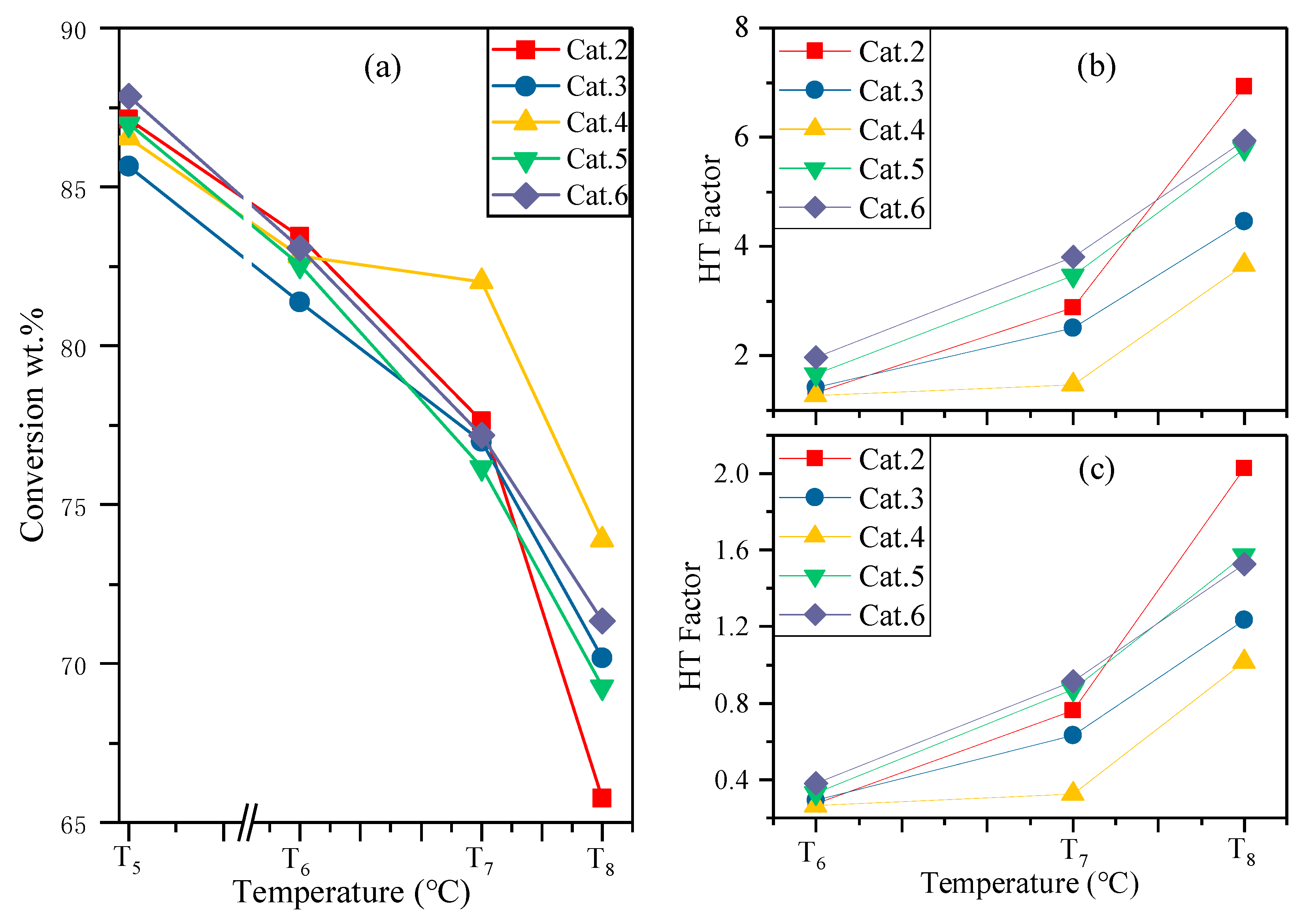
3.1. Modification for Hydrothermal Conditions

For each recommended hydrothermal condition, the selected catalysts were treated and then tested at the same reaction conditions through ACE-Model. Parallelism and accuracy test for the experimental equipment had shown that the results have a high degree of precision of ±0.5 for conversion and mass balance, which would ensure the accuracy of the evaluation.
The catalytic activities were compared with the reference activity under recommended conditions by Kayser Technology, Inc. [20,21]. As shown in Table 4, the activities of selected catalysts were much higher than the reference value for both Cat.1 and Cat.2, which indicates that the hydrothermal effects are mild within the current recommended conditions. The activity of moderate deactivation deviated from that of E-Cat. Actually, many FCC E-Cat have conversion, about 72~76% [9,11,17]. Therefore, it is necessary to modify the hydrothermal conditions and the “Reference conversion” or “Reference catalyst” to fit the conditions of commercial units.
Besides the temperature, the hydrothermal aging time also influenced the deactivation process [25], which presents the daily replacement rate of catalyst (DRRC). So, after repeated exploration of hydrothermal aging temperature and time, the moderate deactivation conditions were tested, and conversion performance was close to the value of 75.01% for E-Cat. Then, the new serial hydrothermal conditions were adjusted with the temperature difference on the basis of the recommended value with the new hydrothermal aging time. The product distributions of E-Cat and Cat.2 are compared in Figure 1, and the ACE run report is listed in Table 5.
The conversion decreased from 87.13% to 83.44%, 77.63, and, at last, to 65.75% for the fresh to mild, moderate, and severe deactivation. As shown in Figure 1, the fresh catalyst had the highest coking rate and yield of light component products due to the high activity, and the severe sample showed a large amount of uncracked bottoms but a similar yield of gasoline. While the moderate catalyst showed a higher yield of gasoline but a lower yield of LPG than that of E-Cat at the same level conversion. This difference may be due to the metal deactivation effect on the E-Cat [4,26]. Therefore, these results were consistent with the hydrothermal deactivation and would reflect the industrial catalytic process for further evaluation of the compounded FCC catalysts. Then, the Cat.2 was deemed as a “Reference catalyst” and the experimental results under the modified conditions were used to demonstrate the prediction of equilibrium activity and industrial evaluation in the following sections.

3.2. Predicted Equilibrium Activity

Based on Equations (3) and (4), the product yields were approximately proportional to the activity of FCC catalyst under the same reaction conditions. One may obtain different conversions by changing the ratio of catalyst to oil and then predict the product distribution for the equilibrium conversion. The predict yields for Cat.2 are shown in Figure 2. At the same conversion of E-Cat, the calculated yields showed similar distribution, but with lower yield of LPG and higher yield of gasoline, which is also due to the metal deactivation effect, since the metal upon the FCC catalyst would lead to the cracking and dehydrogenation reactions besides the deactivation effect [4,27].

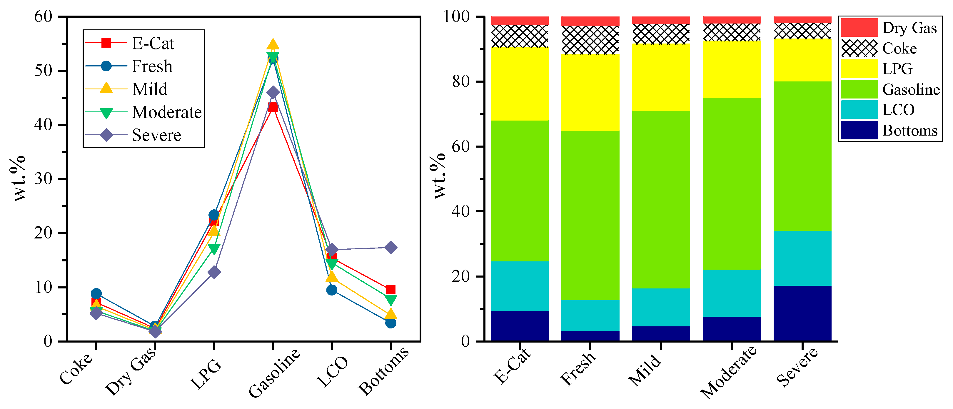
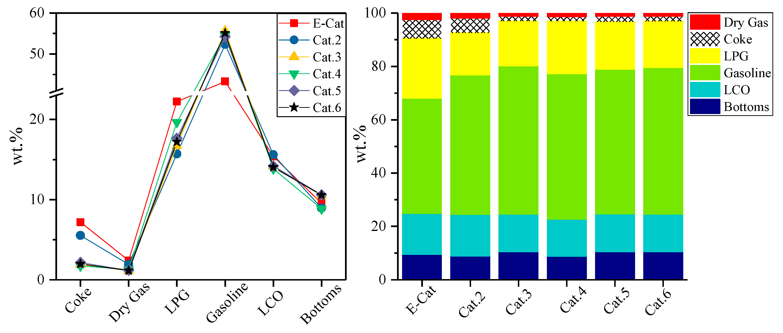
3.3. Industrial Evaluation for FCC Catalysts

The exploration of hydrothermal deactivation for Cat.1 and Cat.2 had given us a view for the approximate industrial evaluation to fresh FCC catalysts. The established series of hydrothermal treatments were further applied to the compounded FCC catalysts, their catalytic activities and HT factors are described in Figure 3.
The catalytic activity of the listed four compounded catalysts in Figure 3a decreased sharply under the current series conditions and the conversion of moderate deactivation remained above 75%, but that of severe deactivation was around 70%.
These data prove that the established series of hydrothermal treatments can include and reflect the cycle deactivation process of an industrial unit. Moreover, the HT factors based on the recommended base catalyst in Figure 3b had a larger range, although keeping linear characteristics, while the HT factors based on Cat.2 in Figure 3c showed similar trends to that of the recommended characteristics. This benchmarking treatment promoted us to compare the fresh catalyst with the base one, which would be further applied as an industrial evaluation of hydrothermal deactivation once the base one itself was a working industrial FCC catalyst. Thus, one can see that, compared with Cat.2, Cat.3, and Cat.4, had higher hydrothermal stability, but slightly lower activity, while Cat.5 and Cat.6 would have longer regeneration cycles or lower DRRC if maintaining the same conversion.
Accordingly, the predicted product distribution at equilibrium conversion for these four compounded catalysts are shown in Figure 4. All compounded catalysts exhibited similar product distributions to that of Cat.2, which is lower yield of LPG and dry gas but higher yield of gasoline than that of E-Cat. LDO-70 was tested as one of the catalysts for heavy oil conversion that can increase propylene yield and the octane number of gasoline [22]; LB-5 showed good resistance for abrasion and heavy metal [23]. By contrast with LDO-70, LPC-70 could improve the accessibility of heavy oil macromolecules to active centers, and then enhance the conversion of heavy oil and the selectivity of gasoline [24]. Therefore, when compared with Cat.2 as a base catalyst, Cat.3 had the highest yield of gasoline, but the lowest yield of dry gas, Cat.4 had the highest yield of LPG. Moreover, Cat.4 had a predicted conversion, about 77%, which deviates from linearity of 75%. This result indicates the Cat.4 has better hydrothermal stability and reactivity.

4. Conclusions

In this work, a convenient industrial evaluation method was proposed to assess the hydrothermal deactivation for fresh FCC catalyst. Based on the adjusted serial hydrothermal conditions, the hydrothermal stability and equilibrium yield of the fresh FCC catalyst could be assessed by comparing with certain equilibrium catalysts. The evaluation of the single or compounded catalyst showed different hydrothermal stabilities, but similar distribution, than that of E-Cat. Moreover, these results could be used to evaluate the DRRC, and then the economic benefits or potential for fresh FCC catalyst if the market information of raw materials and products is known, which will provide refiners industrial performances for further decisions.

Author Contributions

Conceptualization, Y.Y. and D.J.; methodology, Y.M., Y.L. and Y.S.; formal analysis, Y.S.; investigation, Y.M.; resources, Y.L.; data curation, Y.M. and Y.L.; writing—original draft preparation, Y.Y.; writing—review and editing, Y.M. and H.L.; visualization, Y.L.; supervision, D.J. All authors have read and agreed to the published version of the manuscript.

Funding

This research received no external funding.

Institutional Review Board Statement

Not applicable.

Informed Consent Statement

Not applicable.

Data Availability Statement

Not applicable.

Conflicts of Interest

The authors declare no conflict of interest.

References

  1. Huang, M.; Zheng, Y.; Li, S.; Xu, S. Enhancing Transient Event Trigger Real-Time Optimization for Fluid Catalytic Cracking Unit Operation with Varying Feedstock. Ind. Eng. Chem. Res. 2019, 58, 20340–20356. [Google Scholar] [CrossRef]
  2. Zhu, X.; Yu, M.; Cheng, M.; Wang, Y.; Zhang, H.; Wang, G.; Li, C. Conceptual Fluid Catalytic Cracking Process with the Additional Regenerated Catalyst Circulation Path for Gasoline Reprocessing and Upgrading with Minimum Loss. Energy Fuels 2020, 34, 235–244. [Google Scholar] [CrossRef]
  3. Chen, C.; Zhou, L.; Ji, X.; He, G.; Dai, Y.; Dang, Y. Adaptive Modeling Strategy Integrating Feature Selection and Random Forest for Fluid Catalytic Cracking Processes. Ind. Eng. Chem. Res. 2020, 59, 11265–11274. [Google Scholar] [CrossRef]
  4. Bai, P.; Etim, U.J.; Yan, Z.; Mintova, S.; Zhang, Z.; Zhong, Z.; Gao, X. Fluid catalytic cracking technology: Current status and recent discoveries on catalyst contamination. Catal. Rev. 2018, 61, 333–405. [Google Scholar] [CrossRef]
  5. Ma, W.; Liu, B.; Zhang, R.; Gu, T.; Ji, X.; Zhong, L.; Chen, G.; Ma, L.; Cheng, Z.; Li, X. Co-upgrading of raw bio-oil with kitchen waste oil through fluid catalytic cracking (FCC). Appl. Energy 2018, 217, 233–240. [Google Scholar] [CrossRef]
  6. Wang, C.; Tian, X.; Zhao, B.; Zhu, L.; Li, S. Experimental Study on Spent FCC Catalysts for the Catalytic Cracking Process of Waste Tires. Processes 2019, 7, 335. [Google Scholar] [CrossRef] [Green Version]
  7. Naik, D.V.; Karthik, V.; Kumar, V.; Prasad, B.; Garg, M.O. Kinetic modeling for catalytic cracking of pyrolysis oils with VGO in a FCC unit. Chem. Eng. Sci. 2017, 170, 790–798. [Google Scholar] [CrossRef]
  8. Usman, A.; Siddiqui, M.B.; Hussain, A.; Aitani, A.; Al-Khattaf, S. Catalytic cracking of crude oil to light olefins and naphtha: Experimental and kinetic modeling. Chem. Eng. Res. Des. 2017, 120, 121–137. [Google Scholar] [CrossRef]
  9. Sheng, Q.; Wang, G.; Liu, Y.; Husein, M.M.; Gao, C.; Gao, J. Pilot-scale evaluation of hydrotreating inferior coker gas oil prior to its fluid catalytic cracking. Fuel 2018, 226, 27–34. [Google Scholar] [CrossRef]
  10. Corma, A.; Sauvanaud, L.; Mathieu, Y.; Al-Bogami, S.; Bourane, A.; Al-Ghrami, M. Direct crude oil cracking for producing chemicals: Thermal cracking modeling. Fuel 2018, 211, 726–736. [Google Scholar] [CrossRef]
  11. Che, Y.; Yuan, M.; Qiao, Y.; Liu, Q.; Zhang, J.; Tian, Y. Fundamental study of hierarchical millisecond gas-phase catalytic cracking process for enhancing the production of light olefins from vacuum residue. Fuel 2019, 237, 1–9. [Google Scholar] [CrossRef]
  12. Etim, U.J.; Xu, B.; Peng, B.; Ullah, R.; Subhan, F.; Yan, Z. Role of nickel on vanadium poisoned FCC catalyst: A study of physiochemical properties. J. Energy Chem. 2016, 25, 667–676. [Google Scholar] [CrossRef]
  13. Jiang, H.; Livi, K.J.; Kundu, S.; Cheng, W.-C. Characterization of iron contamination on equilibrium fluid catalytic cracking catalyst particles. J. Catal. 2018, 361, 126–134. [Google Scholar] [CrossRef]
  14. Etim, U.J.; Xu, B.; Bai, P.; Ullah, R.; Subhan, F.; Yan, Z. Vanadium and nickel deposition on FCC catalyst: Influence of residual catalyst acidity on catalytic products. Microporous Mesoporous Mater. 2019, 273, 276–285. [Google Scholar] [CrossRef]
  15. Corma, A.; Sauvanaud, L. FCC testing at bench scale: New units, new processes, new feeds. Catal. Today 2013, 218–219, 107–114. [Google Scholar] [CrossRef]
  16. Sani, A.G.; Ebrahim, H.A.; Azarhoosh, M.J. 8-Lump kinetic model for fluid catalytic cracking with olefin detailed distribution study. Fuel 2018, 225, 322–335. [Google Scholar] [CrossRef]
  17. John, Y.M.; Mustafa, M.; Patel, R.; Mujtaba, I.M. Parameter estimation of a six-lump kinetic model of an industrial fluid catalytic cracking unit. Fuel 2019, 235, 1436–1454. [Google Scholar] [CrossRef] [Green Version]
  18. Occelli, M.L. Advances in Fluid Catalytic Cracking: Testing, Characterization, and Environmental Regulations; CRC Press: Boca Raton, FL, USA, 2010. [Google Scholar]
  19. Alvira, J.I.; Del Olmo, I.H.; Rodríguez, E.; Arandes, J.M.; Castano, P. A Data-Driven Reaction Network for the Fluid Catalytic Cracking of Waste Feeds. Processes 2018, 6, 243. [Google Scholar] [CrossRef] [Green Version]
  20. Available online: http://www.petro-sim.com.
  21. Available online: http://www.kaysertech.com.
  22. Liu, X.; Duan, H.; Zhao, Y.; Gao, G. Commercial application of LDO-70 efficient conversion catalyst for heavy oil. Pet. Refin. Chem. Ind. 2013, 44, 15–18. [Google Scholar]
  23. Hou, K.; Li, D.; Zhang, Y.; Wang, Z.; Tian, A.; Zhang, H. Effect of propylene-enhancing promoter on performance of catalyst LB-5 in heavy oil catalytic pyrolysis for light olefins. Appl. Chem. Ind. 2015, 44, 1710–1713. [Google Scholar]
  24. Wu, Z.; Xiong, X.; Ma, M.; Gao, W. Industrial application of FCC catalyst LPC-70 for improving gasoline yield. Pet. Refin. Chem. Ind. 2018, 49, 75–78. [Google Scholar]
  25. Fan, D.; Wang, J.; Yu, T.; Wang, J.; Hu, X.; Shen, M. Catalytic deactivation mechanism research over Cu/SAPO-34 catalysts for NH3-SCR (I): The impact of 950 °C hydrothermal aging time. Chem. Eng. Sci. 2018, 176, 285–293. [Google Scholar] [CrossRef]
  26. Wallenstein, D.; Farmer, D.; Knoell, J.; Fougret, C.; Brandt, S. Progress in the deactivation of metals contaminated FCC catalysts by a novel catalyst metallation method. Appl. Catal. A Gen. 2013, 462–463, 91–99. [Google Scholar] [CrossRef]
  27. Etim, U.J.; Xu, B.; Zhang, Z.; Zhong, Z.; Bai, P.; Qiao, K.; Yan, Z. Improved catalytic cracking performance of USY in the presence of metal contaminants by post-synthesis modification. Fuel 2016, 178, 243–252. [Google Scholar] [CrossRef]
Figure 1. Product distributions of equilibrium catalyst (E-Cat) and Cat.2 at new serial hydrothermal conditions.
Processes 09 00209 g001
Figure 2. Comparation of yields for E-Cat and prediction: Cal-75% represents the calculated yields based on the different ratio of catalyst to oil at the conversion of E-Cat.
Processes 09 00209 g002
Figure 3. Catalytic activity and hydrothermal (HT) factor for compounded FCC catalysts treated by the modified series hydrothermal conditions: (a) conversion, (b) HT factors based on the recommended base catalyst, (c) HT factors based on Cat.2.
Processes 09 00209 g003
Figure 4. Predicted product distribution at equilibrium conversion of 75% for four compounded catalysts.
Processes 09 00209 g004
Table 1. Steaming conditions for hydrothermal deactivation evaluation.
DescriptionRecommended ConditionsAssumed Regeneration TempModified Conditions
TempHoursTempHours
1Fresh activityT1 (705)6-T5H2
2Mild deactivationT2 (760)6660T6H2
3Moderate deactivationT3 (775)6705T7H2
4Severe deactivationT4 (795)6750T8H2
Note: (1) The steaming conditions are 1 atmosphere, 95% steam; the catalytic tests are carried out at the conditions of 515 °C, Weight hourly space velocity (WHSV) 25, and catalyst to oil of 5.0. (2) In current procedure, T5 = 735 °C, T6 = 790 °C, T7 = 805 °C, T8 = 815 °C, H2 = 24 h.
Table 2. Selected fluid catalytic cracking (FCC) catalysts and their compounded proportion.
No.CatalystsProportion
Cat.1LDO-70-
Cat.2YN-20, YN-E-Cat-
Cat.3LDO-70 + LB-54.25:1
Cat.4LPC-70 + LHG5:1
Cat.5LDO-70 + LB-56:1
Cat.6LDO-70 + LHG5:1
Note: Cat. is the abbreviations of catalyst; LDO, LB, LPC, LHG, YN are the catalyst label.
Table 3. Feed properties.
ProgramPropertyMetalContent/(μg/g)
Molecular Weight /(g/mol)374Ni9.57
Viscosity (100 °C)/(mm2/s)12.27V10.09
Density (70 °C)/(Kg/m3)867.3Na16
ω (Conradson Carbon Residue)/%4.17Ca18.11
Flash Point/°C204Fe10.22
ω (Paraffin)/%68.9Pb0.03
ω (Aromatics)/%21.7Cu0.87
ω (Gelatin)/%9.4
Table 4. Catalytic activity (wt. %) under different hydrothermal conditions.
DeactivationReference ConversionRecommended ConditionsModified Conditions
Cat.1ΔCat.2ΔCat.1Cat.2
Fresh76.7487.0110.2789.1412.4086.9887.13
Mild71.8584.1012.2585.4513.6082.5383.44
Moderate69.1383.0313.9084.4515.3276.1777.63
Severe67.179.0511.9581.5014.4069.2765.75
Note: Δ means the conversion difference between the activity and reference value.
Table 5. Catalytic activity (wt. %) for Cat.2 under Modified Conditions.
DescriptionE-CatYN-20
T5T6T7T7T8
Recovery, wt%101.0101.1101.0100.4100.7100.6
Conversion, wt%75.0887.1383.4477.6379.2865.75
Yields, wt%:
Coke7.208.836.485.675.775.18
Dry Gas2.402.822.141.901.911.83
Hydrogen0.310.050.050.060.060.06
Hydrogen Sulfide0.280.280.280.280.280.28
Methane0.690.970.720.620.640.60
Ethane0.470.680.520.480.460.47
Ethylene0.650.830.570.460.480.41
Propane1.161.941.100.770.810.53
Propylene7.695.985.625.075.373.98
n-Butane0.841.871.160.750.810.43
Isobutane3.697.355.133.453.851.82
C4 Olefins8.856.197.197.267.656.00
1-Butene1.661.391.561.471.561.15
Isobutylene3.041.311.802.222.282.13
c-2-Butene1.761.491.641.521.631.15
t-2-Butene2.351.972.162.012.151.52
Butadiene0.030.020.030.030.040.05
Gasoline43.2752.1654.6452.7753.1045.99
LCO15.399.5011.7214.5113.6816.92
Bottoms9.533.374.847.867.0417.33
TOTAL100.00100.00100.00100.00100.00100.00
Publisher’s Note: MDPI stays neutral with regard to jurisdictional claims in published maps and institutional affiliations.

