
Experimental Investigation on Turbulent Flow Deviation in a Gas-Particle Corner-Injected Flow


Abstract
:1. Introduction
2. Experimental Details
2.1. Experimental Setup
2.2. Measurement Duties
2.3. Image Processing
2.4. Uncertainty Analysis and Statistical Feasibility Analysis
3. Results and Discussions
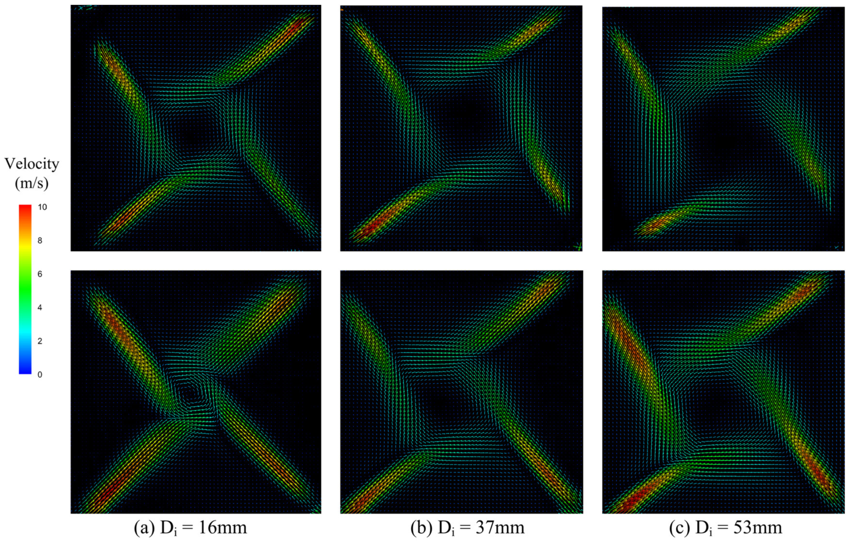
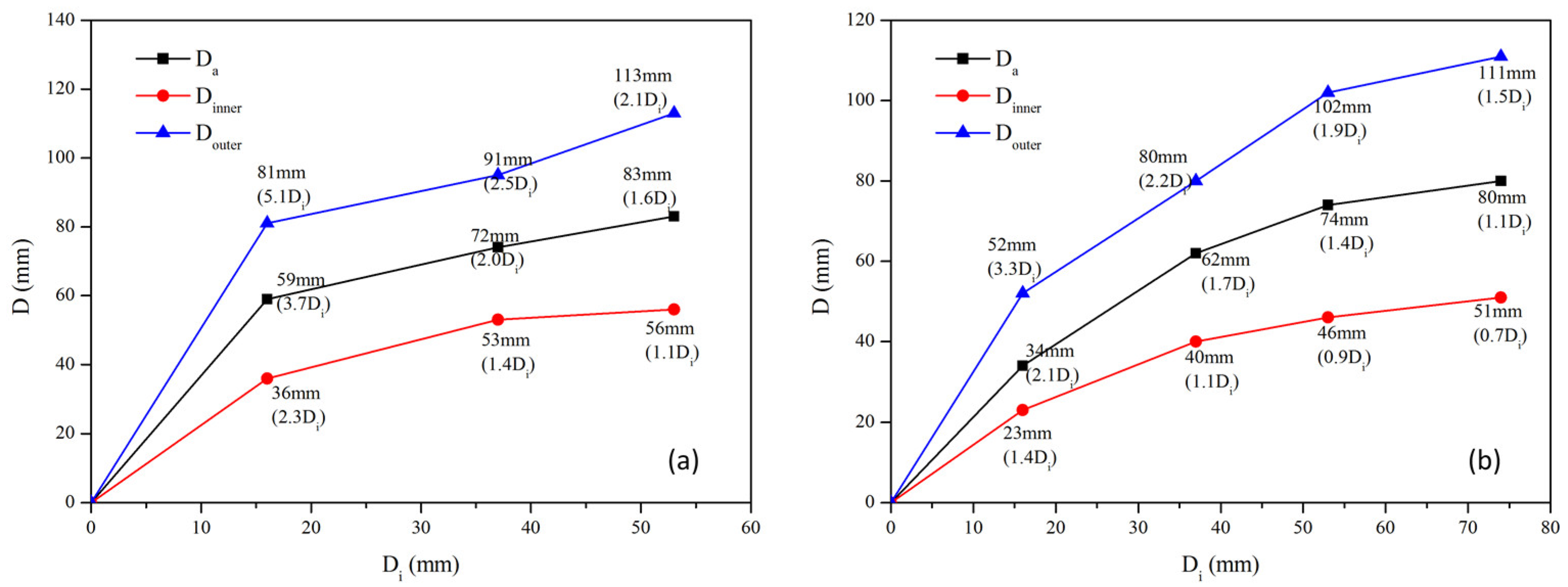
3.1. Corner-Injected Flow Characteristics
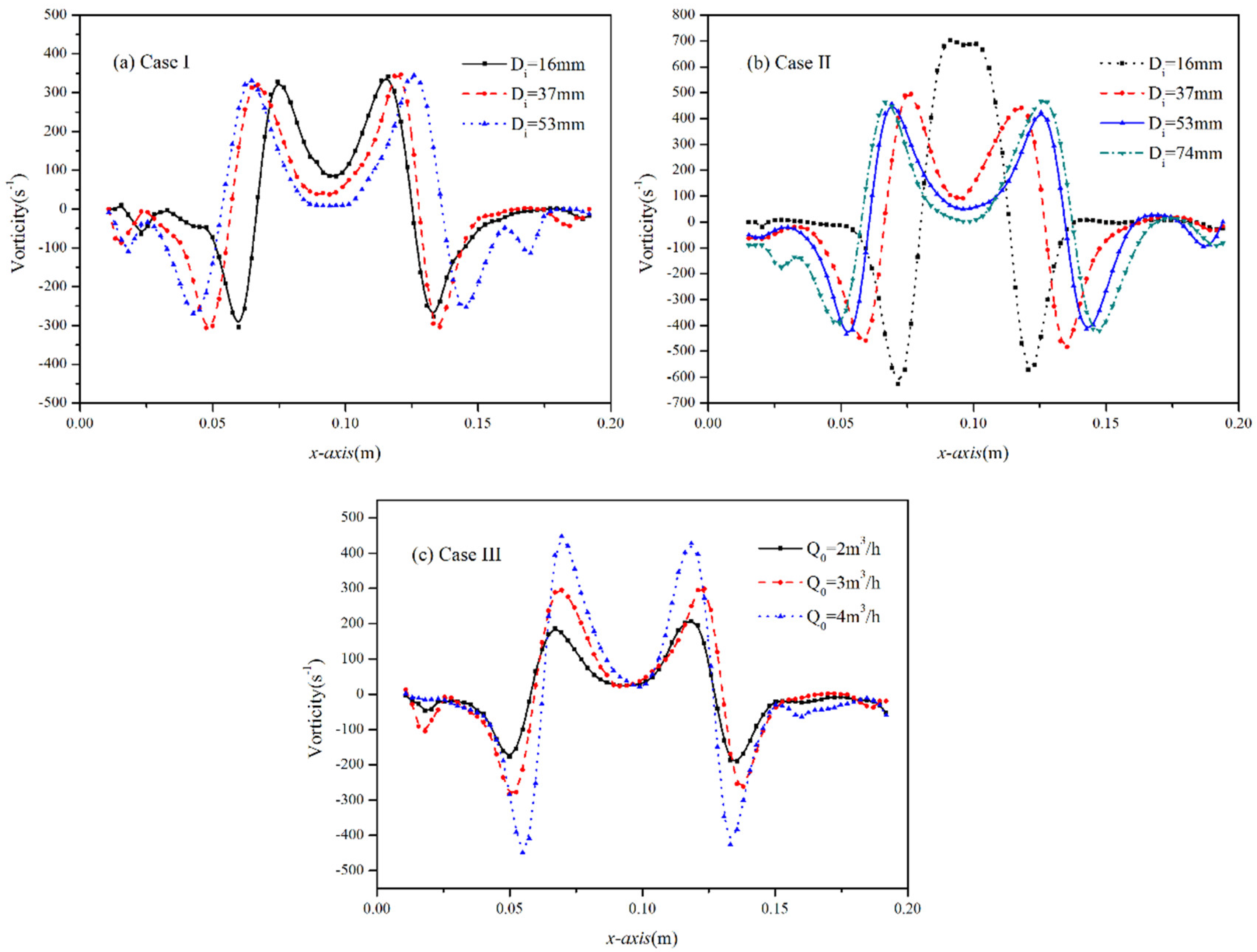
3.2. Vortex Evolution Characteristics
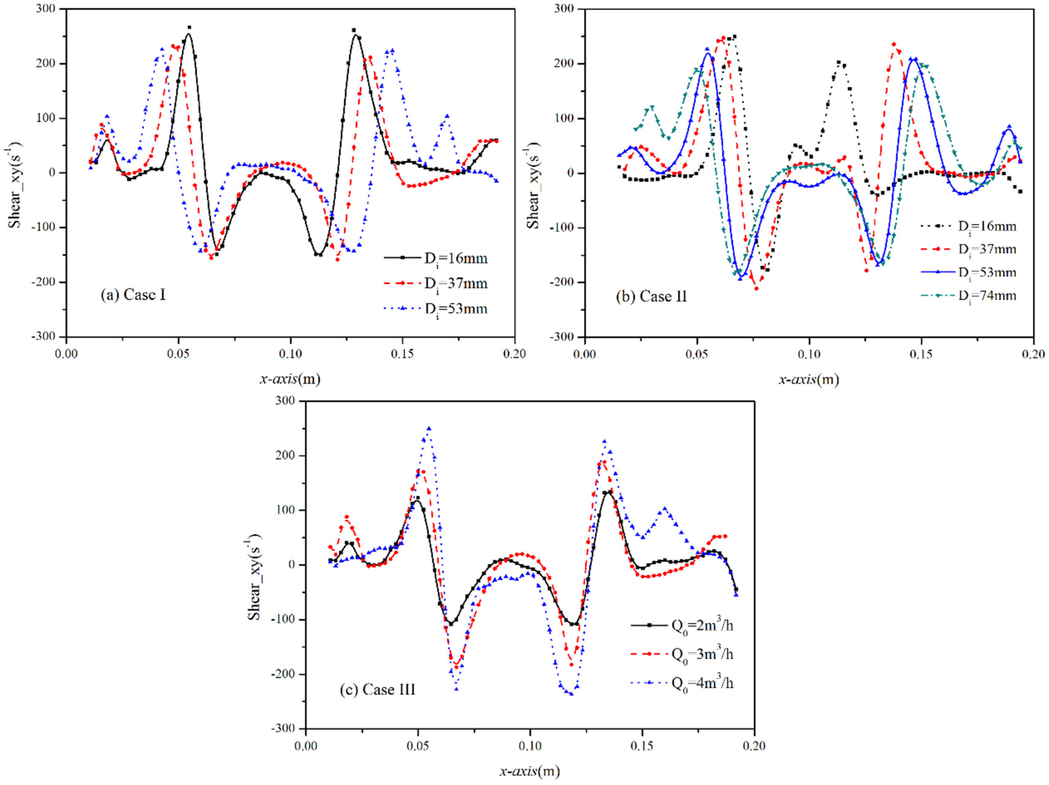
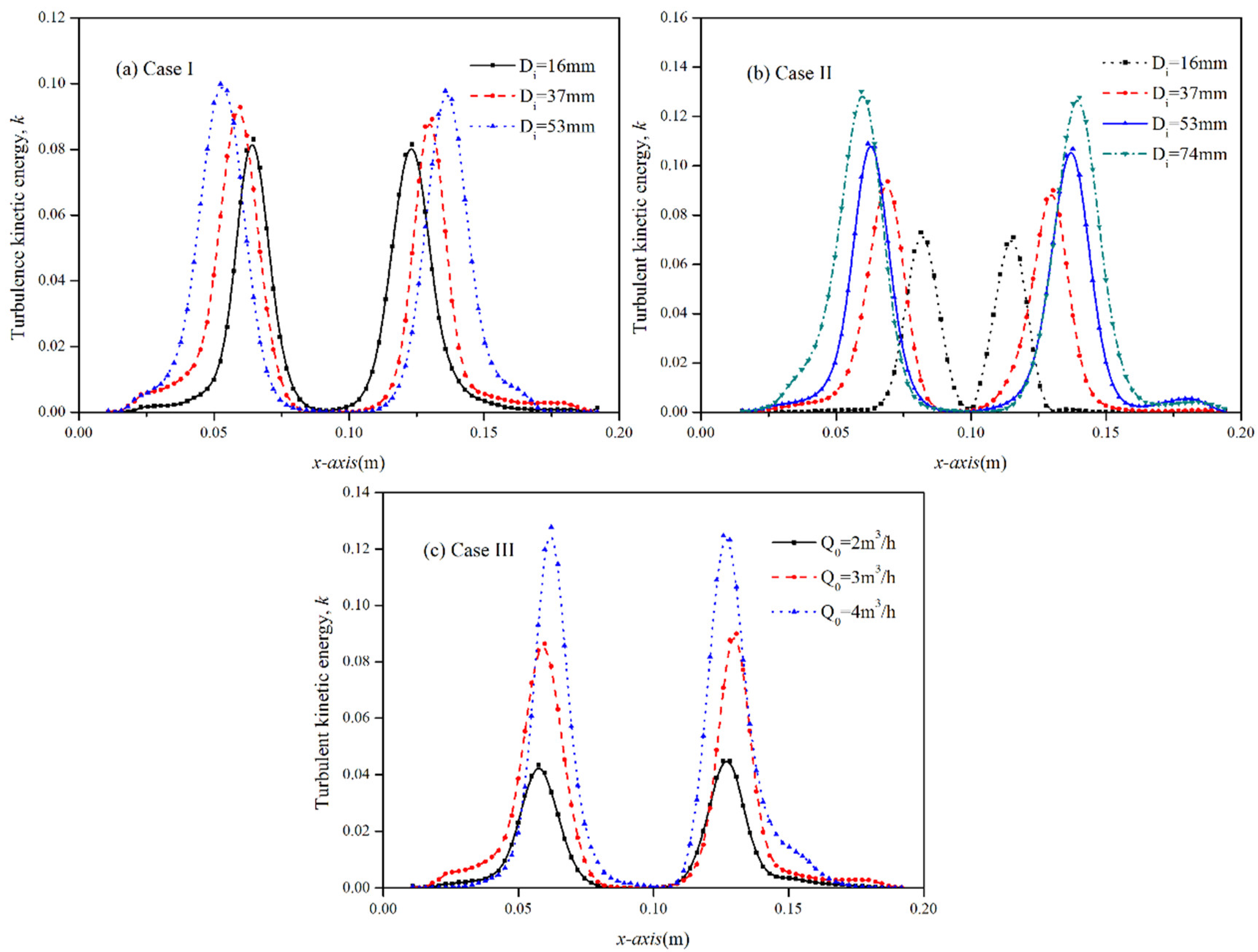
3.3. Turbulent Flow Development
4. Conclusions
- (1)
- The influences of the increasing ideal tangential circle on the turbulent jet deviation are shortened gradually, and the impinging rotation flow is obviously narrowed with the injection of the laden particles. The gas-particle corner-injected flow can obtain good rotation when the ideal tangential circle is 0.25 times the width of the impinging chamber.
- (2)
- The momentum decay of the corner-injected flow diminishes with the increasing ideal tangential circle and the decreasing initial gas velocity. The actual tangential circle is little affected by the initial gas velocity at an appropriate range.
- (3)
- The rotation strength of vortex is more affected by the injection of laden particles than the ideal tangential circle. On the contrary, the angular distortion of vortex attenuates gradually with the growing ideal tangential circle, but is little affected by the additive particles. Both the rotation and distortion increase when increasing the initial gas velocity.
- (4)
- The increasing initial gas mass flux plays a dominant role in the development of the corner-injected flow, secondly the increasing ideal tangential circle, and last the injection of particles.
Author Contributions
Funding
Institutional Review Board Statement
Informed Consent Statement
Data Availability Statement
Acknowledgments
Conflicts of Interest
Nomenclature
| Cs | Smagorinsky constant, dimensionless |
| dp | The diameter of particle, μm |
| D | The width and depth of impinging chamber, mm |
| Da | The diameter of actual tangential circle, mm |
| Di | The diameter of ideal tangential circle, mm |
| Din | The inside diameter of round tubes, mm |
| Dinner | The diameter of inner circle tangency to four inside-edges, mm |
| Douter | The diameter of outer circle tangency to four lateral-edges, mm |
| I | The turbulence intensity, dimensionless |
| L | The length of four tubes, mm |
| PIV | Particle Image Velocimetry |
| Q0 | The initial mass flux for gas, m3/h |
| Re | Reynolds number, dimensionless |
| Sij | The strain rate tensor, dimensionless |
| u | The measured instantaneous velocity in x direction, m/s |
| U0 | The initial gas velocity, m/s |
| The time-averaged gas velocity, m/s | |
| x, y, z | Three dimensions, dimensionless |
| v | The measured instantaneous velocity in y direction, m/s |
| w | The measured instantaneous velocity in z direction, m/s |
| Greek letters | |
| X | Spatial resolution of velocity vectors, mm |
| ε | Turbulence dissipation rate, m2/s3 |
| The linear deformation of vortex in x direction, 1/s | |
| The linear deformation of vortex in y direction, 1/s | |
| The angular distortion of vortex in xy plane, 1/s | |
| ηk | Kolmogorov length scale, m |
| κ | Turbulence kinetic energy, dimensionless |
| Λ | Integral length scale, m |
| Dynamic viscosity of the gas, Ps·s | |
| Gas kinematic viscosity, m/s | |
| The vorticity in z direction, 1/s | |
| Particle density, kg/m3 | |
| ρg | Gas density, kg/m3 |
| τSGS | Stress tensor, dimensionless |
| Subscripts | |
| g | Gas |
| p | Particle |
| SGS | Sub-grid scale |
| i, j | x, y directions |
References
- Choi, C.R.; Kim, C.N. Numerical investigation on the flow, combustion and NOx emission characteristics in a 500 MW tangentially fired pulverized-coal boiler. Fuel 2009, 88, 1720–1731. [Google Scholar] [CrossRef]
- Sun, W.; Zhong, W.; Yu, A.; Liu, L.; Qian, Y. Numerical investigation on the flow, combustion, and NOx emission characteristics in a 660 MWe tangential firing ultra-supercritical boiler. Adv. Mech. Eng. 2016, 8, 1687814016630729. [Google Scholar] [CrossRef] [Green Version]
- Li, S.; Xu, T.; Hui, S.; Zhou, Q.; Tan, H. Optimization of air staging in a 1 MW tangentially fired pulverized coal furnace. Fuel Process. Technol. 2009, 90, 99–106. [Google Scholar] [CrossRef] [Green Version]
- Chen, S.; He, B.; He, D.; Cao, Y.; Ding, G.; Liu, X.; Duan, Z.; Zhang, X.; Song, J.; Li, X. Numerical investigations on different tangential arrangements of burners for a 600 MW utility boiler. Energy 2017, 122, 287–300. [Google Scholar] [CrossRef]
- Zhou, H.; Mo, G.; Si, D.; Cen, K. Numerical Simulation of the NOx Emissions in a 1000 MW Tangentially Fired Pulverized-Coal Boiler: Influence of the Multi-group Arrangement of the Separated over Fire Air. Energy Fuels 2011, 25, 2004–2012. [Google Scholar] [CrossRef]
- Liu, Y.; Fan, W.; Li, Y. Numerical investigation of air-staged combustion emphasizing char gasification and gas temperature deviation in a large-scale, tangentially fired pulverized-coal boiler. Appl. Energy 2016, 177, 323–334. [Google Scholar] [CrossRef]
- Guo, J.; Liu, Z.; Wang, P.; Huang, X.; Li, J.; Xu, P.; Zheng, C. Numerical investigation on oxy-combustion characteristics of a 200 MW e tangentially fired boiler. Fuel 2015, 140, 660–668. [Google Scholar] [CrossRef]
- Zhang, X.; Zhou, J.; Sun, S.; Sun, R.; Qin, M. Numerical investigation of low NOx combustion strategies in tangentially-fired coal boilers. Fuel 2015, 142, 215–221. [Google Scholar] [CrossRef]
- Zhou, Y.; Xu, T.; Hui, S.; Zhang, M. Experimental and numerical study on the flow fields in upper furnace for large scale tangentially fired boilers. Appl. Therm. Eng. 2009, 29, 732–739. [Google Scholar] [CrossRef]
- Liu, Y.C.; Fan, W.D.; Wu, M.Z. Experimental and numerical studies on the gas velocity deviation in a 600MWe tangentially fired boiler. Appl. Therm. Eng. 2017, 110, 553–563. [Google Scholar] [CrossRef]
- He, B.; Diao, Y.; Xu, J.; Chen, C. Vorticity measurements in complex 3-D flow in tangentially-fired furnaces. Flow Meas. Instrum. 2002, 13, 173–181. [Google Scholar] [CrossRef]
- He, B.; Chen, M.; Liu, S.; Fan, L.; Xu, J.; Pan, W.P. Measured vorticity distributions in a model of tangentially fired furnace. Exp. Therm. Fluid Sci. 2005, 29, 537–554. [Google Scholar] [CrossRef]
- He, B.; Chen, M.; Yu, Q.; Liu, S.; Fan, L.; Sun, S.; Xu, J.; Pan, W.-P. Numerical study of the optimum counter-flow mode of air jets in a large utility furnace. Comput. Fluids 2004, 33, 1201–1223. [Google Scholar] [CrossRef]
- Li, J.; Wang, H.; Xiong, Y.; Jiang, G.; Liu, Z.; Zheng, C. Experimental investigation on turbulence modification in a dilute gas-particle axisymmetric opposed jets flow. Chem. Eng. J. 2016, 286, 76–90. [Google Scholar] [CrossRef]
- Mizeraczyk, J.; Kocik, M.; Dekowski, J.; Dors, M.; Podliński, J.; Ohkubo, T.; Kanazawa, S.; Kawasaki, T. Measurements of the velocity field of the flue gas flow in an electrostatic precipitator model using PIV method. J. Electrost. 2001, 51–52, 272–277. [Google Scholar] [CrossRef]
- Lindken, R.; Merzkirch, W. A novel PIV technique for measurements in multiphase flows and its application to two-phase bubbly flows. Exp. Fluids 2002, 33, 814–825. [Google Scholar] [CrossRef]
- Capone, A.; Romano, G.P.; Soldati, A. Experimental investigation on interactions among fluid and rod-like particles in a turbulent pipe jet by means of particle image velocimetry. Exp. Fluids 2005, 56, 1–15. [Google Scholar] [CrossRef]
- Lau, T.C.W.; Nathan, G.J. Influence of Stokes number on the velocity and concentration distributions in particle-laden jets. J. Fluid Mech. 2014, 757, 432–457. [Google Scholar] [CrossRef] [Green Version]
- Melling, A. Tracer particles and seeding for particle image velocimetry. Meas. Sci. Technol. 1997, 8, 1406–1416. [Google Scholar] [CrossRef]
- Liu, Z.; Zheng, Y.; Jia, L.; Zhang, Q. An experimental method of examining three-dimensional swirling flows in gas cyclones by 2D-PIV. Chem. Eng. J. 2007, 133, 247–256. [Google Scholar] [CrossRef]
- Sun, W.; Zhong, W.; Yu, A. Gas-particle turbulent flow of foursquare tangential jets in a simplified pulverized-coal firing boiler. Adv. Powder Technol. 2018, 29, 1463–1473. [Google Scholar] [CrossRef]
- Li, J.; Wang, H.; Liu, Z.; Chen, S.; Zheng, C. An experimental study on turbulence modification in the near-wall boundary layer of a dilute gas-particle channel flow. Exp. Fluids 2012, 53, 1385–1403. [Google Scholar] [CrossRef]
- Raffel, M.; Willert, C.E.; Kompenhans, J. Particle Image Velocimetry: A Practical Guide; Springer Science & Business Media: Berlin/Heidelberg, Germany, 2007. [Google Scholar]
- Scarano, F.; Riethmuller, M.L. Advances in iterative multigrid PIV image processing. Exp. Fluids 2000, 29, S051–S060. [Google Scholar] [CrossRef]
- Sheng, J.; Meng, H.; Fox, R.O. A large eddy PIV method for turbulence dissipation rate estimation. Chem. Eng. Sci. 2000, 55, 4423–4434. [Google Scholar] [CrossRef]
- Sheikholeslami, M.; Jafaryar, M.; Li, Z. Nanofluid turbulent convective flow in a circular duct with helical turbulators considering CuO nanoparticles. Int. J. Heat Mass Transf. 2018, 124, 980–989. [Google Scholar] [CrossRef]


| Apparatus | Parameters | Typical Value |
|---|---|---|
| Impinging chamber | Height (mm) | 1000 |
| Width (mm) | 200 | |
| Depth (mm) | 200 | |
| Injection tubes | Injected diameter (mm) | 10 |
| Length (mm) | 1000 | |
| Gas parameters | Gas temperature (°C) | 15 |
| Gas pressure (MPa) | 0.1 | |
| Gas density (kg/m3) | 1.22 | |
| Aerosol generator | Gas tracer diameter (μm) | 0.5 |
| Quantel EverGreen pulse | Time interval of Pulse 1 and 2 (μs) | 100 |
| Laser lasting time (nsec) | 5 | |
| Light sheet thickness (mm) | 0.5 | |
| Wavelength (nm) | 532 | |
| ILA CMOS Camera | Resolution (pixel) | 2560 × 2160 |
| Frame rate (Hz) | 4 | |
| Prime lens (mm) | 50 | |
| Aperture (f) | 1.8 | |
| ILA Synchronizer | - | - |
| Image collector | Image number | 100 |
| Case | Di (mm) | Q0 (m3/h) | U0 (m/s) | dp (μm) | Tracer |
|---|---|---|---|---|---|
| I-1 | 16 | 3 | 8.7 | - | Oil mist |
| I-2 | 37 | 3 | 8.7 | - | Oil mist |
| I-3 | 53 | 3 | 8.7 | - | Oil mist |
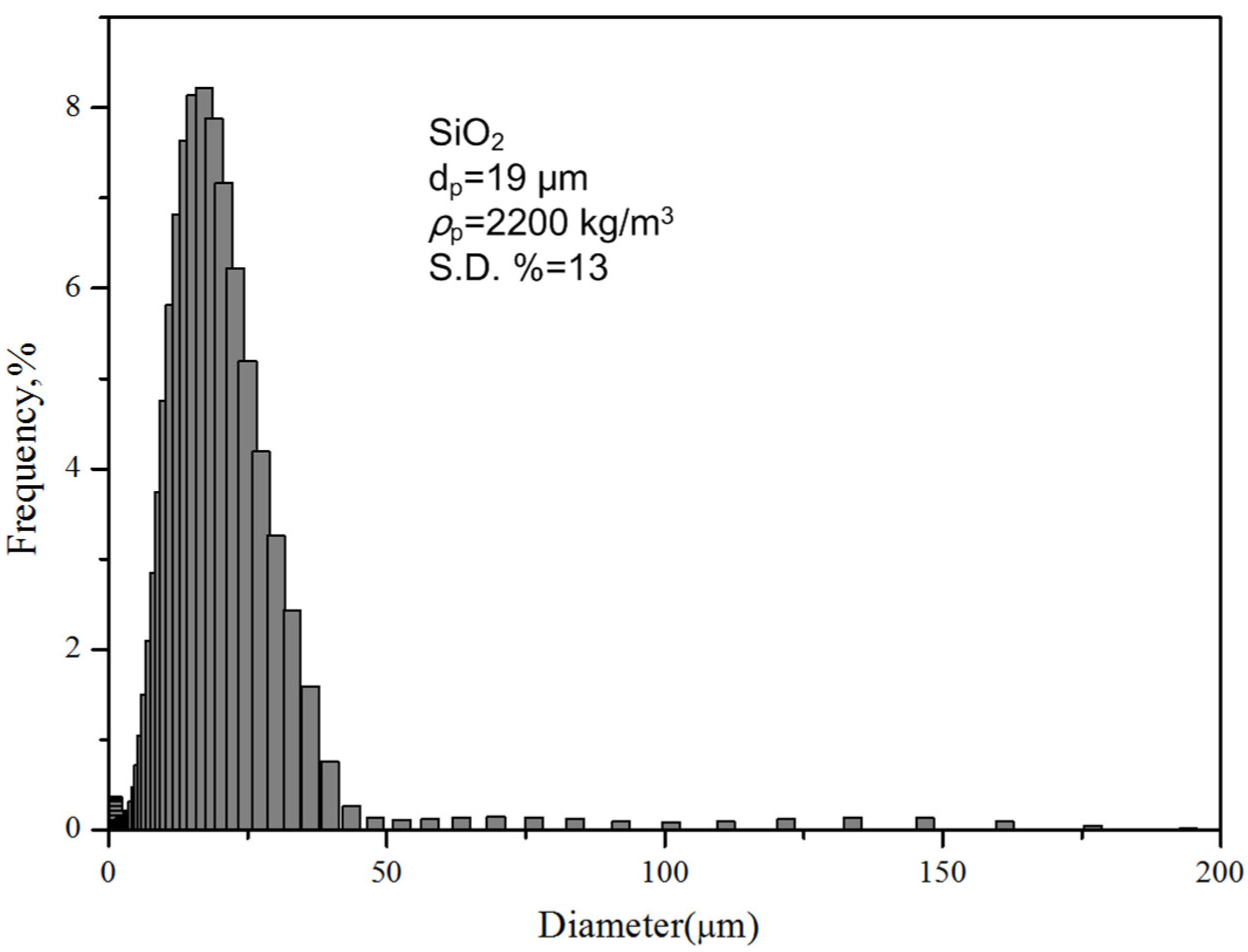
| II-1 | 16 | 3 | 8.7 | 19 | 99.9% SiO2 |
| II-2 | 37 | 3 | 8.7 | 19 | 99.9% SiO2 |
| II-3 | 53 | 3 | 8.7 | 19 | 99.9% SiO2 |
| II-4 | 74 | 3 | 8.7 | 19 | 99.9% SiO2 |
| III-1 | 37 | 2 | 5.8 | - | Oil mist |
| III-2 | 37 | 3 | 8.7 | - | Oil mist |
| III-3 | 37 | 4 | 11.6 | - | Oil mist |
Publisher’s Note: MDPI stays neutral with regard to jurisdictional claims in published maps and institutional affiliations. |
© 2021 by the authors. Licensee MDPI, Basel, Switzerland. This article is an open access article distributed under the terms and conditions of the Creative Commons Attribution (CC BY) license (https://creativecommons.org/licenses/by/4.0/).
Share and Cite
Sun, W.; Zhong, W.; Zhang, J. Experimental Investigation on Turbulent Flow Deviation in a Gas-Particle Corner-Injected Flow. Processes 2021, 9, 2202. https://doi.org/10.3390/pr9122202
Sun W, Zhong W, Zhang J. Experimental Investigation on Turbulent Flow Deviation in a Gas-Particle Corner-Injected Flow. Processes. 2021; 9(12):2202. https://doi.org/10.3390/pr9122202
Chicago/Turabian StyleSun, Wenjing, Wenqi Zhong, and Jingzhou Zhang. 2021. "Experimental Investigation on Turbulent Flow Deviation in a Gas-Particle Corner-Injected Flow" Processes 9, no. 12: 2202. https://doi.org/10.3390/pr9122202
APA StyleSun, W., Zhong, W., & Zhang, J. (2021). Experimental Investigation on Turbulent Flow Deviation in a Gas-Particle Corner-Injected Flow. Processes, 9(12), 2202. https://doi.org/10.3390/pr9122202