1. Introduction
One of the major issues in modern Europe is the management of waste produced by various human activities. For the past decade, the use of renewable energy has been growing at a rate of 2.7% per year, 50% faster than the 1.8% annual growth of the overall energy market over the same period. Amongst the entire waste, about 45% is formed by biomass which can be utilised for further reprocessing, e.g., production of hydrogen rich gas, methanol or syngas, or other modern technology for production of combustible gas.
New and advanced high temperature gasification technology (HIGHTEMPBIOMASS) based on slugging-gasifier, ceramic honeycomb regenerator and innovative hybrid adsorption membranes could offer numerous advantages for the thermal conversion of biomass and waste, among others, for production of hydrogen rich gas. Most biomass and waste pose significant challenges due to their significant variation in composition both spatially and temporally. Furthermore, the average calorific value associated with the biomass and waste is not uniform. Any technology used for the biomass and waste must be insensitive to any variations in their composition. Efficient conversion of biomass and waste into hydrogen rich gas of high heating value offers such advantages. The characteristic variation in the biomass and waste stream can be much reduced by converting into a fuel stream. An advanced gasification system, to be developed within the proposed project, utilises high-temperature preheated air/steam to convert biomass and waste into synthetic fuel gas and value-added by-products. Also, the production of H2 from gasification product can be enhanced with the use of H2 hybrid adsorption membranes.
Thermochemical processing of conventional renewable resources, solid fuels, biomass, municipal and hazardous waste in general, using high temperature gasification gained importance after the introduction of strict environmental regulations on the emission of criteria pollutants, which include particulate matter (PM), acid gases (HCl, HF and SO2), nitrogen oxides (NOx) and carbon monoxide (CO). Along with the criteria pollutants, thermal conversion systems also emit small amounts of trace organics and trace metals classified as toxic pollutants. Special interest in non-criteria pollutants (acid gases, trace metals, organics pollutants) surfaced after their risk assessment findings regarding human life. In addition, the dioxins and furans have become the focus of worldwide concern because of their carcinogenic properties.
The present project application aims at the development of a very attractive and efficient technology of gasification of biomass in the presence of air and steam. The partners joined in the project consortium developed a technology that may become a breakthrough technology in the management of biomass and municipal solid waste. The process of project realisation will be divided into some well-defined activities ranging from collection of a pan-European data bank on biomass available in particular countries, through the fundamental research and development of a pilot plant, to the demonstration site in a mid-sized town.
2. State-of-the-Art Gasification of Biomass and Waste
In recent years, pollution of the natural environment with waste generated during the conversion of primary energy has caused understandable concern among the scientific, governmental and international communities. Utilization of biomass and municipal waste can be carried out through the use of various types of technologies, among which high-temperature gasification as part of the HTAG-MEET technological cycle is classified as the most effective and environmentally friendly, and the surplus energy occurring during utilization can be used for various industrial purposes, [
1,
2,
3,
4,
5,
6,
7,
8]. This concept is based on the gasification of biomass and municipal waste with the use of air, a mixture of air and water vapor at a temperature exceeding 1000 °C. The produced gas, known as syngas (synthetic gas), is cooled in a waste heat boiler and then purified using traditional methods. Part of the syngas obtained in this way can be used for high-temperature, regenerative heating of air or air/steam mixtures, and the rest of the gas is used for energy purposes (e.g., combustion in a boiler, furnace or gas turbine) as well as hydrogen or methanol production. The thermal technology of biomass and municipal waste processing consists of three basic processes: pyrolysis, gasification and combustion. The most commonly used biomass and municipal waste utilization processes are their incineration in classic, fluid or rotary incineration plants or even cofiring biomass and fossil fuels [
9,
10,
11,
12,
13]. Electric, microwave or plasma heating systems are also used. Thermal utilization has an advantage over the other technologies because as a result of its use, biomass and municipal waste are completely decomposed into two fractions: gaseous and solid. The latter, in the form of a trail, can be used as a building material. In the HTAG-MEET technological cycle, biomass and municipal waste are converted, resulting in obtaining high-calorific gas fuel and solid waste that are harmless to the natural environment. The obtained synthetic gas (syngas) is partly used for the regenerative heating of air or air and water vapor, and the rest of the gas is used for the production of electricity and heat (cogeneration). The entire HTAG-MEET installation can be used even on a small scale with high economic benefits. The proposed research topic was aimed at examining the possibility of using the thermal utilization of biomass and municipal waste through their high-temperature decomposition in the presence of air, a mixture of air and steam [
14,
15,
16,
17,
18,
19,
20,
21,
22,
23,
24]. It was planned that the thermal decomposition of biomass and municipal waste would take place in a flow reactor with a filling in the form of ceramic balls or “pebble bed” bars, intercepting all kinds of solid particles and stabilizing the conversion process (reducing the amount of dioxin emissions, nitrogen oxides, etc.). The Institute of Energy (previously Department of Heat Technology) of the Gdańsk University of Technology has been cooperating for many years with the leading research centers from the EU, Japan and the USA on the issues of physical and numerical modeling of combustion and gasification processes. A bilateral cooperation agreement with the Royal Institute of Technology (KTH), Stockholm, Sweden serves as an example of such a cooperation. Utilization of the knowledge of foreign partners will obviously verify and supplement the proposed research program. Relevant information on equipment and technological processes for the utilization of biomass and municipal waste can also be obtained in the work of Gupta et al. [
3] and Blasiak et al. [
5,
8] and conference materials published by the European Union under FP6 and FP7.
3. High Temperature Air/Steam Gasification
Gasification of biomass and municipal wastes is the conversion of organic carbon and hydrogen compounds into a gas fuel containing mainly hydrogen H2 and carbon monoxide CO with a small amount of carbon dioxide CO2, water H2O, methane CH4, light hydrocarbons CmHn and nitrogen N2. The gasification process is assessed depending on the following parameters:
- -
equivalence ratio (ER = 1/λ);
- -
gasification temperature and heating rate;
- -
type of gasifying agent;
- -
pressure;
- -
properties of the feedstock, catalysts or process activating additives.
The gasification process itself is usually carried out at temperatures ranging from 500 to 1400 °C and at low (atmospheric) or elevated pressures. The oxidant can typically be air, water vapor, carbon dioxide, pure oxygen, or a mixture of these gases. Gasification with air or a mixture of air and water vapor produces a gaseous fuel with a high nitrogen content and LHV combustion heat of 4 to 6 MJ/m
3. During gasification based on pure oxygen or steam, a gas is obtained with a correspondingly high content of hydrogen and carbon monoxide and a much higher heat of combustion with a value of 12 to 18 MJ/m
3. The use of hydrogen or hydrocarbon compounds as the gasifying agent can lead to the production of gas with heat of combustion reaching the value of about 40 MJ/m
3. Gaseous fuels obtained as a result of gasification are used for direct combustion and production of heat and electricity, as a fuel for driving internal combustion engines or as an intermediate for the production of chemicals, hydrogen, methane or methanol. As a result of gasification, gaseous products are obtained, especially a mixture of such gases as: H
2, CO, CO
2, CH
4 and N
2, accompanied by tar compounds and solid residues with a high content of quartz compounds, heavy metals or sulfur. Thermal processing of biomass and municipal waste consists of the pyrolysis and gasification process. The pyrolysis process replaces the endothermic decomposition of the feed to volatile fractions (75–90%) in the form of gas or liquid hydrocarbons. The remainder, which contains a large amount of carbon, is called coke breeze (char or charcoal). Volatile hydrocarbons and coke breeze are converted to fuel gas in another stage called gasification. In the case of gasification processes, the following chemical reactions play a major role [
7]:
exothermic reactions:
combustion
partial oxidation
Methanation [
6]
endothermic reactions (Carrasse reactions) [6]:Bouduard reactionEquation (7) is called the tar steam reforming reaction [CmHn + nH2O ↔ (n + ½m) H2 + CO] and it determines the amount of formed hydrogen H2 and carbon monoxide CO in the gas fuel.
The formation of hydrogen during gasification with steam is controlled by the following reactions:
Dry tar reforming also takes place during the gasification process and it can be described by the following reactions:
Other chemical reactions besides the Bouduard reaction where CO
2 can be used as the gasifying agent are as follows:
When analyzing the gasification of biomass, municipal waste or hydrocarbon fuels from the point of view of chemical reactions, it is extremely difficult to present an unambiguous and complete mechanism of these reactions. Therefore, in mathematical modeling of gasification of even simple hydrocarbon compounds, all possible elementary reactions, the number of which can reach several hundred positions, are usually taken into account. Steam gasification produces a gas that is mostly free of nitrogen N2 and has a hydrogen content exceeding 50%. The use of appropriate catalysts can positively affect the efficiency of the reaction between steam and coke breeze and increase the tar content in the gas. Gasification with carbon dioxide CO2 as a gasification medium is a promising process due to the presence of this chemical in the reducing atmosphere. Tar reduction is also enhanced by dry reforming of the CO2 reaction, which is also a product of gasification.
The main objective of the study was an examination of the possibility of using the thermal utilization of biomass and municipal wastes through their high-temperature decomposition in the presence of air, a mixture of air and steam.
4. Experimental Set-Up
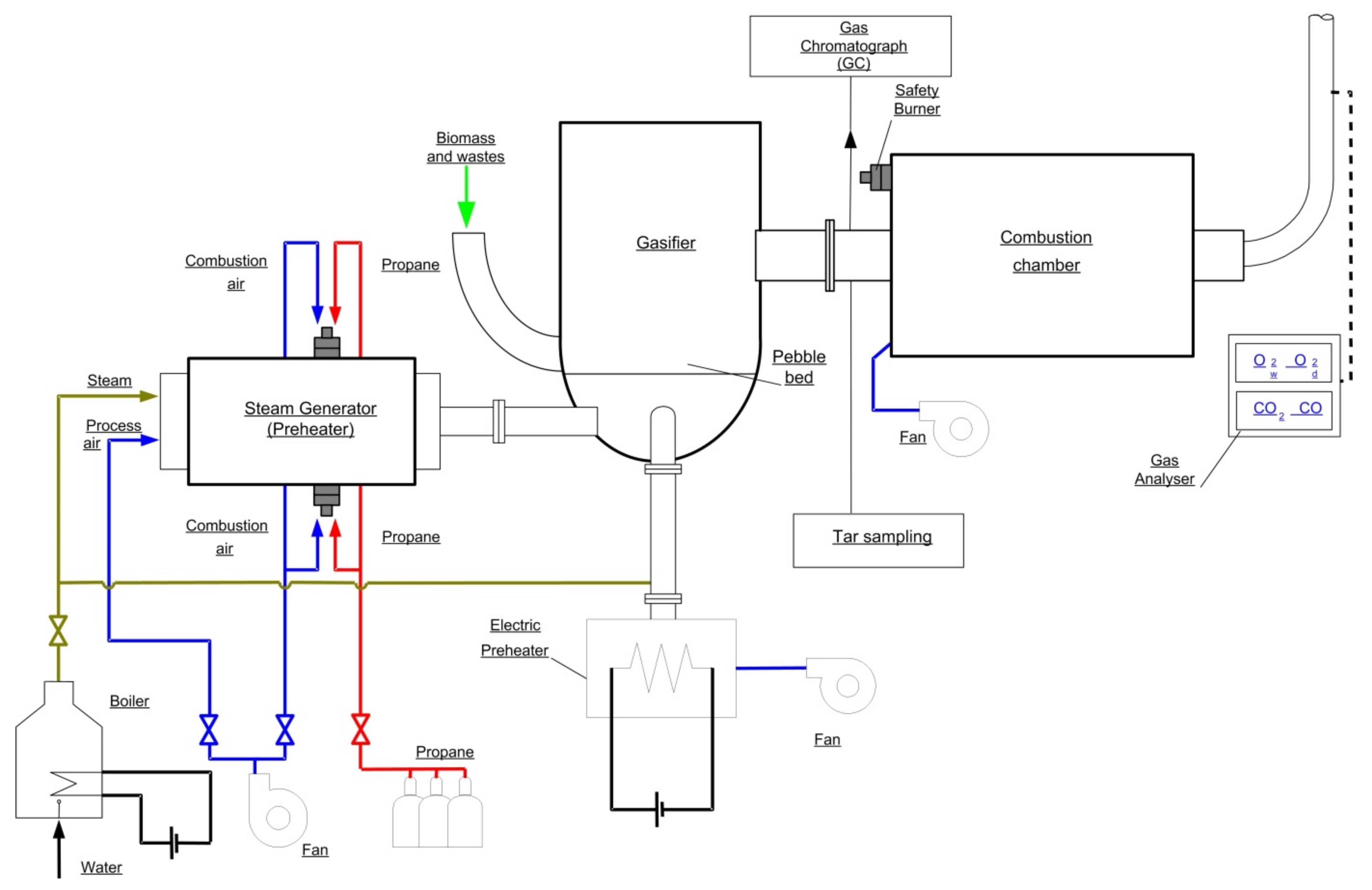
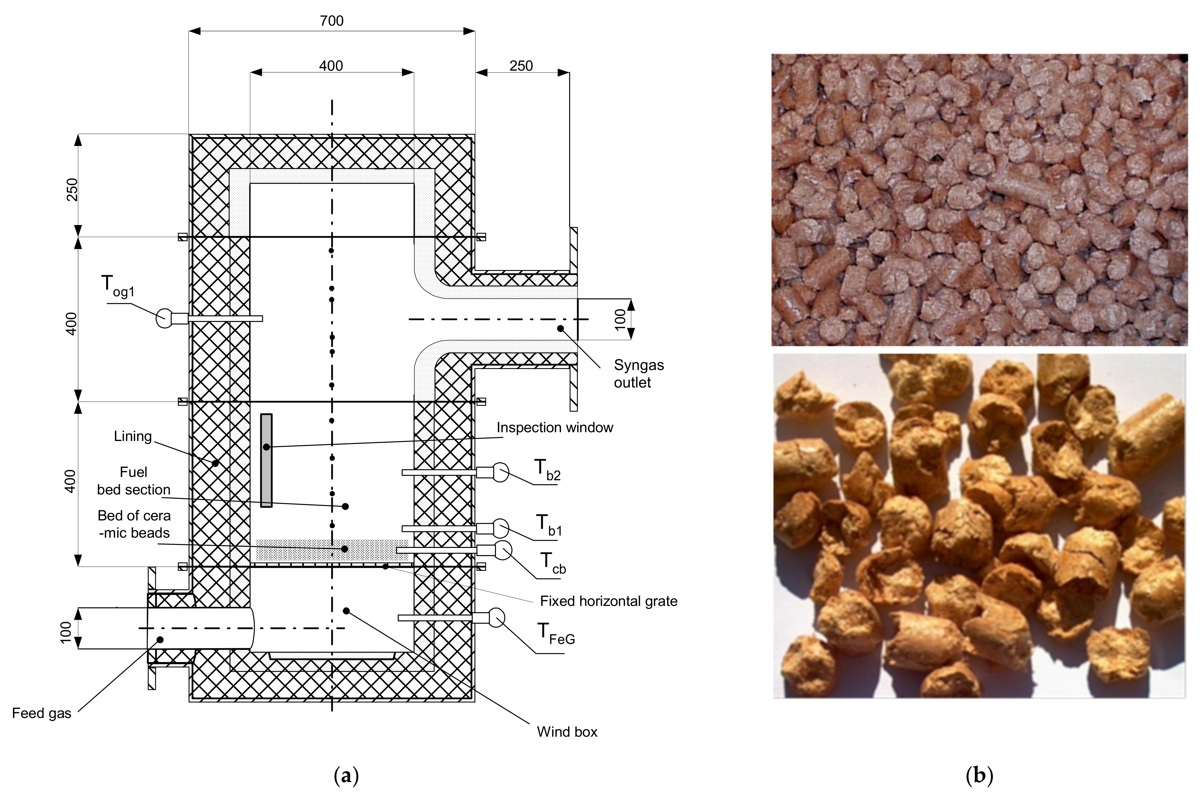
The batch reactor is equipped with a grate in the form of pebble bed type ceramic rods, it has the shape of a cylinder with the diameter of 400 mm and height of 1800 mm. It consists of three parts: a system of inspection windows, a section with a fixed bed (fixed grate) and a third element where the final gas reactions occur before exiting the gasifier (
Figure 1 and
Figure 2). Additionally, a secondary combustion chamber, or afterburner, for the gaseous fuel produced in the reactor is located directly below the gasifier. The afterburner is equipped with one inlet for gaseous fuel flowing out of the gasifier and one outlet for removing the exhaust gases generated in the combustion process. In addition, the afterburner is equipped with a pilot burner and a system of additional air nozzles. The purpose of these elements is to heat up the entire combustion chamber in the initial stage of the experiment to ensure complete and total combustion of the gaseous fuel supplied from the gasifier. The afterburner exhaust duct is equipped with 8 nozzles that are activated automatically to supply cold water to cool the hot exhaust gases flowing into the atmosphere. The exhaust fan located at the outlet of the afterburner covers the pressure losses occurring during the experiments and, at the same time, allows the pressure inside the gasifier to be controlled. The oxidant supply system includes an air fan that supplies air to the heaters and the reactor. Two systems were used to heat the feed gas: the electrical system and the air superheating system. In all experimental cases, the air supply to the gasifier was carried out by means of fans and automatic control in order to maintain the operating pressure at the outlet of the reactor. The electric heater enables the air to be heated in the lower temperature range, up to 600 °C, and is the first air supply system. The air superheater (increases the enthalpy of the reactants) has been designed in such a way that it enables overheating of air, water vapor or a mixture of air and water vapor in a higher temperature range, reaching 1300 °C [
19,
20]. The power supply system equipped with a high-temperature superheater is called the second main power supply. Two other air systems are the combustion chamber supply system (afterburner) and the safety burner supply system.
The last element of the pilot installation is an electric steam generator used to produce superheated steam at the temperature of 180 °C and pressure of 2.5 bar. The steam generator is equipped with a water preparation system. The measuring instruments include:
- -
thermocouples for temperature measurement s type with accuracy ±2.5 °C (Czaki Co., Raszyn-Rybie, Poland);
- -
Agilent Technologies Quad micro 490-Pro gas chromatograph (GC) consisting of four independently controlled modules for measuring the gaseous fuel composition with the accuracy of 2–10 ppm (Agilent Technologies Denmark ApS, Denmark);
- -
a set of flow meters and pressure regulators of Bronkhorst (Bronkhorst High-Tech B.V., The Netherlands) to control the flows of air and water vapor;
- -
tar sampling system.
The data acquisition system consists of a Keithley measurement set in the form of type 2701 Multi-meter. It is equipped with two type 7708 multiplexers. Each multiplexer has 40 channels, each of which can measure voltage, resistance or current. Thanks to this, the multiplexer can be easily connected with thermocouples, pressure sensors and also with the output signal coming from the gas analyzer or the system of flow meters. In addition, the measuring set has a TCP/IP network connection with an individual IP address.
The following gas components of the fuel gas are measured: hydrogen (H2), carbon monoxide (CO), carbon dioxide (CO2), nitrogen (N2), oxygen (O2), methane (CH4) and higher hydrocarbons (CmHn). The composition of fuel gas was determined from gas samples taken at the gasifier outlet. All measurements will be performed using a sampling frequency of one sample per 115 s. The run time of 115 s will consist of 15 s sampling time and 100 s analysis time.
5. Experimental (Batch Type Gasification) Results and Fuel Gas Composition
The main goal of this experiment was to determine the effect of the feed gas composition and its temperature on the produced amount of gas fuel (syngas), its composition and calorific value LHV and HHV respectively. Higher Heating Value (HHV), also known as the gross calorific value or gross energy, refers to the heat released by the complete combustion of fuel, assuming that the water originally present in the fuel and any generated water are present in a condensed state. Lower Heating Value (LHV), also known as the net heating value, assumes that the water is present in a vapor state at the end of combustion and is determined by subtracting the latent heat of water vaporization from the HHV [
11,
12] Reacting fixed bed temperature (T
b1), the feed gas temperature (T
FeG), the ceramic beads temperature (T
cb) and temperature of the fuel gas (T
og1) were also measured in characteristic areas of the reactor. During the whole process, the measurement of gaseous fuel components such as: H
2, CO, CO
2, N
2, O
2, CH
4 and light hydrocarbons (C
mH
n, m > 1) was performed. The formation of these elements was compared depending on various parameters of the gasification process. The process of tar formation as a factor influencing the quality of the gas fuel produced was also recorded.
There are three main stages during the gasification process: the pyrolysis process during which the biomass is converted into coke breeze and gaseous components. The second stage is an exothermic reaction in which part of the carbon is oxidized into carbon dioxide. In the last step, some of the carbon dioxide, gaseous components and water vapor are converted to carbon monoxide, hydrogen and methane. In a conventional batch gasifier, the pyrolysis zone is located above the combustion and reduction zones, respectively, and the solid that remains after the pyrolysis step is charcoal. It moves through the gasifier and it is used in the combustion and reduction zones. The drying zone is located at the very top of the gasifier, above the pyrolysis zone. In this area, despite the fact that the temperature is not too high, the chemical bonds of the charcoal are broken and the resulting moisture in the form of water vapor is removed.
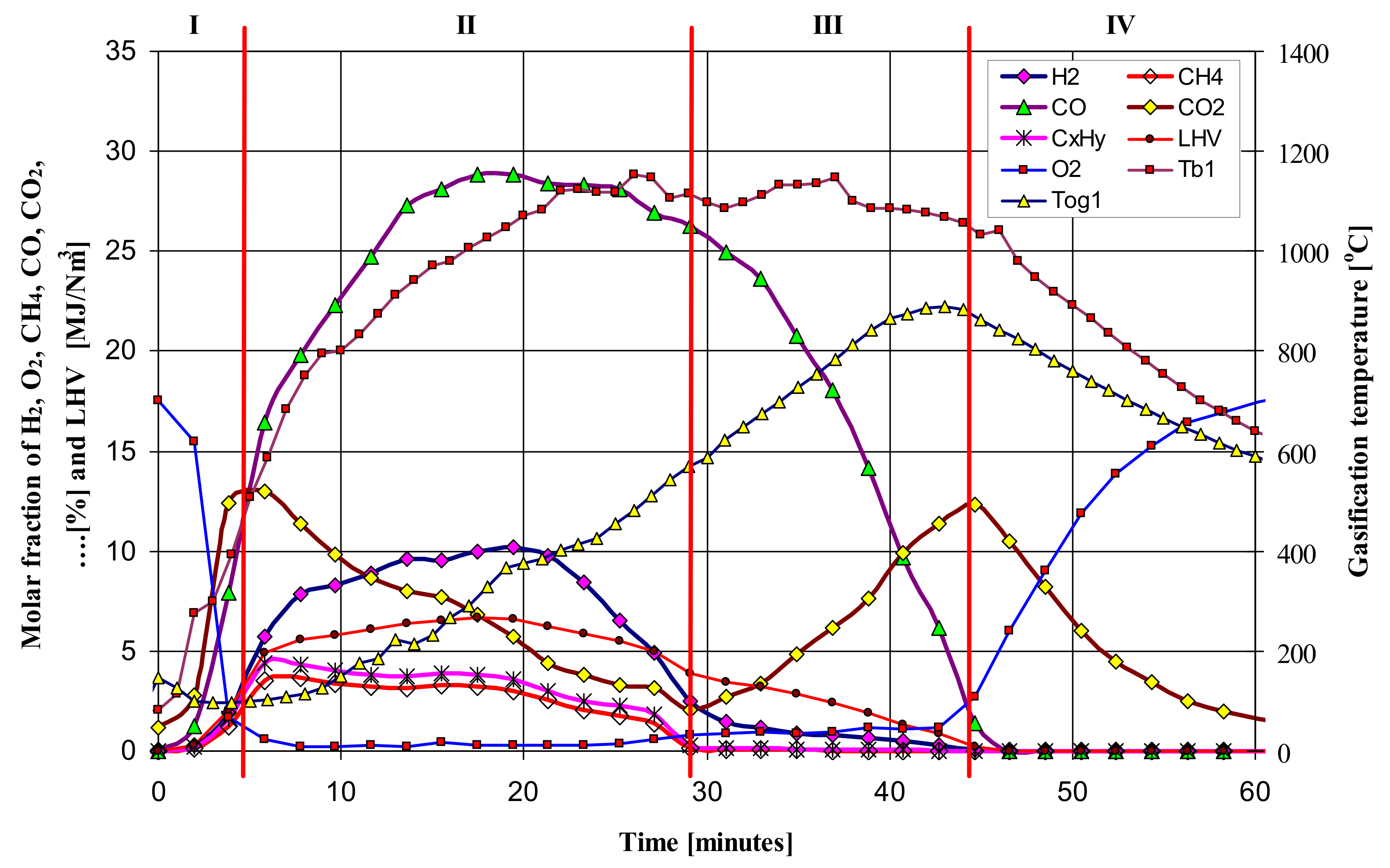
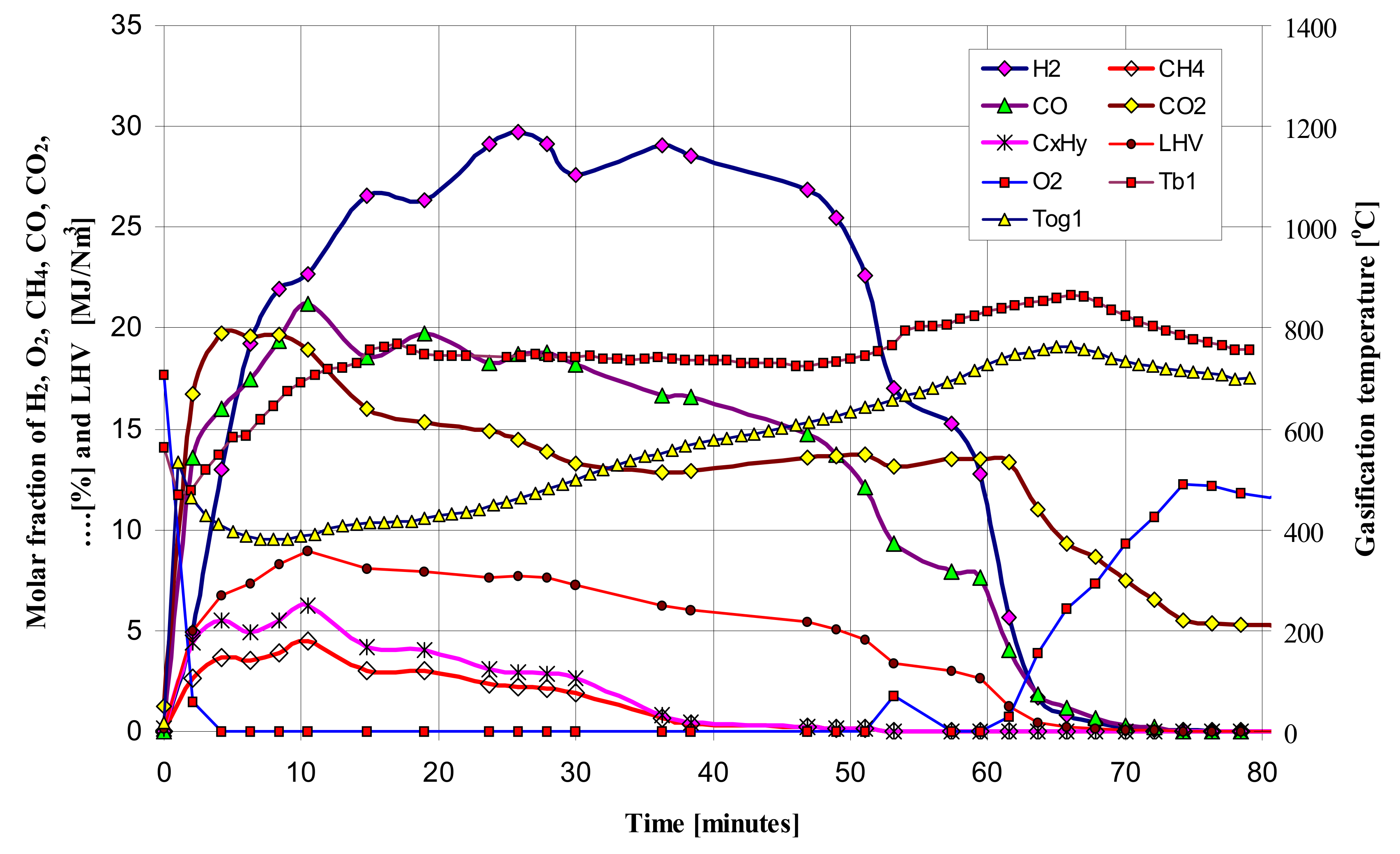
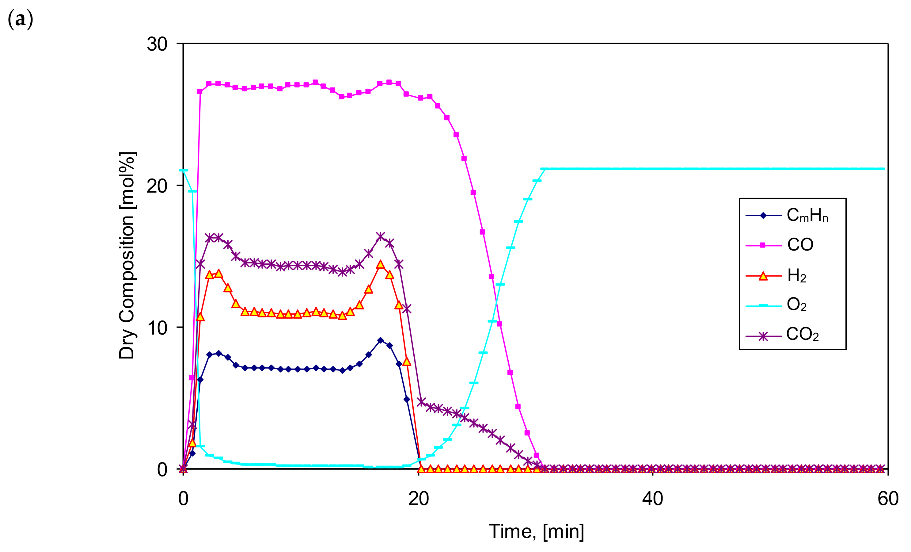
Figure 3 and
Figure 4 show the exemplary and temporal evolution of the resulting components of the produced gas fuel (syngas), its Lower Heating Value (LHV), bed temperature (T
b1) and the gas fuel temperature at the reactor outlet (T
og1). Comparing the gasification time, composition and LHV of the produced gaseous fuel, a clear effect of the vapor content in the feed gas on the increase in calorific value of the fuel can be noticed. The gasification time also increases from almost 45 min to 60–65 min, while the mole fraction of steam increases from 0% to 83%, respectively. The composition of the produced gaseous fuel varies, although the maximum LHV value is about 8 MJ/Nm
3. As expected, the steam content in the feed gas positively influenced the increase in the amount of hydrogen H
2 in the produced fuel from 10% to even 28%, corresponding to the increase in the molar proportion of steam in the gas.
By analyzing the obtained results of fuel gas composition and temperature of the bed of the updraft fixed bed batch type gasifier, four distinguishable phases are proposed. The proposed phases are numbered as I, II, III, and IV. It is important to distinguish the proposed phases from the four zones often referred to during the gasification process (combustion, reduction, pyrolysis and drying). Details regarding the phenomena occurring in each phase are given in [
4,
5].
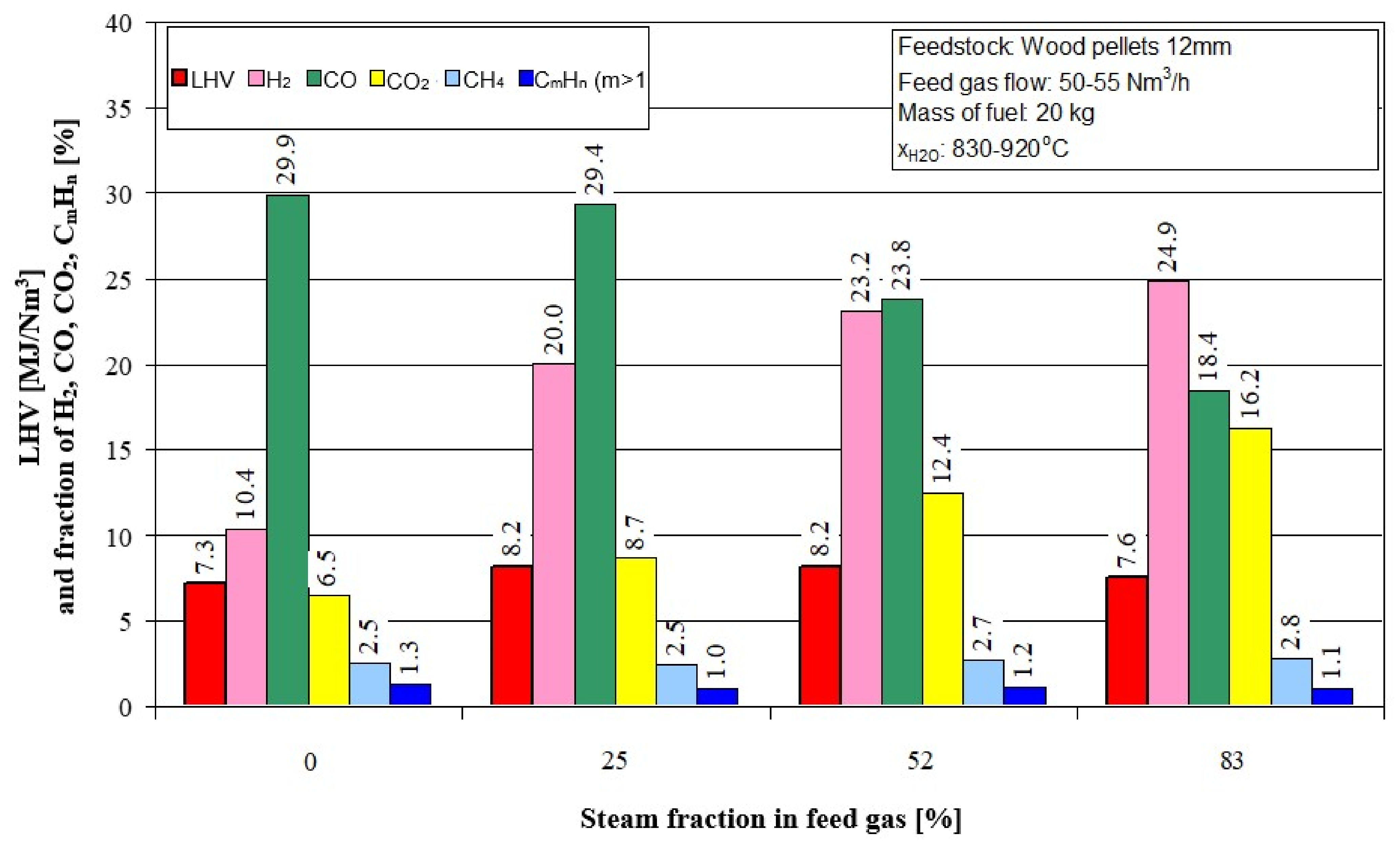
Figure 5 shows the effect of the steam fraction in feed gas on the calorific value (LHV) gas fuel and its chemical composition. The proportion of water vapor in the feed gas increases the calorific value of the gaseous fuel (LHV), but only to a value not greater than approximately 50%. A further increase in the proportion of water vapor reduces the LHV calorific value.
5.1. Amount of the Produced Gas Fuel and Its Calorific Value
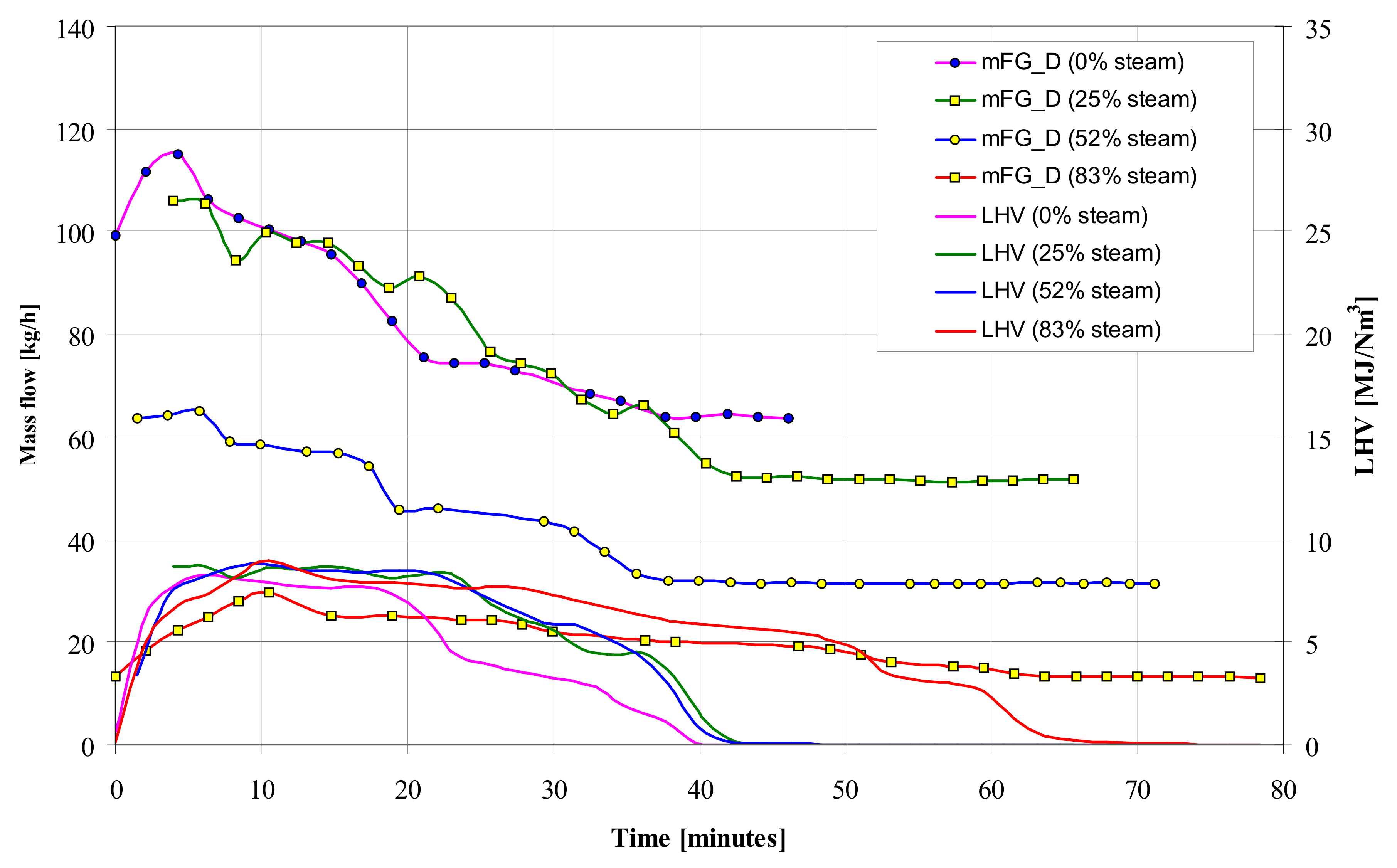
Comparison of gasification of wood pellets with air and a mixture of air and steam showed a negative effect of steam on the amount of the produced gas fuel, although its LHV calorific value slightly increased with the simultaneous extension of the reaction time (
Figure 6). The flow rate of the gaseous fuel produced during the gasification process with a mixture of air and steam is much lower than when only air is used as the feed gas.
5.2. Process Temperatures (Tb1 and Tog1)
For a more precise understanding of the gasification process, two characteristic temperatures T
b1 and T
og1 were continuously measured, where: T
b1 temperature is the temperature directly above the grate and the T
og1 temperature is the temperature of the produced gas fuel (syngas). Both temperatures are referred to as process temperatures.
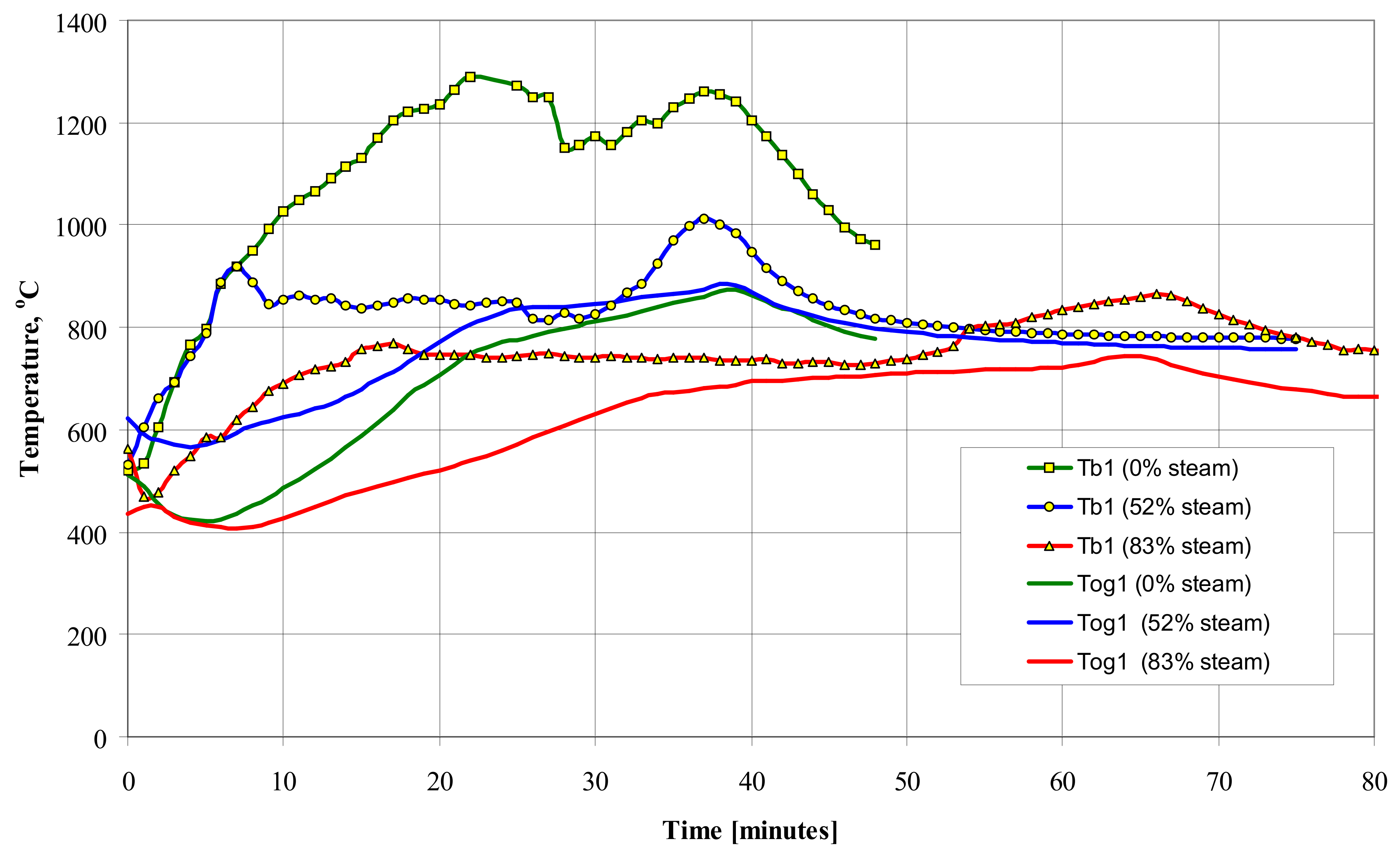
Figure 7 shows the influence of the feed gas composition on the T
b1 and T
og1 temperature values during gasification of wooden pellets.
Increasing the proportion of water vapor in the feed gas causes an increase in the amount of hydrogen H2 and a decrease in Tb1 temperature due to the endothermic reaction with carbon C and carbon monoxide CO.
5.3. Summary of the Experimental Studies
Summary of the experimental studies of gasification of biomass in the form of wooden pellets with the use of high-temperature air or a mixture of air and water vapor allows drawing the following conclusions:
- (a)
an increase in the proportion of water vapor in the feed gas reduces the temperature of the gasification process, reduces the amount of the produced syngas and carbon monoxide, but, at the same time, increases the molar proportion of hydrogen H2;
- (b)
increasing the temperature of the gasifying medium reduces the amount of produced tar, coke breeze and coke and significantly increases the calorific value of the produced LHV gaseous fuel (syngas);
- (c)
increasing the temperature of the process also increases the efficiency of the gasification process, the appropriate selection of the composition of the air and water vapor mixture allows a favorable process due to energy effects and the reduction of the emission of harmful carbon, sulfur and nitrogen compounds;
- (d)
an increase in the calorific value of the produced gas and the molar content of hydrogen H2 and hydrocarbons in it are obtained at higher temperatures of the gasification medium.
6. Numerical Modeling of Biomass Gasification as a Hydrocarbon Fuels
The next stage of the research consisted in the analytical and numerical modeling of flows with thermo-chemical reactions [
25,
26,
27,
28,
29] using the ANSYS Fluent CFD software [
30]. This software package enables numerical modeling of such processes as combustion and gasification. On the basis of various turbulence models, such as LRN, k-ε, RSM, DNS, LES, it also enables the modeling of compressible gas flows and allows testing own functions physical–chemical and exothermic or endothermic reactions.
During the gasification process which takes place in the presence of oxygen, the moisture, volatiles and char fractions are removed from the solid matter by drying, pyrolysis and gasification, respectively. The biomass fuel can be considered to consist of four components: moisture, volatile matter, fixed carbon (char) and ash. The energy required for drying, pyrolysis and gasification is obtained by partial combustion of carbon and hydrogen occurring in biomass. These processes take place simultaneously within the reactor. Heat and mass transfer across the bed is coupled with moisture evaporation, biomass pyrolysis, char combustion and gasification, gas-phases reactions, and, particularly, the effect of mixing between the volatiles and feed gas on the volatiles consumption is taken into account.
In the case of an updraft type batch reactor (gasifier), the gasification process takes place in an unsteady state through the flow of high temperature air from the bottom up through the biomass fuel. Characteristic layers are formed in the deposit, in which individual gasification stages take place: from the bottom there is a layer of ash, combustion, coke gasification, degassing and drying of biomass (
Figure 2). The heat for the alternation comes from partial combustion. In the numerical modeling of gasification process in a batch reactor, it is assumed that gas phase, which is usually air or a mixture of air and water vapor, flows through the solid bed in the form of granules. Also, it is assumed that the ignition phase of biomass is caused by the existence of hot oxidizer. The calculated cases of the analysis are presented in
Table 1. The height of the gasifier is 750 mm with an internal diameter of 347.1 mm and the cross section area of 0.1256 m
2. It was assumed that the overheated oxidant with a uniform flow field is delivered directly under the bed. Additionally, it was taken into account that the gaseous fuel leaves the gasifier in its upper part. The entire gasifier was divided into 512,050 unstructured cells and the process run time for all cases was 5 s. The temperature and velocity of the supplied gas were set as boundary conditions and the distribution profiles of these parameters were assumed to be homogeneous. In all cases, the hydrocarbons were included in the C
mH
n form.
The results of numerical calculations of the gasification process were verified with measurements obtained from experimental tests. Among other things, the influence of temperature, the amount of feeding gas and the type of fuel (biomass) on the gasification process were examined.
6.1. Influence of the Feed Gas Temperature
During the gasification process, hydrogen H
2, carbon monoxide CO and oxygen O
2 were obtained as the main products of this phenomenon. It should be noted that the results of the gas composition measurement conducted at the outlet of the gasifier and the prediction data, obtained in the upper part of the gasifier, are of the same nature. The maximum concentration values of all components are similar. The highest values of CO and H
2 concentrations occur in the same gasification period and show good compliance proving correct numerical modeling.
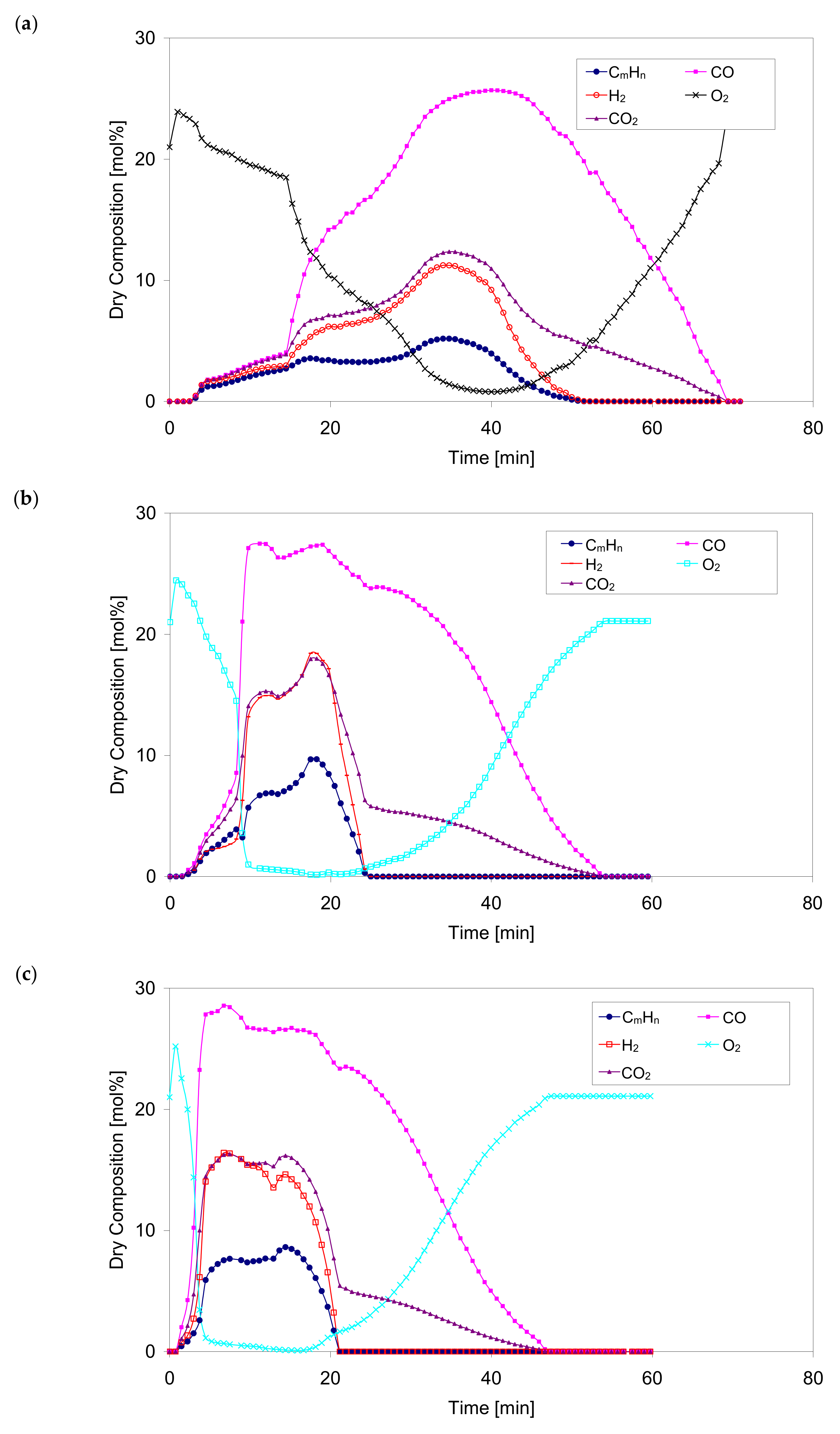
Figure 8 shows the concentration of the main components during the gasification process for different values of the oxidant temperature ranging from 350 °C to 830 °C.
The percentages of gasification components during the process for the selected superheated oxidant temperatures are qualitatively similar. With an increase in the temperature of the oxidant, the maximum values of the gaseous components of the process are obtained after a much shorter heating period which seems to be a correct tendency and is confirmed by experimental measurements.
Based on the results of numerical calculations,
Figure 8, a rapid drop of the oxygen content in the gaseous products leaving the bed was observed, as well as a temporary shortening of the process when the temperature of the oxidizer increased. For example, for case No. 2,
Table 1 (oxidizer temperature 530 °C), the oxygen O
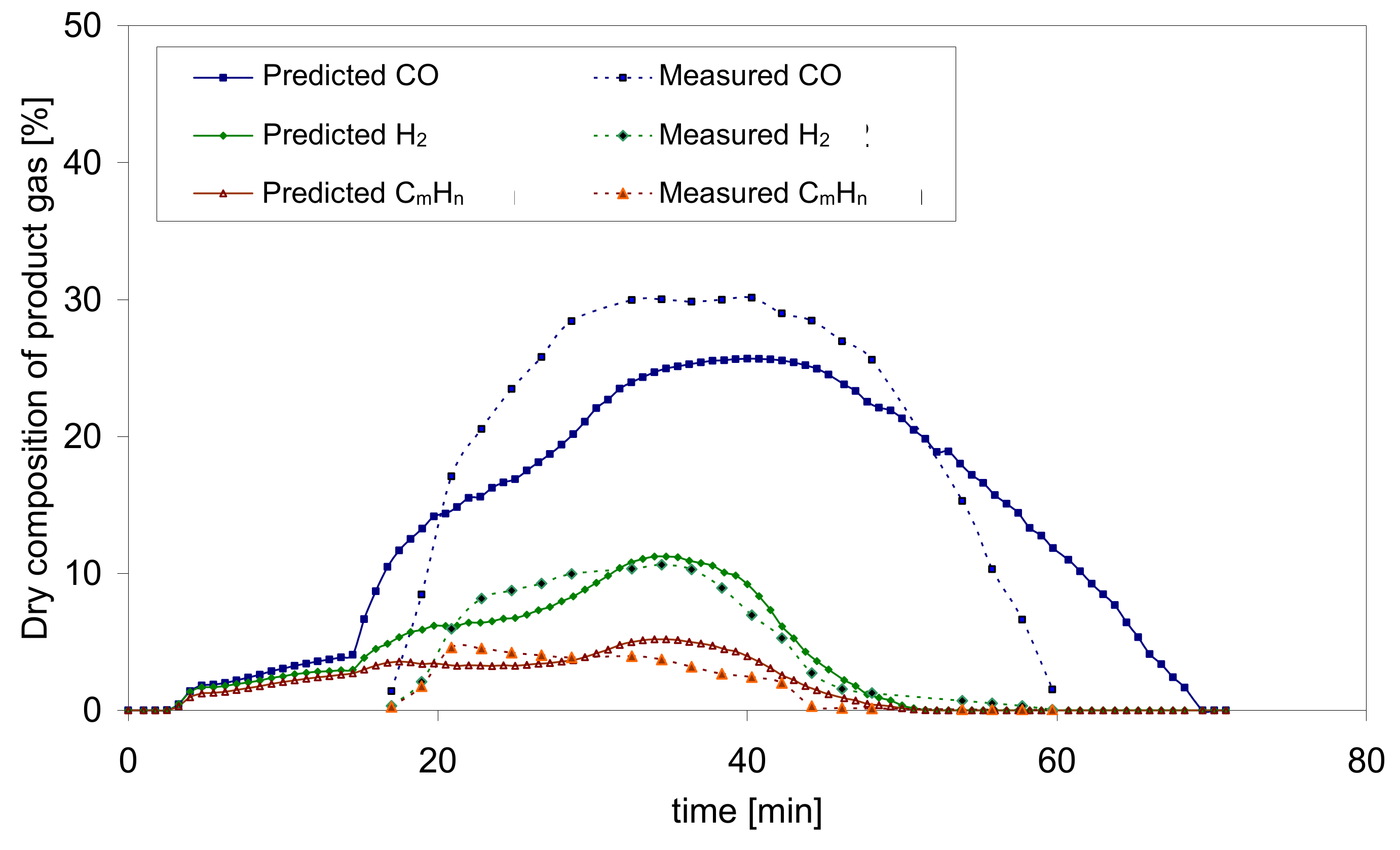
2 level decreases from 21% to almost 1% in 540 s. For cases Nos. 3, 4, 5, this time is 225 s, 150 s and 100 s respectively. In the same period, there was a fast increase in the concentration of carbon monoxide CO. For case No. 1, the composition of the gaseous products remains high and unchanged for a relatively long period of time. At this stage, the concentrations of CO, H
2 and C
mH
n reach their maximum values: 25.7, 11.2 and 5.2 (dry vol.%), respectively. The measured concentration values of CO and H
2 for the same case are 28.8 and 10.2 (dry vol.%) respectively. The compliance between the results obtained from the calculations and the measurements can be considered as satisfactory. Additionally, the maximum values reach a slight increase with increasing oxidizer temperature. For example, for case No. 5, the calculated maximum values of CO, H
2 and C
mH
n are 29.5, 18.6 and 9.8 (dry vol.%), respectively. Compared to case No. 1, this increase is 14.7%, 66.1% and 88.5% respectively.
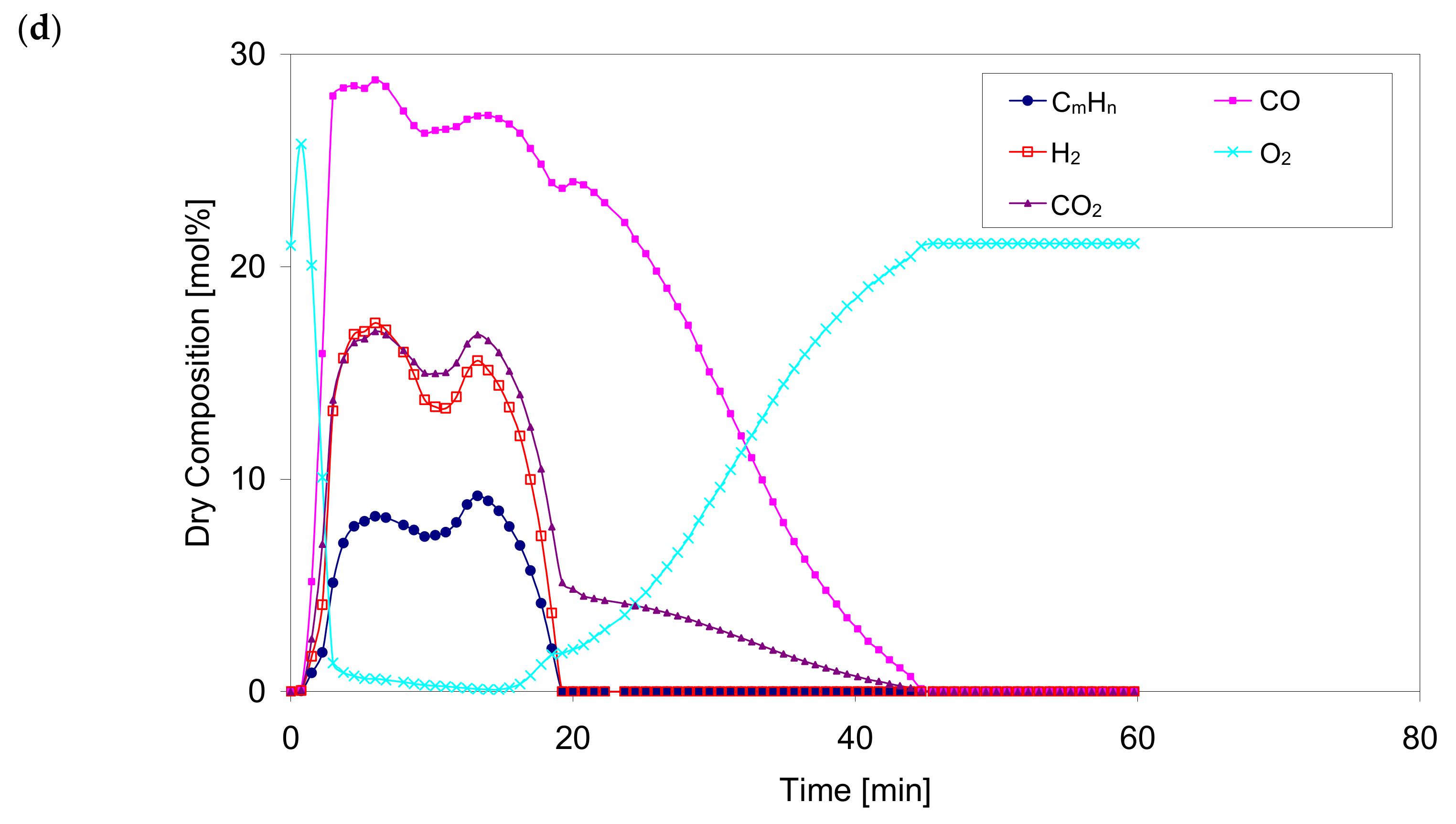
The oxygen O2 concentration increases and then decreases sharply in all cases. The entire gasification process takes place with a predetermined increase in the oxygen O2 concentration to an ambient value of 21% (vol.), with a simultaneous decrease in the content of all gaseous combustible components and CO2 to 0%.
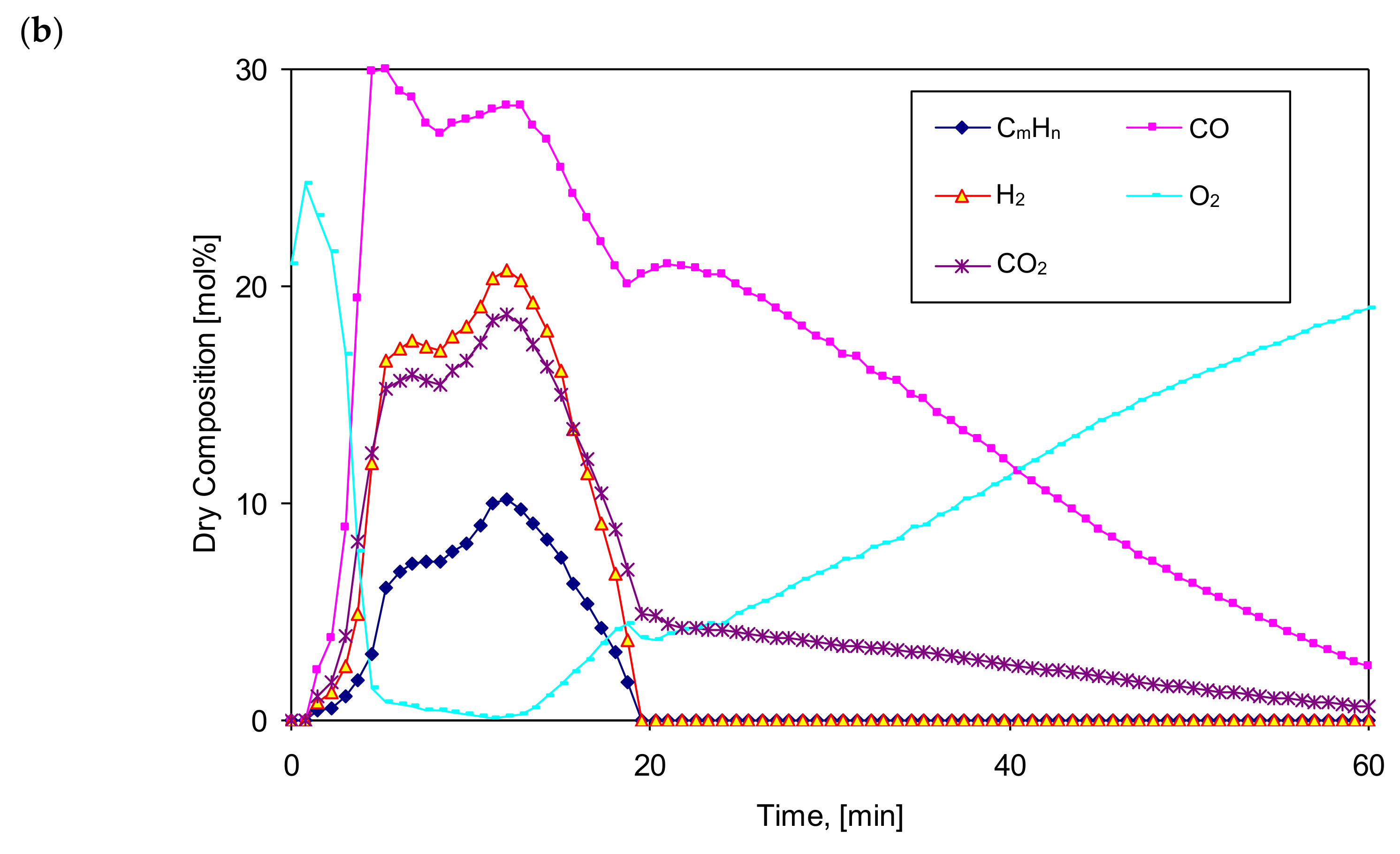
Figure 9 presents a comparison of the results of numerical calculations and experimental measurements of the gasification process of biomass in the form of pellets for case No. 1,
Table 1.
Summarizing the above, it can be stated that very fast gasification process influences the separation of a large amount of pyrolytic gases in a relatively short time and the maximum molar fractions of combustible components such as carbon dioxide CO2, methane CH4 and hydrogen H2 formed earlier and at a higher oxidizer temperature when fed with a lower temperature oxidizer. Light hydrocarbons are produced in much higher amount (concentration) at high temperatures of the feed gas. However, the high temperature of the oxidizer allows the bed temperature to exceed 1000 °C during the main gasification stage. This temperature most often affects the formation of not only carbon monoxide CO, mainly as a result of the Carrasse reaction, but also the formation of large amounts of hydrogen H2.
6.2. Influence of the Oxidizer Volumetric Flow
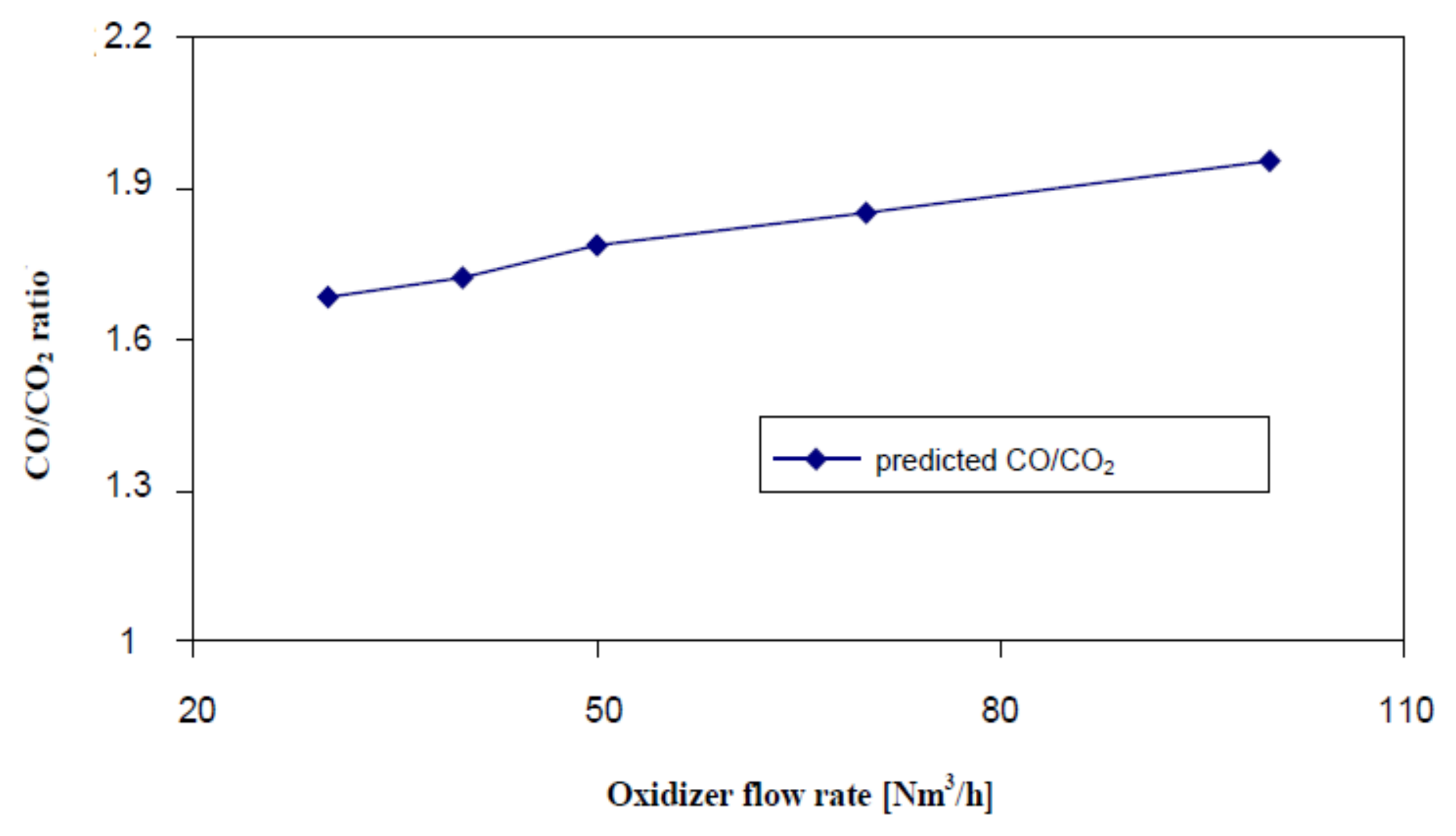
Figure 10 shows the impact of the amount of feed gas on the gasification process, especially the CO/CO
2 concentration ratio and the biomass mass left on the grate. The CO/CO
2 concentration ratio was calculated for the main gasification process, where the hydrogen H
2 is formed. The gasification process was investigated for various values of the feed gas amount: 30, 40, 50, 70 and 100 Nm
3/h respectively.
The increase in the CO/CO
2 ratio occurs with the increase of the supplied amount of oxidizer.
Figure 10 shows clearly that the amount of the introduced feed oxidizer controls the amount of gas produced during the conversion process and, therefore, the rate of the gasification process. This leads to the gas having a higher calorific value. This is due to high temperature in the reactor which intensifies the gasification reactions and the formation of hydrogen H
2 and carbon monoxide CO.
Another obvious factor to speed up the gasification process is the flow rate of the feed gas. For example, for 20 kg of wood pellets of 12 mm diameter and a feed gas temperature of 530 °C, when its volumetric flow rate increases from 30 Nm3/h to 100 Nm3/h, the total gasification time is 4500 s and 2250 s respectively. It is two times shorter. The reason for this may be the temperature of the bed and the presence of oxygen O2 increasing with a greater flow of feed gas.
6.3. The Type of Fuel Impact
Figure 11 shows the influence of pellet size on the gasification process. Undoubtedly, smaller diameter wooden pellets are subject to faster overheating and pyrolysis. For example, in the case of gasification of 20 kg pellets with a diameter of 6 mm, the volumetric flow rate of the oxidizer at a temperature of 830 °C is 50 Nm
3/h, the oxygen level O
2 drops from 21% (vol.) to about 1% in just 90 s. For pellets with a diameter of 19 mm, for example, the time is 270 s, i.e., it increases threefold. This is obvious since smaller pellets have a greater surface area to weight ratio.
The calculated maximum values of the gaseous fuel components concentration increase with the changes in pellets size. Smaller pellets in the bed affect the rate of the gasification process. For example, for pellets with a diameter of 6 mm, the gasification process time takes 1780 s, while for pellets with a diameter of 19 mm, the process time is 3600 s. This is due to the fact that an increase in the pellets size results in greater temperature gradients inside the pellets and a much lower temperature in their center.
Additionally, for smaller diameter pellets there is a more stable gasification zone for a relatively long time. The size of the granules also affects the pressure drop in the reactor. The smaller particle diameter results in a greater pressure drop which, in turn, results in a more uniform feed gas flow and better mixing of the biomass and oxidizer.
7. Conclusions
Fuel gas quality and product distribution obtained during gasification were studied by varying the preheating temperature and composition of the gasification agent (air/steam). Preheating of feed gas is realized by means of the uniquely developed high-cycle regenerative preheater. The higher temperature gasification concept combines the advantages of high heating rates involved and the efficient tar reduction, showing the capability of this technology for maximizing the gaseous product yield in an up-draft fixed bed gasifier. The higher heating rate favors also the decrease of tar formation in the charging period of a fixed bed gasifier. It was also observed that at a high temperature, steam addition contributed to the thermal conversion of biofuels to gas with higher production of hydrogen. Maximum flow rate of produced gas increases with the rising temperature and decreases with the increase of molar fraction of steam in the feed gas. Conducted experimental and numerical study proved that the higher temperature of the gasifying process yields cleaner gas of higher calorific value than in case of low-temperature processes, such as circulating, pebble bed or fluidizing bed gasification.
The results of numerical calculations allow drawing the following conclusions:
- (a)
an increase in the temperature of the supply gas accelerates the gasification process and increases the gasification capacity —higher molar proportions of hydrogen H2, carbon monoxide CO and hydrocarbons CmHn;
- (b)
the oxidizer temperature in excess of 530 °C has little effect on the amount of hydrogen H2, carbon monoxide CO and hydrocarbons CmHn, because it is the ignition temperature level of wood pellets;
- (c)
for the temperature of the oxidizer higher than the ignition temperature of the bed, the gasification process is more intensive;
- (d)
at higher oxidizer volumetric flow rates, the maximum values of the gaseous fuel components increase slightly while the gasification rate increases significantly;
- (e)
the smaller size of the pellet granulate accelerates the process of overheating and pyrolysis;
- (f)
with an increase in the size of the pellet granules, the maximum values of the components of the gas fuel increase, too;
- (g)
for pellets with a smaller diameter there is a more stable gasification zone for a relatively long time;
- (h)
good compliance of the gaseous fuel composition and their maximum values were obtained during the high-temperature gasification process in comparison with the measurement results.
Although a new continuous gasifier has already been built in KTH/GUT and a preliminary test has been conducted, there is still an urgent need to complete the system with required instrumentation and additional equipment just for a better understanding of the chemistry of gasification in extremely high temperatures. Extension of studies to be performed over different kinds of waste (tires or plastic car components) will require careful analysis of contaminants in slag as well as in the produced fuel gas. The main effort will be put on widening tested gasification conditions in a way that allows estimating the combined effect of feed gas temperature, composition, feedstock properties and feeding rate.


