Article

Asymmetric Flow Control in a Slab Mold through a New Type of Electromagnetic Field Arrangement

1
College of Petroleum Engineering, Liaoning Petrochemical University, Fushun 113001, China
2
Faculty of Science and Engineering, Bay Campus, Swansea University, Fabian Way, Swansea SA1 8EN, UK
3
Yangtze Delta Region Institute, Tsinghua University, Jiaxing 314006, China
*
Authors to whom correspondence should be addressed.
Processes 2021, 9(11), 1988; https://doi.org/10.3390/pr9111988
Submission received: 9 October 2021 / Revised: 4 November 2021 / Accepted: 5 November 2021 / Published: 8 November 2021
(This article belongs to the Section Process Control and Monitoring)

Abstract

:
This research aims to investigate the control effect of asymmetric flow in a slab mold using a novel magnetic field arrangement: freestanding adjustable combination electromagnetic brake (FAC-EMBr). Three scenarios (submerged entry nozzle moves to the narrow face, wide face of the slab mold, and rotates 10°) were studied using three-dimensional numerical simulation. The results show that the magnetic field generated by the FAC-EMBr system can effectively cover three key zones in mold and that the magnetic flux density in the zone cover by a vertical magnetic pole can be adjusted according to the actual flow condition. The FAC-EMBr can effectively improve the asymmetric flow in a mold and near the narrow surface caused by the asymmetric arrangement of the nozzle and can effectively inhibit the occurrence of the flow deviation phenomenon and stabilize the steel/slag interface fluctuation. At the same time, FAC-EMBr has obvious inhibition effects on the surface velocity and can optimize the asymmetric distribution of the surface velocity and the upper reflux velocity caused by the asymmetric arrangement of the nozzle. This study can provide theoretical evidence for the development and utilization of a new electromagnetic brake technology.

1. Introduction

In the process of continuous casting, the improper operation or the change of operation process, such as mold oscillation, submerged entry nozzle (SEN) clogging, or SEN misalignment (eccentric SEN location), often cause problems of SEN partial clogging, SEN offset, and even rotation [1,2,3,4,5,6,7]. These phenomena aggravate the asymmetric flow behavior of molten steel and then cause bias flow, vortex flow, and slag entrapment, which reduce the slab quality [8,9,10]. In the case of high casting speed, the asymmetric arrangement of SEN has a more obvious influence on the flow pattern of molten steel and the fluctuation of steel/slag interface, which further affects the slab quality [11,12]. The asymmetric flow leads to the uneven growth of solidified shells and to the formation of cracks [9].
In order to solve the quality problem of continuous casting slabs caused by asymmetry flow, some methods were usually adopted, such as optimizing the position of the SEN, replacing the blocked nozzle in time, adjusting the position of slide gate, etc. [8]. In addition, the application of electromagnetic brake (EMBr) with a stable magnetic field is also used to suppress the bias flow caused by improper process parameters or operation [10,11,12]. The EMBr is an efficient and nonintrusive way to control the turbulent flow pattern, and its stability in the nozzle and the mold region [13]. The EMBr technology can solve the problem of turbulent flow of molten steel caused by a high casting speed. According to the different arrangement of the applied magnetic field, the forms of electromagnetic brake mainly include Local EMBr, EMBr ruler, FC mold, Vertical electromagnetic brake, and some new forms of electromagnetic brakes [14,15,16,17].
Many researchers have studied asymmetric flow under the effect of a steady magnetic field [1,2,8,10,18,19,20]. Li et al. studied the effect of EMBr on vortex flow in the thin slab continuous casting mold. The simulation results showed that the EMBr can significantly suppress the eddy current vortex flow and change the shape of vortex, but it cannot completely eliminate it [12]. Xu et al. established a three-dimensional mathematical model to describe the transient flow phenomenon in the funnel-shaped mold of CSP under the effect of EMBr and studied the effect of magnetic flux density on the flow field. The results showed that the bias flow in the funnel-shaped mold can be obviously reduced by using EMBr [21]. It can be inferred from previous work that the EMBr technology (Local EMBr, EMBr ruler, and FC mold) can inhibit the asymmetric phenomenon of the flow field caused by bias flow to a certain extent but because the magnetic field arrangement is usually symmetrical about the nozzle, the magnetic pole position is often fixed, and the flexibility of the traditional electromagnetic brake for inhibiting bias flow is not very good. On the basis of previous studies, a type of magnetic field arrangement, FAC-EMBr [22], was introduced to suppress and alleviate the mold bias flow. The characteristic of the FAC-EMBr is that the vertical magnetic pole (VP) and the horizontal magnetic pole (HP) can be independently supplied with current. Additionally, that position of the VP can be adjusted according to the actual flow state. Therefore, the application of FAC-EMBr can not only control the molten steel flow and the level fluctuation in a high casting speed slab mold but also realize the suppression of bias flow in the mold by adopting symmetrical or asymmetrical magnetic field arrangements, thus providing sufficient time for actual operation and adjusting the production process. The magnetic field arrangement of FAC-EMBr is shown in Figure 1.
In this paper, the behavior of molten steel flow and the fluctuation of steel/slag interface in the FAC-EMBr mold were numerically simulated, considering the influence of asymmetric arrangement of SEN (asymmetric in thickness direction, asymmetric in width direction, and rotating SEN). It can provide theoretical support for the development and utilization of new electromagnetic brake technology.

2. Mathematical Model Setup

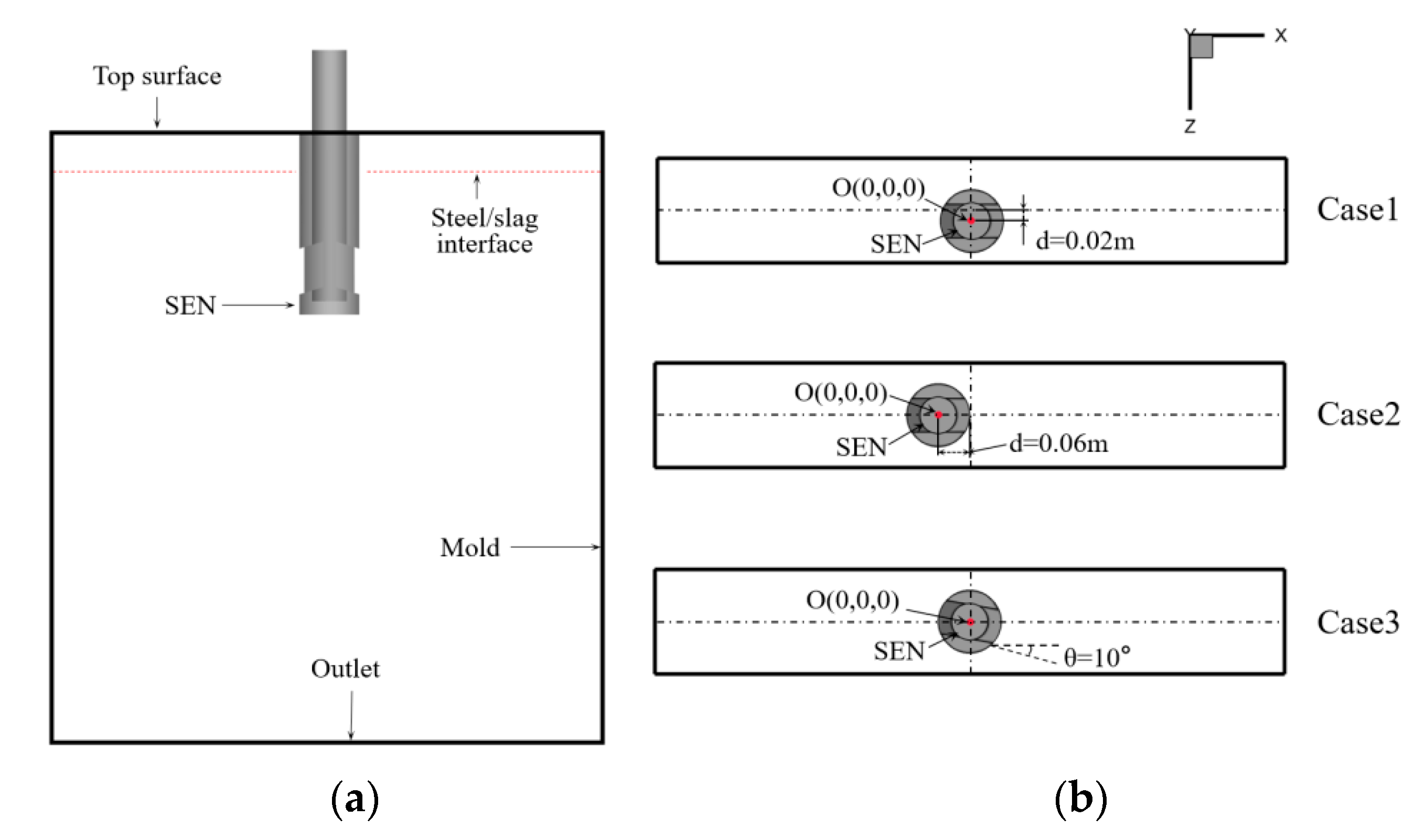
2.1. Asymmetrical Arrangement of SEN

Three types of SEN asymmetrically arranged were studied in this paper, which were offset to wide face, offset to narrow face, and SEN rotation, as shown in Figure 2. The first asymmetrically arrangement of the SEN was along the mold thickness direction (Case 1), and the SEN was located 20 mm off-center. The second arrangement of the SEN was along the mold width direction, and the SEN was moved 60 mm from the centre (Case 2). The third arrangement was to rotate the SEN clockwise along the y-axis by 10° (Case 3).

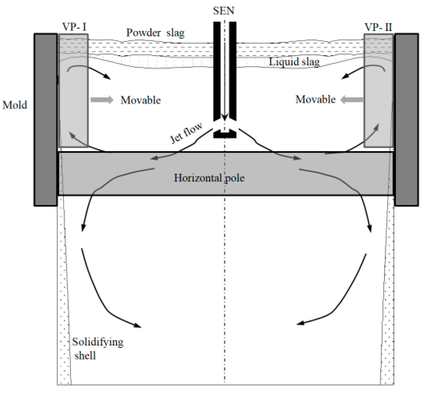
2.2. Configuration of FAC-EMBr

The fluid region, the geometrical size of the FAC-EMBr magnetic pole and different views for three types of SEN asymmetrically arrangements are shown in Figure 3. Two pairs of VP (VP-Ⅰ and VP-Ⅱ) are arranged on the wide face nearby the narrow face. The cross-sectional dimensions of the VP are 0.42 m × 0.1 m (height × width), and the cross-sectional dimensions of the HP are 1.2 m × 0.15 m (width × height). The geometrical dimension of that fluid zone in the mold is 1.2 m × 0.1 m × 2.53 m, and the thickness of the liquid slag layer is 0.03 m. The immersion depth of SEN is DSEN = 0.18 m, and the port angle of SEN is θp = −15°. The material properties and simulation parameters are shown in Table 1.

2.3. Governing Equation and Boundary Conditions

The behavior of molten steel flow and level fluctuation under the effect of steady electromagnetic field can be described by Navier–Stoke’s equations and the VOF equation, together with Maxwell’s equations, which can be found in References [23,24].
In this study, the mold inlet is set as the speed inlet and the specific value can be calculated by the actual casting speed of 1.8 m/min. The exit is set to the outflow boundary condition: the diffusion flux for all flow variables normal to the exit is zero. The top surface above the liquid slag layer is set to the free surface condition: normal velocity and gradients of all variables are set to zero. The mold walls comprising two wide faces and two narrow faces were set in the non-slip boundary condition.

2.4. Mesh Independence Test and Validation

In this paper, the non-structural hexahedral mesh was adopted. The meshes at two phase interface (steel/slag) and near the mold wall region were refined. The mesh in the fluid region is shown in Figure 4 (mesh for Case 3). The procedures of the mesh independence test and mathematical model validation can be found in References [23,24].

3. Results and Discussion

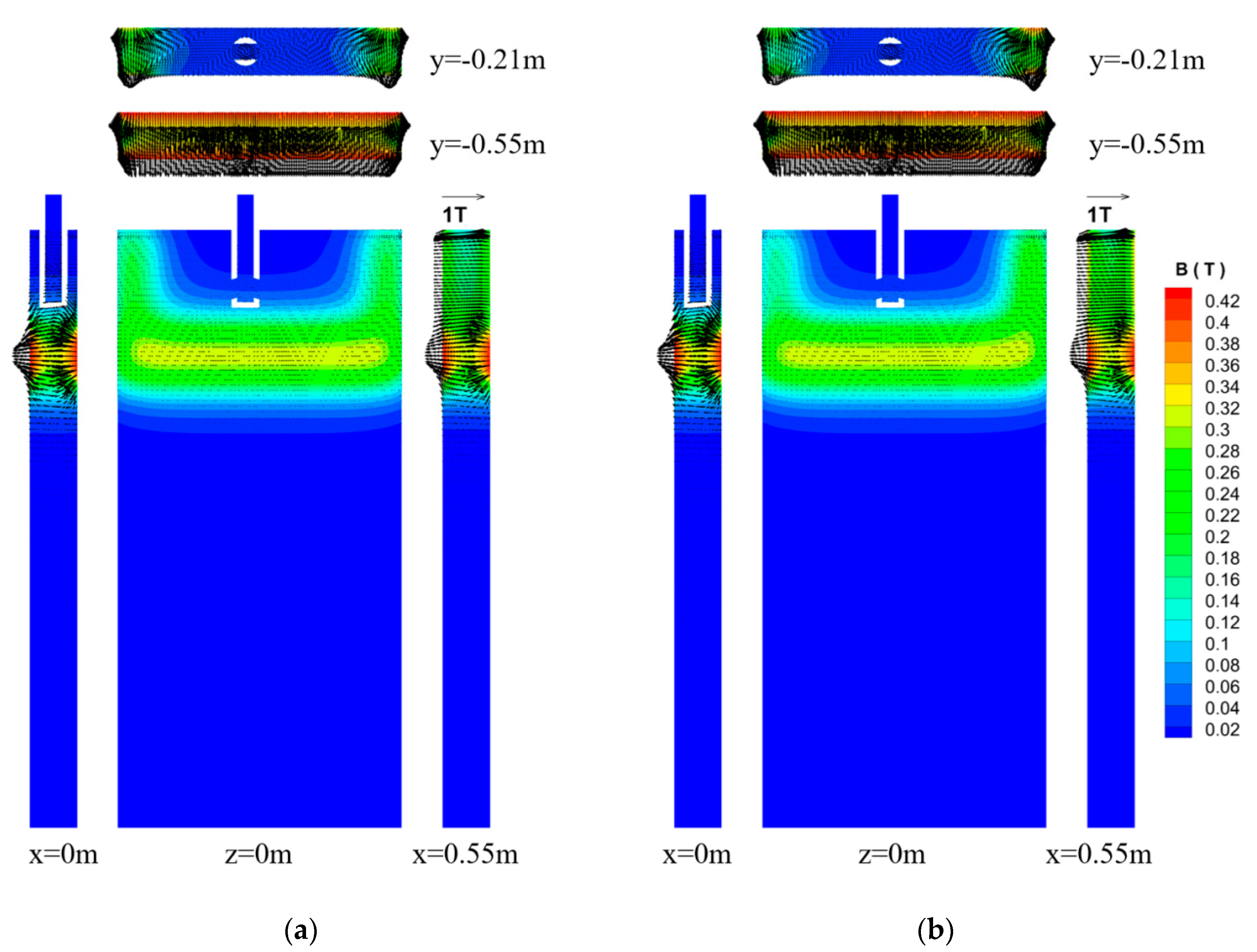
3.1. Magnetic Flux IntensityDistribution

The magnetic pole arrangement and current input mode of the FAC-EMBr are completely different from those of the traditional electromagnetic brake device. Figure 5 shows the vector distribution and contour of the magnetic flux intensity under the conditions of SEN misalignment (Case 1) and different VP currents. Wherein the casting speed is 1.8 m/min, the immersion depth DSEN is 180 mm, and the port angle θp is −15°. From Figure 5a,b, it can be seen that the uniformly distributed magnetic field was formed both below the SEN and in the meniscus region near the narrow face after the application of FAC-EMBr. As the input current value IVP-Ⅰ = IVP-Ⅱ < IHP, the magnetic flux intensity in the region covered by the HP is greater than that in the region covered by the VP, and the magnetic flux intensity near the wide face is greater than that inside the mold.
From Figure 5b, it can be seen that, when different currents are applied to the VP, the magnetic flux intensity is uniform in the meniscus region near the narrow face of the mold, but since IVP-I < IVP-II < IHP, the magnetic flux intensity in the left meniscus region is significantly smaller than that in the same position in Figure 5a.

3.2. Effect of SEN Position and Magnetic Field on Molten Steel Flow

To further analyze the influence of SEN position and FAC-EMBr on the flow behavior of molten steel, the isosurface of molten steel flow velocity(Vsteel = 0.2 m/s) and steel/slag interface (Volume fraction of αsteel = 0.5) under different conditions were established. In addition, to analyze the impinging influence of molten steel jet on the narrow surface, the velocity contour in the crosssection of x = ±0.595 m were taken for analysis. The distribution of the molten steel surface velocity (line y = −0.03 m) in the mold was quantitatively analyzed. Wherein the casting speed VC = 1.8 m/min, the port angle of SEN θp = −15° and the SEN immersion depth DSEN = 180 mm.

3.2.1. Effect of SEN Position and Magnetic Field on the Velocity

Figure 6 shows the isosurface diagram of the molten steel (Vsteel = 0.2 m/s) with and without FAC-EMBr. At the same time, the distributions of the steel/slag interface under the condition of Case 1 were also displayed in the figure.
As shown in Figure 6, in the case without the application of FAC-EMBr, the flow velocity in the impact region, the lower recirculation region, and the meniscus region all reach 0.2 m/s. The impingement depth of the lower backflow region is relatively large, and the velocity isosurface is asymmetrically distributed in the z = 0 section. The asymmetric distribution of velocity forms bias flow, which is not conducive to the floating removal of inclusions and bubbles, and easily forms defects in the slab [12]. At the same time, it can be found that, when the FAC-EMBr is not applied, the molten steel velocity in the upper backflow and meniscus regions are too large, which lead to the liquid slag layer being pushed away by molten steel (forming slag holes).At this time, the secondary oxidation occurs when the high-temperature molten steel contacts air, and finally the quality of the continuous casting slab is reduced. Due to the asymmetric arrangement of the SEN in the thickness direction, the breakout area is also closer to the wide face. With the application of FAC-EMBr, the velocity in the upward backflow and meniscus regions were all significantly reduced, and the slag holes were also eliminated. The meniscus wave height ∆y [24] was reduced from 41.2 mm to 8.9 mm. Under the brake effect of FAC-EMBr, the velocity in the upper and lower backflow regions, meniscus region, and mold interior decrease obviously and the steel/slag interface near the narrow face is relatively stable and is not pushed away by the upper backflow.
Figure 7 shows the isosurface diagram of molten steel (Vsteel = 0.2 m/s) and the steel/slag interface under the condition of Case 2 with and without FAC-EMBr. From Figure 7a, it can be seen that, in the case without FAC-EMBr, when the SEN position is close to the narrow face, the velocity contour shows obvious asymmetry and the impact depth of the lower backflow on the left side is obviously smaller than that on the right side. This is because the SEN is close to the left narrow face, the left molten steel jet impacts the narrow face earlier, and the velocity reduction in the jet flow on the left is larger than that on the right. The asymmetric arrangement of the SEN along the width direction has little influence on the symmetry velocity distribution along the z-axis direction. It can also be seen that the slag hole phenomenon appears near the narrow face on the right side of the mold, and although it does not appear on the left side, the meniscus wave height value is also very large, reaching 30.4mm. Under the effect of FAC-EMBr (Figure 7b), the velocity in the meniscus region and the impact depth of the lower backflow are effectively suppressed, and the surface velocity is also significantly reduced. The asymmetrical arrangement of the SEN along the width direction makes the velocity of the lower backflow on the left increase slightly and that on the right side decrease slightly. However, compared with the case in which the FAC-EMBr is not applied, the symmetry of velocity distribution is greatly improved. At the same time, it can be found that, after applying the FAC-EMBr, the slag hole on the right side of the mold is eliminated, the violent fluctuation of the meniscus on the left side is also effectively suppressed, and the meniscus wave height ∆y is reduced from 30.4 mm to 15.4 mm.
In the case of changing VP current (Figure 7c), since the horizontal pole current remains unchanged, the current change of the VP has less influence on the impact depth of the lower backflow. The velocity in the meniscus region increases or decreases with the changing of the VP current. This shows that the VP has a good suppression effect on the velocity in the meniscus region and that it is flexible and adjustable. After changing the current of the VP, although the level fluctuation on the right of the mold is further suppressed, the wave height ∆y of the left meniscus increases slightly from 15.4 mm to 19.7 mm due to the decrease in the current of the left VP.
Figure 8 shows the isosurface of the molten steel (Vsteel = 0.2 m/s) and the steel/slag interface under the condition of Case 3 with and without FAC-EMBr. As shown in Figure 8a, because of the rotation of SEN, the jet flow impinges on the wide face and the narrow face at the same time to form the upper and lower backflow. At the same time, a backflow is formed on the wide surface side, which is not impinged by the molten steel jet, and the impact depth of the lower backflow on this side is obviously increased. The velocity in the meniscus region in the case of SEN rotation is significantly less than the velocity in the cases of Case 1 and Case 2 without electromagnetic braking. Under the effect of FAC-EMBr, the velocity of the lower backflow is obviously restrained and the asymmetry of the downward backflow on the wide face is obviously improved. Additionally, the backflow formed on the side of the wide face that is not impacted by the molten steel jet is weakened. The velocity of molten steel in the meniscus region is also reduced. In the case of SEN rotation (Case 3), the higher impingement velocity is mainly concentrated in the lower backflow region, and the lower velocity is in the upper backflow and meniscus region, so the level fluctuation becomes more flat, and the meniscus wave height ∆y is only 6.2 mm. After the addition of FAC-EMBr, the level fluctuation is further suppressed, and the meniscus wave height ∆y is reduced to 5.7 mm.

3.2.2. Effect of SEN Position and Magnetic Field on the Velocity

Figure 9 shows the velocity contours in the x = ±0.595 m section for different SEN locations and electromagnetic parameters. It can be seen from Figure 9 that the asymmetric arrangement of the SEN significantly affects the velocity distribution and that the velocity also changes greatly when the arrangement of the SEN is changed.
Under the condition of Case 1, the upper and lower backflow regions with larger velocity values are formed on the narrow face. In the absence of EMBr (Figure 9a), the speed near the left wide face is significantly greater than that near the right, and the depth of impact is also greater than that on the right side. After applying FAC-EMBr (Figure 9b), the velocity values at the upper and lower parts of the impact point are significantly reduced, the velocity near the narrow surface is also symmetrically distributed, and the impact depth of lower backflow is also significantly reduced, which helps in the floating removal of inclusions and in improving the slab quality. Under the condition of Case 2 (Figure 9c), the velocity near the narrow face is symmetrically distributed with respect to the z = 0 section, but the velocity near the narrow faces on the left and right sides is quite different. This is because SEN is close to the left side of the mold under the Case 2 condition, and the jet impinges on the narrow face of the left side to form the upper and lower backflow regions with larger velocity. However, the right narrow face is far from the SEN, the molten steel jet deflects upward before impacting the narrow surface of the mold, forming an upper backflow with a larger velocity at the upper part of the impact point, and the velocity at the lower part of the impact point is much smaller. Under the effect of FAC-EMBr (Figure 9d), the horizontal magnetic field and the vertical magnetic field have a significant brake effect on the jet flow and the flow near the narrow face, and the velocity near the narrow face is significantly reduced. When the current parameters of the VP are changed (Figure 9e), the velocity near the left narrow face increases slightly but decreases near the right narrow face. This shows that the increase in current intensity of VP helps reduce the velocity of molten steel in the upper and lower backflow regions. At the same time, it can also be found from Figure 9d,e that changing the current intensity of the VP has no obvious effect on the impact depth of the lower backflow because the impact depth is mainly affected by the current intensity of the HP. Under the condition of Case 3 (Figure 9f), when the magnetic field is not applied, the velocity distribution near the narrow face and the impact depth of the lower backflow are asymmetrical. The large velocity is mainly concentrated below the impact point and the impact point of the molten steel jet is also closer to the front and rear wide faces. After the magnetic field is applied (Figure 9g), the asymmetric distribution of the velocity in the left and right narrow faces are obviously improved. At the same time, the impingement depth of the lower backflow is also obviously reduced.

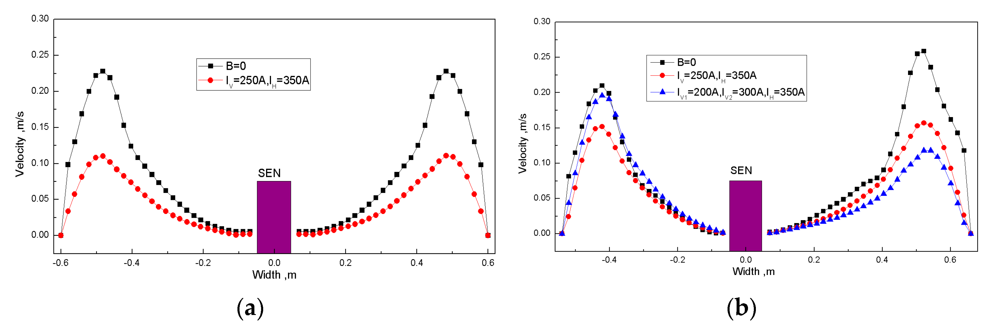
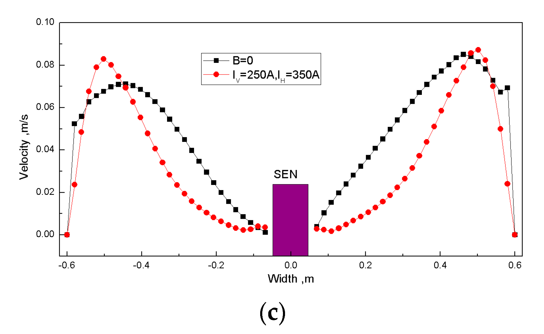
3.2.3. Surface Velocity Distribution

Figure 10a–c show the surface velocity distribution (line y = −0.03 m) for Case 1, Case 2, and Case 3, respectively. As can be seen from Figure 10a, under the condition of Case 1, when the FAC-EMBr is not applied, the maximum velocity on the left and the right sides of the SEN are equal to 0.23 m/s. As FAC-EMBr is applied, the surface velocity decreases obviously, the maximum velocity decreases from 0.23 m/s (No EMBr) to 0.11 m/s(IVP-I = IVP-II = 250 A, IHP = 350 A). It can be seen from Figure 10b that, under the condition of Case 2, when the FAC-EMBr is not applied, the maximum velocity on the left side of the mold is 0.21 m/s and, on the right side, the maximum velocity is 0.26 m/s. After applying the FAC-EMBr, the surface velocity decreases significantly. The maximum surface velocity on the left side decreases from 0.21m/s (No EMBr) to 0.15m/s (IVP-I = IVP-II = 250 A and IHP = 350 A), which decreases by 28.6%. On the right side, the maximum surface velocity decreases from 0.26 m/s (No EMBr) to 0.16 m/s (IVP-I = IVP-II = 250 A and IHP = 350 A), which decreases by 38.5%. Additionally, the difference in the maximum value on both sides is reduced from the 0.05 m/s to 0.01 m/s. In the case of changing VP current, as the left VP current decreases, the maximum velocity on the left increases from 0.15 m/s (IVP-I = IVP-II = 250 A and IHP = 350 A) to 0.2 m/s (IVP-I = 200 A, IVP-II = 300 A, and IHP = 350 A), increasing by 33%. With the decrease and increase in the current of the right VP, the maximum value of the velocity on the right side is reduced from 0.16 m/s (IVP-I = IVP-II = 250 A and IHP = 350 A) to 0.12 m/s (IVP-I = 200 A, IVP-II = 300 A, and IHP = 350 A), which is reduced by 25%. This shows that the VP has an effective brake effect on the surface velocity. It can be seen from Figure 10c that, under the condition of Case 3, when the electromagnetic brake is not applied, the surface velocity distributions on the left and the right of the SEN are asymmetric. The maximum velocities of SEN are 0.07 m/s on the left side and 0.085 m/s on the right side. The maximum velocity on the right side is slightly higher than that on the left side. However, the surface velocity is obviously less than that of Case 1 and Case 2 under the same conditions. With application of FAC-EMBr, the maximum velocity increases slightly, and the maximum velocity on the left and right sides of the nozzle is 0.085 m/s and 0.087 m/s, respectively. This is because the FAC-EMBr improves the asymmetry of jet flow, so that the maximum surface velocity in the z = 0 section increased to a certain extent. However, the surface velocity in the vicinity of the SEN is lower than that without application of EMBr.

4. Conclusions

In this research, a new magnetic field arrangement of FAC-EMBr was introduced to suppress the asymmetric mold flow. The magnetic field, the molten steel flow, and the level fluctuation with asymmetrical SEN (asymmetrical in thickness direction, width direction, and rotating SEN) under the effect of FAC-EMBr were studied using numerical simulations. The main conclusions were as follows:
  • The magnetic field formed by the novel electromagnetic brake can effectively cover three key regions in the mold, namely a molten steel jet flow impact region, an upper recirculation region, and a meniscus region, and the magnetic flux intensity in the covering regions is increased or reduced in sequence along with the change in magnetic pole current;
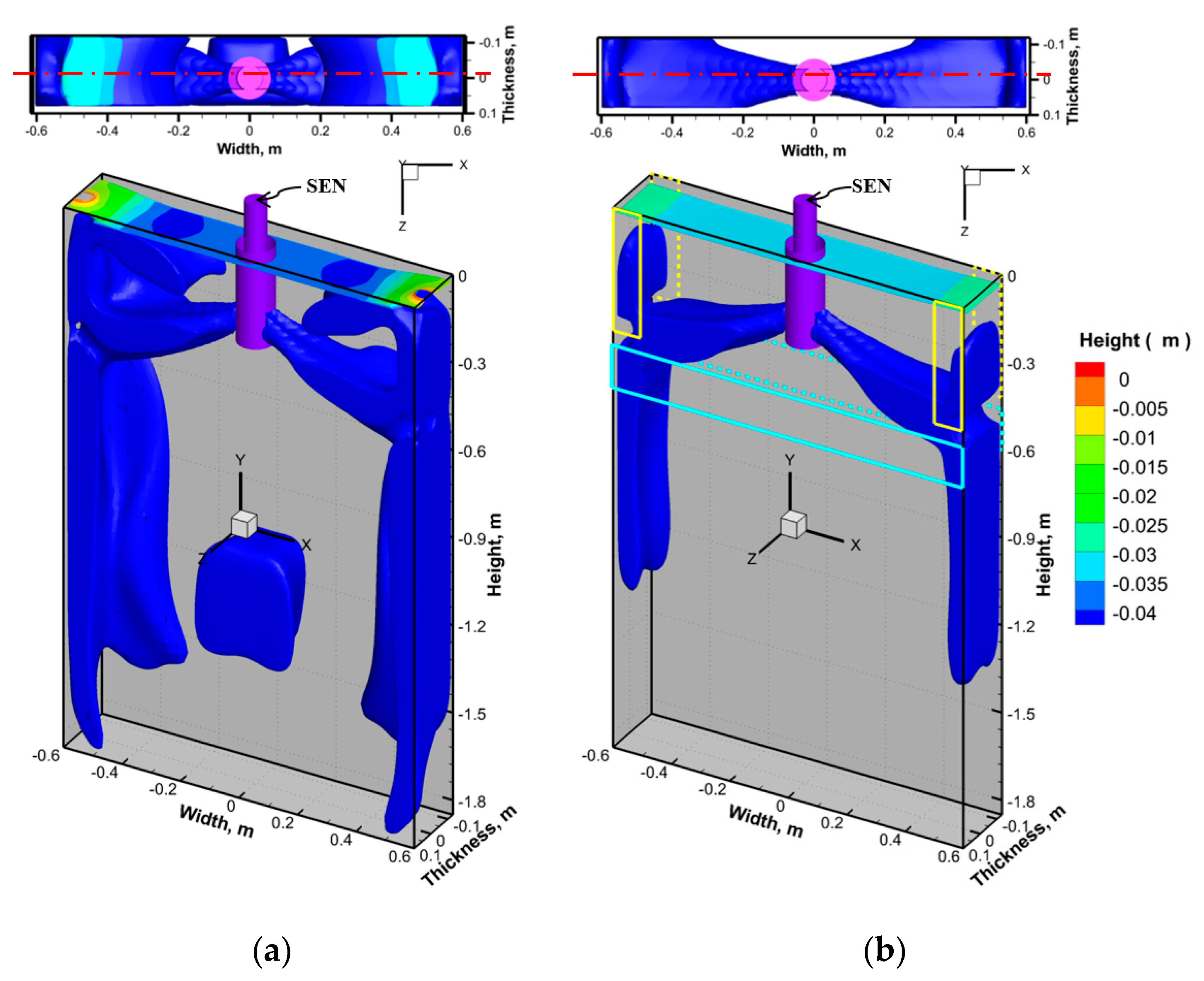
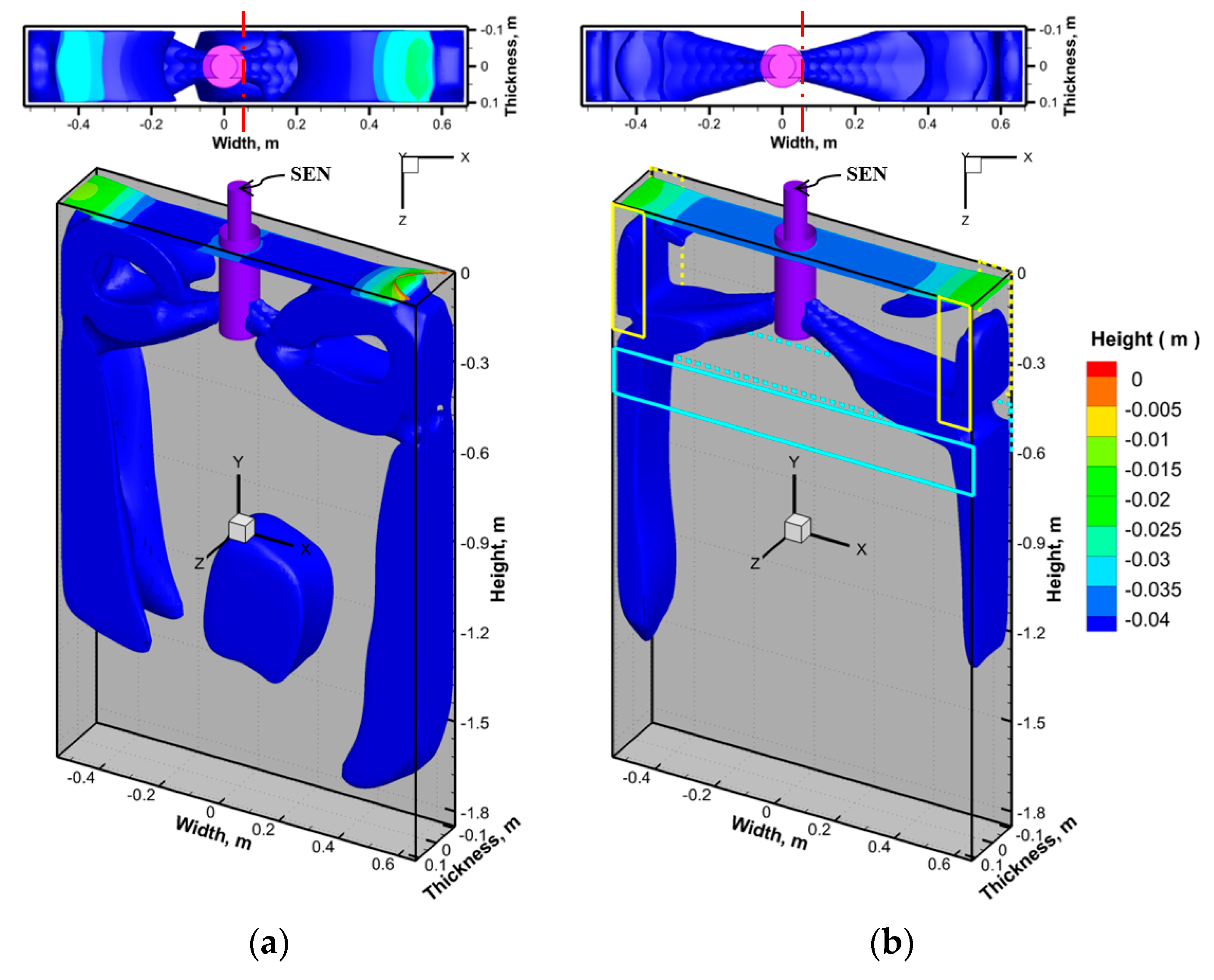
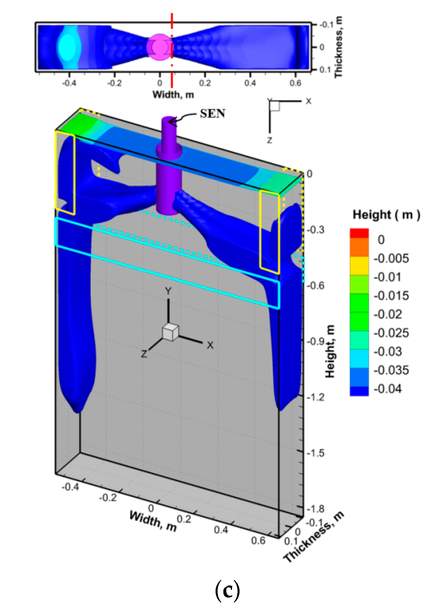
  • The FAC-EMBr can effectively improve the asymmetric flow in the mold and near the narrow face caused by the asymmetric arrangement of the SEN, can reduce the bias flow caused by the asymmetry, and can stabilize the fluctuation of steel/slag interface.
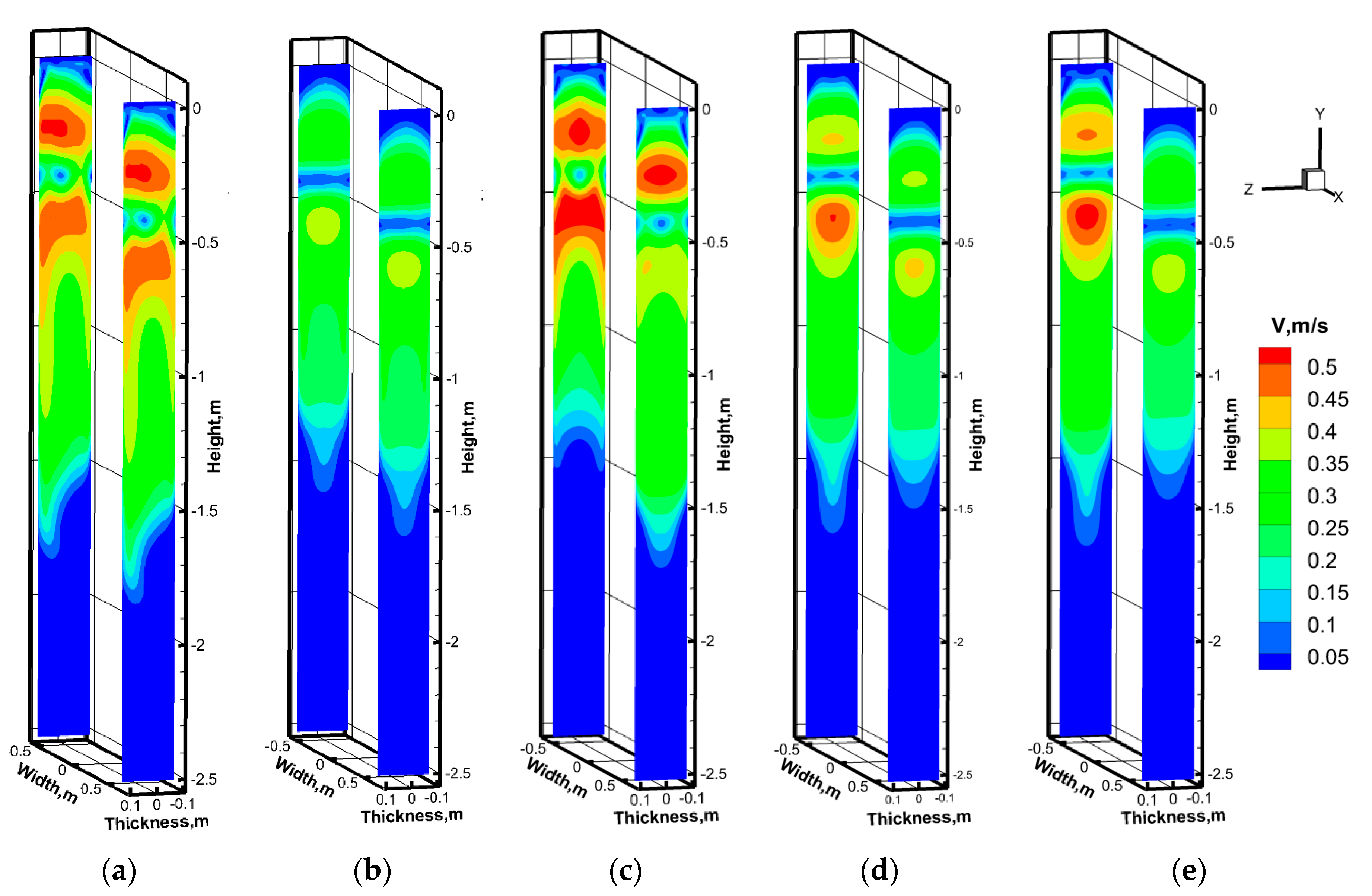
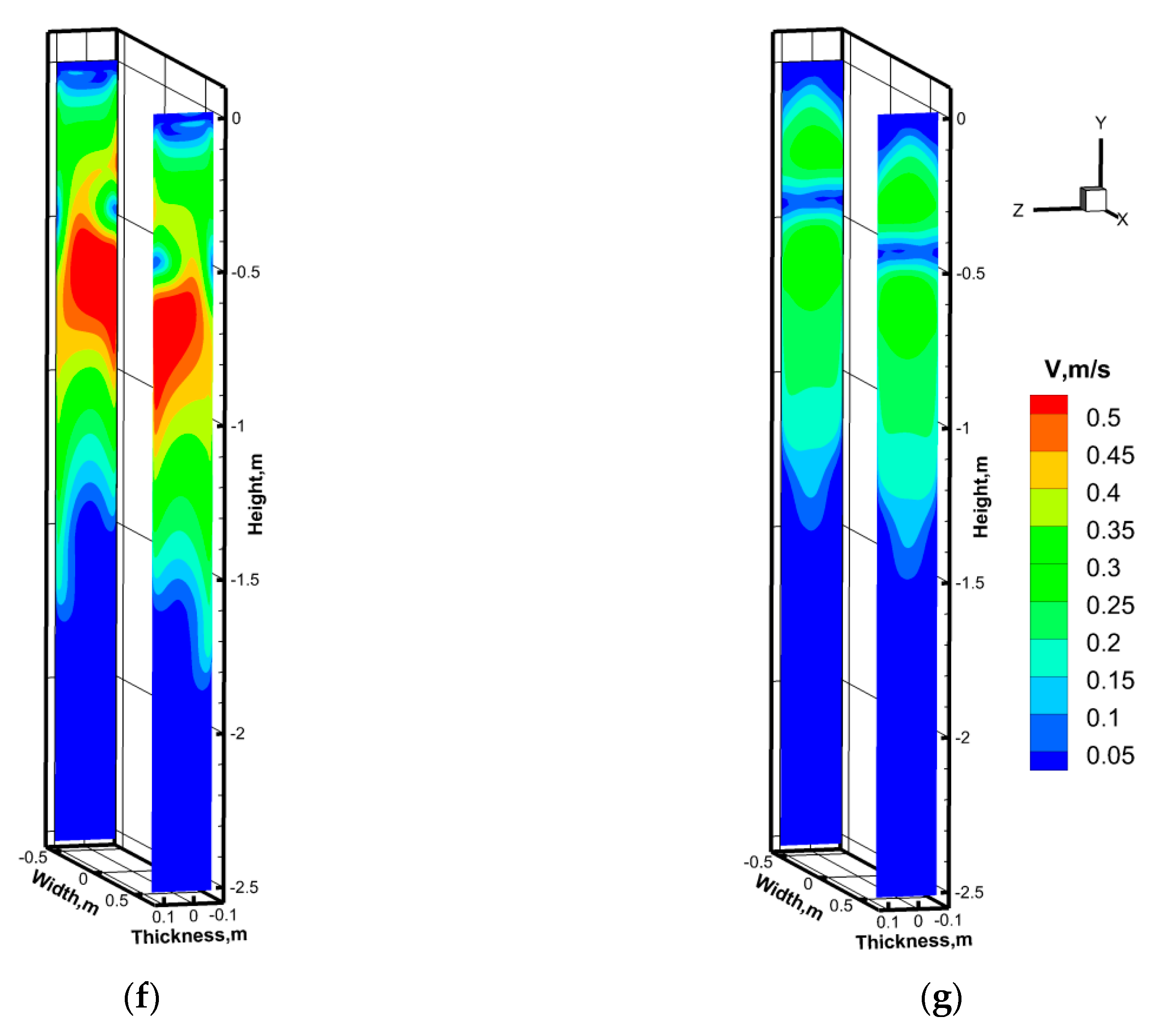
  • The VP has an obvious brake effect on the surface velocity and the upper backflow velocity and can optimize the asymmetric distribution of the surface velocity and the upper recirculation velocity caused by the asymmetric arrangement of the SEN. The HP can obviously restrain the velocity of the lower downwards flow and can optimize the asymmetric distribution of the lower downwards velocity caused by the asymmetric arrangement of SEN.

Author Contributions

Investigation, Y.B., Z.L., J.W. and D.M.; writing—original draft preparation, Z.L., Y.B., L.Z. and F.J.; project administration, Z.L.; and funding acquisition, Z.L. All authors have read and agreed to the published version of the manuscript.

Funding

This research was funded by the National Natural Science Foundation of China, grant number 51804154, and by the College and University Scientific Research Projects in Liaoning Province, grant number L2020023.

Acknowledgments

The authors thank the referees for their work, which greatly contributed to this article.

Conflicts of Interest

The authors declare no conflict of interest.

References

  1. Bai, Y.Q.; Cheng, J.S. Effect of asymmetric flow on slag/steel interface in slab continuous casting cold. China Metall. 2008, 18, 1–6. [Google Scholar]
  2. Xu, H.L.; Wen, G.H.; Tang, P.; Luo, G.Q.; Wang, Y.F. Numerical simulation of asymmetric flow phenomena in slab continuous casting mold. J. Univ. Sci. Technol. 2009, 31, 770–776. [Google Scholar]
  3. Zhang, L.F.; Wang, Y.F.; Zuo, X.J. Flow transport and inclusion motion in steel continuous-casting mold under submerged entry nozzle clogging condition. Metall. Mater. Trans. B 2008, 39, 534–550. [Google Scholar] [CrossRef]
  4. Real-Ramirez, C.A.; Gonzalez-Trejo, J.I. Analysis of three-dimensional vortexes below the free surface in a continuous casting mold. Int. J. Miner. Metall. Mater. 2011, 18, 397–406. [Google Scholar] [CrossRef]
  5. Li, B.; Lu, H.B.; Shen, Z.; Sun, X.H.; Zhon, Y.B.; Ren, Z.M.; Lei, Z.S. Physical modeling of asymmetrical flow in slab continuous casting mold due to submerged entry nozzle clogging with the effect of electromagnetic stirring. ISIJ Int. 2019, 59, 2264–2271. [Google Scholar] [CrossRef] [Green Version]
  6. Wang, Z.G.; Zhang, X.W.; Wang, Y.; Wang, M.; Deng, K.; Ren, Z.M. Effects of Operating Conditions on Asymmetric Vortex in Continuous Casting of Slab. Chin. J. Process Eng. 2010, 10, 438–444. [Google Scholar]
  7. Wu, H.F.; Chen, Z.P.; Wen, G.H.; Xu, H. Influence of nozzle clogging on the behavior of molten steel in slab mold. Iron Steel 2009, 44, 42–47. [Google Scholar]
  8. He, Q.L. Observations slab caster of vortex formation in the mould of a continuous slab caster. ISIJ Int. 1993, 33, 343–345. [Google Scholar] [CrossRef]
  9. Gupta, D.; Lahiri, A.K.A. Water model study of the flow asymmetry inside a continuous slab casting mold. Metall. Mater. Trans. B 1996, 27, 757–764. [Google Scholar] [CrossRef]
  10. Miki, Y.; Takeuchi, S. Internal defects of continuous casting slabs caused by asymmetric unbalanced steel flow in mold. ISIJ Int. 2003, 43, 1548–1555. [Google Scholar] [CrossRef] [Green Version]
  11. Li, B.K.; Tsukihashi, F. Effect of electromagnetic brake on mould eddy current in thin slab continuous casting. Angang Technol. 2009, 2, 51–56. [Google Scholar]
  12. Li, B.K.; Okane, T.; Umeda, T. Modeling of biased flow phenomena associated with the effects of static magnetic-field application and argon gas injection in slab continuous casting of steel. Metall. Mater. Trans. B 2001, 32, 1053–1066. [Google Scholar] [CrossRef]
  13. Chaudhary, R.; Thomas, B.G.; Vanka, S.P. Effect of electromagnetic ruler braking (EMBr) on transient turbulent flow in continuous slab casting using large eddy simulations. Metall. Mater. Trans. B 2012, 43, 532–553. [Google Scholar] [CrossRef]
  14. Sedén, M.; Jacobson, N.; Lehman, A.; Eriksson, J.K. Control of flow behavior by FC mold G3 in slab casting process. In Proceedings of the 8th European Continuous Casting Conference, Graz, Austria, 23–26 June 2014. [Google Scholar]
  15. Kunstreich, S.; Gautreau, T.; Ren, J.Y.; Codutti, A.; Petronio, M. Development and Validation of Multi-Mode® EMB, a New Electromagnetic Brake for Thin Slab Casters. In Proceedings of the 8th European Continuous Casting Conference, Graz, Austria, 23–26 June 2014. [Google Scholar]
  16. Wang, Y.; Zhang, Z.Q.; Yu, Z.; Jia, H.; Deng, K.; Lei, Z.S.; Ren, Z.M. Experimental study on flow in slab mold controlled by jet-pattern magnetic field. Acta Metall. Sin. 2011, 10, 1285–1291. [Google Scholar]
  17. Li, Z.; Zhang, L.T.; Ma, D.Z.; Lavery, N.P.; Wang, E.G. A narrative review: The electromagnetic field arrangement and the “braking” effect of electromagnetic brake (EMBr) technique in slab continuous casting. Metall. Res. Technol. 2021, 118, 218. [Google Scholar] [CrossRef]
  18. Cho, S.M.; Lee, G.G.; Kim, S.H.; Chaudhary, R.; Kwon, O.D.; Thomas, B.G. Effect of stopper-rod misalignment on asymmetric flow and vortex formation in steel slab casting. In Jim Evans Honorary Symposium; Wiley: Hoboken, NJ, USA, 2010; pp. 71–77. [Google Scholar]
  19. Liu, Z.Q.; Li, B.K.; Jiang, M.F. Transient asymmetric flow and bubble transport inside a slab continuous-casting mold. Metall. Mater. Trans. B 2014, 45, 675–697. [Google Scholar] [CrossRef]
  20. Liu, Z.Q.; Li, B.K.; Tsukihashi, F. Instability and periodicity of asymmetrical flow in a funnel thin slab continuous casting mold. ISIJ Int. 2015, 55, 805–813. [Google Scholar] [CrossRef] [Green Version]
  21. Xu, J.G.; Liu, H.P.; Xiang, L.; Chou, S.T. Numerical Simulation of the Effect of Electromagnetic Brake on the Casting Start of CSP Funnel Mold. Iron Steel. 2014, 49, 28–33. [Google Scholar]
  22. Li, Z.; Zhang, L.T.; Ma, D.Z.; Wang, E.G. Numerical simulation on flow characteristic of molten steel in the mold with freestanding adjustable combination electromagnetic brake. Metall. Mater. Trans. B 2020, 51, 2609–2627. [Google Scholar] [CrossRef]
  23. Li, Z.; Zhang, L.T.; Bao, Y.M.; Ma, D.Z. Numerical simulation on the brake effect of FAC-EMBr and EMBr Ruler in the continuous casting mold. Processes 2020, 8, 1620. [Google Scholar] [CrossRef]
  24. Li, Z.; Wang, E.G.; Zhang, L.T.; Zhang, Y.X.; Deng, A.Y. Influence of vertical electromagnetic brake on the steel/slag interface behavior in a slab mold. Metall. Mater. Trans. B 2017, 48, 2389–2402. [Google Scholar] [CrossRef]
Figure 1. Magnetic field arrangement of FAC-EMBr (the current and position of VP can be adjusted according to the actual flow state of molten steel).
Processes 09 01988 g001
Figure 2. Schematic diagram of SEN position. (a) Front view; (b) top view. Case 1: offset to wide face; Case 2: offset to narrow face; and Case 3: SEN rotation.
Processes 09 01988 g002
Figure 3. Geometric dimensions of the fluid region and FAC-EMBr pole.
Processes 09 01988 g003
Figure 4. Three views of the mesh in the fluid region.
Processes 09 01988 g004
Figure 5. Distribution of magnetic flux intensity vector and contour. (a) Case 2, IVP-II; = IVP-II = 250 A and IHP = 350 A; (b) Case 2, IVP-I = 200 A, IVP-II = 300 A, and IHP = 350 A.
Processes 09 01988 g005
Figure 6. Distribution of velocity isosurface (Vsteel = 0.2 m/s) and steel/slag interface under Case 1. (a) IVP-I = IVP-II = IHP = 0 A; (b) IVP-I = IVP-II = 250 A and IHP = 350 A.
Processes 09 01988 g006
Figure 7. Isosurface of molten steel velocity (Vsteel = 0.2 m/s) and steel/slag interface under Case 2. (a) IVP-I = IVP-II = IHP = 0 A; (b) IVP-I = IVP-II = 250 A and IHP = 350 A; and (c) IVP-I = 200 A, IVP-II = 300 A, and IHP=350 A.
Processes 09 01988 g007aProcesses 09 01988 g007b
Figure 8. Isosurface diagram of molten steel velocity (Vsteel = 0.2 m/s) and distribution of magnetic fluxintensity under Case 3. (a) IVP-I = IVP-II = IHP = 0 A; (b) IVP-I = IVP-II = 250 A and IHP = 350 A.
Processes 09 01988 g008
Figure 9. Velocitynephogram of molten steel in x = ±0.595 m section. (a) Case 1, IVP-I = I VP-II = IHP = 0 A; (b) Case 1, IVP-I = IVP-II = 250 A and IHP = 350 A; (c) Case 2, IVP-I = I VP-II = IHP = 0 A; (d) Case 2, IVP-I = IVP-II = 250 A and IHP = 350 A; (e) Case 2, IVP-I = 200 A, IVP-II = 300 A, and IHP = 350 A; (f) Case 3, IVP-I = IVP-II = IHP = 0 A; and (g) Case 3, IVP-I = I VP-II = 250 A and IHP = 350 A.
Processes 09 01988 g009aProcesses 09 01988 g009b
Figure 10. Flow velocity distribution on molten steel surfaces (y = −0.03 m). (a) Case 1,(b) Case 2, and (c) Case 3.
Processes 09 01988 g010aProcesses 09 01988 g010b
Table 1. Material properties and parameters in the simulations.
NameValues
Steel density ρ, kg m s−17100
Slag density ρ, kg m s−12700
Dynamic viscosity μsteel, kg m−1 s−10.006
Dynamic viscosity μslag, kg m−1 s−10.2
Electrical conductivity σsteel, S m−17.14 × 10⁵
Electrical conductivity σslag, S m−11 × 10−5
Current I, A(IVP-Ⅰ = IVP-Ⅱ = IHP=0), (IVP-Ⅰ = IVP-Ⅱ = 250, IHP = 350),
(IVP-Ⅰ = 200, IVP-Ⅱ = 300, IHP = 350)
VP-Ⅰ: VP-I current intensity; IVP-Ⅱ: VP-Ⅱ current intensity; IHP: HP current intensity.
Publisher’s Note: MDPI stays neutral with regard to jurisdictional claims in published maps and institutional affiliations.

