
Convective Heat Transfer Motivated by Liquid-to-Vapor Density Difference in Centrifugal Force Field of Axially Rotating Loop Thermosyphons


Abstract
:
1. Introduction
1.1. Concentric Rotating Heat Pipe
1.2. Radial Rotating Heat Pipe
1.3. Axial Rotating Heat Pipe
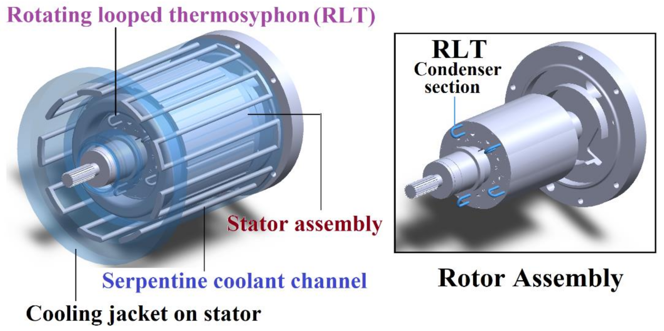
1.4. Thermal Management of Electric Machinery
2. Experimental Method
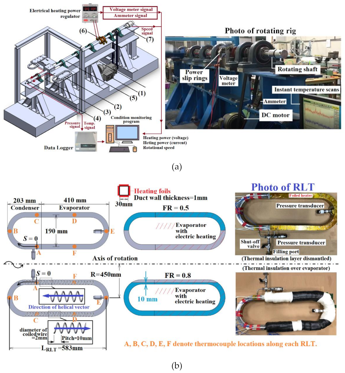
2.1. Experimental Facilities
2.2. Data Processing and Experimental Program
3. Results and Discussion
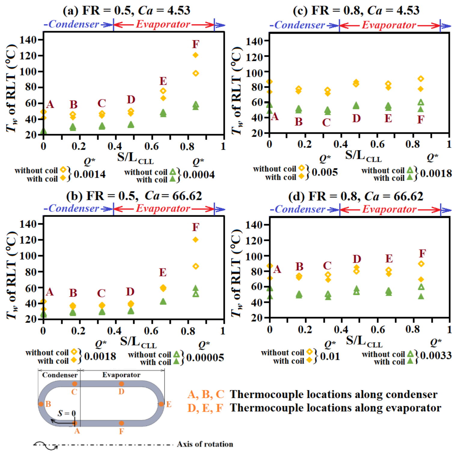
3.1. Operating Conditions with Characteristic Tw Distribution of RLT
3.2. Nusselt Numbers in Evaporator and Condenser
3.3. External Airflow Nusselt Numbers of Rotating Condenser Bend
3.4. Effective Thermal Conductivity of RLT
3.5. Thermal Resistance of RLT
4. Conclusions
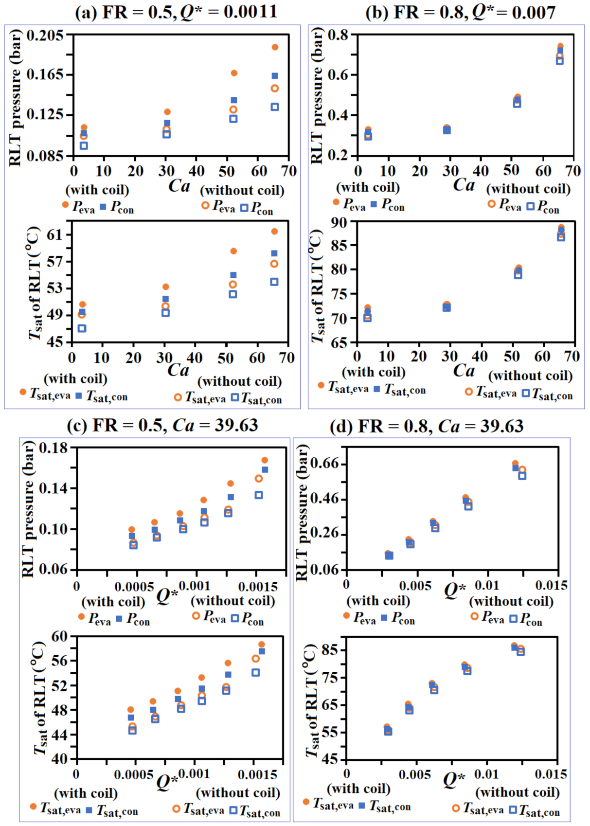
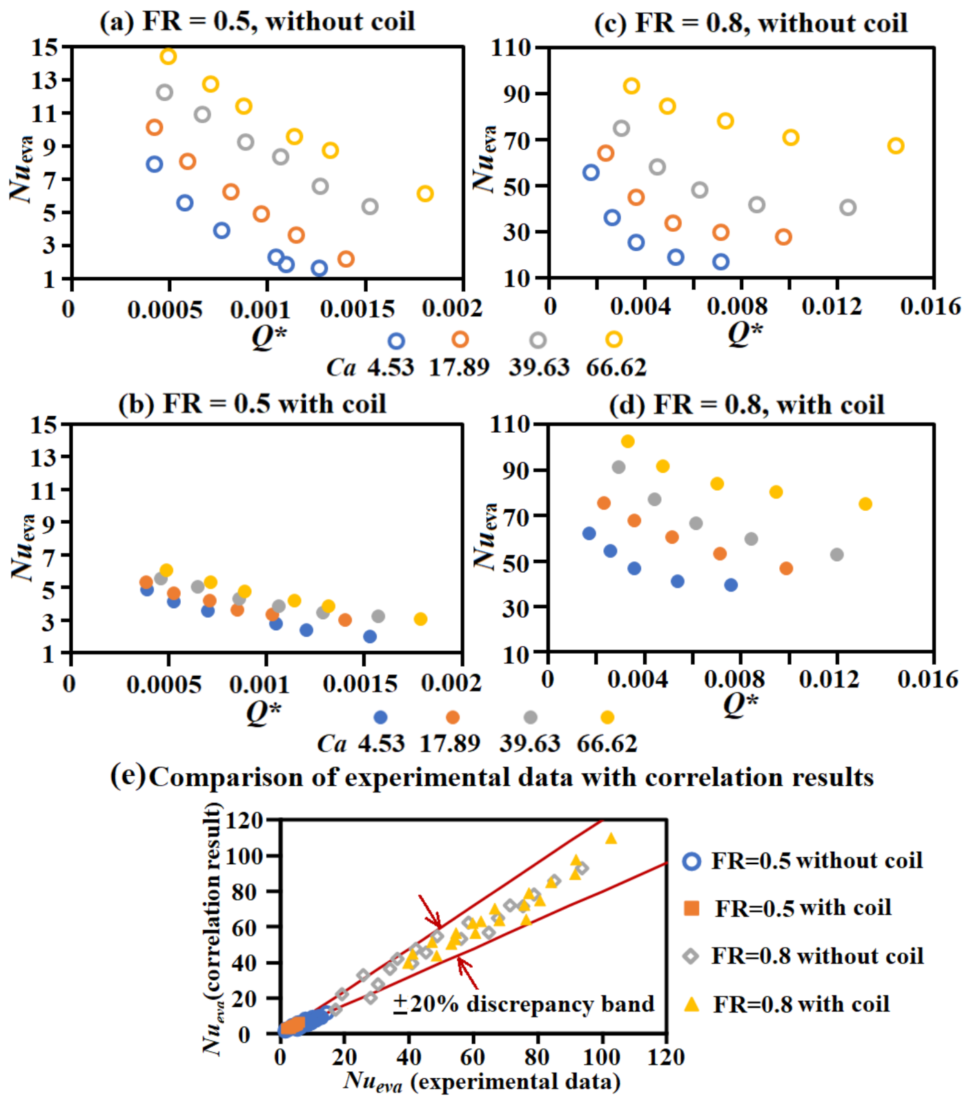
- The pool boiling activities in the outer leg of evaporator were, respectively, converted to the superheated and saturated film boiling processes along the inner leg of the RLTs with FR = 0.5 and 0.8. For all the RLTs tested, Nueva were decreased with Q* but increased with Ca due to the attendant increases of evaporator pressure and Tsat,eva with the improved vapor–liquid circulation when Ca was increased.
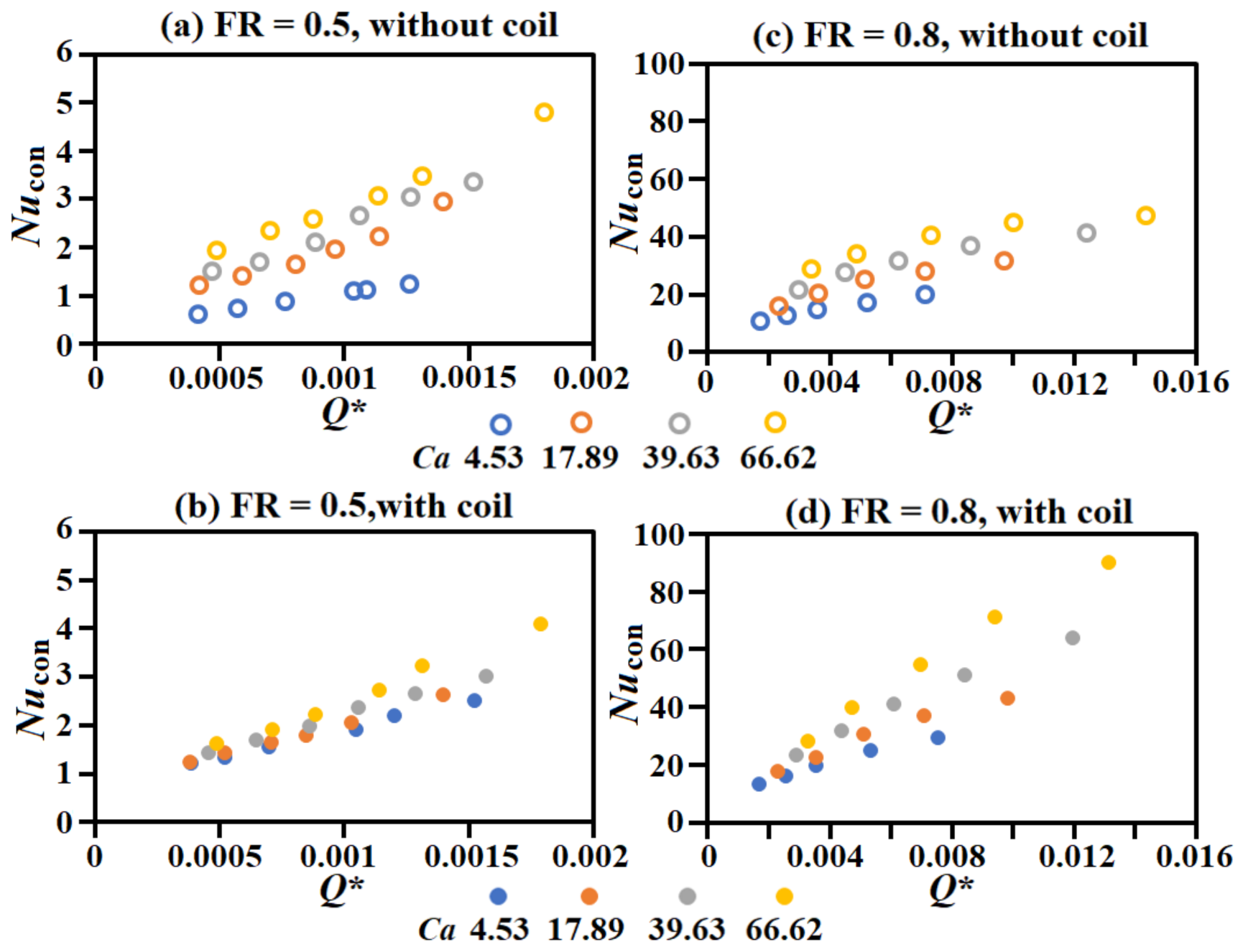
- As the pressure and, hence, Tsat,con were increased by raising Q* and/or Ca, whereas the vapor–liquid segregation force in the condenser was amplified by increasing Ca, all the Nucon data were increased with Q* and Ca.
- The raised airflow velocity surrounding the external surfaces of condenser by increasing Ca incurred the power-law-like Nuext,con increases, regardless Q*, FR, and the coil insert in the RLT.
- With a liquid film in the inner leg of evaporator, by increasing FR from 0.5 to 0.8 to convert the local heating process from superheated to saturated state, all the thermal performance indexes, namely Nueva, Nucon, Nuext,con, Keff, and Rth, were significantly improved. The pumping effect of the coil in the inner leg of the RLT with a filling ratio of 0.8 improved the thermal performance from that without coil. In the inner leg of the RLT with a filling ratio of 0.5, the diminished liquid film prohibited the beneficial pumping effect of the coil but added vapor flow resistance to undermine the thermal performance.
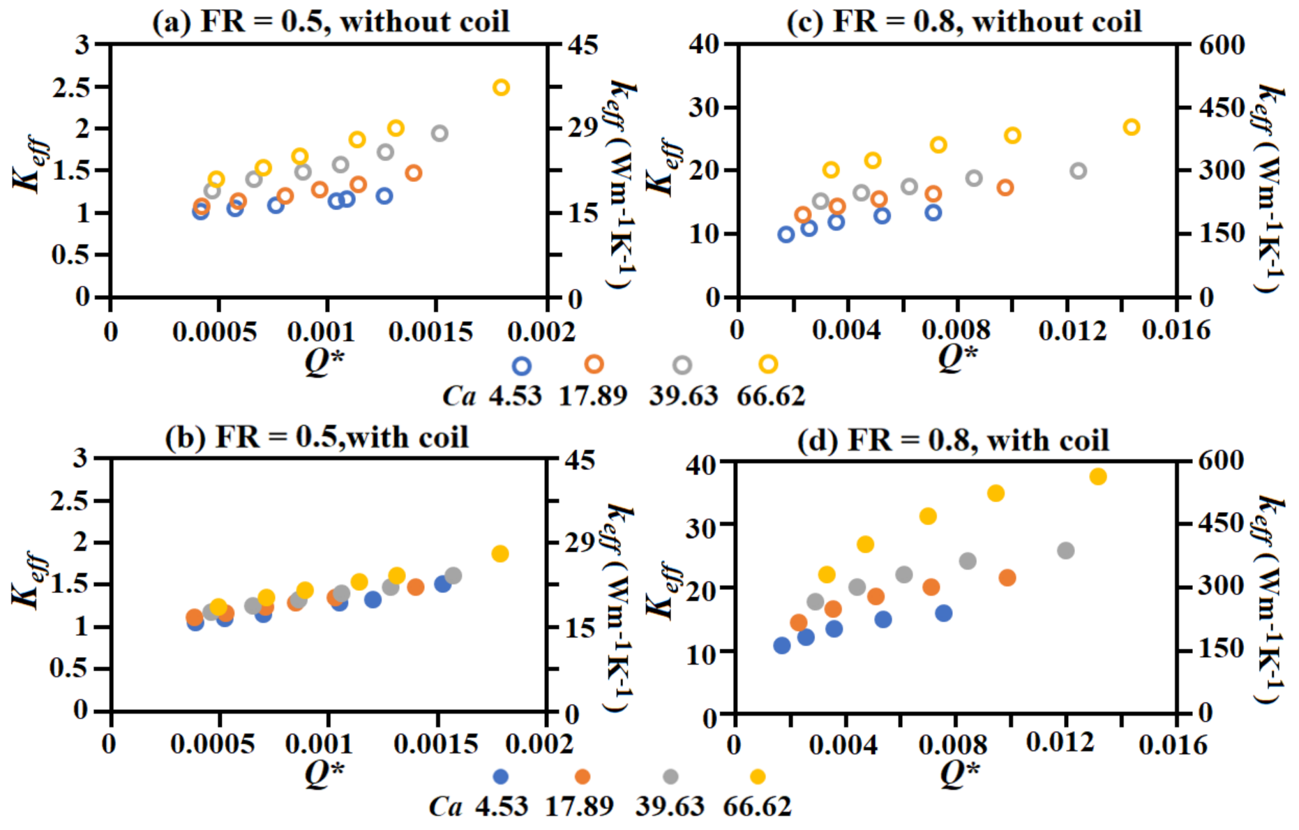
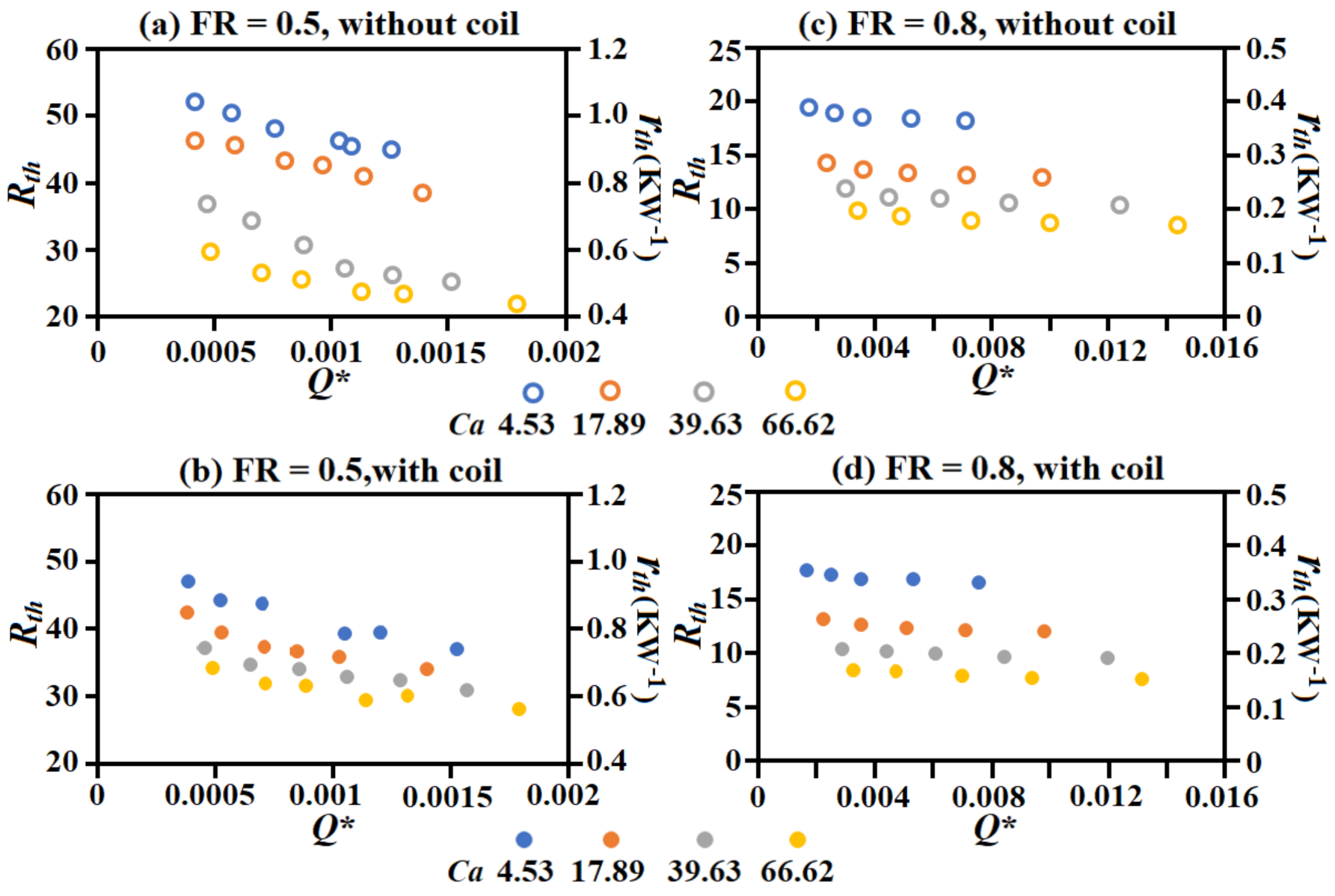
- Acting through the competing Q* effects on Nueva and Nucon, the Keff (Rth) were increased (decreased) with Q*. The increases of Nueva and Nucon with Ca had led to the consistent increase (decrease) of Keff (Rth) by increasing the Ca value. The Keff (1/Rth) followed the order of RLT with coil at FR = 0.8, RLT without coil at FR = 0.5, RLT without coil at FR = 0.5, and RLT with coil at FR = 0.5.
- For the RLT at FR = 0.8 with coil, the effective thermal conductivity reached the range of 161.19–562.43 Wm−1K−1 in the present test conditions, which was elevated to 107.5%–375% of the thermal conductivity of the RLT wall. The corresponding overall thermal resistances of the particular RLT fell in the range of 0.36–0.16 Wm−1K−1.
- The empirical correlations of Nueva, Nucon, Nuext,con, Keff, and Rth were devised to assist the design applications for using the RLT in the rotor of an electric motor.
Author Contributions
Funding
Institutional Review Board Statement
Informed Consent Statement
Data Availability Statement
Conflicts of Interest
Nomenclature
| English symbols | |
| Ca | relative centrifugal acceleration = Ω2R/g |
| d | hydraulic diameter of RLT (m) |
| dc | diameter of coiled wire in RLT (m) |
| g | gravitational acceleration (ms−2) |
| hcon | heat transfer rate in condenser = q/(Tsat,con − con) (Wm−2K−1) |
| heva | heat transfer rate in evaporator = q/(eva − Tsat,eva) (Wm−2K−1) |
| hfg | latent heat of working fluid (J/kg) |
| Keff | non-dimensional effective thermal conductivity = keff/kw |
| kair | Thermal conductivity of air (Wm−1K−1) |
| keff | effective thermal conductivity of RLT (Wm−1K−1) |
| kf | thermal conductivity of liquid water (Wm−1K−1) |
| kw | thermal conductivity of RLT duct (Wm−1K−1) |
| kair | thermal conductivity of air (Wm−1K−1) |
| LRLT | nominal length of RLT (m) |
| Nucon | Nusselt number in condenser of RLT = [q/(Tsat,con − con)]d/kf |
| Nueva | Nusselt number in evaporator of RLT [q/(eva − Tsat,eva)]d/kf |
| Q* | dimensionless heat power = (Qd)/(μfhfg) |
| Q | net heat power transferred by RLT (W) |
| R | centerline rotating radius of RLT (m) |
| ReΩ | rotating Reynolds number = ΩR2/ν |
| Rth | non-dimensional thermal resistance of RLT = rth/(kfd) |
| rth | thermal resistance of RLT = [(eva − Tamb)/Q] |
| S | loop-wise coordinate (m) |
| Tamb | ambient temperature (K) |
| Tsat | saturation temperature of working fluid (K) |
| Tw | wall temperature of RLT (K) |
| Greek symbols | |
| μf | dynamic viscosity of liquid water (kgm−1s−1) |
| ν | kinematic viscosity of the air flow (m2s−1) |
| Ω | angular velocity of RLT (s−1) |
| Subscripts | |
| con | condenser of RLT |
| eva | evaporator of RLT |
| ext,con | external condenser surface of RLT |
| Abbreviations | |
| FR | filling ratio |
| RLT | rotating loop thermosyphon |
| RHP | rotating heat pipe |
References
- Li, S.-F.; Liu, Z. Parametric study of rotating heat pipe performance: A review. Renew. Sustain. Energy Rev. 2020, 117, 109482. [Google Scholar] [CrossRef]
- Lee, J.S.; Kim, C.J. Heat transfer and internal flow characteristics of a coil-inserted rotating heat pipe. Int. J. Heat Mass Transf. 2001, 44, 3543–3551. [Google Scholar] [CrossRef]
- Song, F.; Ewing, D.; Ching, C.Y. Fluid flow and heat transfer model for high-speed rotating heat pipes. Int. J. Heat Mass Transf. 2003, 46, 4393–4401. [Google Scholar] [CrossRef]
- Song, F.; Ewing, D.; Ching, C.Y. Experimental investigation on the heat transfer characteristics of axial rotating heat pipes. Int. J. Heat Mass Transf. 2004, 47, 4721–4731. [Google Scholar] [CrossRef]
- Song, F.; Ewing, D.; Ching, C.Y. Heat transfer in the evaporator section of moderate-speed rotating heat pipes. Int. J. Heat Mass Transf. 2008, 51, 1542–1550. [Google Scholar] [CrossRef]
- Bertossi, R.; Guilhem, N.; Ayel, V.; Romestant, C.; Bertin, Y. Modeling of heat and mass transfer in the liquid film of rotating heat pipes. Int. J. Therm. Sci. 2012, 52, 40–49. [Google Scholar] [CrossRef]
- Xie, M.; Xue, Z.; Qu, W.; Li, W. Experimental investigation of heat transfer performance of rotating heat pipe. Procedia Eng. 2015, 99, 746–751. [Google Scholar] [CrossRef] [Green Version]
- Lian, W.; Chang, W.; Xuan, Y. Numerical investigation on flow and thermal features of a rotating heat pipe. Appl. Therm. Eng. 2016, 101, 92–100. [Google Scholar] [CrossRef]
- Chen, J.; Fu, Y.; Gu, Z.; Shen, H.; He, Q. Study on heat transfer of a rotating heat pipe cooling system in dry abrasive-milling. Appl. Therm. Eng. 2017, 115, 736–743. [Google Scholar] [CrossRef]
- Chatterjee, S.; Sugilal, G.; Prabhu, S.V. Flow transitions in a partially filled rotating inclined pipe with continuous flow. Exp. Therm. Fluid Sci. 2017, 83, 47–56. [Google Scholar] [CrossRef]
- Ling, J.; Cao, Y.; Chang, W.S. Analyses of radially rotating high-temperature heat pipes for turbomachinery applications. Trans. ASME J. Eng. Gas Turbines Power 1999, 121, 306–312. [Google Scholar] [CrossRef]
- Ling, J.; Cao, Y. Closed-form analytical solutions for radially rotating miniature high-temperature heat pipes including non-condensable gas effects. Int. J. Heat Mass Transf. 2000, 43, 3661–3671. [Google Scholar] [CrossRef]
- Ling, J.; Cao, Y.; Lopez, A.P. Experimental investigations of radially rotating miniature high-temperature heat pipes. Trans. ASME J. Heat Transf. 2001, 123, 113–119. [Google Scholar] [CrossRef]
- Waowaew, N.; Terdtoon, P.; Maezawa, S.; Kamonpet, P.; Klongpanich, W. Correlation to predict heat transfer characteristics of a radially rotating heat pipe at vertical position. Appl. Therm. Eng. 2003, 23, 1019–1032. [Google Scholar] [CrossRef]
- Aboutalebi, M.; Moghaddam, A.M.N.; Mohammadi, N.; Shafii, M.B. Experimental investigation on performance of a rotating closed loop pulsating heat pipe. Int. Commun. Heat Mass Transf. 2013, 45, 137–145. [Google Scholar] [CrossRef]
- Li, Y.; Li, Z.; Chen, C.; Yan, Y.; Zeng, Z.; Li, B. Thermal responses of heat pipes with different wick structures under variable centrifugal accelerations. Appl. Therm. Eng. 2016, 96, 352–363. [Google Scholar] [CrossRef]
- Chen, J.; Fu, Y.; He, Q.; Shen, H.; Ching, C.Y.; Ewing, D. Environmentally friendly machining with a revolving heat pipe grinding wheel. Appl. Therm. Eng. 2016, 107, 719–727. [Google Scholar] [CrossRef]
- Chang, S.W.; Cai, W.L. Thermal performance of two-phase thermosyphon loop in rotating thin pad. Int. J. Therm. Sci. 2017, 112, 270–288. [Google Scholar] [CrossRef]
- On-ai, K.; Kammuang-lue, N.; Terdtoon, P.; Sakulchangsatjatai, P. Implied physical phenomena of rotating closed-loop pulsating heat pipe from working fluid temperature. Appl. Therm. Eng. 2019, 148, 1303–1309. [Google Scholar] [CrossRef]
- Liou, T.-M.; Chang, S.W.; Cai, W.L.; Lan, I.-A. Thermal fluid characteristics of pulsating heat pipe in radially rotating thin pad. Int. J. Heat Mass Transf. 2019, 131, 273–290. [Google Scholar] [CrossRef]
- Faghri, A.; Gogineni, S.; Thomas, S. Vapor flow analysis of an axially rotating heat pipe. Int. J. Heat Mass Transf. 1993, 36, 2293–2303. [Google Scholar] [CrossRef]
- Jankowski, T.A.; Prenger, F.C.; Razani, A. Experimental study of a curved rotating heat pipe. Trans. ASME J. Heat Transf. 2008, 130, 101601. [Google Scholar] [CrossRef]
- Yau, Y.H.; Foo, Y.C. Comparative study on evaporator heat transfer characteristics of revolving heat pipes filled with R134a, R22 and R410A. Int. Commun. Heat Mass Transf. 2011, 38, 202–211. [Google Scholar] [CrossRef]
- Hassan, H.; Harmand, S. An experimental work on the effect of the radius of rotation on the performance of revolving heat pipe (RVHP). Appl. Therm. Eng. 2017, 123, 537–545. [Google Scholar] [CrossRef]
- Gundabattini, E.; Mystkowski, A.; Idzkowski, A.; Singh, R.; Solomon, D.G. Thermal mapping of a high-speed electric motor used for traction applications and analysis of various cooling methods-a review. Energies 2021, 14, 1472. [Google Scholar] [CrossRef]
- Deisenroth, D.C.; Ohadi, M. Thermal management of high-power density electric motors for electrification of aviation and beyond. Energies 2019, 12, 3594. [Google Scholar] [CrossRef] [Green Version]
- Canders, W.-R.; Hoffmann, J.; Henke, M. Cooling technologies for high power density electrical machines for aviation applications. Energies 2019, 12, 4579. [Google Scholar] [CrossRef] [Green Version]
- Guo, F.; Zhang, C. Oil-cooling method of the permanent magnet synchronous motor for electric vehicle. Energies 2019, 12, 2984. [Google Scholar] [CrossRef] [Green Version]
- Fujita, H.; Itoh, A.; Urano, T. Newly developed motor cooling method using refrigerant. World Electr. Veh. 2019, 10, 38. [Google Scholar] [CrossRef] [Green Version]
- Wu, P.-S.; Hsieh, M.-F.; Cai, W.L.; Liu, J.-H.; Huang, Y.-T.; Caceres, J.F.; Chang, S.W. Heat transfer and thermal management of interior permanent magnet synchronous electric motor. Inventions 2019, 4, 69. [Google Scholar] [CrossRef] [Green Version]
- Kline, S.J.; McClintock, F.A. Describing uncertainties in single sample experiments. Mech. Eng. 1953, 75, 3–8. [Google Scholar]


| Instrument | Precision | Data Range | Max. Error (%) |
|---|---|---|---|
| Voltage meter | 0.01 V | 32.92–131.25 V | 0.03 |
| Ammeter | 0.01 A | 1.35–5.56 A | 0.74 |
| Pressure gauge | 0.0001 bar | 0.0767–0.7381 bar | 0.13 |
| Rotating speed detector | 0.1 rpm | 100–400 rpm | 0.1 |
| Thermocouple | 0.3 K | Tamb 298–300 K | 1.2 |
| Tw,eva 312.8–362.7 K | 0.75 | ||
| Tw,con 313.2–392.8 | 0.75 | ||
| Tw,ext.con 311.8–361.6 | 0.77 |
| Ca | FR = 0.5 | FR = 0.8 | ||||||
|---|---|---|---|---|---|---|---|---|
| Without Coil | With Coil | Without Coil | With Coil | |||||
| a | b | a | b | a | b | a | b | |
| 4.53 | −5.81 | −37.53 | −1.67 | −8.59 | −27.22 | −122.33 | −15.82 | −39.99 |
| 17.89 | −5.9 | −36.03 | −1.86 | −9.34 | −25.6 | −95.5 | −19.32 | −41.45 |
| 39.63 | −6.12 | −34.07 | −1.98 | −9.63 | −24.69 | −72.67 | −26.8 | −67.16 |
| 66.62 | −6.34 | −33.49 | −2.33 | −11.61 | −18.31 | −11.62 | −33 | −78.08 |
| Ca | FR = 0.5 | FR = 0.8 | |||||||
|---|---|---|---|---|---|---|---|---|---|
| Without Coil | With Coil | Without Coil | With Coil | ||||||
| m | n | m | n | m | n | m | n | ||
| 4.53 | 164.58 | 0.65 | 83.65 | 0.55 | 320 | 0.55 | 459.25 | 0.56 | |
| 17.89 | 295.97 | 0.7 | 105.86 | 0.57 | 316.43 | 0.49 | 844.83 | 0.64 | |
| 39.63 | 415.5 | 0.74 | 169.88 | 0.63 | 313.88 | 0.46 | 1598.9 | 0.72 | |
| 66.62 | 502 | 0.77 | 428.53 | 0.74 | 221.84 | 0.35 | 3651.9 | 0.85 | |
| Ca | FR = 0.5 | FR = 0.8 | ||||||
|---|---|---|---|---|---|---|---|---|
| Without Coil | With Coil | Without Coil | With Coil | |||||
| f | g | f | g | f | g | f | g | |
| 4.53 | 26.43 | 101,715 | 101.41 | 148,494 | 39.98 | 0.236 | 59.664 | 0.282 |
| 17.89 | 195.55 | 85,634 | 295.06 | 30,524 | 44.83 | 0.217 | 77.74 | 0.286 |
| 39.63 | 497.11 | 66,957 | 356.58 | 13,998 | 47.19 | 0.207 | 101.54 | 0.312 |
| 66.62 | 704.4 | 60,612 | 461.58 | 8906 | 62.05 | 0.205 | 194.46 | 0.38 |
| Ca | FR = 0.5 | FR = 0.8 | ||||||
|---|---|---|---|---|---|---|---|---|
| Without Coil | With Coil | Without Coil | With Coil | |||||
| i | j | i | j | i | j | i | j | |
| 4.53 | 17.53 | −0.141 | 12.36 | −0.17 | 14.47 | −0.046 | 14.345 | −0.041 |
| 17.89 | 15.04 | −0.147 | 11.26 | −0.168 | 9.32 | −0.069 | 9.257 | −0.062 |
| 39.63 | 8.67 | −0.179 | 11.14 | −0.157 | 6.85 | −0.092 | 7.498 | −0.063 |
| 66.62 | 5.02 | −0.231 | 11.04 | −0.149 | 5.61 | −0.096 | 5.645 | −0.079 |
Publisher’s Note: MDPI stays neutral with regard to jurisdictional claims in published maps and institutional affiliations. |
© 2021 by the authors. Licensee MDPI, Basel, Switzerland. This article is an open access article distributed under the terms and conditions of the Creative Commons Attribution (CC BY) license (https://creativecommons.org/licenses/by/4.0/).
Share and Cite
Chang, S.W.; Hsieh, M.-F.; Wu, P.-S.; Cai, W.L. Convective Heat Transfer Motivated by Liquid-to-Vapor Density Difference in Centrifugal Force Field of Axially Rotating Loop Thermosyphons. Processes 2021, 9, 1909. https://doi.org/10.3390/pr9111909
Chang SW, Hsieh M-F, Wu P-S, Cai WL. Convective Heat Transfer Motivated by Liquid-to-Vapor Density Difference in Centrifugal Force Field of Axially Rotating Loop Thermosyphons. Processes. 2021; 9(11):1909. https://doi.org/10.3390/pr9111909
Chicago/Turabian StyleChang, Shyy Woei, Min-Fu Hsieh, Pey-Shey Wu, and Wei Ling Cai. 2021. "Convective Heat Transfer Motivated by Liquid-to-Vapor Density Difference in Centrifugal Force Field of Axially Rotating Loop Thermosyphons" Processes 9, no. 11: 1909. https://doi.org/10.3390/pr9111909
APA StyleChang, S. W., Hsieh, M.-F., Wu, P.-S., & Cai, W. L. (2021). Convective Heat Transfer Motivated by Liquid-to-Vapor Density Difference in Centrifugal Force Field of Axially Rotating Loop Thermosyphons. Processes, 9(11), 1909. https://doi.org/10.3390/pr9111909