Article

Influence of Moulding Pressure on the Burst Pressure of Reverse-Acting Rupture Discs

1
School of Mechatronic Engineering, China University of Mining and Technology, Xuzhou 221116, China
2
Xuzhou Bafang Safety Device Co., Ltd., Xuzhou 221141, China
*
Author to whom correspondence should be addressed.
Processes 2021, 9(10), 1775; https://doi.org/10.3390/pr9101775
Submission received: 10 August 2021 / Revised: 25 September 2021 / Accepted: 29 September 2021 / Published: 4 October 2021
(This article belongs to the Topic Modern Technologies and Manufacturing Systems)

Abstract

:
Rupture discs, also called bursting discs, are widely used in pressure vessels, pressure equipment, and pressure piping in process industries, such as nuclear power, fire protection, and petrochemical industries. To explore the relationship between the burst pressure of reverse-acting rupture discs and their production, two common manufacturing methods, air pressure moulding and hydraulic moulding, were compared in this study. Reverse-acting rupture discs that complied with the form recommended by API 520-2014 were prepared with four release diameters, and burst pressure tests were carried out. These results showed an obvious negative correlation between the forming pressure of rupture discs and their actual burst pressure for all experimental samples. Further study showed that the main reason for this correlation was a reduction in thickness at the top of the rupture disc caused by large plastic deformation during compression moulding. To explore the relationship between the thickness reduction effect and moulding method, this study defined the “relative ratio of thickness reduction” and concluded that the effect of decreasing the thickness of the rupture disc was more obvious for rupture disc substrates with less flexural rigidity. The above conclusions have important significance for guiding the control of the burst pressure of rupture discs.

1. Introduction

Rupture discs are important protective devices used to safeguard pressure vessels and fluid pipelines from overpressure hazards; they have been widely used in major industrial systems and production facilities [1,2,3,4]. Rupture discs and pressure relief valves (PRV) are both overpressure relief devices applied to high-pressure equipment, but the application scenarios of the two are different. The PRV reduces the excessive pressure in the equipment through the automatic opening of the valve to discharge the gas. The device itself can be reused many times, but the pressure relief response is slow. It is suitable for equipment with relatively clean media such as air and water vapor [5]. Rupture discs use blasting elements to break and discharge gas under higher pressure. The sealing performance is good and the pressure relief response is faster. Compared with PRV, rupture discs have the advantages of simple structure, sensitivity, reliability, economy, no leakage, and strong adaptability. In some equipment where the pressure may rise sharply, as well as in the face of high-viscosity slurry fluids or for corrosive fluids, it is more reasonable to use rupture discs as safety devices [6,7]. The rupture disc is a nonerasable component, and its design is simple. The commercial prospects for rupture discs are broad because the manufacturing methods for rupture disks are convenient and rupture discs allow leakage of overpressure media without causing secondary damage [8]. To facilitate practical applications of rupture discs, the typical industrial standard [9,10] emphasizes the pressure limitation of the entire pressure relief system, and most researchers and engineers propose specific indicators of the discharge effect of rupture discs under such rated conditions. For example, some scholars discussed the characteristics of the actual mass flow of a compressible fluid while leaking at the rated pressure [11,12], and some scholars established a new descriptive theory of the venting effect [13] based on the thermodynamic property changes caused by friction and heat exchange. With the development of the hydrogen energy field, the relationship between the bursting effect of rupture discs and the spontaneous combustion probability of high-pressure hydrogen has become a major focus [14,15,16,17,18]. The pressure relief effects of rupture discs have also received more attention for applications related to the thermal protection of batteries [19].
In general, the venting effect of a rupture disc is closely related to the parameter referred to as burst pressure, and many studies have proposed a classic method to calculate the burst pressure of a rupture disc [20,21,22]. With the application of the finite element numerical simulation method in design engineering, great progress has been made to develop calculation models of the burst pressure of rupture discs [23,24]. However, few studies have been performed on the effect of production conditions on the burst pressure of rupture discs. According to the needs of research and testing, researchers usually make a specific type of rupture disc and explore its opening performance [25,26,27] under specific experimental conditions. However, the effects of the methods that are commonly used to make rupture disks in large-scale production, such as pneumatic forming and hydraulic forming, on the thickness of the rupture disc diaphragm, the height and position of its arch and the conditions for the rupture or buckling of the dome to release pressure under operating conditions, are still unclear. There have been few systematic studies on the relationship between the burst pressure of rupture discs or the rupture effects and the production process parameters.
In this study, a rupture disc burst pressure test device was built to conform to the formal test requirements of API Standard 520, and tests were carried out on reverse-acting rupture discs according to pressure and hydraulic modelling methods. The main process parameters for the production of rupture discs were explored, such as the influence of forming pressure, substrate characteristics, and die calibre on the burst pressure of rupture discs. Forward-looking guidance and opinions are given about the influence of the actual production mode of rupture discs on their service performance.

2. Preparation for Experimental Study

2.1. Selection of Design Parameters for Rupture Disc Production

Current studies show that plastic instability is the main reason for a reverse-acting rupture disc to open under external pressure and that fracture failure occurs in the weakest part of its structure [28]. In this study, a cross-shaped groove was carved on the exterior of a reverse-acting rupture disc. When the pressure reached the critical value for failure, the rupture disc developed plastic instability, and the dome inverted. Due to the low structural strength of the cross-shaped groove, the fracture happens at the groove, the rupture disc opens, and the medium with overpressure is released or vented. Figure 1 shows the installation and form of the rupture discs before and after they opened in this experiment.
Based on the summary of previous research by Zhu et al. [22], Equations (1) and (2) were used in this study to select the design parameters and production parameters of the rupture discs.
P b = 4 σ s · 2 3 n · s D n ,
P f σ 0.2 · s D n · 16 H s 1 + 4 H s 2 ,
Equation (1) calculates the burst pressure of the rupture disc. P b is the overpressure load corresponding to the bursting of the rupture disc, σ s is the fracture limit of the rupture disc material, n is the strain hardening exponent of the rupture disc material, s is the thickness of the rupture disc diaphragm, and D n is the venting size of the rupture disc. Equation 2 calculates the recommended pressure to form a rupture disk during production. P f is the recommended pressure for forming a dome structure from a circular plate of base material; σ 0.2 is the yield strength of the rupture disc material; H is the height of the arch of the rupture disc. In this study, laser etching was used to make a cross-shaped groove on the rupture disc. For the production process, the mechanical properties of the rupture disc material, the size of the mould, the power used for laser etching, and the method of applying pressure to form the device were controlled. Figure 2 shows the value of each parameter.

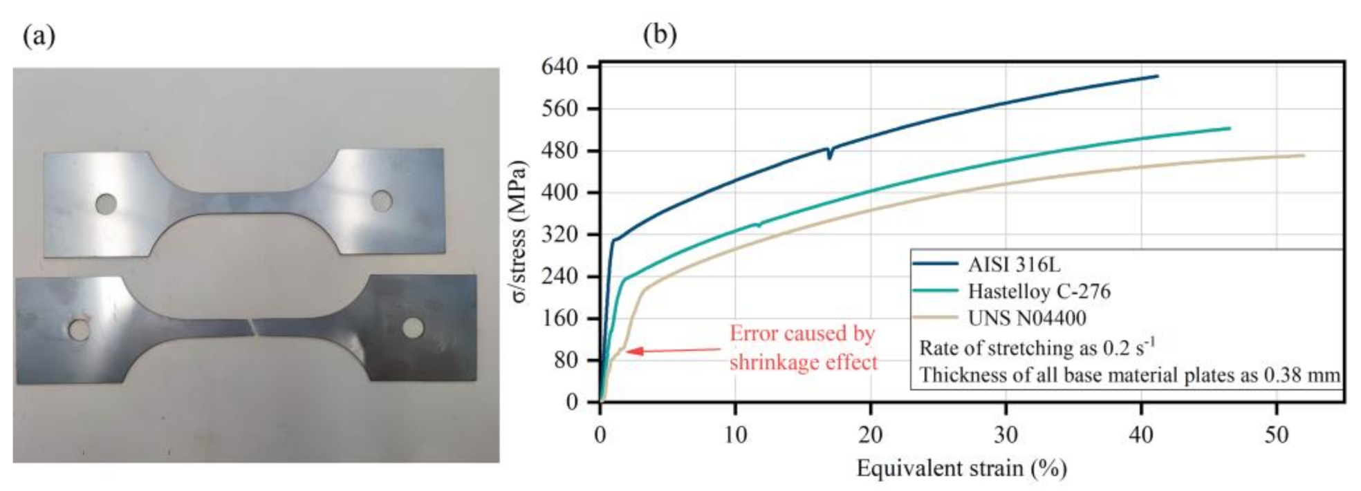
2.2. Tests for the Mechanical Performance of the Base Material

The process parameters for the rupture disc were controlled during production, and the choice of the rupture disc material also determined the performance of the rupture disc. In this study, the tensile test is carried out according to the standard ASTM E8/E8M-16a Standard Test Methods for Tension Testing of Metallic Materials [29], as shown in Figure 3a. Tensile tests were carried out on all rupture disc materials used in the study to evaluate the differences in batches, thicknesses, and heat treatment processes of various rupture disc substrate materials. The yield strength, fracture limit, and strain hardening exponent of each material were obtained according to the method proposed by Liu et al. [30]. Figure 3b shows examples of stress–strain curves for three different materials with a sheet thickness of 0.38 mm.

3. Experimental Studies of Moulding Methods and Burst Pressure

3.1. Moulding Method and Sample Preparation

The method to mould a rupture disc consists of applying external pressure to a round base plate to form a hemispherical shell. The shape of the thin circular plate under compression moulding is not a normative spherical shell [31,32]. However, the deformation pressure on the thin circular plate can be maintained so that it deforms and becomes as similar as possible to the mould. Additionally, rupture disc products are manufactured to be more similar to the shape of a spherical shell [33,34]. Some researchers [24] found that the thickness of the arch in the rupture disc is reduced during compression forming, which is another focus of this research.
Compression moulding uses air or hydraulic oil; these two media behave differently when compressed [35,36]. To explore the influence of the forming medium on the performance of a rupture disc, hydraulic oil and air were compared in this study. Further, the size of the diameter of the forming die and the change in the thickness of the base material not only determine the venting diameter of the rupture disc but also have a certain influence on the formation of the rupture disc [37,38]. Therefore, this study included four die diameters (50 mm, 80 mm, 100 mm, and 150 mm) and three plate thicknesses for each diameter. Table 1 summarizes the modelling parameters and forming methods used to make rupture discs with various arch heights, sheet thicknesses, mould sizes, and forming media. The theoretical forming pressure is calculated by Equation (2) together with the predetermined height of the arch in the mould.

3.2. Forming Equipment and Pressure Loading Method

In the moulding method, the main options are the size of the forming pressure and forming pressure medium. The production equipment used to make the rupture discs in this study is shown in Figure 4. The Forming mould base and rupture discs of different materials are shown in Figure 5. The equipment consisted of three main parts: a clamping device, pressure supply system, and control system. The raw materials used to make the rupture disc were manufactured and moulded into the desired shape. A valve in the pressurization system was used to switch between the different forming media. The pressure of the forming medium was adjusted at its source (oil pump or compressor). The pressure sensor (CYG405, 0–10 MPa, produced by Shuangqiao sensor measurement controlling Co., Ltd., Kunshan, China.) is installed on the inner wall of the intake pipe. The accuracy of the sensor is as follows: zero time drift is 0.1 mv/8h; non-linearity is ±0.2%; zero temperature coefficient is 2 × 10⁻⁴ FS/°C; sensitivity temperature coefficient is 2 × 10⁻⁴ FS/°C. This sensor can be used for various explosion shockwave measurement and dynamic pressure measurement.
To provide enough energy to the forming medium in order to overcome the resistances to forming and flowing in pipelines, the pressure at the source of the forming medium usually exceeded the theoretical recommended pressure required for forming. To make the experimental data more convincing, at least 11 forming pressures were used to produce each type of rupture disc. When the main electric control valve was opened, the forming medium entered the mould, plastically deforming the base material and gradually forming the shape of the rupture disc.
There is a proximity sensor at the upper end of the rupture disc forming mould. When the height of the arch of the rupture disc reaches that of the mould, the proximity sensor automatically signals the control system to record and unload the forming pressure and record the forming pressure of the rupture disc. This method prevented overload of the forming pressure and incomplete processing of the rupture disc. This method ensured that rupture discs were be made under the same mould conditions. In addition, all the rupture discs involved in the experiment were produced in the workshop in accordance with the API 520 standard, and at least 6 replicates were made of each finished product to guarantee a ratio of 5:1 for the experimental study, which effectively avoided the possibility of random defects and errors.
To explore the reduction in the thickness of the arch during the forming of the rupture discs, a spiral micrometre was used to measure the thickness of the arch to obtain the relationship between the reduction in the rupture disc strength and the size of the forming pressure. To ensure the accuracy of the measurement position of the spiral micrometre, the thickness of the top of the arch in each rupture disc was measured at least three times, and the average was calculated. The method ensured that the data obtained with the spiral micrometre were obtained as close as possible to the precise position of the highest point of the arch and ensured the accuracy of the results of this research. The recorded data were used to analyse the experimental data in the next step.

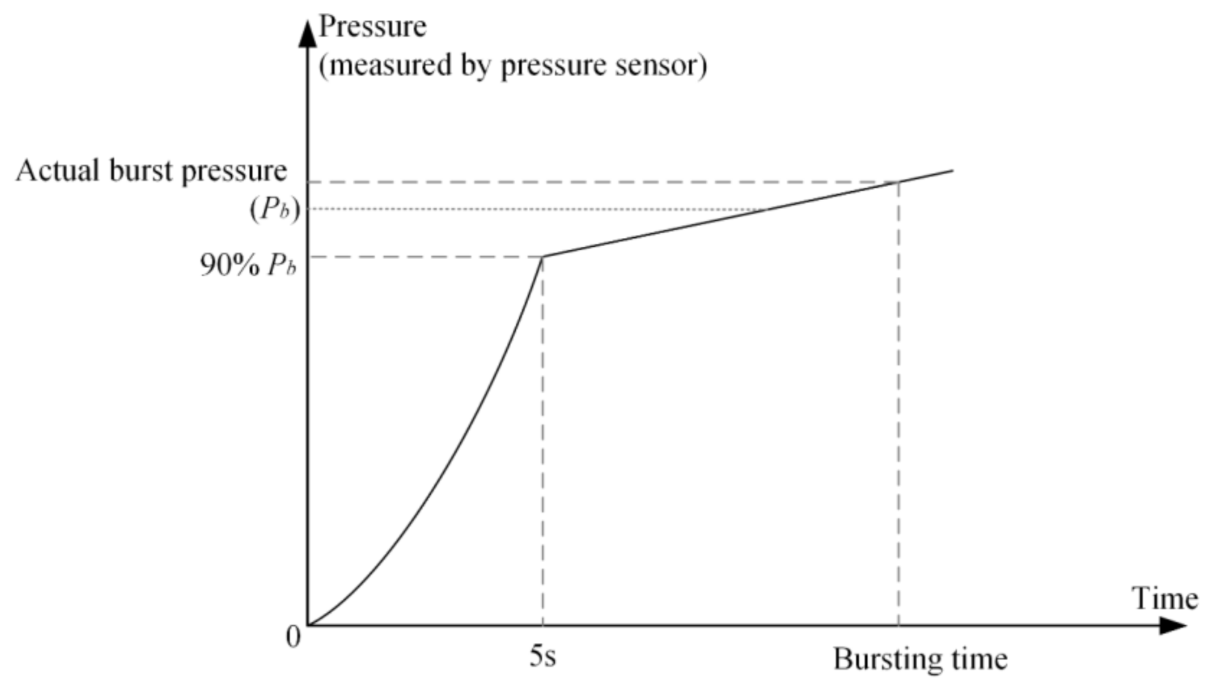
3.3. Experimental Equipment and Process

The overpressure medium used in this study was air. To ensure that the compressibility of air would not affect the experimental results, a temperature-controlled laboratory was prepared for this study as shown in Figure 6. The ambient temperature in the laboratory and the temperature of the source of compressed air were maintained at 20 °C at all times. Special hydraulic clamping equipment was used to ensure that the clamping force was uniform for each rupture disc. The theoretical burst pressure of a rupture disc was calculated by Equation 1, while the actual loading method to measure the burst pressure was based on the estimation and optimization methods from related studies [8,39]; the pressure loading scheme is shown in Figure 7.
When the rupture disc was stable in the clamping device, the clamping device was fixed, the electronic control valve was opened to 30%, and the pressure sensor on the clamping device was activated simultaneously. Compressed air impinged on the internal surface of the rupture disc. After 5 s, the pressure on the internal surface of the rupture disc reached 90% of the theoretical burst pressure (90% Pb). Then, the electronic control valve started to slowly open at a rate of 0.5% per 1 s, and the pressure on the internal surface of the rupture disc gradually increased. When the rupture disc broke, the compressed air quickly leaked out with a strong impact and an obvious sound, and then, the operation of the whole system was stopped.
Since there was an obvious pressure drop section, as shown in Figure 8 before and after a rupture disc burst, the pressure data before the drop were the actual burst pressure of the rupture disc. According to the above experimental methods, these burst pressure tests were all performed on batches of rupture discs, the test data were classified according to the shape, forming pressure and material type of the rupture discs, and the specific experimental data analysis was performed.

4. Analysis of Experimental Results

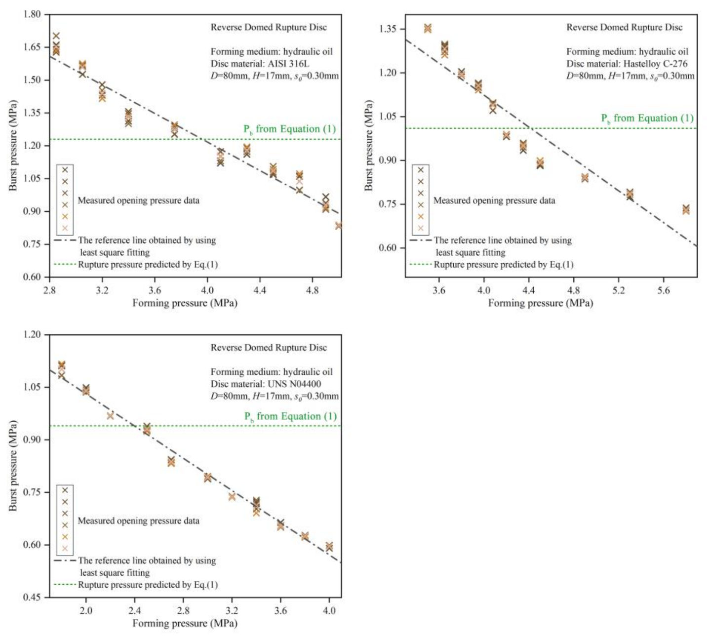
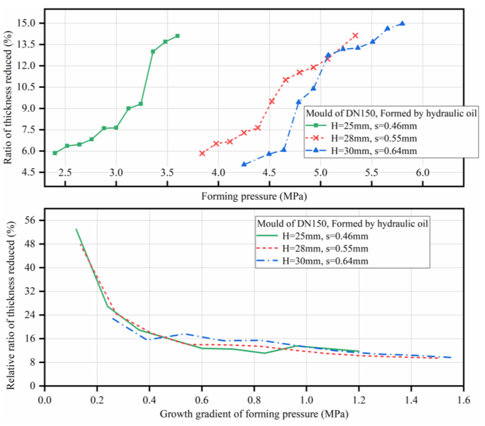
4.1. Analysis of the Burst Pressure Trends

According to the analysis and calculation methods above, the theoretical parameters controlling the burst pressure of the rupture discs mainly included the thickness of the material, the height of the arch top, the venting diameter, and the mechanical properties of the material. Therefore, the moulding methods, especially the effect of moulding pressure on the burst pressure of the rupture disc, were compared under the same conditions. The effects of the two forming media were also considered. The least square regression function in MATLAB software was used to analyse the trends in the experimental data with respect to the forming pressure. Figure 9, Figure 10, Figure 11, Figure 12, Figure 13 and Figure 14 show these experimental results.
The experimental data above have an obvious trend: when the forming pressure increases, the burst pressure of the rupture disc significantly decreases. At the same forming pressure, the burst pressure difference is small. The forming pressure is indeed an important factor affecting the burst pressure of the rupture disc. There is a negative correlation between the forming pressure and the burst pressure of the rupture disc. There are additional details for this relationship under specific conditions:
The difference in compressibility of the forming medium interferes with the change in forming pressure during forming. According to the above description of the moulding method, the strength of the moulding pressure was changed by controlling the speed of the motor for the pressure source for the moulding device in the study, and this speed adjustment was carried out (as far as possible) in accordance with the linear law to ensure the regular differentiation of the experimental data. However, due to the compressibility of air, Figure 8 and Figure 9 show that when the compressor speed increased, the forming pressure increased faster at the same time; in contrast, this trend was not apparent for the hydraulic forming process. This indicated that the hydraulic moulding method had better ability to control the forming pressure [40,41].
Additionally, the strain hardening exponent of the material has a strong response to the influence of the forming pressure. According to the analysis of Figure 13 and Figure 14, AISI 316L stainless steel has the highest strain hardening exponent and elastic modulus, which leads to a more obvious deviation and oscillation in the burst pressure variation trend of the rupture disc made of AISI 316L compared with the other two as the forming pressure changes. While Monel alloy UNS N04400 has the best processing toughness, the material is more likely to change towards the pre-set shape when deformation occurs and has a more regular trend of change.
Furthermore, for plates of the same material and with the same diameter, there was less variation among the extreme values of the burst pressure for thinner plates. Thinner plates have less flexural rigidity [42,43] and are less able to resist deformation. Additionally, they offer less resistance to forming, and their final structure more closely resembles the mould. This results in less variation in the burst pressure. The experimental results showed that the burst pressure data for a group of thin plates were more concentrated near the theoretical burst pressure, which can confirm the above conclusion.

4.2. Analysis of the Effect of Forming Pressure on Burst Pressure

The majority of studies on the instability of pressure on the spherical shell structures pay close attention to factors such as changes in the thickness and shape of the spherical shell structure during the forming process [44,45]. In this study, moulds and proximity sensors were used to control the structural shape of the rupture disc, so the thickness change in the structure in the weak area of the rupture disc was the main focus of concern. In this study, a new parameter for measuring the relationship between forming pressure and structure thickness—the relative ratio of thickness reduction (rf)—was proposed. Its calculation method is as follows:
r f = r i P f i P f , min , i = 1 ,   2 ,   3 ,   .   ,   n r i = s a r c h i ¯ s i × 100 %
where r i is the absolute ratio of the reduction in arch top position thickness related to the original material of the No. (i) type, s a r c h i ¯ is the average value of the spiral micrometre measurements of the thickness of the material at the arch top position for the No. (i) type, P f i is the actual moulding pressure of the No. (i) type, and P f , min is the minimum value of the moulding pressure for all test samples of the same type. This definition can be used to quickly compare the relationship between the decreasing rate of arch material thickness and the change in the forming pressure from its minimum value to its maximum value. Through this relationship, the internal cause of the correlation between burst pressure and forming pressure of rupture discs can be clearly found. The absolute and relative ratios of thickness reduction for different types of rupture discs under the same forming pressure are shown in Figure 15, Figure 16, Figure 17, Figure 18, Figure 19 and Figure 20.
The above figures clearly show that it can be seen from the figure that as the forming pressure increases, the ratio of thickness reduced will also increase. Additionally, the reference index r f proposed in this study has a very good reproducibility for the forming pressure and the reduction rate of the thickness at the top of the arch. This regularity can be explained as follows: when the forming pressure increases from its minimum, the thickness at the top of the arch is very sensitive to the initial pressure increase, and there is an obvious negative correlation between the thickness at the arch top and the forming pressure. However, in almost all models, the strength of the negative correlation began to decrease rapidly when the forming pressure increased by 0.4 to 0.6 MPa relative to the minimum forming pressure. Even if the forming pressure increased further, the thickness of the arch top position decreased increasingly slowly. This is because the deformation of the original plate is limited by the mould in the production process of the rupture disc. Even if the forming pressure increases further, the deformation height of the rupture disc does not change, so the plastic deformation at the upper end of the arch is limited, and the thickness reduction rate is also limited.
It was further found that the flexural rigidity of the original material of the blasting plate had a significant effect on the rate of reduction in the arch thickness. For example, under conditions of the same diameter and the same forming medium, the rate of change in the reduction in thickness at the top of the arch was faster for thinner plates. This is because thinner plates have less flexural rigidity [46] and undergo more plastic deformation, which leads to a faster decrease in the arch top position thickness. The difference in flexural stiffness could also explain the change in the thickness reduction rate of the rupture discs made from different materials. Of course, the basic mechanical parameters of the materials are affected not only by their composition but also by the method of heat treatment or sheet rolling, which requires further research. In general, the decrease in the thickness at the arch top is the main reason for the change in rupture disc opening pressure, and the change in thickness is caused by the different forming pressures in the production process. Moreover, due to the limitation of the mould, this influence has strong and weak action ranges.

5. Conclusions

After exploring the forming technology, especially the effect of forming pressure on the opening pressure of rupture discs, a new parameter, the relative ratio of thickness reduction, is proposed in this study.
Combining with the experimental data for burst pressures and the measurement results of the weakest element in the rupture disc structure, it is concluded that there is a negative correlation between the manufacturing forming pressure and the actual opening pressure of a rupture disc. The reason for this effect is that the thickness of the structure decreases because of the plastic deformation of the rupture disc during the forming process.
Furthermore, through research on the plastic instability of thin shell structures and sheet deformation, the flexural rigidity of the original plate is found to be the key physical parameter associated with the forming pressure and burst pressure. A plate with less flexural rigidity is more likely to obtain a smaller vault thickness under the action of a larger forming pressure, which leads to premature rupture and failure of the rupture disc.
These research results can provide strong research evidence for the optimization of the production process of rupture discs or the selection of the production method of rupture discs under different working conditions. It is hoped that future researchers will be able to verify the results of this research by considering different working conditions.

Author Contributions

Conceptualization, B.L. and W.L.; methodology, L.L. and X.L.; software, L.L. and C.Y.; validation, L.L., C.Y., and B.L.; formal analysis, L.L. and W.L; data curation, L.L. and W.L.; writing—original draft preparation, L.L., X.L. and C.Y.; writing—review and editing, L.L., X.L. and B.L.; visualization, all authors. All authors have read and agreed to the published version of the manuscript.

Funding

The Fundamental Research Funds for the Central Universities (Grant No. 2015XKMS024) of china and the Prioroty Academic Program Development of Jiangsu Higher Education Institutions (PAPD) of China.

Institutional Review Board Statement

Not applicable.

Informed Consent Statement

Not applicable.

Data Availability Statement

Not applicable.

Conflicts of Interest

The authors declare no conflict of interest.

References

  1. Lefebvre, D.; Leveneur, S. Special Issue on “Thermal Safety of Chemical Processes”. Processes 2021, 9, 1054. [Google Scholar] [CrossRef]
  2. Fu, G.; Zhao, Z. The accident path of coal mine gas explosion based on 24Model: A case study of the ruizhiyuan gas explosion accident. Processes 2019, 7, 73. [Google Scholar] [CrossRef] [Green Version]
  3. Looney, C.P.; Hagan, Z.M. Modelling the test methods used to determine material compatibility for hydrogen pressure vessel service. Int. J. Fatigue 2019, 132, 105339. [Google Scholar] [CrossRef]
  4. Salamonowicz, Z.; Krauze, A. Numerical Reconstruction of Hazardous Zones after the Release of Flammable Gases during Industrial Processes. Processes 2021, 9, 307. [Google Scholar] [CrossRef]
  5. Guojin, Z.; Yonghang, C.; Wenjing, Z.; Min, D. Research on evaluation and inspection of pressure relief valve. In Proceedings of the IOP Conference Series: Materials Science and Engineering, Xi’an, China, 8–11 October 2020; Volume 1043, p. 42017. [Google Scholar]
  6. Lee, H.S.; Yun, H.C. A study on the rupture disk design and application at the two phase flow by runaway reaction at batch reactor. J. Korean Inst. Gas 2017, 21, 1–8. [Google Scholar]
  7. Kim, J.D.; Kwon, K.S.; Rhim, J.G.; Yang, W.B. A Study on Flow Analysis according to the Cause of Gas Leakage in the Specialty Gas Supply Device for Semiconductors. J. Korean Inst. Gas 2021, 25, 42–51. [Google Scholar]
  8. Zhao, G. An easy method to design gas/vapor relief system with rupture disk. J. Loss Prev. Process. Ind. 2015, 35, 321–328. [Google Scholar] [CrossRef]
  9. Truckenbrodt, E. Elementare Strömungsvorgänge Dichteveränderlicher Fluide; Springer: Berlin/Heidelberg, Germany, 2008. [Google Scholar]
  10. Coker, A.K. Process Safety and Pressure-Relieving Devices. In Ludwig’s Applied Process Design for Chemical and Petrochemical Plants, 4th ed.; Gulf Professional Publishing: Houston, TX, USA, 2007; pp. 575–770. [Google Scholar]
  11. Shannak, B. Experimental and theoretical investigation of gas–liquid flow pressure drop across rupture discs. Nucl. Eng. Des. 2010, 240, 1458–1467. [Google Scholar] [CrossRef]
  12. Mutegi, M.K.; Schmidt, J. Challenges in sizing rupture disk vent line systems especially for compressible two-phase flow. Chem. Eng. Trans. 2016, 48, 631–636. [Google Scholar]
  13. Schmidt, J.; Claramunt, S. Sizing of rupture disks for two-phase gas/liquid flow according to HNE-CSE-model. J. Loss Prev. Process. Ind. 2016, 41, 419–432. [Google Scholar] [CrossRef]
  14. Kitabayashi, N.; Wada, Y. Experimental study on high pressure hydrogen jets coming out of tubes of 0.1–4.2 m in length. Int. J. Hydrogen Energy 2013, 38, 8100–8107. [Google Scholar] [CrossRef]
  15. Golovastov, S.; Bocharnikov, V. The influence of diaphragm rupture rate on spontaneous self-ignition of pressurized hydrogen: Experimental investigation. Int. J. Hydrogen Energy 2012, 37, 10956–10962. [Google Scholar] [CrossRef]
  16. Kim, Y.R.; Lee, H.J. A flow visualization study on self-ignition of high pressure hydrogen gas released into a tube. Proc. Combust. Inst. 2013, 34, 2057–2064. [Google Scholar] [CrossRef]
  17. Grune, J.; Sempert, K. Experimental investigation of flame and pressure dynamics after spontaneous ignition in tube geometry. Int. J. Hydrogen Energy 2014, 39, 20396–20403. [Google Scholar] [CrossRef]
  18. Kaneko, W.; Ishii, K. An experimental study on the mechanism of self-ignition of high-pressure hydrogen. Int. J. Hydrogen Energy 2017, 42, 7374–7379. [Google Scholar] [CrossRef]
  19. Devasenapathy, V.; Pathanjali, G.A. Laser technique in diaphragm cum rupture disc for defence oriented silver oxide zinc reserve batteries. Mater. Manuf. Process. 2018, 34, 1–8. [Google Scholar] [CrossRef]
  20. Gong, L.; Duan, Q. Effect of burst disk parameters on the release of high-pressure hydrogen. Fuel 2019, 235, 485–494. [Google Scholar] [CrossRef]
  21. Schrank, M. Investigation on the degradation and opening behavior of knife blade burst disks. J. Loss Prev. Process. Ind. 2014, 32, 161–164. [Google Scholar] [CrossRef]
  22. Zhu, H.B.; Xu, W.P.; Luo, Z.P. Finite Element Analysis on the Temperature- Dependent Burst Behavior of Domed 316L Austenitic Stainless Steel Rupture Disc. Met. Open Access Metall. J. 2020, 10, 232. [Google Scholar] [CrossRef] [Green Version]
  23. Jeong, J.Y.; Lee, J. A study on the grooving process of a cross-scored rupture disc. Int. J. Precis. Eng. Manuf. 2012, 13, 219–227. [Google Scholar] [CrossRef]
  24. Kong, X.; Zhang, J.; Li, X.; Jin, Z.; Zhong, H.; Zhan, Y.; Han, F. Experimental and finite element optimization analysis on hydroforming process of rupture disc. Procedia Manuf. 2018, 15, 892–898. [Google Scholar] [CrossRef]
  25. Chung, P.W.H.; Yang, S.H. Conceptual design of pressure relief systems. J. Loss Prev. Process. Ind. 2000, 13, 519–526. [Google Scholar] [CrossRef]
  26. Xu, W.P.; Liu, Y.T. Study on Conventional Domed Bursting Disc Material and Burst Pressure Test. Adv. Mater. Res. 2013, 690-693, 2371–2378. [Google Scholar] [CrossRef]
  27. Lee, D.W.; Park, J.M. Effect of rupture disc curvature on the compression waves in S/R valve. J. Mech. Sci. Technol. 2008, 22, 755–760. [Google Scholar] [CrossRef]
  28. Luo, G.M.; Hsu, Y.C. Nonlinear buckling strength of out-of-roundness pressure hull. Thin Walled Struct. 2018, 130, 424–434. [Google Scholar] [CrossRef]
  29. Jeong, J.Y.; Jo, W. Structural analysis on the superficial grooving stainless-steel thin-plate rupture discs. Int. J. Precis. Eng. Manuf. 2014, 15, 1035–1040. [Google Scholar] [CrossRef]
  30. Liu, Y.; Li, M.; Ren, X. Flow stress prediction of Hastelloy C-276 alloy using modified Zerilli− Armstrong, Johnson− Cook and Arrhenius-type constitutive models. Trans. Nonferrous Met. Soc. China 2020, 30, 3031–3042. [Google Scholar] [CrossRef]
  31. Li, L.; Li, N. Experimental study on heat transfer process in boilers to predict thermal strain/stress distribution and deformation risk of membrane walls. Process. Saf. Environ. Prot. 2020, 138, 186–198. [Google Scholar] [CrossRef]
  32. Wang, W.; Lu, Y. Research on large deflection deformation reconstruction of elastic thin plate based on strain monitoring. Measurement 2020, 149, 107000. [Google Scholar] [CrossRef]
  33. Li, H.W. Whole-process modeling of titanium disc forming for gradient distributions of temperature and deformation. Chin. J. Aeronaut. 2020, 33, 3550–3563. [Google Scholar] [CrossRef]
  34. Zhou, H.; Geng, T. Deformation simulation of the panel mold in the pressing process. Eng. Anal. Bound. Elem. 2005, 29, 894–902. [Google Scholar] [CrossRef]
  35. Bukhvostova, A.; Russo, E. Comparison of DNS of compressible and incompressible turbulent droplet-laden heated channel flow with phase transition. Int. J. Multiph. flow 2014, 63, 68–81. [Google Scholar] [CrossRef] [Green Version]
  36. Godderidge, B.; Turnock, S. The effect of fluid compressibility on the simulation of sloshing impacts. Ocean. Eng. 2009, 36, 578–587. [Google Scholar] [CrossRef]
  37. Sudha, C.; Parameswaran, P. Microstructure and deformation mode of a stainless steel rupture disc exposed to sodium–water reaction. Mater. Charact. 2008, 59, 1088–1095. [Google Scholar] [CrossRef]
  38. Nurick, G.N.; Shave, G.C. The deformation and tearing of thin square plates subjected to impulsive loads—An experimental study. Int. J. Impact Eng. 1996, 18, 99–116. [Google Scholar] [CrossRef]
  39. Mutegi, M.K.; Schmidt, J. Sizing rupture disk vent line systems for high-velocity gas flows. J. Loss Prev. Process. Ind. 2019, 62, 103950. [Google Scholar] [CrossRef]
  40. Meshalkin, V.P.; Belyakov, A.V. Methods Used for the Compaction and Molding of Ceramic Matrix Composites Reinforced with Carbon Nanotubes. Processes 2020, 8, 1004. [Google Scholar] [CrossRef]
  41. Gearing, D.; Mevissen, D. Hydroforming systems, equipment, controls and tooling—ScienceDirect. Hydroforming Adv. Manuf. 2008, 5, 33–51. [Google Scholar]
  42. Kumar, A.; Chanda, A.K.; Angra, S. Analysis of effects of varying face sheet thickness on different properties of composite sandwich Structure. Mater. Today Proc. 2021, 38, 116–121. [Google Scholar] [CrossRef]
  43. Lin, Y.; Zhong, C. Experimental Study on the Flexural Behavior of Concrete-Filled Steel Box Slabs. Processes 2021, 9, 649. [Google Scholar] [CrossRef]
  44. Ma, Q.; Zhu, Y. Buckling and strength of an externally pressurized spherical shell with reinforced opening. Int. J. Press. Vessel. Pip. 2018, 165, 11–19. [Google Scholar] [CrossRef]
  45. Alexandrov, S.; Lyamina, E. Plastic Bending at Large Strain: A Review. Processes 2021, 9, 406. [Google Scholar] [CrossRef]
  46. Nazarov, S.A.; Sweers, G.H. The flexural rigidity of a thin plate reinforced with periodic systems of separated rods. J. Appl. Math. Mech. 2010, 74, 313–322. [Google Scholar] [CrossRef]
Figure 1. The form and installation method of the rupture disc in the study.
Processes 09 01775 g001
Figure 2. Description of the rupture disc’s design parameters.
Processes 09 01775 g002
Figure 3. (a) Tensile test specimens; (b) Stress–strain curves for different substrates of rupture discs.
Processes 09 01775 g003
Figure 4. Manufacturing equipment for rupture discs.
Processes 09 01775 g004
Figure 5. Forming mould base and rupture discs of different materials.
Processes 09 01775 g005
Figure 6. Schematic diagram of the experimental equipment.
Processes 09 01775 g006
Figure 7. Loading method for the burst pressure of rupture disc.
Processes 09 01775 g007
Figure 8. Pressure curve of the experimental device before-after a rupture disc opened.
Processes 09 01775 g008
Figure 9. For the pneumatic forming method, the relationship between the burst pressure and the forming pressure of rupture discs with a diameter of 50 mm.
Processes 09 01775 g009
Figure 10. For the pneumatic forming method, the relationship between the burst pressure and the forming pressure of rupture discs with a diameter of 100 mm.
Processes 09 01775 g010
Figure 11. For the hydraulic forming method, the relationship between the burst pressure and the forming pressure of rupture discs with a diameter of 80 mm.
Processes 09 01775 g011
Figure 12. For the hydraulic forming method, the relationship between the burst pressure and the forming pressure of rupture discs with a diameter of 150 mm.
Processes 09 01775 g012
Figure 13. For the pneumatic forming method, the relationship between the burst pressure and the forming pressure of rupture discs with different materials with a diameter of 100 mm.
Processes 09 01775 g013
Figure 14. For the hydraulic forming method, the relationship between the burst pressure and the forming pressure of rupture discs with different materials with a diameter of 80 mm.
Processes 09 01775 g014
Figure 15. Absolute and relative ratios of thickness reduction for Dn 50 mm rupture discs formed by air.
Processes 09 01775 g015
Figure 16. Absolute and relative ratios of thickness reduction for Dn 100 mm rupture discs formed by air.
Processes 09 01775 g016
Figure 17. Absolute and relative ratios of thickness reduction for Dn 80 mm rupture discs formed by hydraulic oil.
Processes 09 01775 g017
Figure 18. Absolute and relative ratios of thickness reduction for Dn 150 mm rupture discs formed by hydraulic oil.
Processes 09 01775 g018
Figure 19. Absolute and relative ratios of thickness reduction for Dn 100 mm rupture discs with different materials.
Processes 09 01775 g019
Figure 20. Absolute and relative ratios of thickness reduction for Dn 80 mm rupture discs with different materials.
Processes 09 01775 g020
Table 1. Statistics for the modelling parameters and moulding methods of test samples.
Type of MouldHeight of Arch Top (H)Plate Thickness (s)Plate MaterialsTheoretical Forming Pressure (Pb)Compression Forming Medium
Dn50mm9 mm0.2 mmAISI 316L2.52 MPaAir
10 mm0.25 mm3.17 MPa
11 mm0.3 mm3.72 MPa
Dn80mm16 mm0.2 mmAISI 316L2.63 MPaHydraulic oil
17 mm0.3 mm3.01 MPa
18 mm0.4 mm3.32 MPa
17 mm0.3 mmUNS N044002.55 MPa
17 mm0.3 mmHastelloy C-2763.28 MPa
Dn100mm20 mm0.38 mmAISI 316L2.66 MPaAir
22 mm0.46 mm3.81 MPa
24 mm0.56 mm4.27 MPa
20 mm0.38 mmUNS N044002.33 MPa
20 mm0.38 mmHastelloy C-2762.58 MPa
Dn150mm25 mm0.46 mmAISI 316L2.72 MPaHydraulic oil
28 mm0.55 mm3.89 MPa
30 mm0.64 mm4.45 MPa
Publisher’s Note: MDPI stays neutral with regard to jurisdictional claims in published maps and institutional affiliations.

