Article

Effects of Pulse Voltage Duration on Open–Close Dynamic Characteristics of Solenoid Screw-In Cartridge Valves

1
Energy and Power Engineering College, Lanzhou University of Technology, Lanzhou 730050, China
2
Key Laboratory of Fluid Machinery and Systems, Lanzhou 730050, China
*
Author to whom correspondence should be addressed.
Processes 2021, 9(10), 1722; https://doi.org/10.3390/pr9101722
Submission received: 12 August 2021 / Revised: 19 September 2021 / Accepted: 22 September 2021 / Published: 25 September 2021

Abstract

:
The hydraulic high-speed on/off valve (HSV)—the critical core component of digital hydraulic technology—has a special structural design and manufacture due to its fast opening and closing, which results in high prices and maintenance costs. The solenoid screw-in cartridge valve (SCV) is widely used in the hydraulic industry because of its merits, such as mature technology, reliable quality, and low cost. The contribution of this study is to replace the high-speed on/off valve with the SCV in some areas of application by introducing positive and negative pulse voltage control for the coil of the SCV, which only modifies the control circuit and needs no change in structure. Based on the analysis of the structure of the SCV, the simulation model was developed in AMESim and validated by experiments to investigate the effects of the pulse voltage duration on the open–close dynamic characteristics and find the optimal pulse voltage duration, so that the SCV can open or close in the shortest time to reduce energy loss as far as possible. The simulation results showed that the positive and negative pulse voltage could quicken the rising or declining speed of the coil current and dramatically decrease the opening and closing delay time. By the experimental comparison with the original control method, the opening time of the SCV decreased from 30 ms to 13 ms, and the closing time was reduced from 139 ms to 14 ms.

1. Introduction

The high-speed on/off valve is a key and essential hydraulic component in modern digitally controlled fluid power systems because of its excellent switching performance, compact structure, and anti-pollution abilities. The fast switching of HSVs is a very important parameter that determines the performance of the whole digital hydraulic system. To obtain perfect open–close characteristics for HSVs, strenuous efforts in structure innovation and control optimization have been made by many scholars at home and abroad.
In terms of structural innovation, some new types of valve spool and material have been proposed and adopted for improving the performance of the HSV. L.C. Passarini et al. investigated the importance of the spool and armature mass on the dynamic performance of HSVs [1]. S. Wu et al. developed a cone valve type of HSV with a hollow spool structure [2,3]. Ruan et al. designed a 2D valve whose spool has two degrees of freedom (rotary and sliding), which can realize a fast response [4,5,6]. Kong et al. investigated a new scheme of parallel coils wherein the single coil of the solenoid is replaced by parallel coils with the same ampere-turns, further improving the dynamic performance of the HSV [7]. Moreover, some new materials have been applied to improve dynamic performance. Meng et al. proposed the use of magnetostrictive materials for pulse jet switch valves as electromagnetic conversion components, shortening the switching time of the pulsed jet on/off valve [8,9,10]. Yu et al. designed a piezoelectric (PZT) direct-acting high-speed switching valve and a bridge-type displacement amplification structure in order to improve the lack of rapidity and large flow [11].
Optimization control strategies are also an effective and convenient method to improve the response speed and energy efficiency of the existing HSV with no structural changes. Su proposed the adaptive double voltage control method for achieving the suitable oil-supplied mouth pressure and control mouth pressure [12]. Zhao et al. studied the effects of different boost voltages and currents on the dynamic characteristics of HSVs, finding the optimal boost voltage and current considering both dynamic performance and energy consumption characteristics [13,14]. Based on the double voltage control method, Lee et al. further improved the dynamic characteristics of HSVs using a driving circuit with three different voltages [15]. Zhong et al. proposed a three-power-sources excitation control algorithm for high-speed on/off valves based on current feedback in order to improve the dynamic performance of HSVs and reduce the temperature rise and energy consumption [16,17]. Furthermore, Gao et al. proposed a compound adaptive PWM control method based on a state-variable feedback algorithm, which not only improves the dynamic characteristics of the HSV, but also greatly reduces its energy loss [18,19].
Based on the analysis of the above studies, the research object of structural optimization and control strategy optimization is the HSV, but the price of HSVs on the market is high, which results in high production and application costs for digital hydraulic systems. Conversely, the commercial products of solenoid screw-in cartridge valves (SCVs) from the companies SUN and HydraForce, with well-rounded technology, bargain prices, and reliable quality, have been widely applied in hydraulic systems. However, there is a large gap between the dynamic characteristics of the solenoid screw-in cartridge valve and the HSV, which needs to be improved to meet the requirements of digital hydraulic technology. As with the HSV, control strategy optimization is the best choice because it can optimize the dynamic characteristics of the cartridge valve without increasing the cost, whereas the research on improving the dynamic characteristics of SCVs via optimized control strategies is deficient.
In this paper, we propose a positive and negative pulse voltage control strategy applied to the SCV based on the interaction relationships between driving voltage, coil current, and spool movement. A simulation model for SCVs was developed to explore the influence of open–close characteristics of SCVs affected by pulse voltage duration, and to obtain the optimal pulse voltage time that was finally determined for the SCV. This research not only improves the dynamic characteristics of SCVs and makes it possible for them to work properly in some digital hydraulic systems, but also makes a contribution to filling the gaps in this knowledge.

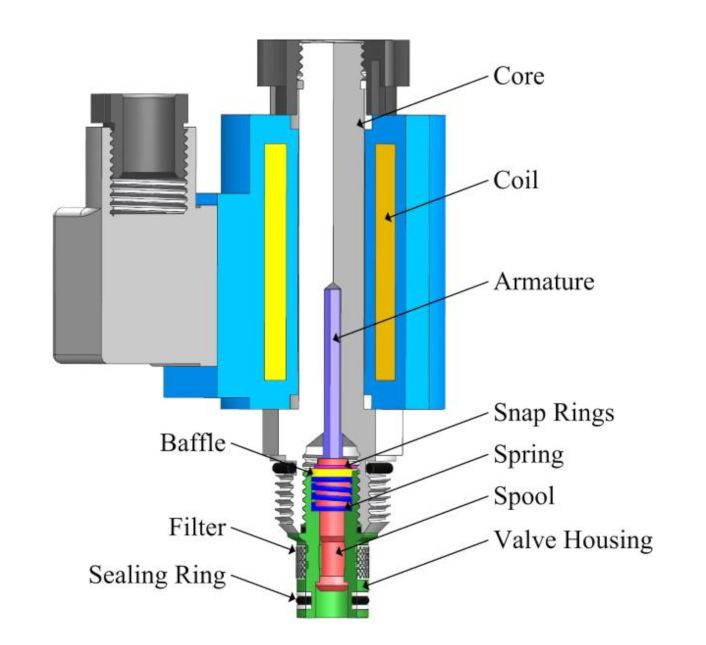
2. Valve Configuration

The configuration of the SCV considered in this study is shown in Figure 1; it consists of the solenoid and a two-position and two-way normal/closed directional valve. The main components of the solenoid are the core, coil, and armature. The directional valve is composed of spring, spool, valve housing, etc. The opening process of the SCV is demonstrated in Figure 2a. When the solenoid is energized, the electromagnetic force Fe generated by the coil acts on the right end of the valve spool through the armature. With the increase in the current in the coil, the electromagnetic force begins to overcome the pre-tightening force of the spring, and pushes the spool to move to the left side. The hydraulic oil flows from port P into port T through the annular flow area between the spool and the valve seat. The closing operation of the SCV is represented in Figure 2b. If the solenoid is de-energized, the electromagnetic force output of the solenoid is zero. The spool is pushed back to the original position under the spring force. At this time, the valve is in a normally closed state, which blocks the flow of the hydraulic oil from port P into port T.

3. Mathematical Modeling

The operation of the SCV is the result of the multifield coupling of mechanical, electromagnetic, and hydrodynamic properties, which can be modeled mathematically from the above physical fields.

3.1. Mechanical Characteristics

The SCV mechanics dynamic model considers both the spool and the armature mass. The forces on the armature and the spool are displayed in Figure 3. The armature motion is mainly affected by the electromagnetic force and the reaction force of the spool. The spool motion is under the combined effect of the armature thrust, spring force, hydrodynamic force, damping force, etc.
The dynamic equations of the armature and spool can be expressed as:
m p x ¨ p   =   F e   +   F p a     F c     F p v f     F p b     F s f a F p a   =   P a A a F p v f   =   B p x ˙ p F p b   =   P b A a ,
m s x ¨ s   =   F c   +   F s a     F s s     F f d     F s b     F s v f     F s f s F s a   =   P b A b F s s   =   K ( x 0   +   x s ) F s v f   =   B s x ˙ s F s b   =   P c A b ,
where xs and xp are the displacements of the armature and spool, respectively. Since the armature and spool are tightly attached during the movement, it can be considered that xs is equal to xp. ms and mp are the mass of the armature and spool, respectively; Fe is the electromagnetic force, while Fpa, Fpb, Fsa, and Fsb are the hydraulic pressure of the armature and spool. Aa and Ab are the effective areas of the armature and spool, respectively; Fc is the reaction force of the spool; Fpvf and Fsvf are the viscous damping coefficient of the armature and spool, respectively; and Pa, Pb, and Pc are the hydraulic pressure of the volume chambers A, B, and C, respectively. Since chambers A, B, and C are connected to the tank, it can be considered that Pa = Pb = Pc = 0. Fss is the compression force of the spring, K is the stiffness of the spring, x0 is the initial compression of the spring, Ffd is the hydrodynamic force on the spool, and Fsfa and Fsfs are the static friction on the armature and spool, respectively.
According to Equations (1) and (2), the mechanical dynamics of the SCV can be expressed as:
m x ¨ s   =   F e     B x ˙ s     K ( x 0   +   x s )     F f d     F f ,
where m is the total weight of the armature and the spool, B is the total viscous damping coefficient of the solenoid valve (B = Bs + Bp), and Ff is the total static friction force of the solenoid valve.

3.2. Electromagnetic Characteristics

The electromagnetic force is generated by exciting the electromagnetic coil. To analyze the electromagnetic properties of the solenoid coils, the magnetic resistance of the magnetizer steel is ignored. The characteristic of the magnetic can be expressed as:
F e   =   1 2   ×   I 2   ×   d L d δ ,
where I is the current of the solenoid coil, L is the inductance of the coil, and δ is the gap between the spool and the armature.
In the case of unsaturated electromagnets, the coil inductance can be expressed as:
L   =   N 2 G δ ,
where N is the number of turns of the solenoid coil and Gδ is the magnetic permeability of the air gap. The magnitude of the air gap permeability varies with the shape of the magnetic poles and the size of the air gap. Assuming that the magnetic flux is uniformly distributed in the air gap, the air gap permeability can be expressed as:
G δ   =   μ 0   ×   K f S δ ,
where μ0 is air permeability and S is the cross-section area of the armature. Kf is a coefficient of magnetic flux that expands from the edge of the magnetic pole through the air gap, increasing with the increase in δ.
According to Equations (4)–(6), the electromagnetic force of the solenoid coil can be written as:
F e   =   1 2   ×   ( I N ) 2   ×   μ 0 S δ 2 ,
In static conditions (on or off), the equivalent inductance of the coil can be considered as a constant. The solenoid coil can be simplified as a series connection of resistance and inductance. The dynamic equation of the coil current can be expressed as:
I   =   I i   +   ( U R     I i ) ( 1     exp ( t R L ) ) ,
where U is the excitation voltage of the coil, L is the equivalent inductance of the coil, R is the internal resistance of the coil, Ii is the initial current of the coil, and t is the time.

3.3. Hydrodynamic Characteristics

According to the flow characteristic formula, the flow rate through the valve can be expressed as:
Q   =   C d A 2 Δ p ρ ,
where Q is the flow rate of the valve, Cd is the flow coefficient, A is the open area of the orifice, ΔP is the pressure difference between port P and port T, and ρ is the oil density.
The movement of the spool is affected by hydrodynamic forces when the oil flows through the spool. The hydrodynamic force consists of steady flow force and transient flow force, and is affected by the changes in oil flow direction and velocity. The steady flow force and the transient flow force can be written as:
F f d   =   F s   +   F i F s   =   C d C v π d m sin ( 2 α ) x s Δ P F i   =   C d π l 2 ρ Δ P x ˙ s ,
where Fs is the steady flow force, Fi is the transient flow force, Cv is the fluid velocity coefficient, dm is the average diameter of the valve seat chamfer, α is the flow angle, and l is the damping length.

3.4. Dynamic Characteristic Analysis

At the critical moving moment of the spool, the terms dxs/dt and dxs2/dt2 are zero. Hence, the critical electromagnetic force can be expressed as:
F e o n   =   K x   ±   F f ,
where Feon is the critical electromagnetic force and x is the amount of compression of the spring.
When the SCV operates at the critical moment of transitioning from off to on, the frictional force and spring force are in the same direction. Thus, Equation (11) can be improved to:
F e o n   =   K x 0   +   F f ,
On the other hand, when the SCV operates at the critical moment transitioning from on to off, the frictional force is against the spring force. Thus, Equation (11) can be altered to:
F e o n   =   K ( x 0   +   x s )     F f ,
By combining Equations (7), (12) and (13), the critical current at the switching moment could be written as:
I e o n   =   1 N 2 ( K x 0   +   F f ) δ o n 2 μ 0 S ,
I e o f f   =   1 N 2 [ K ( x 0   +   x s )     F f ] δ o f f 2 μ 0 S ,
where Ieon is the critical opening current, Ieoff is the critical closing current, and δon and δoff are the air gap when the SCV operates at off and on status, respectively.
By combining Equation (8), the delay times of the valve opening and closing processes can be written as:
t e o n   =   L o n R ln 1     R N U o n 2 ( K x 0   +   F f ) δ o n 2 μ 0 S 1 ,
t e o f f   =   L o f f R ln ( 1   +   I e o f f R     I o f f R U o f f     I e o f f R )       ( 0   <   I e o f f   <   I o f f ) ,
where teon and teoff are the opening delay time and closing delay time, respectively; Lon and Loff are the equivalent inductance when HSV operates at off and on status, respectively; Uon and Uoff indicate the on-loading voltage and offloading voltage, respectively; and Ioff is the coil current when the SCV operates at off status.
According to Equations (16) and (17), it is easy to find the following:
  • A large driving voltage Uon is effective to reduce teon. When Uoff is less than Ieoff, a small or even negative voltage is effective in diminishing teoff;
  • A small initial current Ioff is helpful to decrease teoff at the closing stage;
  • A small spring preload force is conducive to make teon smaller at the opening stage, but a large spring preload force is beneficial to decrease teoff at the closing stage.

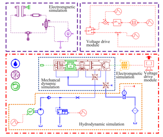
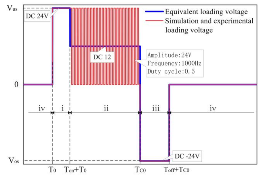
4. Simulation Modeling and Control Strategy

According to the structure and working principle of the SCV, the simulation model of the SCV was built using AMESim software, as shown in Figure 4. The simulation model consists of four parts: hydrodynamic simulation, electromagnetic simulation, mechanical dynamic simulation, and voltage drive modules. In order to improve the simulation accuracy of the SCV, our research used the HCD library and the electromechanical library in AMESim to model the mechanical dynamics simulation and the electromagnetic simulation of the SCV. The logic control library was also used to form the drive module.
The dynamic response simulation of a single opening and closing cycle of the SCV under a rated drive voltage is shown in Figure 5. From the simulation study, the whole process can be divided into six stages: the opening delay ①, opening movement ②, opening holding ③, closing delay ④, closing movement ⑤, and closing holding ⑥. Furthermore, the opening holding stage is divided into the current rising stage I and the current stable stage II.
It can be seen from Figure 5 that the opening dynamic characteristics of the SCV are determined by the opening delay ① and opening movement ②, while the closing characteristics are determined by the closing delay ④ and closing movement ⑤. Therefore, the opening and closing dynamic characteristics of the SCV will be greatly improved by shortening the time of these four stages. To achieve this goal, the positive and negative pulse voltage control strategy (as shown in Figure 6) was applied to the coil in the solenoid to advance the valve opening and closing response. The new control strategy contains four stages: the opening high voltage loading stage (i), rated voltage loading stage (ii), closing reverse voltage loading stage (iii), and closing voltage holding stage (iv).
The driving voltages of different stages have different effects on the opening and closing stages of the valve. The driving voltage (i) excites the solenoid coil in the opening delay ① and the opening movement ②, such that the current and the electromagnetic force of the coil quickly reach their maximum values. Meanwhile, the spool also possesses the maximum acceleration, which causes the shortest time of the opening delay ① and opening movement ②. In contrast to the driving voltage (i), the driving voltage (iii) in the opposite direction serves to accelerate the coil current unloading, so that the current quickly drops to the critical closing current, or even to zero. Thus, the spool is quickly closed under the supply of the spring force, and the closing response speed of the SCV is improved. The driving voltages (ii) and (iv) excite the solenoid coil in the opening holding ③ and the closing holding ⑥, respectively, to keep the spool open or closed under the supply of the rated voltage. It is clear that positive and negative pulse voltage duration Ton and Toff have a very important influence on the opening and closing dynamic characteristics of the SCV.

5. Simulation and Experimental Results

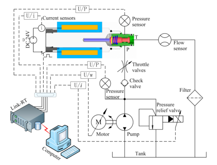
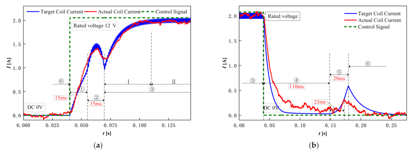
5.1. Experimental Validation of Simulation Model

The test apparatus of the SCV consists of an inverter motor, a solenoid cartridge valve, a fixed displacement pump, a pilot-operated solenoid relief valve, two pressure sensors, a current sensor, a throttle valve, and a semi-physical simulation platform. Figure 7 presents in detail the schematic diagram of the entire system, the main performance parameters of which are listed in Table 1. The photograph of the experimental prototype is displayed in Figure 8.
A nominal actuation voltage of 12 V was used in the simulation and experiment to verify the model. The simulated and tested solenoid coil current results are shown in Figure 9 during the opening and closing of the SCV. From the analysis in Figure 9a, the experimental results are consistent with the simulation results, in which the opening delay time and the opening moving time were both 15 ms. From Figure 9b, a very poor closing performance can be observed under the rated voltage driving condition. The closing delay time of both the simulation and experiment is almost 110 ms, and the simulated and experimental results of the closing motion time are 23 ms and 29 ms, respectively. From the results in Figure 9a,b, there is a very good agreement between the simulated and experimental results.

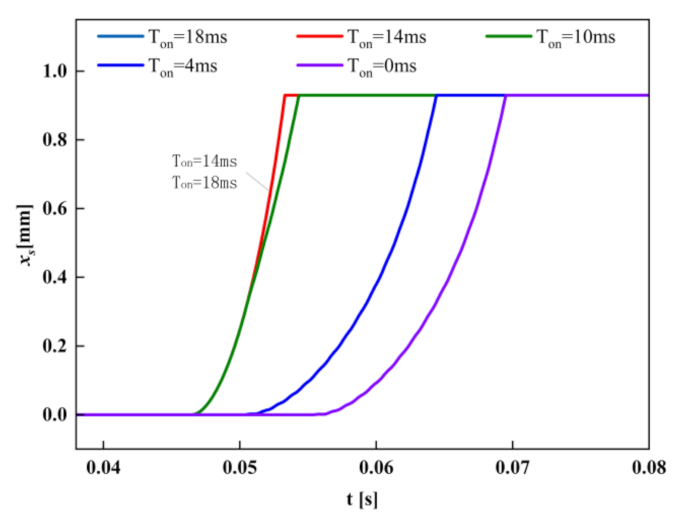
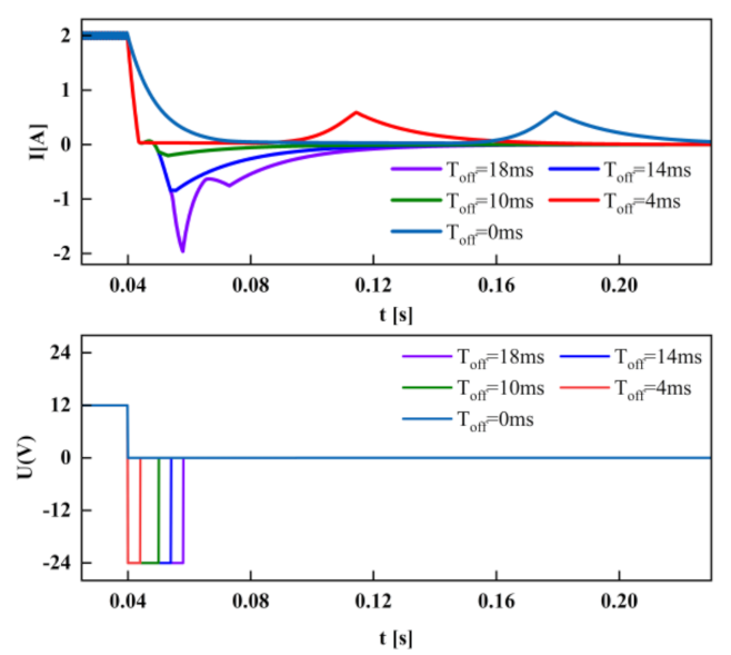
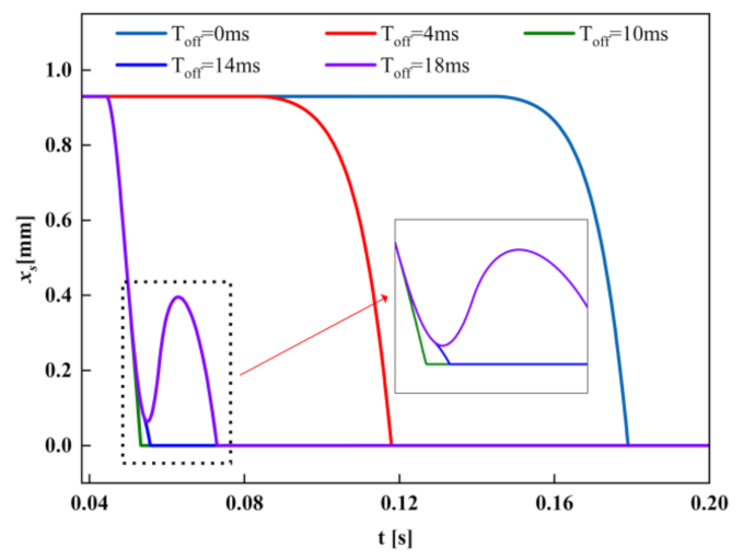
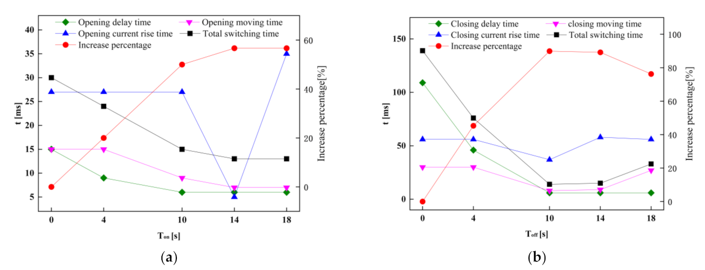
5.2. Effects of the Different Ton and Toff on Open–Close Characteristics of the SCV

In accordance with the proposed control strategy in Figure 6, a DC24V power and PWM control technology were utilized to generate the control voltage (as depicted in Figure 10). The duty cycles of 24 V and 12 V are 1 and 0.5, respectively, and the frequency of the PWM is 1000 Hz.
Based on the validated simulation model, the coil current and spool displacement response analysis of the switching process of the SCV under different positive and negative pulse voltage durations Ton and Toff were carried out. The changes in the coil current, voltage signal, and spool displacement of the opening and closing processes are illustrated in Figure 11, Figure 12, Figure 13 and Figure 14, respectively.
It is easily observable from Figure 11 that the rising rate of the coil current with a 24 V power supply is much greater than that driven by the conventional 12 V. With a 24 V supply, the coil current has the same rising rate in the early stages, and a quite different one along with the variation in positive pulse voltage duration Ton. Depending on the relationship between Ton and each opening stage of the SCV, the findings can be divided into the following three categories:
① The first case is 0 < Ton ≤ TS − T0, which means that the end time of the positive pulse voltage is at the valve opening delay stage. The coil is excited by the 24 V voltage only in Ton. The time spent by the coil to reach Ieon decreases with the increases in Ton, and the opening delay time decreases accordingly. The opening moving stage and the opening holding stage are not influenced by the positive pulse voltage, and the coil current dynamic characteristics are the same;
② The second case is TS − T0 < Ton ≤ TSE − T0, and the end time of the positive pulse voltage is extended to the opening movement stage of the SCV correspondingly. The opening delay time is shortened to the minimum because the positive pulse voltage is always fed into the coil throughout the whole opening delay stage. The coil current ISE also raises with the growth in Ton. The coil current dynamic characteristics remain unchanged in the opening holding stage;
③ The last case is TSE − T0 < Ton. In this condition, the solenoid coil is provided with positive high voltage until the spool is fully open. Both the opening delay and the opening moving time are reduced to their minima and maintained. If the coil is also excited by the overshoot voltage in the opening holding stage, the coil current will increase continuously or even exceed the stable current IST. Excessive coil current will reduce the service life of the electromagnetic coil and increase energy loss. Therefore, the coil current and Ton should be as small as possible in the conditions satisfying the opening dynamic. Furthermore, Figure 12 shows that excessive Ton is of no benefit to speeding up the opening of the SCV.
As shown in Figure 13 and Figure 14, due to the addition of negative pulse voltage, the decline rate of the coil current becomes greater than the original decline controlled by conventional voltage, which greatly shortens the closing time of the SCV. Similarly, the different negative pulse voltage durations Toff also have a noticeable effect on the valve closing process. Based on the time TC, the whole research of the valve closing process can be divided into two parts:
① At 0 < Toff ≤ TC − TC0, the coil is excited by the negative pulse voltage only in the closing delay stage. The coil current of the SCV decreases rapidly with the increase in Toff, and the closing delay time is shortened. The coil is not affected by the negative pulse voltage in the closing movement stage, and the current dynamic characteristic has no change;
② At TC − TC0 < Toff, the solenoid coil is always energized by the negative pulse voltage during the closing delay stage, which causes the coil current to rapidly dip to the critical closing current. The closing delay time of the SCV also becomes the minimum value. With the increase in the negative voltage duration Toff, the coil current first rapidly decreases to 0 V, and then gradually increases in the reverse direction during the closing movement stage. The thrust produced by the reverse current will impede the closing motion of the spool (Toff = 10 ms, 14 ms), and may even make the spool open once again (Toff = 18 ms). For this reason, the spool closing time of the SCV lengthens with the increase in reverse current, as shown in Figure 14.
The simulation results of each stage and the total time of the valve opening and closing process under different Ton and Toff are shown in Figure 15. It is easily observable from Figure 15a that the spool response speed of the SCV is improved with the increase in the positive pulse voltage duration Ton. The total opening time is 30 ms when Ton is 0 ms, which is shortened to 13 ms under a Ton of 14 ms. The opening delay time and the opening motion time are 6 ms and 7 ms, respectively, with the same 14 ms Ton. The opening dynamic characteristics of the SCV after introducing a new pulse voltage control strategy are improved by 56.67% compared to the original method.
Figure 15b shows that the total closing time is 139 ms when Toff is equal to 0 ms, and becomes 14 ms by employing a 10 ms Toff. The closing delay time and the closing motion time are 6 ms and 8 ms, respectively, under the same Toff conditions. Hence, the open–close dynamic characteristics of the SCV can be greatly improved by selecting the appropriate Ton and Toff.

5.3. Experimental Verification

According to the above simulated analysis of the coil current and spool displacement dynamic characteristics of the SCV, pulse voltage durations Ton and Toff of 10 ms can offer high response speed and reduce the consumption of electric energy by the solenoid. The coil current curves of the experiment and simulation are shown in Figure 16, showing good agreement between the simulated and experimental results, which verifies the above simulation method, the results of which can be used for SCV optimization.

6. Conclusions

In this paper, the sophisticated and cost-effective solenoid screw-in cartridge that is easily accessible in the market was taken as the research object, and the positive and negative pulse voltage control method was applied to the valve to improve its open–close response speed. A detailed simulation model that includes mechanical, hydraulic, electromagnetic, and control subjects was established based on AMESim to probe the influence law of pulse voltage duration on the coil current and spool displacement dynamic characteristics, and to obtain the optimal Ton and Toff for the SCV. This study finds that the opening and closing delay stages, which have always been a major drag on the valve response, can be compressed by the use of appropriate pulse voltage duration. Simulated and experimental results confirm that the best opening and closing times of the valve are 13 ms and 14 ms, representing an improvement of 56.7% and 89.9%, respectively. The sharp decline in opening and closing times gives the SCV the chance to replace the HSV in digital hydraulic systems. Meanwhile, this research can provide a theoretical basis for the application of the pulse voltage control method in improving the dynamic characteristics of the SCV, and is of great significance in expanding the application of digital hydraulic technology. However, there is still a gap in the dynamic characteristics of SCVs compared to HSVs. Further work on improving the performance of the SCV by further optimizing the control strategy is underway in our laboratory.

Author Contributions

Conceptualization, L.W. and Z.L.; methodology, L.W.; software, D.Y. and L.L.; validation, D.Y., L.L. and Z.L.; formal analysis, L.W. and Z.L.; investigation, C.L. and X.Z.; resources, L.W.; data curation, D.Y. and L.L.; writing—original draft preparation, D.Y. and L.L.; writing—review and editing, L.W. and Z.L.; visualization, L.L.; supervision, Z.L.; project administration, Z.L.; funding acquisition, L.W. and D.Y. All authors have read and agreed to the published version of the manuscript.

Funding

This research was funded by the National Natural Science Fund Project of China (51765033) and the Gansu Provincial Natural Science Foundation of China (17JR5RA127).

Conflicts of Interest

The authors declared no potential conflicts of interest with respect to the research, authorship, and publication of this article.

References

  1. Passarini, L.C.; Nakajima, P.R. Development of a high-speed solenoid valve: An investigation of the importance of the armature mass on the dynamic response. J. Braz. Soc. Mech. Sci. Eng. 2003, 25, 329–335. [Google Scholar] [CrossRef]
  2. Aturman, O.E.; Park, W. Digital Fuel Injector, Injection and Hydraulic Valve Actuation Module and Engine and High Pressure Pump Methods and Apparatus. US Patent 8342153 B2, 14 April 2009. [Google Scholar]
  3. Shuai, W.; Xiangyu, Z.; Chunfang, L.; Zongxia, J.; Fengyu, Q. Multiobjective Optimization of a Hollow Plunger Type Solenoid for High Speed On/Off Valve. IEEE Trans. Ind. Electron. 2018, 65, 3115–3124. [Google Scholar]
  4. Meng, S.; Jian, R.; Sheng, L.; Jianbo, G.; Minjian, L. Brief Indroduction of 2D Digital Servo Valve. Hydraul. Pneum. Seals 2012, 32, 64–67. [Google Scholar]
  5. Haibing, J.; Jian, R.; Sheng, L.; Xiqing, Z.; Ying, C. Design and Experiment of 2D Electrohydraulic High-speed On-off Valve. Trans. Chin. Soc. Agric. Mach. 2015, 46, 328–334. [Google Scholar]
  6. Guowen, L.; Jian, R.; Shen, L.; Bin, M. Design and experimental study of two-dimensional (2D) electro-hydraulic proportional directional valve. In Proceedings of the 2015 International Conference on Fluid Power and Mechatronics (FPM), Harbin, China, 5–7 August 2015; pp. 276–282. [Google Scholar]
  7. Xiaowu, K.; Shizhen, L. Dynamic performance of high speed solenoid valve with parallel coils. Chin. J. Mech. Eng. 2014, 27, 816–821. [Google Scholar]
  8. Yuliang, M.; Aihua, L.; Mingfan, P.; Jianjun, Z. Performance of Pulsed Jet On-off Valve Based on Giant Magnetostrictive Actuator. Trans. Chin. Soc. Agric. Mach. 2010, 08, 211–215. [Google Scholar]
  9. Yanping, S.; Yongzhong, Z.; Chengwen, L. Study and design of a high-speed on-off valve taken rare earth alloy material as actuator. J. Nanjing Univ. Sci. Technol. 2004, 28, 385–389. [Google Scholar]
  10. Yanping, S.; Chengwen, L.; Yongzhong, Z. Design and study of a new kind of larger flow rate high-speed on-off valve. Chin. J. Mech. Eng. 2004, 04, 195–198. [Google Scholar]
  11. Juntao, Y.; Zongxia, J.; Shuai, W. Design, Simulation and Test of High-flow High-speed on/off Valve Driven by Piezoelectric. J. Mech. Eng. 2020, 56, 226–234. [Google Scholar] [CrossRef]
  12. Ming, S. Investigation on Control Characteristics and Method of Solenoid High Speed on/off Valve. Ph.D. Thesis, Guizhou University, Guiyang, China, 2010. [Google Scholar]
  13. Jianhui, Z.; Pengfei, Y.; Grekhov, L.; Xiuzhen, M. Hold current effects on the power losses of high-speed solenoid valve for common-rail injector. Appl. Therm. Eng. 2018, 128, 1579–1587. [Google Scholar]
  14. Jianhui, Z.; Meiling, W.; Zhangjun, W.; Grekhov, L.; Tao, Q.; Xiuzhen, M. Different boost voltage effects on the dynamic response and energy losses of high-speed solenoid valves. Appl. Therm. Eng. 2017, 123, 1494–1503. [Google Scholar]
  15. Ill-Yeong, L. Switching response improvement of a high speed on/off solenoid valve by using a 3 power source type valve driving circuit. In Proceedings of the 2006 IEEE International Conference on Industrial Technology, Mumbai, India, 15–17 December 2006; pp. 1823–1828. [Google Scholar]
  16. Zhong, Q.; Zhang, B.; Hong, H.-c.; Yang, H.-y. Three power sources excitation control strategy of high speed on/off valve based on current feedback. J. Zhejiang Univ. 2018, 52, 8–15. [Google Scholar]
  17. Qi, Z.; Bin, Z.; Huayong, Y.; Ji-En, M.; Rong-Fong, F. Performance analysis of a high-speed on/off valve based on an intelligent pulse-width modulation control. Adv. Mech. Eng. 2017, 9, 1–11. [Google Scholar]
  18. Qiang, G.; Yuchuan, Z.; Zhang, L.; Bruno, N. Investigation on adaptive pulse width modulation control for high speed on/off valve. J. Mech. Sci. Technol. 2020, 34, 1711–1722. [Google Scholar]
  19. Qiang, G.; Yuchuan, Z.; Zhang, L.; Xiaoming, C. Analysis and optimization on compound PWM control strategy of high-speed on /off valve. J. Beijing Univ. Aeronaut. Astronaut. 2019, 45, 1129–1136. [Google Scholar]
Figure 1. Valve configuration.
Processes 09 01722 g001
Figure 2. Valve operation states: (a) on-state; (b) off-state.
Processes 09 01722 g002
Figure 3. SCV mechanics dynamic model: (a) forces on the armature; (b) forces on the spool.
Processes 09 01722 g003
Figure 4. The SCV simulation model.
Processes 09 01722 g004
Figure 5. Dynamic response under nominal drive voltage (I0: coil current without voltage excitation; IS: the critical current of the coil when the spool starts moving in the opening stage; ISE: the current of the coil when the spool is completely opened; IST: the stable current of the coil when the valve spool is completely opened; ICE: the coil current when the spool is completely closed; T0, TC0: the spool opening/closing signal, respectively, given time; TS, TC: the spool start movement time in the opening/closing stages, respectively; TSE, TCE: the spool fully opened/closed time, respectively).
Processes 09 01722 g005
Figure 6. Positive and negative pulse voltage control strategy.
Processes 09 01722 g006
Figure 7. Schematic of the SCV measurement system.
Processes 09 01722 g007
Figure 8. Overview of the experimental prototype.
Processes 09 01722 g008
Figure 9. Correlation between the simulated and experimental results with a coil current of 12 V: (a) switching on; (b) switching off.
Processes 09 01722 g009
Figure 10. Equivalent voltage of control signals in the simulation and experiment.
Processes 09 01722 g010
Figure 11. Simulated dynamic responses of the coil current under different switching times (Ton) in the opening process.
Processes 09 01722 g011
Figure 12. Simulated displacement of the spool under different switching times (Ton) in the opening process.
Processes 09 01722 g012
Figure 13. Simulated dynamic responses of the coil current under different switching times (Toff) in the closing process.
Processes 09 01722 g013
Figure 14. Simulated displacement of the spool under different switching times (Toff) in the closing process.
Processes 09 01722 g014
Figure 15. Simulated results of the duration of each stage of the spool by different switching times (Ton) and (Toff): (a) switching on; (b) switching off.
Processes 09 01722 g015
Figure 16. Correlation of the coil current between the simulated and experimental results: (a) valve opening dynamic characteristics; (b) valve closing dynamic characteristics.
Processes 09 01722 g016
Table 1. Main performance parameters.
Device NameParameterValue
Inverter motorOperating speed (r/min)1000
Pilot-operated solenoid relief valveSetting pressure (MPa)5
Fixed displacement pumpFlow rate (L/min)10
High frequency pressureMeasuring range (MPa)0–16
Output signals (V)DC 0–5
Accuracy class0.5% F.S
Solenoid screw-in cartridge valvesRated voltage (V)DC 12
Nominal pressure (MPa)25
Rated flow (L/min)12
Publisher’s Note: MDPI stays neutral with regard to jurisdictional claims in published maps and institutional affiliations.

