Article

Static and Dynamic Analysis of a 6300 KN Cold Orbital Forging Machine

1
School of Automotive Engineering, Wuhan University of Technology, Wuhan 430070, China
2
Hubei Key Laboratory of Advanced Technology for Automobile Components, Wuhan University of Technology, Wuhan 430070, China
3
Hubei Collaborative Innovation Center for Automotive Components Technology, Wuhan University of Technology, Wuhan 430070, China
*
Author to whom correspondence should be addressed.
Processes 2021, 9(1), 7; https://doi.org/10.3390/pr9010007
Submission received: 16 November 2020 / Revised: 7 December 2020 / Accepted: 8 December 2020 / Published: 22 December 2020
(This article belongs to the Section Materials Processes)

Abstract

:
In cold orbital forging (COF) processes, large stress, displacement and vertical vibration of the COF machine are bad for the quality of the part and the fatigue life of the COF machine. It is necessary to investigate the static and dynamic performance of the COF machine and provide methods for reducing the stress, displacement and vertical vibration of the COF machine. In this paper, finite element analysis, theoretical analysis, numerical simulation and experimental analysis were applied to study the static and dynamic performance of a 6300 KN COF machine. The static and dynamic analyses were verified effectively by carrying out strain and vertical vibration test experiments. In the static analysis, the large stress and displacement positions of the COF machine were mainly distributed near the working table and the junction between the working table and the column. Large stress and displacement will be bad for the quality of the part and the fatigue life of the COF machine. Structural optimizations of the COF machine include ribbed plates on the working table and beam. This structural optimization method of the COF machine obviously reduced the stress and displacement of the COF machine. When the angular velocities of the eccentric rings were 8π rad/s, the vertical vibration of the swing shaft is a low-frequency vibration. The existence of absorber obviously reduced the vertical vibration of the COF machine.

1. Introduction

Cold orbital forging (COF) is an advanced and complicated metal forming technology [1]. Compared with conventional forging technology, COF can reduce forming force, improve the flowing capability of metal and improve the loading state of the die. Hence, COF is widely used to manufacture mechanical parts such as disks, rings, flanges and gears. However, in the COF process, large stress, large displacement and vertical vibration of the COF machine are bad for the quality of the part and the fatigue life of the COF machine. In order to improve the quality of the part and the fatigue life of the COF machine, investigations into the static performance and dynamic performance of the COF machine and methods of reducing stress displacement and vertical vibration are necessary.
In recent years, some research on static and dynamic analysis of mechanical components and structures has been carried out. In the static analysis aspect, Jiao et al. [2] studied static stiffness and modal analysis of a large machine with the software Hyperworks. Fu et al. [3] researched the static performance of a drilling machine. Markowski et al. [4] investigated the static performance of a clinching joint machine by finite element analysis. Syam et al. [5] studied the static properties of a machine frame and carried out experimental verification. Irfan et al. [6] reviewed finite element model development and the recent research trends of finite element formulations developed for analyzing sandwich plates. Gohari et al. [7] applied finite element analysis to investigate crack initiation and unstable crack growth of the part resulting from gas pressure and the accompanying gas temperature in the gas forming process. Sherbakov [8] applied finite element analysis and theoretical analysis to study the three-dimensional stress–strain state of a pipe with corrosion damage under complex loading. Sherbakov et al. [9] constructed and analyzed equations for determining the three-dimensional stress–strain state for a multi-component system of solids. Shcherbakov [10,11] established the mechanical and mathematical model of a stress–strain state system subjected to action of contact and non-contact loads and studied the change in the coefficient of rolling resistance as a function of the level of contact and non-contact bending loads.
In the dynamic analysis aspect, Sosnovskiy et al. [12] substantiated and formulated the main principles of the physical discipline mechanothermodynamics that united Newtonian mechanics and thermodynamics. Li et al. [13] carried out dynamic modal analysis of machine tool structures. Liu et al. [14] and Bar et al. [15] established a vertical dynamic model of cold rolling machines with non-linear external excitation. Lu et al. [16,17] established a vertical dynamic model and a horizontal dynamic model, and the accuracy of the dynamic model was verified by comparing the results of the simulation and experiments. Kim et al. [18,19] investigated several influencing factors of vibration on a rolling machine and the results showed that a small rolling force, a small rotation speed of work roll and small chatter frequency contributed to reducing the vibration of the rolling machine.
Based on research into static and dynamic analyses of mechanical components and structures, ref. [20,21,22,23,24,25] investigated some effective structure optimization methods for improving the performance of machines. However, investigations into the COF machine are mainly investigations of the deformation mechanism, forging force and kinematic mechanism of COF [26,27,28,29,30,31,32,33], and few investigations into the static performance and dynamic performance of the COF machine have been carried out.
The objective of this paper was to investigate the static performance and dynamic performance of a 6300 KN COF machine by finite element analysis, theoretical analysis, numerical simulation and experimental analysis. By analyzing the static and dynamic performance of the COF machine, we find that the large stress positions of the COF machine are mainly distributed near the working table and the junction between the working table and the inside of the column. Large displacement positions are mainly distributed near the upper and lower working tables. The maximum equivalent stress of the COF machine is less than the allowable stress of the material of the COF machine. In the COF process, material yield will not take place in the COF machine. The minimum modal frequency of the COF machine is higher than the excitation frequency of the COF machine. Resonance will not take place on the COF machine and the COF process is stable. When the angular velocities of the inner and outer eccentric rings are 8π rad/s, the peak values of the frequency-domain curve of vertical vibration arose at 4 Hz and 61 Hz and the vertical vibration of the swing shaft is a low-frequency vibration. In order to verify the accuracy of the static and dynamic analysis of the COF machine, strain and vertical vibration test experiments on a 6300 KN COF machine were carried out. According to the large stress positions and the large displacement positions of the COF machine, a structural optimization method for the COF machine is put forward to reduce stress and displacement. Based on the vertical dynamic model, the absorber is set to reduce vertical vibration. The structural optimization method and the existence of the absorber obviously reduced stress, displacement and vertical vibration in the COF machine.

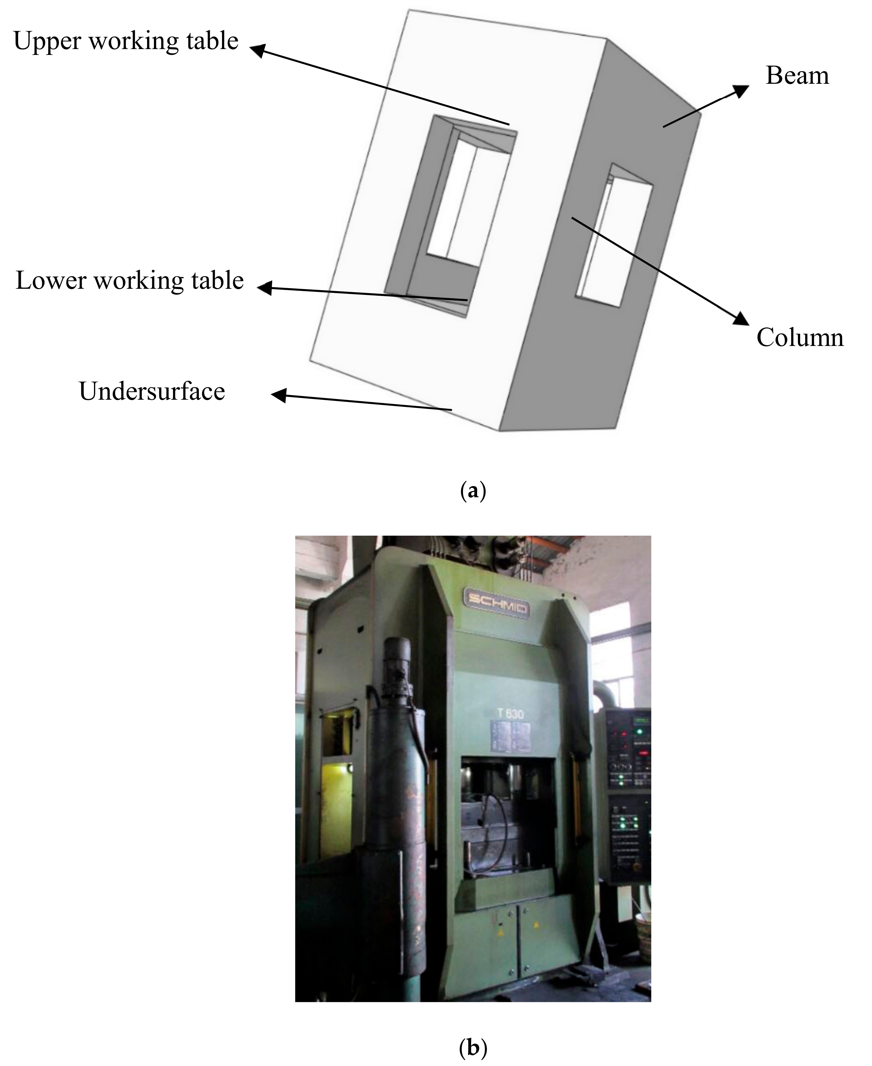
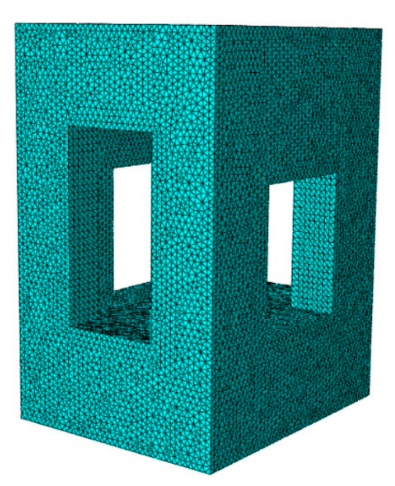
2. Static Analysis of COF Machine

The large load and high-speed stamping frequency produced in operation of the COF machine will introduce deformation of the COF machine, influence quality of the part, and reduce the life of the COF machine. It is crucial to analyze the static performance of the COF machine under nominal pressure.

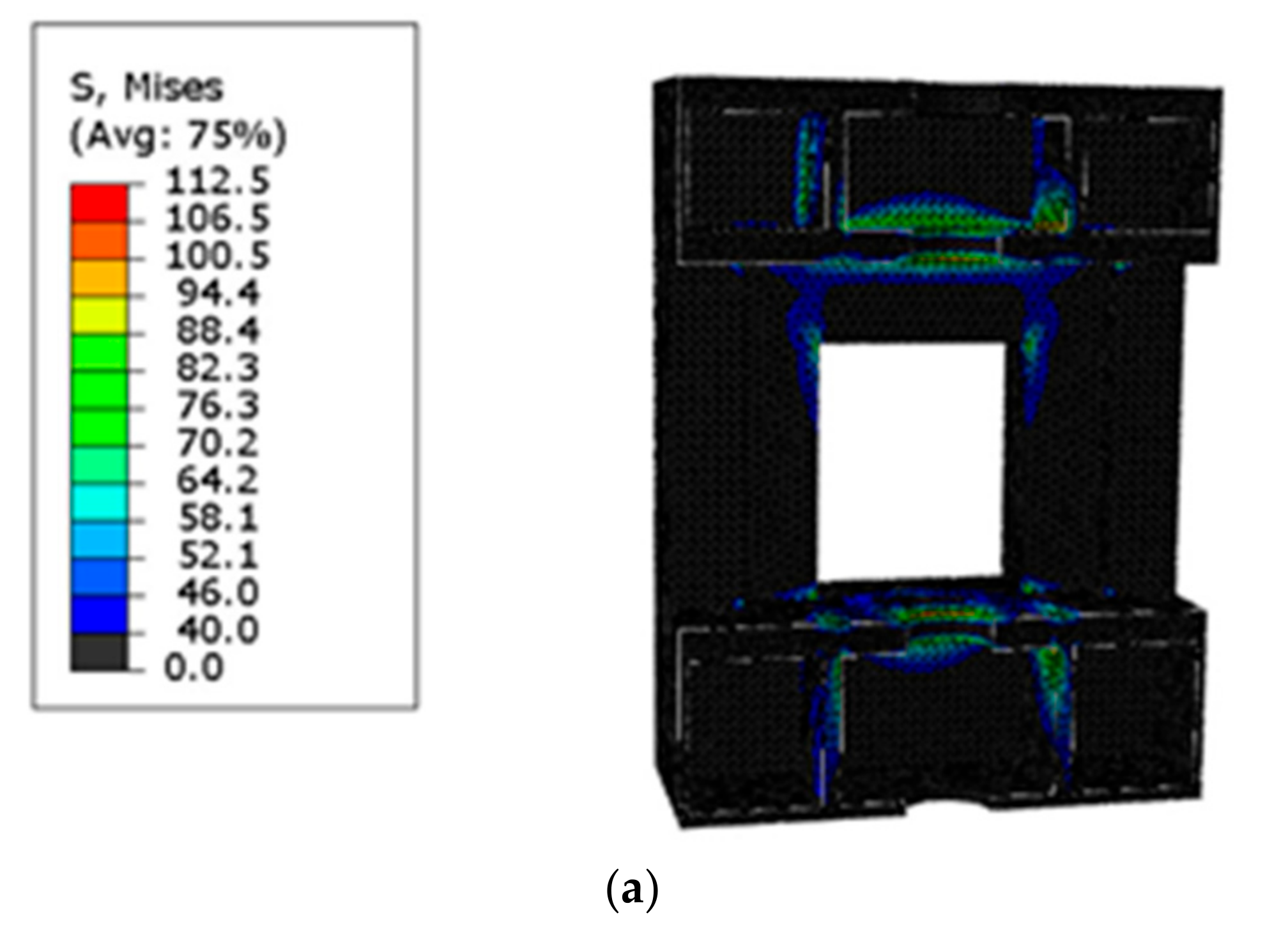
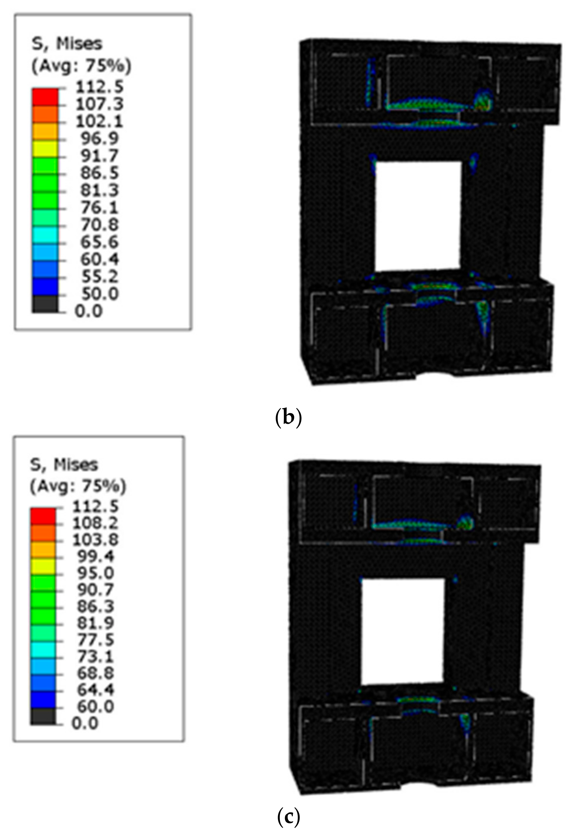
2.1. Static Stress and Displacement Analysis of the COF Machine

The structure of a 6300 KN COF machine can be seen in Figure 1. The COF machine is made of carbon structural steel (Q235). The elasticity modulus, Poisson ratio and the density of material are 210,000 MPa, 0.31 and 0.00000000785 t/mm3, respectively. The finite element mesh of the COF machine is shown in Figure 2. The mesh element type is a quadratic tetrahedral element C3D10. The total number of nodes and elements is 369,524 and 219,114, respectively.
In the COF process, the upper and lower dies contact the part directly. COF force is transferred to lower working table through the lower die. COF force is transferred to the upper working table through the upper die and the swing shaft bearing. In static performance analysis, boundary constraints and loads are shown in Figure 3. Displacement of the undersurface of the COF machine is constrained as zero displacement. The load on the COF machine is nominal pressure (6300 KN) on the COF machine, and the load is applied on upper and lower working tables.
In order to analyze the distribution of stress and displacement inside the COF machine, half of the COF machine was applied to analyze the distribution of the stress and the displacement. The equivalent stress distribution of the COF machine is shown in Figure 4.
As shown in Figure 4, the maximum equivalent stress value of the COF machine is 112.5 MPa. When plastic material suffers from static load, the value range of the safety coefficient of plastic material is 1.2–2.5. The material of the COF machine is the plastic material (16Mn) and the yield stress of 16Mn is 345 MPa. The allowable stress of the material of the COF machine can be calculated by Equation (1).
σ = σ S n = 345 2.5 = 138   MPa
where [σ] is allowable stress of material of the COF machine (MPa), σS is the yield stress of the material of the COF machine (MPa) and n is the safety coefficient of the material of the COF machine. The maximum equivalent stress value of the COF machine is less than the allowable stress of material of the COF machine.
Figure 5 shows the positions (non-black positions) where the equivalent stress is more than 40 MPa, 50 MPa and 60 MPa. In the black positions, the equivalent stress is minor and stiffness problems are less likely to exist. Large stress positions (Positions 1–6 in Figure 6) are mainly distributed near the working table and the junction between the working table and the inside of the column.
The equivalent stresses of Positions 1–6 are shown in Table 1. The equivalent stress of Position 5 is maximum in the COF machine, and the equivalent stress of Position 5 is less than the allowable stress of the material of the COF machine. Therefore, in the COF process, material yield will not take place in the COF machine. However, the equivalent stresses of Positions 1–6 are large and will reduce the quality of the part and the fatigue life of the COF machine.
The displacement of the COF machine is shown in Figure 7. Z-scale displacement of the COF machine is more obvious than the x-scale displacement and the y-scale displacement. The large displacement positions (Positions 7–10 in Figure 8) are mainly distributed near the upper and lower working tables, and the displacement of Position 8 (0.7267 mm) is the maximum in the COF machine. Large displacements of Positions 7–10 will be bad for the quality of the part and the fatigue life of the COF machine.

2.2. Static Modal Analysis of theCOF Machine

In the static modal analysis, the boundary condition of the COF machine is shown in Figure 9. Displacement of the undersurface of the COF machine is constrained as zero displacement. No other boundary constraint or load exists on the COF machine.
The first 10 orders of modal vibration of the COF machine are shown in Figure 10. In first-order and second-order modals vibrations, large x-scale displacement and large y-scale displacement exist on the COF machine. The upper and lower dies cannot be kept in alignment. The quality of the part will be affected and the dies will get worn. In third-order modal vibrations, the machine contorts around the z-axis. The forging stability of the part will be affected. In fourth-order modal vibrations, local vibration takes place on the top surface of the COF machine. In the fifth-order and sixth-order modal vibrations, x-scale displacement and y-scale displacement exist on the COF machine and the displacement is more obvious than the displacement in the first-order and second-order modal vibrations. The upper and lower dies cannot be kept in alignment. The quality of the part will be affected the and dies will get worn. In the seventh-order, eighth-order, ninth-order and tenth-order modal vibrations, local vibration occurs on the column of the COF machine. The local vibration is drastic and noise will easily happen.
The first 10 orders of modal frequency of the COF machine are 71.702 Hz, 99.525 Hz, 126.92 Hz, 324.30 Hz, 339.94 Hz, 406.92 Hz, 418.56 Hz, 422.38 Hz, 425.48 Hz and 427.77 Hz. In the COF process, the revolving speed of the swing shaft is 4 r/s, and the excitation frequency is 4 Hz. The minimum modal frequency (71.702 Hz) of the COF machine is higher than the excitation frequency. Resonance will not take place on the COF machine and the COF process is stable.

3. Dynamic Analysis of the COF Machine

The structures of the critical components of the 6300 KN COF machine can be seen in Figure 11. During the COF process, the swing shaft of the COF machine contacts the forging part. The movement of the swing shaft directly influences the forging of the part.
Figure 12 provides the structure of the swing shaft. The swing shaft consists of two cylinders and a cone; the cone represents the upper die; r04 and r05 are the radius (m) of the upper cylinder and the middle cylinder, respectively; d1, d2 and d3 are the height (m) of the upper cylinder, the middle cylinder and the cone, respectively. The total height of the swing shaft (L) can be expressed by Equation (2).
L = d 1 + d 2 + d 3
The barycenter of the swing shaft (point B3) is on the rotation axis of the swing shaft. The mass of the swing shaft (m3) can be calculated by Equation (3).
m 3 = π ρ 0 ( r 04 2 d 1 + r 05 2 d 2 + r 05 2 d 3 / 3 )
A vertical dynamic model of the swing shaft is shown in Figure 13. The vertical dynamic model is simplified as a spring-damping-mass model, and the concentrated mass is equivalent to the swing shaft. Here, k1 is the equivalent stiffness between the swing shaft and the swing shaft bearing (N/m), c1 is the equivalent damping between the swing shaft and the swing shaft bearing (N·S/m) and z3 is the vertical displacement of the swing shaft (m), of which the vertically upward direction is the positive direction of vertical displacement. The thickness of the cylindrical part after COF (h, m) can be calculated by h = h0 + z3 and h0 represents the thickness of the cylindrical part after COF, ignoring the effect of vibration (m); v is the vertical movement velocity of the forging part provided by the hydraulic system (m/s), P is the COF force (N) and T is the vertical external excitation of the swing shaft (T = Fsinωt, N).
The COF force (P) can be calculated by the following equation:
P = 10 n H S n σ σ s
where nH is the limit coefficient of the die, S is the contact area between the swing shaft and the forging part (mm2), nσ is the stress state coefficient of the contact surface between the swing shaft and the forging part and σs is the yield stress of the forging part. S and nσ can be calculated by the following:
S = 4 3 π θ 2 1 + 1 θ 3 2 π R 0 2
n σ = 1 + 0.414 1 θ + m R 0 1000 h 0.72 θ 2 + 0.591 θ + 0.0987
R0 represents the radius of the forging part (mm) and m is the friction factor of plastic deformation. The relative movement of the lower die (θ) can be calculated by Equation (7).
θ = s 2 R 0 tan γ
where s is the lower die’s movement of each turn (mm), and γ is angle between the swing shaft axis and the z axis.
In the process of elastoplastic deformation, COF force and displacement conform to the non-linear hysteresis due to the effect of periodic external excitation. The Taylor-series of P near z3 = 0 is expanded as follows:
P z 3 = P 0 + z 3 z 3 P 0 + 1 2 ! z 3 2 2 z 3 2 P 0 + 1 3 ! z 3 3 3 z 3 3 P 0 + O z 3 4
where P(0) represents the steady-state COF force and ΔP(z3) is the COF non-linear hysteretic force, which can be expressed by Equation (9).
Δ P z 3 = b 1 z 3 + b 2 z 3 2 + b 3 z 3 3
b1, b2 and b3 can be expressed by the equation below:
b 1 = z 3 P 0 b 2 = 1 2 ! 2 z 3 2 P 0 b 3 = 1 3 ! 3 z 3 3 P 0
By combining Equations (8)–(10), P can be expressed by the following equation:
P z 3 = P 0 + Δ P z 3
According to the generalized dissipation Lagrange principle, the vertical dynamic equation of the swing shaft can be expressed by Equation (12).
m 3 z ¨ 3 + c 1 z ˙ 3 + k 1 z 3 + z 0 P z 3 = T
where z0 is the equilibrium point in the COF process. In the process of steady-state COF ((T = 0), z 3 = 0, z ˙ 3 = 0, z ¨ 3 = 0), the equilibrium equation below can be obtained:
k 1 z 0 P 0 = 0
By introducing Equations (9), (11) and (13) into Equation (12), the following equation can be obtained:
m 3 z ¨ 3 + c 1 z ˙ 3 + k 1 z 3 b 1 z 3 b 2 z 3 2 b 3 z 3 3 = T
Equation (14) can be converted into Equation (15):
z ¨ 3 + ω 0 2 z 3 α z 3 2 β z ˙ 3 η z 3 3 = T 0
where ω0, α, β, η and T0 can be expressed by the following:
ω 0 = k 1 b 1 m 3 α = b 2 m 3 β = c 1 m 3 η = b 3 m 3 T 0 = T m 3 = F sin ω t m 3 = F 0 sin ω t
The parameters of 6300 KN COF machine are shown in Table 2, bringing COF machine parameters into the vertical dynamic model, so numerical simulation solutions can be obtained. Fast Fourier transform (FFT) is a kind of transformation method. FFT can transform a vertical acceleration time-domain curve into a vertical acceleration frequency-domain curve. After FFT of the vertical acceleration time-domain curve, the vertical acceleration frequency-domain curve of the swing shaft can be obtained, shown in Figure 14. As shown in Figure 14, the peak values of the frequency-domain curve of vertical vibration arise at 4 Hz and 61 Hz, and the vertical vibration of the swing shaft is a low-frequency vibration.

4. Experiment Verification

4.1. Experimental Verification of the Static Analysis

In order to verify the effectiveness of the static analysis of the COF machine, a strain test experiment with the COF machine was carried out. The strain at Positions 11–14 (Figure 15) was tested to verify the effectiveness of the static analysis.
As shown in Figure 16, a strain test experiment was carried out on a 6300 KN COF machine to verify the effectiveness of the static analysis. In the strain test experiment, the value of the initial thickness of the part was 0.05 m and the value of the radius of the forging part was 0.038 m. During the COF process, the strain of the COF machine was acquired by a strain gage and the strain signal was transmitted to the strain tester. The strain values of Positions 11–14 can be viewed and analyzed in the testing software. During the COF process, the strain values of Positions 11–14 were time-varying and the maximum strain value of each position was recorded.
The simulation strain values and the experimental strain values of Positions 11–14 are shown in Table 3. The error rates between simulation strain values and the experimental strain values were less than 10%. The static analysis of the COF machine was verified effectively.

4.2. Experimental Verification of the Dynamic Analysis

As shown in Figure 17, a verification experiment was carried out on a 6300 KN COF machine to verify the effectiveness of the dynamic model. The main equipment used for the verification experiment is shown in Table 4. In the experimental process, the angular velocities of the inner eccentric ring and the outer eccentric ring were 8π ad/s and the hydraulic system drove the forging part to move upwards. In Figure 18, a unidirectional acceleration sensor is installed on the swing shaft. The unidirectional acceleration sensor applied in the experiment was a piezoelectric unidirectional acceleration sensor (ICP). The working principle of a piezoelectric unidirectional acceleration sensor is that the embedded piezoelectric wafer is extruded by the shell mass during movement, thus generating a voltage signal. Subsequently, the voltage signal will be converted into a charge signal to achieve acceleration signal acquisition and processing. During the COF process, the vertical acceleration signal of the swing shaft is acquired by an acceleration sensor, and the vertical acceleration signal was transmitted to an LMS signal acquisition instrument. V The vertical acceleration signal of the swing shaft can be viewed and analyzed in LMS.Test.Lab software. Furthermore, in the verification experiment, it is necessary to avoid interference caused by the relative movement between the data line and the swing shaft. The data line should be a shielded line to avoid mutual interference between data lines. Meanwhile, the data line should be fixed to avoid shaking, and the data line fixed on the ground should avoid being compressed.
In LMS software, the vertical acceleration signal of the swing shaft was fast Fourier transformed. The time-domain signal of the vertical acceleration of the swing shaft was transformed to a frequency-domain signal. The experimental vertical acceleration frequency-domain curve of the swing shaft is shown in Figure 19. It can be seen that the vertical vibration of the swing shaft is a low-frequency vibration and the frequencies of vertical acceleration with high amplitude are 4 Hz and 69 Hz. If we compare Figure 19 and Figure 14, the simulation frequencies of vertical acceleration with high amplitude are very close to the experimental frequencies. The dynamic model of the COF machine is verified effectively.

5. Methods for Reducing Stress, Displacement and Vertical Vibration

5.1. Methods for Reducing Stress and Displacement

As shown in the finite element simulation results of the static analysis, large equivalent stress positions and large displacement positions are mainly distributed near the working table and the junction between the working table and the inside of the column. The large stress and large displacement of these positions are bad for the quality of the part and the fatigue life of the COF machine. In order to reduce the stress and displacement of these positions, a structural optimization method for the COF machine can be carried out.
The structural optimization method of the COF machine is shown in Figure 20. Ribbed plates were added on the working table and the beam.
In order to study the effect of the structural optimization method on the COF machine, a static simulation of the optimized COF machine was carried out. The static equivalent stress and static displacement of the optimized COF machine are shown in Figure 21. The maximum equivalent stress of the optimized COF machine (80.2 MPa) was far less than the maximum equivalent stress of the initial COF machine (112.5 MPa). The maximum displacement of the optimized COF machine (0.4268 mm) was much less than the maximum displacement of the initial COF machine (0.7267 mm). The structural optimization method of the COF machine obviously reduced the stress and displacement of the COF machine.

5.2. Methods for Reducing Vertical Vibration

As shown in the numerical simulation results of the dynamic analysis, the vertical vibration of the swing shaft was large. The large vertical vibration of the swing shaft will be bad for the quality of the part and the fatigue life of the COF machine. In order to reduce the vertical vibration of the swing shaft, an absorber was set on the swing shaft. A vertical dynamic model of the swing shaft is shown in Figure 22, where z4 is the absolute displacement of the absorber (m), k2 is the equivalent stiffness between the swing shaft and absorber (N/m), c2 is the equivalent damping between the swing shaft and absorber (N·S/m) and m4 is the equivalent mass of the absorber (kg).
According to the generalized dissipation Lagrange principle, the vertical dynamic equation of swing shaft can be expressed by Equation (17).
m 3 z ¨ 3 + c 1 z ˙ 3 + k 1 z 3 + z 0 + c 2 z ˙ 3 z ˙ 4 + k 2 z 3 z 4 P z 3 = T m 4 z ¨ 4 c 2 z ˙ 3 z ˙ 4 k 2 z 3 z 4 = 0
where z0 is equilibrium point in the COF process. In the process of steady-state COF ((T = 0), z 3 = 0, z ˙ 3 = 0, z ¨ 3 = 0), the equilibrium equation below can be obtained:
k 1 z 0 P 0 = 0
Equation (17) can be converted into Equation (19):
z ¨ 3 + ω 0 2 z 3 α z 3 2 β z ˙ 3 η z 3 3 γ z ˙ 4 δ z 4 = T 0 z ¨ 4 + ρ z ˙ 4 + σ z 4 ρ z ˙ 3 σ z 3 = 0
where ω0, α, β, η and T0 can be expressed by the following:
ω 0 = k 1 + k 2 b 1 m 3 α = b 2 m 3 β = c 1 + c 2 m 3 η = b 3 m 3 T 0 = T m 3 = F sin ω t m 3 = F 0 sin ω t γ = c 2 m 3 δ = k 2 m 3 ρ = c 2 m 4 σ = k 2 m 4
The vertical acceleration frequency-domain curve of the swing shaft is shown in Figure 23. If we compare Figure 14 and Figure 23, existence of the absorber obviously reduced the vertical vibration of the COF machine.

6. Conclusions

In this study, finite element analysis, theoretical analysis, numerical simulation and experimental analysis were applied to analyze the static performance and dynamic performance of the COF machine. The static and dynamic analyses were verified effectively by carrying out strain and vertical vibration test experiments of a 6300 KN COF machine. In the static and dynamic analyses of the COF machine, large stress positions, large displacement positions and vertical vibration performance are explicit. According to the large stress positions and large displacement positions of the COF machine, a structural optimization method for the COF machine was put forward to reduce stress and displacement. Based on the vertical dynamic model, an absorber was set to reduce vertical vibration. Several conclusions can be drawn as follows:
In the static analysis, the large stress positions of the COF machine were mainly distributed near the working table and the junction between the working table and the inside of the column. The large displacement positions were mainly distributed near upper and lower working tables. The maximum equivalent stress of the COF machine was less than the allowable stress of the material of the COF machine. In the COF process, material yield will not take place in the COF machine. However, large stress and displacement positions will be bad for the quality of the part and the fatigue life of the COF machine. In order to reduce the stress and displacement of these positions, structural optimizations of the COF machine was conducted. The structural optimization of the COF machine involved ribbed plates on the working table and the beam. The structural optimization of the COF machine obviously reduced the stress and displacement of the COF machine.
In the dynamic analysis, when the angular velocities of the inner and outer eccentric ring were 8π rad/s, the peak values of the frequency-domain curve of vertical vibration arose a t4 Hz and 61 Hz and the vertical vibration of the swing shaft was a low-frequency vibration. The frequency interval between the two peaks of the frequency-domain curve of vertical vibration was larger, the vertical vibration of the swing shaft was relatively stable. However, the vertical vibration of the swing shaft will be bad for the quality of the part and the fatigue life of the COF machine. In order to reduce the vertical vibration of the swing shaft, the absorber was set up on the swing shaft. The existence of the absorber obviously reduced the vertical vibration of the COF machine.
In this study, static performance and dynamic performance were analyzed and methods were put forward for reducing the stress, displacement and vertical vibration of the COF machine. The investigations in this paper contribute to improving the quality of the part and the fatigue life of the COF machine.

Author Contributions

Z.G.: investigation, supervision, writing—original draft preparation. M.C.: methodology, resources, writing—review and editing. C.W.: writing—review and editing. W.Z.: funding acquisition, writing—review and editing. All authors have read and agreed to the published version of the manuscript.

Funding

The authors would like to thank the National Natural Science Foundation of China (No. 51575416), the National Natural Science Foundation of China Youth Fund (52005375), the Independent Innovation Foundation of Wuhan University of Technology (2019IVA102) and the China Postdoctoral Science Foundation (2020M672429) for the support given to this research.

Conflicts of Interest

The authors declare no conflict of interest.

References

  1. Han, X.; Hua, L.; Zhuang, W.; Zhang, X. Process design and control in cold rotary forging of non-rotary gear parts. J. Mater. Process. Technol. 2014, 214, 2402–2416. [Google Scholar] [CrossRef]
  2. Jiao, M.; Guo, X.H.; Wan, D.D. Finite element analysis and lightweight research on the bed of a large machine tool based on HyperWorks. Appl. Mech. Mater. 2011, 121–126, 3294–3298. [Google Scholar] [CrossRef]
  3. Zou, H.; Wang, B.; Song, F.; Fu, L. The application of mineral casting in high-precision printed circuit board drilling machine. Circuit World 2013, 39, 204–211. [Google Scholar] [CrossRef]
  4. Markowski, T.; Mucha, J.; Witkowski, W. FEM analysis of clinching joint machine’s C-frame rigidity. Eksploat. Niezawodn.-Maint. Reliabi. 2013, 15, 51–57. [Google Scholar]
  5. Syam, W.P.; Jianwei, W.; Zhao, B.; Maskery, I.; Elmadih, W.; Leach, R. Design and analysis of strut-based lattice structures for vibration isolation. Precis. Eng. J. Int. Soc. Precis. Eng. Nanotechnol. 2018, 52, 494–506. [Google Scholar] [CrossRef]
  6. Irfan, S.; Siddiqui, F. A review of recent advancements in finite element formulation for sandwich plates. Chin. J. Aeronaut. 2019, 32, 785–798. [Google Scholar] [CrossRef]
  7. Gohari, S.; Sharifi, S.; Sharifishourabi, G.; Vrcelj, Z.; Abadi, R. Effect of temperature on crack initiation in gas formed structures. J. Mech. Sci. Technol. 2013, 27, 3745–3754. [Google Scholar] [CrossRef]
  8. Sherbakov, S.S. Three-Dimensional Stress-Strain State of a Pipe with Corrosion Damage under Complex Loading. In Tribology-Lubricants and Lubrication; BoD–Books on Demand: Norderstedt, Germany, 2011. [Google Scholar]
  9. Sherbakov, S.S.; Zhuravkov, M.A. Interaction of several bodies as applied to solving tribo-fatigue problems. Acta Mech. 2013, 224, 1541–1553. [Google Scholar] [CrossRef]
  10. Shcherbakov, S.S. Spatial stress-strain state of tribofatigue system in roll-shaft contact zone. Srength Mater. 2013, 45, 35–43. [Google Scholar] [CrossRef]
  11. Sherbakov, S.S. Measurement and real time analysis of local damage in wear-and-fatigue tests. Devices Methods Meas. 2019, 10, 207–214. [Google Scholar] [CrossRef] [Green Version]
  12. Sosnovskiy, L.A.; Sherbakov, S.S. On the development of mechanothermodynamics as a new branch of physics. Entropy 2019, 21, 1188. [Google Scholar] [CrossRef] [Green Version]
  13. Li, B.; Cai, H.; Mao, X.; Huang, J.; Luo, B. Estimation of CNC machine-tool dynamic parameters based on random cutting excitation through operational modal analysis. Int. J. Mach. Tools Manuf. 2013, 71, 26–40. [Google Scholar] [CrossRef]
  14. Liu, F.; Liu, B.; Liu, H.R.; Gong, Y.L.; Wang, S.J. Vertical vibration of strip mill with the piecewise nonlinear constraint arising from hydraulic cylinder. Int. J. Precis. Eng. Manuf. 2015, 16, 1891–1898. [Google Scholar] [CrossRef]
  15. Bar, A.; Swiatoniowski, A. Interdependence between the rolling speed and non-linear vibrations of the mill system. J. Mater. Process. Technol. 2004, 155–156, 2116–2121. [Google Scholar] [CrossRef]
  16. Lu, X.; Sun, J.; Li, G.; Wang, Q.; Zhang, D. Dynamic analysis of vibration stability in tandem cold rolling mill. J. Mater. Process. Technol. 2019, 272, 47–57. [Google Scholar] [CrossRef]
  17. Lu, X.; Sun, J.; Li, G.; Wang, Z.; Zhang, D. Stability analysis of a nonlinear coupled vibration model in a tandem cold rolling mill. Shock Vib. 2019, 2019, 4358631. [Google Scholar] [CrossRef]
  18. Kim, Y.; Kim, C.W.; Lee, S.; Park, H. Dynamic modeling and numerical analysis of a cold rolling mill. Int. J. Precis. Eng. Manuf. 2013, 14, 407–413. [Google Scholar] [CrossRef]
  19. Kim, Y.; Kim, C.W.; Lee, S.J.; Park, H. Experimental and numerical investigation of the vibration characteristics in a cold rolling mill using multibody dynamics. ISIJ Int. 2012, 52, 2042–2047. [Google Scholar] [CrossRef] [Green Version]
  20. Zhao, X.; Liu, Y.; Hua, L.; Mao, H. Finite element analysis and topology optimization of a 12000KN fine blanking press frame. Struct. Multidiscip. Optim. 2016, 54, 375–389. [Google Scholar] [CrossRef]
  21. Li, C.; Kim, I.Y.; Jeswiet, J. Design space and detailed design of an automotive engine cradle by using topology, shape, and size optimization. Struct. Multidiscip. Optim. 2015, 51, 547–564. [Google Scholar] [CrossRef]
  22. Strano, M.; Monno, M.; Rossi, A. Optimized design of press frames with respect to energy efficiency. J. Clean Prod. 2013, 41, 140–149. [Google Scholar] [CrossRef]
  23. Duan, Z.D.; Wu, J.J. Topological Optimization of Frame of High Speed Hydraulic Press Based on Generalized Finite Element Modules. Appl. Mech. Mater. 2010, 44–47, 1828–1832. [Google Scholar] [CrossRef]
  24. Xu, D.K.; Chen, J.; Tang, Y.C.; Cao, J. Topology optimization of die weight reduction for high-strength sheet metal stamping. Int. J. Mech. Sci. 2012, 59, 73–82. [Google Scholar] [CrossRef]
  25. Yan, Y.N.; Jing, H.; Zhang, D.J.; Chen, Z.D.; Huang, X.F. Optimization design of heavy load-bearing frame–Discussing about the 1200MN hydraulic press: I. Forg. Stamp. Technol. 2013, 38, 1–13. [Google Scholar]
  26. Han, X.H.; Hua, L. 3D FE modelling of contact pressure response in cold rotary forging. Tribol. Int. 2013, 57, 115–123. [Google Scholar] [CrossRef]
  27. Han, X.; Hu, Y.; Hua, L. Cold orbital forging of gear rack. Int. J. Mech. Sci. 2016, 117, 227–242. [Google Scholar] [CrossRef]
  28. Oudin, J.; Ravalard, Y.; Verwaerde, G.; Gelin, J.C. Force, torque and plastic flow analysis in rotary upsetting of ring shaped billets. Int. J. Mech. Sci. 1985, 27, 761–780. [Google Scholar] [CrossRef]
  29. Canta, T.; Frunza, D.; Sabadus, D.; Tintelecan, C. Some aspects of energy distribution in rotary forming processes. J. Mater. Process. Technol. 1998, 80, 195–198. [Google Scholar] [CrossRef]
  30. Han, X.H.; Zhang, X.C.; Hua, L. Calculation method for rocking die motion track in cold orbital forging. J. Manuf. Sci. Eng. 2016, 138, 014501. [Google Scholar] [CrossRef]
  31. Han, X.H.; Zhang, X.C.; Hua, L. Calculation of kinetic locus of upper tool in cold orbital forging machine with two eccentricity rings. J. Mech. Sci. Technol. 2015, 29, 4351–4358. [Google Scholar] [CrossRef]
  32. Feng, W.; Yao, W.; Jiang, P. Influence of eccentricity on movements of orbital head with double eccentric structure in orbital forging. Procedia Eng. 2014, 81, 2348–2354. [Google Scholar] [CrossRef] [Green Version]
  33. Dong, L.; Han, X.; Hua, L.; Lan, J.; Zhuang, W. Effects of the rotation speed ratio of double eccentricity bushings on rocking tool path in a cold rotary forging press. J. Mech. Sci. Technol. 2015, 29, 1619–1628. [Google Scholar] [CrossRef]
Figure 1. Structure (a) and equipment (b) of the 6300 KN cold orbital forging (COF) machine.
Processes 09 00007 g001
Figure 2. Finite element mesh of the COF machine.
Processes 09 00007 g002
Figure 3. Boundary conditions of the COF machine.
Processes 09 00007 g003
Figure 4. Equivalent stress distribution of the COF machine.
Processes 09 00007 g004
Figure 5. Positions where the equivalent stress is more than 40 MPa (a), 50 MPa (b) and 60 MPa (c).
Processes 09 00007 g005aProcesses 09 00007 g005b
Figure 6. Large stress positions of the COF machine.
Processes 09 00007 g006
Figure 7. Main displacement (a), x-scale displacement (b), y-scale displacement (c) and z-scale displacement (d) of the COF machine.
Processes 09 00007 g007
Figure 8. Large displacement positions of the COF machine.
Processes 09 00007 g008
Figure 9. Boundary condition of the COF machine.
Processes 09 00007 g009
Figure 10. First 10 orders of modal vibrations of the COF machine.
Processes 09 00007 g010aProcesses 09 00007 g010b
Figure 11. Structures of the critical components of the 6300 KN COF machine.
Processes 09 00007 g011
Figure 12. Structure of the swing shaft.
Processes 09 00007 g012
Figure 13. Vertical dynamic model of the swing shaft.
Processes 09 00007 g013
Figure 14. Vertical acceleration frequency-domain curve of the swing shaft.
Processes 09 00007 g014
Figure 15. Positions of strain test.
Processes 09 00007 g015
Figure 16. Strain test experiment.
Processes 09 00007 g016
Figure 17. Verification experiment of the dynamic model.
Processes 09 00007 g017
Figure 18. Installation site of the unidirectional acceleration sensor.
Processes 09 00007 g018
Figure 19. Vertical acceleration frequency-domain curve of the swing shaft.
Processes 09 00007 g019
Figure 20. Initial structure (a) and optimized structure (b) of the COF machine.
Processes 09 00007 g020
Figure 21. Static equivalent stress (a) and static displacement (b) of the optimized COF machine.
Processes 09 00007 g021aProcesses 09 00007 g021b
Figure 22. Vertical dynamic model of the swing shaft.
Processes 09 00007 g022
Figure 23. Vertical acceleration frequency-domain curve of the swing shaft.
Processes 09 00007 g023
Table 1. Equivalent stresses of Positions 1–6.
Position Number123456
Equivalent stress108.067 MPa98.219 MPa93.036 MPa104.176 MPa112.521 MPa105.080 MPa
Table 2. Parameters of the 6300 KN COF machine.
ParameterValue
Upper cylinder radius of the swing shaft (r04, m)0.105
Middle cylinder radius of the swing shaft (r05)0.2625
Upper cylinder height of the swing shaft (d1, m)0.805
Middle cylinder height of the swing shaft (d2, m)0.245
Cone height of the swing shaft (d3, m)0.0875
Density of steel (ρ0, kg/m3)7900
Equivalent stiffness (k1, N/m)9.763 × 107
Equivalent damping (c1, N·S/m)1.073 × 104
Table 3. Comparison between the simulation strain values and the experimental strain values of the COF machine.
Position Number11121314
Simulation value0.000147 0.000132 0.000034 0.000035
Experimental value0.000153 0.0001410.000031 0.000037
Error rate4.08%6.81%−8.82%5.71%
Table 4. Main equipment used for the verification experiment.
EquipmentTypeQuantity
Acceleration sensorPiezoelectric unidirectional acceleration sensor1
Data lineShielded line10
Signal acquisition instrumentLMS signal acquisition instrument1
ComputerComputer installed with LMS.Test.Lab software1
Auxiliary equipmentDesk, paper and pen1
Publisher’s Note: MDPI stays neutral with regard to jurisdictional claims in published maps and institutional affiliations.

