Review

Advanced 3D Cell Culture Techniques in Micro-Bioreactors, Part II: Systems and Applications

1
Department of Prosthetic Dentistry, Center for Dental Medicine, Medical Center—University of Freiburg, Faculty of Medicine, University of Freiburg, 79106 Freiburg, Germany
2
G.E.R.N Center for Tissue Replacement, Regeneration & Neogenesis, Department of Prosthetic Dentistry, Medical Center—University of Freiburg, Faculty of Medicine, University of Freiburg, 79108 Freiburg, Germany
3
Institute of Functional Interfaces, Group 3D Cell Culture Systems, Karlsruhe Institute of Technology, 76021 Karlsruhe, Germany
*
Author to whom correspondence should be addressed.
Processes 2021, 9(1), 21; https://doi.org/10.3390/pr9010021
Submission received: 31 October 2020 / Revised: 18 December 2020 / Accepted: 21 December 2020 / Published: 23 December 2020
(This article belongs to the Section Biological Processes and Systems)

Abstract

:
In this second part of our systematic review on the research area of 3D cell culture in micro-bioreactors we give a detailed description of the published work with regard to the existing micro-bioreactor types and their applications, and highlight important results gathered with the respective systems. As an interesting detail, we found that micro-bioreactors have already been used in SARS-CoV research prior to the SARS-CoV2 pandemic. As our literature research revealed a variety of 3D cell culture configurations in the examined bioreactor systems, we defined in review part one “complexity levels” by means of the corresponding 3D cell culture techniques applied in the systems. The definition of the complexity is thereby based on the knowledge that the spatial distribution of cell-extracellular matrix interactions and the spatial distribution of homologous and heterologous cell–cell contacts play an important role in modulating cell functions. Because at least one of these parameters can be assigned to the 3D cell culture techniques discussed in the present review, we structured the studies according to the complexity levels applied in the MBR systems.

1. Introduction

In part I of the review, we systematically analyzed the work published between 2000 and 2020 in the field of 3D cell culture in micro-bioreactors (MBRs), which were developed for growing mammalian cells and/or tissues in vitro on a smaller scale when compared to large-scale bioreactors for biotechnological applications and industrial production. Starting from such small-scale bioreactor approaches, MBRs have become important tools in 3D cell culture which prevail today as a specialized bioreactor group in the field of biomedical research. The main aspects in the first part of the review were the MBR design, the corresponding 3D cell culture techniques and the related cellular microenvironment, the mode of cell stimulation and/or nutrient supply, the materials used for MBRs and scaffold fabrication, the applications of the systems and the used cell type or in vitro-model. For this, we used the following key search terms in the PubMed® database of the National Library of Medicine of the National Center for Biotechnology Information (NCBI):
  • “3D cell culture” AND “microbioreactor”
  • (bioreactor OR microbioreactor OR micro-bioreactor) AND (“three-dimensional cell culture” OR “3D cell culture” OR “3-D cell culture”)
  • (microbioreactor OR micro-bioreactor) AND “tissue engineering”
According to our literature analysis in the first part, application areas of MBR systems for 3D cell and/or tissue culture involve mainly the research fields of in-vitro models, tissue engineering and high-throughput-screening. In this context, our literature research revealed that characteristic features of most MBR systems are (i) a low volume of culture medium (less than 500 mL), (ii) an active fluid flow, being realized by a pump, a stirring mechanism, piston movements or mechanical movement of the cell-based constructs in culture medium, and (iii) in some systems the use of scaffolds (see also review part I in this issue).
In this second part of the review, we give a detailed description of the results of our literature research with regard to the existing MBR types and their applications, as well as on common cell/tissue types cultured in such systems. As our literature research revealed a variety of 3D cell culture configurations in the MBR systems, in part I of the review we defined “complexity levels” by means of the corresponding 3D cell culture techniques used in the MBRs. The complexity levels are depicted in Figure 1 and are defined as follows:
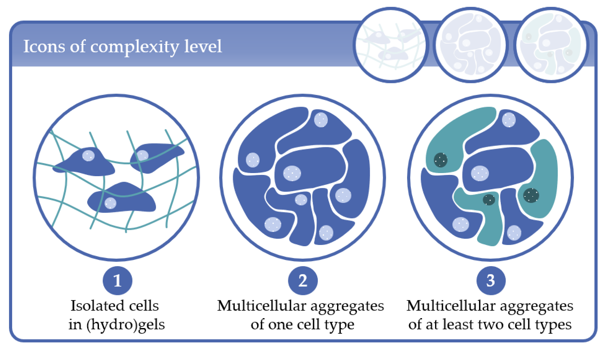
  • Complexity level 1: cells immobilized in (hydro)gels as mono-culture (one cell type) or co-culture (at least two cell types);
  • Complexity level 2: multicellular aggregates consisting of one cell type in 3D scaffolds or in scaffold-free cultures;
  • Complexity level 3: multicellular aggregates consisting of at least two cell types in 3D scaffold-based or in scaffold-free cultures.
The definition and organization of the complexity levels are based on the knowledge that the spatial distribution of cell–extracellular matrix (ECM) interactions and the spatial distribution of homologous and heterologous cell–cell contacts modulate, among other parameters, the cell behavior. Because at least one of these parameters can be assigned to the 3D cell culture techniques discussed in the present review, we structured the studies according to the complexity levels applied in the MBR systems for better clarity. As already discussed in review part I, the approaches applied to generate such 3D cell constructs in vitro can be further subdivided in scaffold-based and scaffold-free techniques (see also review part I in this issue). For a detailed overview of the 3D cell culture configurations, fluid flow modes and the main MBR types which are discussed in detail in the present review, the reader is referred to review part I.
Because many custom abbreviations are used, we have included a table (Table 1) that summarizes the used abbreviations of the paper.

2. Complexity Level 1: Isolated Cells in (Hydro)Gels

The immobilization of tissue-specific cells in (hydro)gels and their subsequent implantation into damaged tissues or organs is one of the first attempts in tissue engineering (TE) to regenerate damaged tissue and dates back to the early 1980s. The implanted cells were supposed to fulfill the secretory, structural or barrier- and transport-function of the damaged tissue. Examples of target tissues and organs were liver, pancreas, cartilage, skin and blood vessels. The gel-based cell scaffolds represented a closed system that protected the implanted cells against the immune system of the host, allowed the mass transfer of nutrients and metabolites by diffusion and enabled the long-term secretion of signaling molecules from the implanted cells into the surrounding tissue [1]. The first bioreactor systems used for the expansion and proper in vitro-morphogenesis of the engineered tissues included in this context mainly spinner flasks and stirred tank systems, and tubular perfusion systems specifically designed for vessel culture, respectively [1,2,3,4,5] (for the definition of perfusion culture see also review part I, in this issue). One important finding of these early works was that mechanical forces appeared to be another key parameter that modulates the cell behavior in addition to the 3D organization of the ECM and growth factors, and by this determines the quality of the engineered cell/tissue constructs.

2.1. Early MBR Designs in Complexity Level 1

From 2000 onwards, several research groups developed bioreactor systems to systematically investigate the effect of mechanical forces on cell functions and/or tissue morphogenesis to improve the mechanical and morphological properties of tissue engineered in vitro-constructs [6,7,8,9] (Figure 2). The primary aim of bioreactor design was then to mimic the geometry and/or the nature of the mechanical stimuli of the target tissue, e.g., mechanical strains, stretch and pulsatile flow. Thus, as diverse as the different tissue types are, so were the approaches. In detail, bioreactors designed for the application of ligament-like multidimensional mechanical strains, e.g., translational and rotational strain [6] (Figure 2A), or repetitive muscle-like stretch and relaxation of the gel-based constructs [7], enabled the fixation of pre-cultured cell/gel constructs and the mechanical stimulation of the cells by controlled displacement of the anchor points. In this way, Altman et al. [6] proved that mechanical stimuli were able to support the selective differentiation of bone marrow cells towards ligament-like cells in the absence of specific growth/differentiation factors. One year later, Powell et al. [7] revealed that repetitive stretch/relaxation of human muscle cells immobilized in collagen/Matrigel® increased the biomechanical and morphological properties of such bioartificial muscles. With respect to tissue engineered vascular grafts, Hahn et al. [8] developed a pulsatile flow bioreactor which allowed for physiological shear and pulsatile conditioning of such vascular in vitro-constructs. The system included a closed circulation loop with pumps generating a pulsatile flow, a custom graft chamber, a medium reservoir and a peristaltic pump (Figure 2B). The vascular constructs consisted of mouse smooth muscle progenitor cells encapsulated within polyethylene glycol (PEG)-based hydrogels which contained adhesive ligands and collagenase degradable sequences. In order to prepare perfusable vascular constructs with a lumen of about 3 mm, the cell/gel mixture was first pipetted in cylindrical molds fitted with inner glass mandrels. The polymerized constructs were then fixed at the ends of a custom glass chamber and pre-cultured under static conditions in the bioreactor before mechanical fluid flow stimulation. The preparation of the gel-based cell constructs under static conditions, prior to the integration into the bioreactors, was a common approach in these works and pre-culture time varied between 24 h and 1 week. A microfluidic MBR setup was also applied by Moretti et al. [10] to stimulate bovine chondrocytes with hydrodynamic shear stress and/or hydrostatic pressure in a non-woven hyaluronan scaffold. The results of this study demonstrated that the combination of hydrostatic pressure and perfusion was superior to static and perfusion cultures in terms of cellular metabolic activity. Wilkes et al. [9] in turn presented an approach exploring the biological effect of a clinically established wound therapy using vacuum-assisted negative pressure, or more generally, the impact of mechanical stimulation by ECM compression on cell response. In contrast to the aforementioned studies, the bioreactor culture used here was not intended to generate improved tissue engineered constructs by means of biomechanical stimulation of the cells but rather to establish an in vitro-model for fundamental research on the effect of subatmospheric pressure application to tissue in general. The bioreactor system consisted of commercially available cell culture inserts with associated 6-well plates as a cell culture platform, combined with several sealing rings and syringe needles to create self-sealing ports for media injection (perfusion culture) and negative pressure application. Tissue analogues were prepared by immobilizing adult human dermal fibroblasts in fibrin clots and pre-culturing of the cells until they reached 50% to 70% confluence. For the mechanical stimulation of the cells, the fibrin clots were covered by commercially available negative pressure dressings which provided a flexible, pneumatic barrier over the wound model. With this experimental approach the authors demonstrated that subatmospheric pressure resulted in fibrin matrices with characteristic geometry similar to that observed in clinical application, and induced morphological changes on a cellular level which were characterized by thicker cell bodies and denser cytoskeleton compared to unstimulated cells. The impact of mechanical cues on cell morphology and the cytoskeleton was later confirmed by a growing number of other studies, and has gained in importance to date in biomedical research.
Further critical issues in the TE field at that time were the nutrient and gas supply of the encapsulated cells in the bioreactor systems to ensure the generation of vital and larger tissue engineered in vitro-constructs, and to gain a better understanding of how to control cell behavior with respect to stem cell differentiation and the maintenance of the tissue-specific phenotype of mature cells [1,12,13]. In this context, another research focus in MBR design was the improvement of mass transfer and the creation of a well-defined, homogenous cell culture environment. With respect to mass transfer, technical approaches included the cultivation of encapsulated cells as mono- or co-cultures in MBRs with perfusion chambers in a closed medium circulation loop [14] (Figure 3) or in a rotating cell culture microgravity bioreactor (high aspect ratio vessel (HARV) [15]. The latter was already developed in 1983 by Briegleb [16] to enable an optimal nutrient supply under low shear stress conditions and will be described in more detail in Section 3.
Aiming at the improvement of the concept of a defined 3D cell microenvironment in terms of a homogenous mass transfer, Wu et al. [17] presented a microfluidic perfusion MBR which applied the concept of miniaturization to 3D cell culture. The system consisted of two polydimethylsiloxane (PDMS) layers, one containing flow channels and the other the associated culture chamber (Figure 4A).
The microfluidic platform included five MBRs with 7 mm diameter each; containing the chondrocyte/agarose-based constructs. To assemble the system, the chondrocyte/agarose suspension was immediately loaded into each culture chamber which was subsequently closed by fitting the two PDMS slabs together (flow channel and culture chamber layers). Distinctive for this approach when compared to the aforementioned systems were (1) the integration of the miniaturization and parallelization concept into the bioreactor design and (2) the elimination of the preparation and pre-culture of the gel-based constructs outside the system. This culture system was then further downscaled to 12 MBRs on one platform organized in a parallel manner and with an individual medium supply of each bioreactor by a peristaltic pump or a number of syringe pumps [18] (Figure 4B). Within the scope of this work, Cui et al. [18] examined the applicability of the modified system for drug evaluation and toxicity testing by analyzing the cell response of human bone marrow cells (hBMCs) immobilized in collagen-I-/Matrigel® scaffolds. Only one year later, another modification and further development of the system was presented by Wu et al. [19]. Here, the platform was downscaled again to 30 MBRs which were now supplied by S-shape pneumatic micropumps connected to a pneumatic tank and microchannels for medium flow and cell/agarose loading. In contrast to the first prototype presented in 2006, cell loading of the present system was now performed via microchannels in the fully assembled culture platform (Figure 4C). A different strategy to fabricate gel-based microfluidic devices was pursued by Ling et al. [20] who generated the microfluidic channels by molding the cell laden agarose gels into patterned silicon wafers (Figure 5A), or by Chang et al. [21] through a direct cell writing bioprinting process of alginate encapsulated cells into glass etched channels of the MBR device (Figure 5B). In both cases, the cell-laden gels were filled into a shaping structure of the microfluidic device and thus rendered the external cell loading of the system, as described above in the works of Wu and colleagues, unnecessary.
To summarize, it can be stated that during the first decade of the 21st century one initial focus in MBR design for gel-based cell culture applications was the generation of optimized tissue engineered in vitro-constructs for clinical applications. However, based on these works and the gathered knowledge on the impact of the microenvironment on cell functions, in vitro-models for fundamental research were increasingly getting into focus. Important aspects of bioreactor design, besides biomechanical cues, were the generation of a defined cellular 3D microenvironment, and the miniaturization and parallelization of the 3D culture for high-throughput capability in analogy to the already established 2D monolayer cultures in 96 well format.

2.2. Latest MBR Developments in Complexity Level 1

After 2010, research in this field was mainly characterized by the optimization of the established systems with respect to improved nutrient supply, cell seeding techniques and biomechanical stimulation. As already described above, bioreactor design for specific mechanical stimulation of tissue constructs was first based on the tissue geometry and on locally occurring forces. This concept was further developed in the following years especially in the field of cartilage TE. In detail, Schätti et al. [22] presented a system capable to combine cyclic compressive forces and shear forces to stimulate human mesenchymal stem cells (hMSCs) in a fimbrin matrix integrated in porous polyurethane (PU) scaffolds. The system followed the earlier design presented by Wimmer et al. [23] consisting of a ceramic ball which was pressed onto the scaffold. Compressive strain and interface shear motion were generated by compression of the scaffold and simultaneous oscillation of the ball. This system was later used as an in vitro-test system for the evaluation of a new hydrogel-based biomaterial for MSC-based cartilage repair [24]). In 2012, Gharravi et al. [25] presented a bioreactor consisting of a cell culture chamber capable to house different culture configurations, i.e., chondrocytes in alginate hydrogel beads, alginate hydrogel sheets and alginate hydrogel molds, and a motorized piston which could be moved vertically on the gel-based constructs. In this way, both studies demonstrated that the generated biomechanical cues were able to increase the expression of chondrogenic biomarkers in hMSCs and to maintain the mature phenotype of chondrocytes, respectively. A different approach in the biomechanics context was taken by Correia et al. [26] who designed two bioreactors suitable for the application of high (up to 10 MPa) and low (up to 0.5 MPa) hydrostatic pressure on human nasal chondrocytes (HNCs) or human adipose stem cells (hASCs) encapsulated in gellan gum hydrogels. The low-pressure bioreactor was designed relatively simple and consisted of a 30 mL-Luer-Lock polypropylene syringe, where the rubber piston is used to exert pressure on the cell constructs in the syringe. The high-pressure bioreactor consisted of a stainless-steel device culture chamber which was integrated in a closed circulation loop for permanent culture medium exchange. The compressive force was generated via a compressed air-driven piston. The concept of tissue adopted bioreactor design is employed till today in the TE field as demonstrated in a recent work by Lee et al. [11]. Here, cruciform-shaped collagen gels with fibroblasts were used as a soft tissue model for biomechanical studies (Figure 2D). The gels were prepared and pre-cultured for 24h under static conditions and subsequently integrated into a biaxial actuator system. The mechanical stimulation occurred in analogy to the 2D Flexcell® tension system by the defined biaxial stretch of the cruciform shaped gels.
Unlike aforementioned approaches using compression or stretch of the 3D cell constructs, Santoro et al. [27] cultured human articular chondrocytes seeded in mesh-like scaffolds in a perfusion bioreactor system to generate human cartilage grafts with clinically relevant cell density and size. Further approaches using (hydro)gel-based cell cultures address tumor modelling in the field of preclinical in vitro cancer research. In this context, Jaeger et al. [28] established synthetic vessels made from oxygen-permeable silicone hydrogel membranes containing arrays of micropillars. The membranes were surrounded by basement membrane extract with ovarian cancer cells and inserted into a custom-made bioreactor to examine the role of oxygen tension gradients on tumor growth in gel-embedded cells. In another study, Sriram et al. [29] used a bioreactor compatible with hyperpolarized 13C magnetic resonance to investigate the role of lactate efflux as a biomarker of cancer aggressiveness. The bioreactor setup comprised a perfusion chamber which was suitable to culture immobilized cells in alginate microspheres or tissue slices derived from patients.
With respect to high-throughput-screening (HTS), several works on the technical improvement of the previously described MBR system established by the work groups around Wu and Cui have been published after 2010. The main focus was here the further increase of MBR units on one platform (Figure 6A), the optimization of the cell/hydrogel loading mechanism, the integration of a “plug module” to facilitate the preparation of cell encapsulated 3D hydrogel constructs (Figure 6B), the integration of a heater chip for stable thermal conditions during cell culture, of a waste medium collector module which could be combined with a plate reader for subsequent bioassays (Figure 6C) and the integration of novel micropumps for the corresponding functions [30,31,32]. Applications of this MBR system focused on cell-based assays in the context of new biomaterial evaluation [33] and drug chemosensitivity assay [34].
Further approaches in this HTS context were presented by Moraes et al. [35] and Pagano et al. [36]. Moraes and his colleagues focused on the biomechanical stimulation of mouse MSCs in poly(ethylene glycol) hydrogels which were injected into a PDMS device consisting of 25 vertically actuated loading posts and related cavities housing the cell laden gels (Figure 7A). Hence, for the first time this system specifically combined mechanical compressive loading with an HTS concept, i.e., miniaturization and parallelization (Figure 7A). Pagano et al. designed an MBR with one central channel containing the cell laden hydrogel, and two identical channels, juxtaposed to the lateral edges of the hydrogel for the medium flow (Figure 7B) [36]. The central and side channels were divided by an array of S-shaped micropillars which allow the formation and maintenance of a stable concentration gradient of molecules for chemotaxis experiments (Figure 7B). In the context of TE, Goldman et al. [37] integrated microfluidic networks in chondrocyte/agarose gels by casting the agarose solution between an acrylic casing and a PDMS mold (Figure 7C). For an active perfusion of the gel, the MBR device housing the constructs were connected to medium flow loops equipped with a syringe pump with dual check valves to generate unidirectional flow through the microchannels. The aim of this work was to enhance proliferation and biosynthesis of ECM components by improved nutrient transport through the gel, and by this to generate in vitro-constructs with a clinically relevant thickness and robustness for articular cartilage TE. Another approach to generate tissue engineered constructs for cell-based therapies was to entrap MSCs derived from the periodontal ligament in alginate microbeads and to culture them in a Rotary Cell Culture System (RCCS), also known as the rotating wall vessel system, which is described in the following section. The 3D dynamic conditions provided by the bioreactor increased the osteogenic potential of the MSCs and appeared, according to the authors, as an appropriate method to generate 3D constructs applicable for treatment of oral bone defects [38]. In contrast to the described microfluidic systems, Rödling et al. [39] presented magnetic cell-laden hydrogels for contactless movement of the gel-based constructs by an external magnetic field (Figure 7D). The underlying idea of this approach is to perfuse 3D scaffolds in a contactless manner without the use of pumps or custom-made accessories, and by this, to run dynamic cultures in conventional, relatively inexpensive ready-to-use disposable cell culture tubes which may facilitate the maintenance of sterility and the parallelization of the setup.
In conclusion, MBR design for gel-based 3D scaffolds in the TE field still remains manifold and primarily addresses the application of mechanical forces on the target cells to improve the function of tissue engineered constructs. In the HTS area in turn, much work is invested to solve technical issues and to improve the already established systems in terms of user friendliness and cost reduction. The MBR systems in the area of gel-based cell cultures, classified in the current review as complexity level 1, due to the flexible use of cell-laden gels, are applied in a wide range of applications including fundamental research, TE and HTS.

3. Complexity Level 2: Multicellular Aggregates of One Cell Type

Multicellular aggregates have been known since 1944 [40], when Holtfreter conducted a study to reveal the mechanisms of gastrulation. In an elegant set of experiments, he could show that the morphogenetic movements of gastrulation are caused by specific changes in the shape and arrangement of the cells involved by using spheroids of endodermal cells placed onto a thick layer of either endoderm, mesoderm or ectoderm. However, it took nearly 30 years until Inch and Sutherland discovered that spheroids can be used as models for nodular carcinomas [41,42]. Since then, numerous applications with homotypic multicellular aggregates have been described which we will highlight according to the cell culture/bioreactor technique applied. Complexity level 2 comprises 123 publications. Of these, the by far largest group is the in vitro-models sub-category which represents 92 of 123 publications, whereas tissue engineering comprises 16 and HTS 15 of 123 publications, respectively (see also review part I in this issue).

3.1. Applications Based on Rotary Wall Vessel Systems

A system that does not per se lead to 3D cultures is the rotating wall vessel (RWV) bioreactor (Figure 8A) or its derivative, the high-aspect ratio vessel (HARV) system (Figure 8B), which can be operated in many different ways. One way relies on the culture of cells on top of microcarriers whereas others don’t use any scaffolds. In setups in which the microcarrier density is low, in most of the cases no 3D cultures can be achieved due to rare collision events between individual microcarriers. Once the microcarrier density is increased large agglomerates can be produced with 3D cultures between adjacent spheres. Other researchers have used the RWV without any scaffolds and generated spheroids without carriers. The RWV culture technique, described first by Briegleb in 1983 [16], was patented in 1991 by Schwarz and Wolf (National Aeronautics and Space Administration (NASA)) [43,44], and unites several advantages. Due to a rotating cylinder around a horizontal axis, which served as an oxygenator membrane holder, this type of bioreactor can be driven in a low shear force, low gravity (microgravity) mode leading to turbulence-free culture conditions. This can be achieved by the complete filling of the cylindrical vessel with culture medium, leading to zero headspace, and, in later versions of this bioreactor type, unnecessary stirring blades for an even mixing of buoyant particles and gases. Because of the advantages of this culture method, the RWV has been used for many different experimental approaches as will be described in the following paragraphs.
Aucamp et al. [46] used this type of bioreactor to study the role of cell-free DNA (cfDNA) production in a “closed-circuit” in vitro-model. For this, spheroids of C3A cells, generated in aggrewells, were transferred into an RWV bioreactor and characterized for cfDNA release in control and acetaminophen-challenged cultures. This type of culture technique has also been extensively used in infection studies for various viruses and bacteria and their target tissues. Bramley et al. [47] modeled a blood–brain barrier (BBB) to analyze infections of the central nervous systems with RNA-viruses such as the ZIKA virus. Drummond et al. [48] used an RWV to establish an organotypic model of the gastrointestinal epithelium by culturing Caco-2 cells on microcarriers. The cells were then infected with coxsackievirus B (CVB) and it was shown that although the levels of intracellular virus production were similar in 2D and 3D, the release of infectious CVB particles was enhanced in 3D cultures at early stages of infection. The studies of Bramley et al. and Drummond et al. also have in common that they could show by RNASeq that 2D and 3D cultures largely differed in their gene expression profiles. In a study of Sainz et al. [49] another member of the flavivirus family, the hepatitis C virus, was studied in this system. It was shown that Huh7 cells cultured in this way acquired a more differentiated phenotype with regard to polarization, expression of HCV receptors and tight junction markers, and that they were highly permissive for HCV infection. Papafragkou et al. [50] reported on the use of the system by two independent laboratories that tried to cultivate human norovirus in human embryonic intestinal epithelial cells (Int-407) or human epithelial adenocarcinoma cells (Caco-2) after a 28 day culture period and concomitant transfer of the aggregates into a 24-well plate but were unable to show an increase in viral titer. In the context of bacterial infection, several bacteria and target tissue models have been established. Carterson et al. [51] used A549 lung epithelial cells in the system to analyze the interaction of Pseudomonas aeruginosa with lung epithelium. The same model was used by Crabbé et al. [52] to study antimicrobial efficacy of various antibiotics against Pseudomonas aeruginosa biofilms. Within the topic of bacterial infection models, salmonellosis was studied by a number of groups. Nickerson et al. [53] could already show that Int-407 cells cultivated on microcarriers preserved more in vivo-characteristics and that this leads to a protective behavior after Salmonella enterica serovar typhimurium pathogenesis with respect to the Salmonella adhesion, invasion and apoptosis induction. Höner zu Bentrup et al. [54] and Radtke et al. [55] modeled a large intestinal epithelium with HT-29 cells to investigate interactions between the host tissue and Salmonella typhimurium and De Weirdt et al. [56] added Lactobacillus reuteri to this model, however, their analysis was taking place in 24-well plates. The effects of uropathogenic Escherichia. coli strain CP9 on human bladder cells was investigated by Smith et al. [57] and Carvalho et al. [58] used this model to study the attach and efface lesion formation of enteropathogenic and enterohaemorrhagic E. coli in HCT-8 organoids. A model of cryptosporidiosis was realized in HCT-8 organoids by culturing them in an RWV by Warren et al. [59] and an endometrial epithelial cell model to study host interactions with vaginal bacteria and Neisseria gonorrhoeae was studied by Laniewski et al. [60]. David et al. [61] studied the host-pathogen interaction of Francisella tularensis in human lung epithelial cells. The RWV was also used to study molecular mechanisms underlying the enhanced functions of 3D hepatocyte aggregates [62] and as an approach to tissue engineer the temporomandibular joint [63].
Other applications of the RWV technique comprise tissue engineering approaches for functional cardiac muscle from rat heart cells [64] or from mouse embryonic stem cells [65] as well as bone tissue engineering [66,67], chondrogenesis [68], connective tissue [69], pancreas [70], and Schwann cells [71]. A human vaginal epithelial cell model [72], a cytotrophoblast invasion model [73], and a human intestinal epithelial cells (INT-407) for implantation model [74] and human colorectal cancer cell lines were used (LS180) for compound screening [75]. More general studies such as that of Wrzesinski et al. showed that metabolic reprogramming of 3D cultures is strongly influenced by hypoxia [76] and Chang et al. studied the molecular mechanisms underlying the enhanced functions of 3D hepatocyte aggregates [62]. Yamashita et al. [77] used the system for the billion-scale production of hepatocyte-like cells from iPSCs. A different 3D culture technique was realized by Cortiella et al. [78], who seeded murine embryonic stem cells onto acellularized lung tissue and compared the differentiation potency with that of cells in Gelfoam, Matrigel® and collagen I-hydrogels. The seeded lung constructs were then placed into an RWV bioreactor with a volume of 50 mL and were cultivated for 14 or 21 days. They could show that cells seeded on decellularized lung tissue displayed a better retention and a higher degree of differentiation into epithelial and endothelial lineages. Moreover, Lei et al. [79] used human epidermal stem cells to generate 3D epidermis-like structures in microgravity and Li and Tuan [80] used electrospun nanofibers as 3D-scaffolds in the system. Finally, Quail et al. [81] used a rotating wall vessel to generate aggregates for a subsequent 3D cellular invasion assay.
Taken together, the RWV technique has served many approaches such as infection studies with viruses and bacteria, respectively, as well as tissue engineering, screening and fundamental research.

3.2. Applications Based on Microcavity/Microwell Arrangements

An interesting 3D culture technique was developed by Giselbrecht et al. [82]. The technique can be systematically positioned in between those that use scaffolds and those that don’t. The basis of the approach is a polymer film, typically in the range of 50 µm thickness that, by means of a microthermoforming process, is stretched into the desired shape by applying heat and pressure. By this, so-called microcavities can be generated that can vary in diameter and depth from only several µm to mm in which an aspect ratio of 1:1 usually is not exceeded. Upon seeding, the cells in the microcavities adhere to each other as well as to the polymer, depending on the surface modification of the polymer film. An important feature of the approach is the high porosity of the polymer films that allows for the perfusion of medium through the pores. The microcavities are arranged in arrays of different size and geometry and can be integrated as such in an MBR. This setup was used to establish organotypic hepatocyte cultures with HepG2 and C3A as well as primary rat hepatocytes (Figure 9) [83]. It could be shown that liver specific gene expression was increased at least twofold. Moreover, in this paper the authors could show that the system can also be used to cultivate beating cardiac myocytes derived from the murine embryonal carcinoma cell line P19 (ECC P19) or the embryonic stem cell line R1. As the materials used for the assembly of the system are polymer-based, the microcavity array MBR was evaluated as a functional magnetic resonance imaging (MRI) phantom in MRI method development [84]. After showing its principal suitability, in the following years the setup was used for the detection of a 23Na triple quantum signal derived from HepG2 cells as an indicator of cell viability in a 9.4 T animal scanner [85]. In another study, the system was used as a platform for the detection of the cellular heat shock response by chemical exchange saturation transfer MRI [86] and the tracking of protein function by sodium multi quantum spectroscopy [87].
A quite similar approach to the above mentioned technique was reported by Powers et al. [88], and Sivaraman et al. [89] who manufactured the microcavities from a silicon scaffold with an underlying porous membrane. When rat primary hepatocytes were cultured in the MBR either in a single-cell seeding approach or pre-aggregated for 2–3 days, it could be shown that pre-aggregated cells performed better with regard to albumin and urea synthesis [90]. This system was also used by Yates et al. [91] who studied early events in liver metastatic progression.
Weise et al. [92] have been able to successfully replicate the manufacturing of the microcavity arrays originally developed and patented by Giselbrecht et al. [82,93] and characterized with HepG2 and other cells, by Gottwald et al. in 2007 [83]. However, although the group used the exact same microcavity preparation and cell culture protocol that was used in a collaboration project from 2007 to 2009, the HepG2 cells showed a poor 3D organization inside the microcavities and did not adhere to the side walls of the collagen coated material for unknown reasons. Bingel et al. [94] then used the system for the modeling of chemotherapy resistance of neuroblastoma and neuroblast-like cells BE(2)-C and IMR-32, respectively.
In conclusion, within the complexity level 2, microcavity arrays have mainly been used for hepatocyte cultures with parenchymal cells of different origin.

3.3. Applications Based on Hollow Fiber Systems

Among the approaches of bringing cells into a 3D configuration and at the same time avoiding deprivation of nutrients and gases, the hollow fiber system has shown its suitability for cell culture in general as shown by Knazek et al. [95] for L-929 and JEG-7 cells and later on for hepatocyte cultures [96]. Pless et al. [97], who used a system developed by Gerlach and colleagues [98,99], could show that the decisive parameter for liver cell function in such type of bioreactors is correlated to daily urea production—as all the other parameters investigated corresponded in cell function to urea production. The same system was used by Ring and colleagues [100] to demonstrate hepatic maturation of human fetal hepatocytes. Zeilinger et al. [101] used a downscaled version of this system for pharmacological liver in vitro-studies and Ulvestad et al. [102] used the system originally developed by Gerlach et al. [103] for the evaluation of organic anion-transporting polypeptide 1B1 and CYP3A4 activities in primary human hepatocytes and HepaRG cells. Lübberstedt et al. [104] also used this system with a volume of only 0.5 mL and that consisted of two capillary layers with 3 capillaries each, arranged at angle of 45° to each other (Figure 10). Two capillaries of each layer are used for a counter-current medium flow and the remaining one for oxygenation. Primary human hepatocytes were cultured serum-free or with 2.5% serum over a period of 10 days in the intercapillary space and characterized for metabolic activities. The miniaturized bioreactor maintained stable function over the investigated period [104]. A comparable system, although using only two interwoven hollow fibers, was used by De Bartolo [105]. Again, urea and albumin synthesis as parameters of liver function could be maintained over 18 days and in addition diazepam biotransformation was demonstrated. Schmelzer et al. [106] used a staggered hollow fiber design to cultivate human fetal liver cells in the intercapillary space. This 3D configuration led to a liver-specific lineage-dependent cytochrome P450 (CYP3A4/3A7) gene expression and the occurrence of a better hepatic differentiation determined by the increase in the gene expression ratio of CYP3A4/3A7, lower α-fetoprotein and higher albumin expression compared to petri dish controls. In an in vitro-study for the evaluation of major in vivo drug metabolic pathways, primary human hepatocytes and HepaRG cells were compared in suspension culture or hollow fiber bioreactor culture [107]. Again, the bioreactor cultures, either using fresh primary human hepatocytes or HepaRG cells, best represented in vivo-liver results. Moreover, the cultures could be maintained stable for 7 days, so the authors proposed to use the system also for slowly metabolized drugs. The same cell was used by Hoekstra et al. [108] in a system in which the cells were cultivated inside the hollow fibers and the extracapillary space was used to perfuse the medium through the cartridge as described already by Flendrig et al. [109]. They found highly polarized cells and a substantial metabolism of the test substrates (UDP1A1, CYP3A4 and CYP2C9) after 14 days of culture. Tapia et al. [110] used a hollow fiber system for the high-titer human influenza A virus production based on MDCK cells in suspension.
Because the larger system originally was intended as a bridge-to-transplant-system for patients waiting for a donor liver, most of the work was done with hepatocytes. The miniaturization made it a useful tool for metabolism studies.

3.4. Stirred Micro-Bioreactors

An easy and inexpensive way to generate large amounts of spheroids is the spinner flask system. Once inoculated, the cells form aggregates by accidental collision so that the success of the method is mainly determined by the cell number and spinning speed. With too low cell numbers, collisions occur less frequently resulting in poor spheroid formation. Too large cell numbers result in frequent collisions and in the generation of large aggregates that exceed reasonable sizes very soon. The stirring mechanism is usually realized with the help of a magnetic stirrer positioned under the flask which is responsible for the medium movement due to the magnetic spinner inside the vessel. By this, shear forces can be controlled by spinning speed and mass transport can be maintained through steady convection within the culture. As this culture technique is mainly intended to generate 3D aggregates and is usually not amenable to cellular analysis, the main purpose of it is mass production of tissues for drug screening.
Goldstein et al. [67], e.g., compared the effect of convection on osteoblastic cell growth and function in biodegradable polymer foam scaffolds in spinner flasks, a rotary wall vessel, and a perfusion flow system. They could show that all three dynamic cultures were superior to static controls with their custom-made perfusion system performing better than the other dynamic systems with regard to alkaline phosphatase (ALP) activity per cell and cell uniformity inside the foam scaffolds. Although analysis of spheroids inside the spinner flask is very limited, Rodday et al. [111] proposed a method to analyze the spheroid size by imaging sedimented spheroids on a conventional office flatbed scanner and to semiautomatically determine the size by image analysis.
Nevertheless, due to the easy upscaling process the system is still mainly used for the generation of large cell/aggregate amounts. Although technically somewhat different, stirred tank systems can be considered as a variant of the spinner flask or vice versa. It is easily scalable, although within limits and is mainly used in larger volume approaches. A perfusable variant was introduced by Tostões et al. [112] for the long term culture of primary human hepatocytes under a repeated-dose drug testing challenge.

3.5. Perfusion of Scaffolds in Tube-Like Systems

One group of approaches uses bioreactors of tube-like structures housing a scaffold for seeding of cells. The tube is then perfused and can in some cases be charged with pressure/shear stress. This type of bioreactor has been used by Egger et al. to parallelize bioreactor experiments for the osteogenic differentiation of adipose derived stem cells under controlled pressure/shear stress [113,114]. Using solvent casting-particulate leaching, Birru et al. [115] fabricated poly(lactic acid) and poly(ethylene glycol) (PLA/PEG) scaffolds as substrates for MSC differentiation into bone. For this, the scaffolds were mounted in a cylindrical bioreactor housing that provided flow. Compared to static culture conditions, the bioreactor setup displayed an enhanced osteogenic differentiation. Additive manufacturing techniques have greatly added to bioreactor development since they largely increased the degree of design freedom. Apart from obvious advantages such as short production times, relatively easy computer aided design requirements, and a large number of available materials and printing techniques, 3D printing is also able to produce parts that cannot be manufactured by classical methods. Therefore, it was a logical step to use these techniques to customize bioreactors for, e.g., TE purposes. One example of a 3D printed bioreactor was reported by Schmid et al. [116] who printed a tube-like bioreactor for the cultivation of the hMSC line SCP-1 on bovine bone matrix scaffolds under oxygen-controlled conditions. An interesting technology for the continuous production of embryoid bodies was introduced by Spitkovsky and colleagues [117] who described a so-called pipe based MBR based on segmented flow (Figure 11). By the help of a droplet generator module 800nl droplets were formed and combined to a 20 µl cell-containing compartment. By this, the cells contained inside formed embryoid bodies after the first day of cultivation. They could show that the generated embryoid bodies from embryonic stem cells are equally robust as those generated by the hanging drop method.
A tube-like MBR was also used for the flow velocity-driven differentiation of human mesenchymal stromal cells into bone in silk fibroin scaffolds [118]. It could be shown that a higher flow rate, corresponding to the situation of bone remodeling after fracture, led to a higher mineralization of the extracellular matrix. The experimental data could in addition be linked to computational fluid dynamics data. In conclusion, this type of MBR is well suited for differentiation studies in which flow control is of prime importance.

3.6. Applications in Microscope Slide/Cover Slip Format Micro-Bioreactors

A popular format for MBRs is the microscope slide format and many slide format-based solutions have been reported. A sophisticated example of this format has been presented by Sart et al. [119]. This MBR platform is not only able to generate 500 aggregates per slide but also to perform multiscale cytometry (Figure 12).
One example of the cover slip-based format was introduced by Toh et al. [120] which they termed 3D microfluidic channel-based cell culture system (3D-µFCCS). The system demonstrated its principal capabilities of being able to precisely control cell–cell and cell-matrix interactions by cultivating HepG2 and MCF-7 as well as primary hepatocytes and bone marrow MSCs gel-free inside. The method was further developed by Ong et al. [121] who reported the use of polyethyleneimine as a transient inter-cellular linker as a means to aggregate the cells. Zhang et al. [122] have shown that the system can be supplemented with TGF-β1 to mimic supporting cells in liver co-culture. An interesting custom-made MBR development was presented by Izzo et al. [123]. The authors describe a system, termed magnetic optically assessable bioreactor (MOAB), slightly smaller than a microscope slide with three independent culture chambers that were sealed with static magnets. The magnetic field was shown to exert no effect on the cultures and provided a significantly greater hydraulic sealing in long term cultures. A slide-format based MBR was also developed by Laganà and Raimondi [124] and was used by Tunesi et al. [125] for the modeling of frontotemporal neurodegeneration. Into a microscope slide three independent perfusable channels were machined and scaffolds made of polystyrene by fuse deposition modeling were integrated. The inoculated SH-SY5Y cells were characterized after applying oxidative stress.

3.7. Applications in Intermediat-Sized, Chip-Like Micro-Bioreactors

A group of MBRs with chip-like formats smaller than a multiwell plate but larger than a microscope slide was proposed by many researchers, because these dimensions are easy to handle, limit the number of cells and resources for the culture and do not necessarily need microfluidic valves and pumps but instead can be fluidically coupled and controlled by the use of conventional 3-way-stopcocks and cassette pumps for example. One example of this group was described by Yu et al. [126] who could show the suitability of their system for chronic hepatotoxicity testing of rat hepatocyte spheroids constrained between a cover glass and a porous-ultrathin Parylene C membrane and that they termed perfusion incubator liver chip (PIC, Figure 13).
An important step towards an automated generation of spheroids has been undertaken by Fu et al. [127]. The PDMS-based MBR contains U-shaped barriers intended to trap single cells that aggregate inside the barrier to form spheroids (Figure 14). The optically transparent PDMS allowed for image acquisition to evaluate spheroid formation. Barisam et al. used this system to simulate the spheroid or toroid situation with regard to local oxygen and glucose levels and predicted the appearance of necrotic cores and hypoxic zones [128,129]. These studies were rounded off with simulation studies described in Section 5.
A microfluidic PDMS-based platform for the analysis of pancreatic β-cell spheroids was described by Lee et al. [130]. Hemispherical culture chambers were positioned inside a channel in which the spheroids could be surrounded by a flow. A total of 110 culture chambers were realized that way (Figure 15A). The reaction of the islets could be judged by calcium imaging as well as ROS and Caspase 3/7 activity determination.
In 3D organization, gradients of soluble factors play important roles in tissue signaling. There are not many systems available to systematically analyze these gradients. One such system that looks quite similar to the one of Lee et al. [130], developed by Cimetta et al. [131] was able to evaluate space-resolved gradients of multiple molecular factors over time. For this, conical microwells for single aggregates were arranged along a channel that was connected to two lateral flow channels (Figure 15B). By incorporating several rows of channels with 5 microwells, up to 120 data points could be acquired. Christoffersson et al. [132] developed a system for toxicity testing of stem cell derived 3D cardiac bodies and HepG2 hepatoma cells [133].
Taken together, these types of systems are ideally suited for larger throughput experiments of 3D aggregates and may lay the foundation for real high-throughput systems.

3.8. Other Formats

HTS capable perfusable platforms for the analysis of complexity level 2 3D cultures are not very common as they have to be compatible with standard laboratory equipment such as plate readers. Therefore, only some approaches based on a microtiter plate footprint have been realized one of which was described by Wen et al. [134]. They have developed a system with a 4 × 4 array of perfusion MBRs that can be used for time-series quantifications of cell proliferation and cytotoxicity assays. Human colon carcinoma cells HT-29 cultivated on polyethylene terephthalate (PET) scaffolds inside the MBRs displayed a significantly higher drug resistance against 5-fluoruracil (5-FU).
Bancroft et al. [135,136] described a system comprised of six flow chambers housing a titanium mesh scaffold for the culture of rat marrow stromal osteoblasts under perfusion which led to the formation of a flow-modeled mineralized matrix. In this system, Sikavitsas et al. [137] showed a dependency of rat bone marrow stromal cells seeded on titanium meshes on fluid shear stress. After a culture period of 16 days the cultures that experienced the highest shear stress showed the highest mineral deposition and the best distribution of extracellular matrix material. Goldstein et al. [67] used a perfusion flow system with axial flow, first described by Frangos et al. [138], to induce osteogenesis of osteoblastic cells in poly(lactic-co-glycolic acid) (PLGA) foam discs. In comparison to spinner flask cultures and an RWV system the perfusion system performed best as this culture type displayed higher ALP activity and better cell uniformity throughout the cultured foams. A similar system was used by Gomes et al. [139] who adapted the system from Bancroft et al. [135] described earlier with regard to the scaffolds. The group used so-called SEVA-C (a blend of starch with ethylene vinyl alcohol) and SPCL (a blend of starch with poly(ε-caprolactone) scaffolds, respectively. The rat marrow stromal cells under perfusion in the 6-well plate format MBR showed a better distribution in the SPCL scaffold compared to the SEVA-C scaffold which was claimed to be due to the reduced pore size of the latter. Bartnikowksi et al. [140] used a perfused syringe as an MBR to evaluate the effects of varying a poly(ε-caprolactone) scaffold architecture on osteogenic differentiation of MC3T3-E1 cells in the system. Leclerc et al. [141] described a microfluidic PDMS-based platform that was used for the culture of human fetal hepatocytes. Baudoin et al. [142,143] later termed this bioreactor platform integrated dynamic cell culture microchip (IDCCM) that is connected to an external pump and an inlet and outlet reservoir with sampling ports (Figure 16). By culturing HepG2/C3A or rat primary hepatocytes they could show that organotypic liver function, measured as mRNA levels of phase I and II enzymes, was dependent on initial seeding density as well as the flow rate applied. The platform was also used by Legendre et al. [144] who also characterized the functionality of primary rat hepatocytes and Prot et al. [145] who could show an improvement of HepG2/C3A cell functions determined by transcriptome analysis as well as the biotransformation capabilities of primary human hepatocytes after administration of a metabolic probe cocktail [146]. Tania et al. [147] introduced a platform with a porous PDMS scaffold for the culture of rat hepatocytes in a closed circulation loop with pump.
Candini et al. [148] described a novel system that comprises a “3D matrix” between two chambers that are lined with a transparent oxygenation membrane and thus allows for microscopic observation of the inoculated cells. Due to the closed housing, the bioreactor can be transported or read by microplate reader for further analysis. However, as the authors did not specify the characteristics and the “3D matrix”, the system will not be discussed further.
Fröhlich et al. [149] and Grayson et al. [150] used a system first described by Grayson et al. [151]. The cylindrical perfusion bioreactor vessel is equipped with a central inlet port at the bottom and distributes the medium into 6 channels with individual culture chambers. Each culture chamber contained a decellularized trabecular bone piece as a scaffold for tissue engineered bone grafts from human adipose-derived stem cells.
A PDMS-based MBR with a micro-magnetic stirrer bar as a pump and an integrated electrical sensor was developed by Ostrovidov et al. [152,153]. Although not a real 3D system, as only in later stages of the culture the cells form some type of aggregates and therefore may be better considered as 2.5D, the MBR was successfully used to demonstrate intact cellular barrier functions by the measurement of electrical impedance across a membrane.
For TE purposes, three-dimensionality is of prime importance and although tissues usually comprise several cell types, evaluation of new technologies in most cases is done with just one cell type. Such a new technology was described by Costa et al. [154] who reported of the biofabrication of customized bone grafts by using a dual polymer extrusion system for the manufacturing of a scaffold and the surrounding bioreactor housing in a single step. Seeded primary human osteoblasts cultured under bi-directional flow were viable for six weeks in the system.
De Lora et al. [155] described an aggregation technique that uses centrifugation for a droplet-based templating method. It was demonstrated that the centrifugal droplet-based generating device is able to produce large numbers of cell-encapsulating microspheres that can be used for experiments requiring uniform 3D cell culture populations.
Among the bioreactor concepts, flow differs in part dramatically with a concomitant change in cellular behavior. This is why different flow concepts have been conceived, one of which is termed radial flow. In this concept, the tissue is provided with nutrients by mimicking, e.g., in vivo liver perfusion via sinusoids which lead into the central vein by radial transport of the medium with regard to the MBR. Hongo et al. [156] used a radial flow bioreactor system of only 5 mL in volume for the culture of HepG2 on different scaffolds. With this MBR they were able to show that the proliferating HepG2 cells reached a stable phase after 7 days of culture which could be characterized as being stable in albumin production.
MBRs with additional capabilities such as sensor integration or the possibility of mechanical stimulation have also been developed. Such a miniaturized multimodal system for the in situ-assessment of bioartificial cardiac tissue (BCT) has been described by Kensah and colleagues [157]. Neonatal rat cardiomyocytes were cast in a mixture of rat tail collagen I and Matrigel®. Afterwards, the constructs were transferred to the cultivation chamber of the bioreactor in which they were subjected to a cyclic strain with integrated force measurement. Moreover, direct electrical stimulation was possible so that the system might be of use in stem cell-based tissue replacement strategies, especially for tissue engineering purposes for which traction/torsion capabilities of bioreactors are important. Scaglione et al. [158] introduced such as system that used highly porous poly(ε-caprolactone) scaffolds seeded with 3T3 fibroblasts. The scaffolds were mounted in a cylindrical culture chamber and subjected to controlled sequences of torsional stimuli.
The best example of how fluent the borders of MBRs and organ-on-a-chip (OoC) systems are was presented by Zhang and colleagues [159] in 2017. They described a system (Figure 17) which combined MBR modules with different tasks such as cell culture modules, bubble trap module, physical/chemical sensing module and bio-electrochemical sensing module.
With this system they were able to generate hepatic and cardiac organoids with a respective MBR module. The fully integrated human liver/heart chip was finally used for automated drug screening. After administration of capecitabine, a prodrug that is converted by hepatocytes to 5-FU, exerted a cardiotoxic effect on the cardiomyocytes only when hepatocytes in the circulation were present.
An MBR for the generation of cell-loaded substitute materials to address critical size bone defects was presented by Kleinhans et al. [160]. For this, hMSCs were cultivated three-dimensionally in porous scaffolds made of poly(L-lactide-co-caprolactone) and mounted in a cylindrical perfusion chamber. After one week of culture, it was demonstrated that the cells were induced into the osteogenic lineage without the addition of soluble factors opening up a possibility for the generation of standardized bone substitutes.
Non-woven materials, such as porous polyurethane, have gained some attention as 3D-scaffolds. Such material has been used by Linti et al. [161] as a bioartificial liver device by cultivating rat or pig primary hepatocytes, respectively. Cells cultured in this way showed a high viability and hepatocyte specific cytochrome P450 metabolism.
Tissue structure is highly dependent on microenvironmental cues such as mechanical stimuli which is especially true for bone. Therefore, human bone marrow stromal (hMSC) cells are a popular cell source for (micro-)bioreactor setups able to exert mechanical stimuli on the differentiating tissue. One approach was described by Mauney et al. [162] who used a tank bioreactor with a demineralized bone as a scaffold which was mechanically challenged with a material tester device displacing the scaffold 5 mm with each cycle with 250 cycles per 24 h over a period of 16 days. When dexamethasone was added to the culture medium, mineralized matrix production increased as well as ALP and osteopontin transcript levels. Mechanical strain was also used for heart valve tissue engineering in a so-called “diastolic pulsed duplicator” device [163]. The device was not only able to deliver dynamic strain corresponding to the diastole of the beating cycle but also a prestrain to the developing tissue. When trileaflet heart valve scaffolds made of Fastacryl® were seeded with cells from the human vena saphena magna it could be shown that these tissues displayed a more non-linear tissue-like behavior. Another approach of vessel TE has been developed by Thompson et al. [164] who used a mechanical ventilator to induce a pulsatile, laminar flow into a fluid column of a tubular, biodegradable cell seeded scaffold. By this, a more physiological behavior of the constructs was intended. A device capable of exerting continuous ultra-slow uniaxial distraction on 3D scaffold-free stem cell cultures was described by Weiss et al. [165]. With this device it was demonstrated that scaffold-free aggregates could be subjected to a tension strain, possibility of histological investigation without loss of distraction by fixing the samples in 4% paraformaldehyde while distracted and the feasibility of molecular analysis on RNA and protein level of the aggregates.
Wendt et al. [166] developed an oscillating flow bioreactor for automated cell seeding and better uniformity. The system comprised a u-shaped tube with scaffolds mounted in each arm of the U so that be reversing the flow, upon reaching a sensor, the cell suspension was pumped back and forth through the scaffold. Saini and colleagues [167] described a system that was derived from a cylinder viscosimeter and comprised a concentric cylinder region adapted for cell culture and a cone and plate region at the bottom. Poly(L-lactic acid) (PLLA) scaffolds were seeded with cartilage cells from two weeks old male calves and placed inside the bioreactor with the rotation direction changing every 48h. This bioreactor could also be manipulated with regard to hydrodynamic loading. A so-called multi-stimulation bioreactor was introduced by Wang et al. [168]. The group used decellularized porcine myocardial scaffolds that were mounted in a bioreactor able to mechanically as well as electrically stimulate rat MSCs seeded on the scaffolds. The bimodal stimulation protocol was shown to be superior over single stimulus protocols when differentiation into cardiomyocytes was compared with regard to immunofluorescence staining and biaxial mechanical testing of the generated tissue. Santoro et al. [169] cultured Ewing sarcoma cells on electrospun 3D poly(ε-caprolactone) scaffolds and mounted them in a perfusion chamber. They could show that flow-derived shear stress promoted insulin-like growth factor-1 production and that the sensitivity of the Ewing Sarcoma cells to IGF-1 receptor inhibitors was enhanced in a flow-dependent manner.
Cell seeding of larger scaffolds for tissue engineering purposes is very challenging because high cell numbers in relatively small volumes have to be handled. Therefore, for those cells that are prone to hypoxia-induced damage, such as cardiomyocytes, suitable protocols have to be developed. One attempt was reported by Radisic et al. [170] who seeded C2C12 cells in a Matrigel®-containing inoculation solution on Ultrafoam® scaffolds. The scaffolds were either placed in an orbitally mixed dish (controls) or mounted in a perfusion cartridge with a push/pull-syringe pump mechanism. The perfused constructs maintained a high viability and displayed differentiated cardiac myocyte functions over a cultivation period of 7 days. An approach for bone and cartilage TE was reported by Lee and colleagues. A hydrogel approach termed “hydrogel marble” was introduced by Ramadhan et al. [171] who encapsulated HepG2 cells in a mixture of a tetra-thiolated polyethylene glycol derivative, thiolated gelatin, horseradish peroxidase and a small phenolic compound. After long term culture of 12 days, they could show albumin and urea secretion and elevated DNA contents in the spheroids.
In conclusion it can be stated that the complexity level 2 is the one with the most diverse range of MBRs and applications as one cell type is often sufficient to evaluate the performance of the device. However, when it comes to organotypic function, multicellular aggregates of different cell types are requested which will be discussed in the following section.

4. Complexity Level 3: Multicellular Aggregates of at Least Two Cell Types

In the context of this review, complexity level 3 describes the 3D arrangement of at least two different cell types by forming cell–cell contacts. The co-culture of different cell-types in a 3D setting supports the obtainment of in vivo-like characteristics by mimicking the microenvironment of the cells in the organism. Almost every second model in this category relies on stem cells, progenitor cells or induced pluripotent stem cells (iPSC), as these can be differentiated into various cell types. As with other levels of complexity, level 3 models are used for various applications ranging from simple in vitro-models to TE and HTS. For a 3D arrangement of cells, scaffold-free techniques, such as spheroids or scaffold-based systems are commonly employed. The majority of these are hydrogel-based scaffolds. (Semi-)Synthetic hydrogels have some benefits, such as availability, customization capabilities and handling. However, the use of extracellular matrix (ECM) much more resembles the physiological environment. As described above, extracellular matrices are also used for the coating of microcarrier beads, for example. Collagen-I and fibrin are widely used as ECM. Besides hydrogel-based scaffolds, fibrous and sponge-like scaffolds, as well as decellularized tissue are used. However, there are also various methods to generate scaffold-free 3D cell aggregates. The formation of 3D cell aggregates can be enforced through microstructured substrates, as shown in Figure 9. In tissue slices, the cells are intrinsically three dimensionally arranged. Tissue slices are generally found in complexity level 3, as they usually consist of several cell types. A wide range of bioreactor systems is used for this purpose.

4.1. Stirred Sytems for Generation and Cultivation of Complexity Level 3 Spheroids

As mentioned earlier, spheroids or embryoid bodies are very popular due to their ease of generation and use. Frequently, stirred systems such as spinner flasks or stirred-tanks are used to generate spheroids, as they promote the formation of cell aggregates by hydrodynamic forces [172]. Rebelo et al. [173] describe an automated, computer-controlled method to produce spheroids of primary human hepatocytes co-cultured with human bone marrow MSCs in a stirred-tank bioreactor with a volume of 200 mL. The dual-step inoculation strategy leads to spheroids with hepatocytes in the center, surrounded by MSCs. The co-culture preserved specific properties of the hepatocytes, such as metabolism, for the 2-week experiment period. Likewise, a co-culture of liver sinusoidal endothelial cells (LSEC) with hepatocytes studied by Hwa et al. [174] has demonstrated that the co-cultivation of different cell types can be important for obtaining organotypic characteristics of the cells. At first, 500 mL spinner flasks were used to generate spheroids. Because the actual experiments were carried out in a perfused MBR, this model will be discussed later. As shown in the applications described above, the volume of stirred systems for the production of spheroids is usually in the range of hundreds of milliliters and thus partly outside the range of MBRs as defined in this review. Qian et al. [175,176] miniaturized these stirred systems to the size of a standardized 12-well plate to model the Zika virus (ZIKV) infection in human forebrain organoids. Their miniaturized so-called SpinΩ bioreactor (Figure 18) consists of a frame in which 12 small stirrers are arranged and connected to a motor via gears. In difference to the above-mentioned examples, the spinning system was not used for the generation of cell aggregates. Forebrain, as well as midbrain and hypothalamic organoids, were made by encapsulation of embryoid bodies in Matrigel®. The SpinΩ bioreactor was used for modeling the ZIKV infection for up to 84 days. Their tool fits to standard cell culture plates and could serve as an organoid platform for chemical compound testing.
Lancaster et al. [177] used 96-well plates in combination with Matrigel®-encapsulation to create embryoid bodies out of murine pluripotent stem cells. The spinning bioreactor supports the differentiation into cerebral organoids. The application of stirred systems is therefore not only limited to the production of spheroids but is also used in combination with other methods for, e.g., the differentiation of cells.

4.2. Rotating Wall Vessels

Besides the systems mentioned above, another method to generate cell aggregates or spheroids is by using RWV bioreactors, which have already been described in detail elsewhere and have been summarized in Section 3.1 of this review. RWVs are also a common bioreactor system for complexity 3 models. In the work of Gerecht-Nir et al. [45] human embryoid bodies (hEBs) were derived from human embryonic stem cells and differentiated into derivatives of all three germ layers as well as a primitive neuronal tube. They showed an impact of the vessel type on the hEB formation. Slow turning lateral vessels (STLV) lead to smaller aggregates, while high aspect rotating vessels (HARV) lead to larger cell aggregates (Figure 8). RWVs are appropriate for the scalable production of cell aggregates. For the differentiation of retinal organoids in RWV, DiStefano et al. [178] used pluripotent stem cells. The resulting organoids were larger and showed enhanced differentiation capability compared to static culture.
As already discussed in Section 3.1 aggregates can also be grown on microbeads or microcarriers in RWVs. In many cases, however, the cells grow only as a 2D monolayer on the surface of the microbeads or -carriers. In some models, nevertheless, cell aggregates also form on the surface of these microbeads or inside them. Nearly all 3D co-culture models based on microcarriers mentioned in this review, were cultured in RWVs. In these 3D co-culture models, epithelial models are prevalent. Salerno-Goncalves et al. [179] described for example an organotypic model of the human intestinal mucosa under microgravity, generated by an RWV bioreactor. In addition to intestinal epithelial cells, they used primary human lymphocytes, endothelial cells as well as fibroblasts for their multicellular model. There are also methods to produce and cultivate liver tumor and colorectal tumor organoids based on microcarriers or microcarriers in RWVs [180,181]. Figure 19 shows the development of host liver colorectal-tumor organoids in RWVs. Devarasetty and colleagues were able to indicate that the presence of MSCs affects the growth and organization of large organoids and possibly also leads to resistance to chemotherapy.
To study infection pathways of Salmonella pathovars, Barrila et al. [182] developed an intestinal epithelium model in combination with macrophages on collagen-coated microcarriers in RWVs. For this model, U937 cells were pre-differentiated into macrophages. In comparison, an earlier publication showed that a microbead-based 3D alveolar epithelial lung model stimulated the activation of cells into functional macrophages [183]. Goodwin et al. [184] were able to establish a 3D model, so called tissue-like assemblies (TLA) for human lung and neuronal tissue to study virus-host interactions. For the lung model they used primary human bronchio-tracheal cells and a transformed human bronchial epithelial cell line. The TLAs were cultured on Cultispher G microcarriers in an RWV bioreactor. After formation of the lung TLAs, a successful infection with SARS corona virus (SARS-CoV) for up to 10 days could be demonstrated. One advantage of this system is that tissues can be maintained for at least three months and that it can be adapted to many viruses.
In addition to the previously described cell aggregates on the surface of microcarrier beads, 3D cell arrangements can also be generated by encapsulation in hydrogel microbeads followed by cultivation in RWV bioreactors. Wilkinson et al. [185] described a method to generate lung organoids in collagen-I/poly(dopamine)-functionalized alginate beads in a HARV-RWV bioreactor. With RWVs, 3D constructions can also be produced in larger quantities and cultivated for two weeks or longer.

4.3. Fluidic Micro-Bioreactors: Microfluidic Chips for Complexity Level 3 Applications

Fluidic MBRs can be broken down into microfluidic chips, microtiter plates and other formats. One half of the microfluidic chips used as bioreactors are made of PDMS respectively the combination of PDMS with glass or a polymer which enables microscopic analysis. The PDMS offers the advantage of flexible use, especially in the prototype stage. For fluidics, external pumps, especially peristaltic and syringe pumps, are applied. In the work of Schepers et al. [186], aggregates of primary human hepatocytes and fibroblasts, respectively iPS cells, were formed in microwell plates with pyramidal microstructure. Afterwards the aggregates were encapsulated in poly(ethylene glycol) diacrylate (PEGDA) hydrogels and injected in a microfluidic, superfused PDMS-chip with C-shaped traps (Figure 20A). Ghiaseddin et al. [187] used a PDMS-chip bonded onto a glass slide for perfusion of cells isolated from murine embryonal myocardial sections in chitosan hydrogels. In the microfluidic chip by Goldman et al. [188] MSCs are cultivated in an agarose gel under superfusion. Two independent fluidic circuits allow chondrogenic differentiation on one side of the gel and osteogenic differentiation on the other. This differentiation into two different cell types within one, sometimes biphasic, scaffold will be discussed in detail later.
Biologically more complex are tissue sections that, by nature, are closer to in vivo conditions than models based on hydrogels or spheroids. Mauleon et al. [189] for instance, used murine brain slices on PDMS micropillars in a modified commercially available perfusion chip. Spatiotemporal control of the oxygen concentration is possible through additional microchannels for the gas supply. This enables the realistic modeling of stroke conditions (Figure 20B). Van Midwoud et al. established a microfluidic chip with a porous polycarbonate membrane for the cultivation of rat liver slices under perfusion [191]. In an enhanced setup they enable HPLC analysis in their system [192]. The microfluidic chip by Chung et al. [190], also made out of PDMS incorporating three channels, is designed to track the cellular morphogenesis, angiogenesis and migration of endothelial cells through extracellular matrix towards tumor cells (Figure 20C). Here, collagen type I was used as ECM. This model shows the mentioned difficulty of a precise assignment to one of the complexity levels due to fluent boundaries. First, the cells were cultivated spatially separated. Due to migration and interaction, however, aggregates and cell–cell contacts also occurred, which finally led to the classification of this model as complexity level 3.
In addition to perfusion or superfusion, some models also allow mechanical stimulation of the cells. The chip from Visone et al. [193] also allows electrical and mechanical stimulation of the cardiac cells in hydrogels.

4.4. Microfluidic Multiwell Plates and Other Formats for HTS Applications

In order to perform multiple experiments in parallel, as in static models, the use of microtiter plates is obvious. This is a step towards HTS. A 10-well MBR, in the size of a standardized microtiter plate, was used by Li et al. [194] for an in vitro-3D model of Islets, encapsulated in alginate beads. This so called TissueFlex® Islet model can be used for diabetic drug efficacy testing, in this case glucagon-like peptide 1 and Tolbutamide. Another example for the application of MBRs in microtiter plates is the system of Trietsch et al. [195] that contains 40 respectively 96 cell culture chambers for perfused co-cultivation of HepG2 cells and fibroblasts (Figure 21).
Beside the previously described MBRs in slide or microtiter plate format, there are numerous other formats. A microfluidic microcavity array containing bioreactor, already used for the cultivation of HepG2 cells and primary hepatocytes as well for MRI experiments [87], described in detail in complexity level 2 (see also Section 3.2) [83], was also used by Rieke et al. [196]. They realized the production of rodent retina spheroids with this system. In detail, they used retinal cells from neonatal wildtype Mongolian gerbils to form spheroids in microcavities (506 microcavities per chip with 300 × 300 × 300 µm (l × w × h)) within the so-called cf-chip. The cf-chip was placed in the bioreactor and run under superfusion conditions. For comparison, spheroids were prepared with a conventional rotating MBR. The size of the spheroids and the proliferation rate were comparable in both systems. In addition, after differentiation other cells such as Müller glia cells, ganglion, amacrine, bipolar and horizontal cells were detected by immunohistochemistry. However, the spheroids in the cf-chip showed a more uniform shape. A major advantage of the bioreactor system was the fact that the cultivated cells showed only a negligible tendency for apoptosis after 5 divisions which renders it to a potential candidate system for retinal tissue engineering. The system also allows the analysis of single spheroids during the whole cultivation, a higher reproducibility and easy control.
Based on this system a model of the hematopoietic stem cell niche within a 634-microcavity array (Figure 22) was established. In this MBR, a 3D co-culture of hematopoietic stem/progenitor cells (HSPCs) and MSCs was cultivated over a period of 21 days. The design of this system enables a superfusion as well as a perfusion mode. Stem cell characteristics of HSPCs could be maintained in the microcavity array-based bioreactor more efficiently over 21 days than in a conventional 2D monolayer model [197].
The system of Hwa et al. [174] also uses spheroids, in this case comprised of liver sinusoidal endothelial cells (LSEC) and primary rat hepatocytes, which in the first place were generated in 500 mL spinner flasks (Figure 2). Afterwards, the spheroids were transferred to collagen-I-coated silicon or polycarbonate scaffolds in a perfusion MBR. Through an optical window within the MBR, in situ two-photon microscopy can be used for imaging. Hwa et al. showed that the cultivation of rat LSEC was possible up to 13 days in co-culture with hepatocytes in the bioreactor in contrast to 2D co- or mono-culture controls in which they survived only a few days. The authors also identified differential expression of endothelial-related cytokine and metabolism networks in this system compared to 2D mono-culture via global transcriptional profiling.

4.5. Scaffold-Based Fluidic Micro-Bioreactors

Some other systems rely on scaffolds, fibrous or sponge-like, to cultivate cell aggregates or tissue-like cell constructs. Because oxygen supply can be difficult in larger tissue structures, Radisic et al. [198] established a perfused system for cardiac TE. In detail, they implemented neonatal rat cardiomyocytes and fibroblasts in collagen sponge or poly(glycerol sebacetate) (PGS) scaffolds, respectively. The fluidic bioreactor, consisting of a peristaltic pump and other modules, such as a gas exchanger ensures an in vivo like supply of oxygen.
A similar approach was applied by Cheng et al. [199]. Neonatal rat cardiac cells (cardiomyocytes and cardiac fibroblasts) formed 3D constructs in Matrigel®. These were subsequently cultivated under perfusion in collagen sponge scaffolds. A straightforward tubing system was implemented for perfusion, which flows medium bidirectionally through the scaffolds by rotation. The model is used to study the formation of tissue-engineered cardiac grafts. Kenar et al. [200] developed myocardial patches by perfused cultivation of MSCs on electrospun polyester fiber mats in a PDMS-chamber. Porous silk scaffolds, for example in the System of Zhou et al. [201], can be used for TE of human intestine tissues. In this system the lumen of a tubular scaffold is perfused. The air chamber, surrounding the flexible scaffold, enables oxygen control as well as mechanical rhythmic, peristaltic motions, as in the in vivo-environment of the intestine.
A mash made out of bioabsorbable polymers (polyglycolic-acid mesh coated with poly-4-hydroxybutyrate) was used by Hoerstrup et al. [202] to build vascular grafts with inner diameters in the range of 0.5 mm. Therefore, the scaffold was seeded with ovine vascular myofibroblasts and endothelial cells. The grafts formed under pulsatile flow in a pulse duplicator bioreactor over a period of up to 28 days. Hollow fiber scaffolds are used in perfused hollow fiber bioreactors. Pekor et al. [203] established a four-compartment bioreactor system with human liver cells (endothelial, hepatic and hematopoietic cells) to study the hepatic differentiation under perfusion and track the metabolic activities. In this multicompartment system hydrophilic capillaries made of polyethersulfone were used for medium supply, while hydrophobic hollow fibers were used for gas exchange.
Scaffolds with a sponge-like, porous structure are mainly used for models and reconstruction of bone tissues. Dual chamber bioreactors are used in combination with biphasic scaffolds for bone and cartilage tissue. The strength of the biphasic scaffolds is that the chondrogenic phase consists of soft materials such as hydrogels or ECM and is thus adapted to the chondrocytes, while the osteogenic phase consists of a harder and more porous scaffold material and therefore promotes differentiation of bone marrow stromal cells into bone cells. Liu et al. [204] seeded goat MSCs into a cylindric biphasic scaffold with an osseous as well as a chondral phase placed in the center of a double-chamber bioreactor (Figure 23A). The chambers are separated from each other and contain media for chondrogenic respectively osteogenic differentiation. The system is a combination of stirred and fluidic bioreactor that enables superfusion of the scaffold. In a similar approach, Mahmoudifar and Doran [205] differentiated adipose-derived stem cells in a polyglycolic acid (PGA) scaffold into osteochondral constructs. The bioreactor, consisting of two chambers made of polycarbonate (Figure 23C left), can hold up to three PGA disks in the middle (Figure 23C right). These are flushed with osteogenic medium on one side and chondrogenic differentiation medium on the other. The system of Kuiper et al. [206] also contains a biphasic scaffold. However, the perfusion of the seeded scaffolds is feasible here. The fluidic cultivation in the bioreactor indicated a positive influence on the co-culture with regard to cell proliferation, cell viability or gene expression. Rat bone marrow MSCs were pre-cultured in microbeads made of chondroitin sulfate and chitosan or agarose, collagen I and hydroxyapatite nanoparticles for chondrogenic or osteogenic differentiation, respectively, in the approach of Daley et al. [207]. After pre-differentiation they were placed as a biphasic construct in a dual-chamber perfusion bioreactor. Differentiation took place under static conditions, whereas tissue development was promoted by the flow rate.

4.6. Decellularized Tissues in Fluidic Micro-Bioreactors

In addition to the materials described above, decellularized tissues are also used for 3D cell-culture. As well as an in vivo-like structure, these tissues also provide the ECM. The models cover decellularized tissue slices [208] and also decellularized whole organs [209]. The system of Daneshgar et al. [208] consisted of decellularized human liver slices, which they reseeded with human mesenchymal stromal cells, in a printed, so-called Teburu perfusion bioreactor. Song et al. [209] used acellular kidney scaffolds of rats, recellularized with human umbilical venous endothelial cells as well as rat neonatal kidney cells. Besides in vitro-function, such as excretory function, they could show in vivo-function of the recellularized kidneys. For the production of small diameter vascular vessels Song et al. [210] used decellularized rabbit aortas. These were recellularized with endothelial cells and smooth muscle cells from rat. In their computer-controlled bioreactor system mechanical as well as fluidic stimulation is possible which should enable the production of small vascular vessels for tissue engineering or clinical applications in the future.

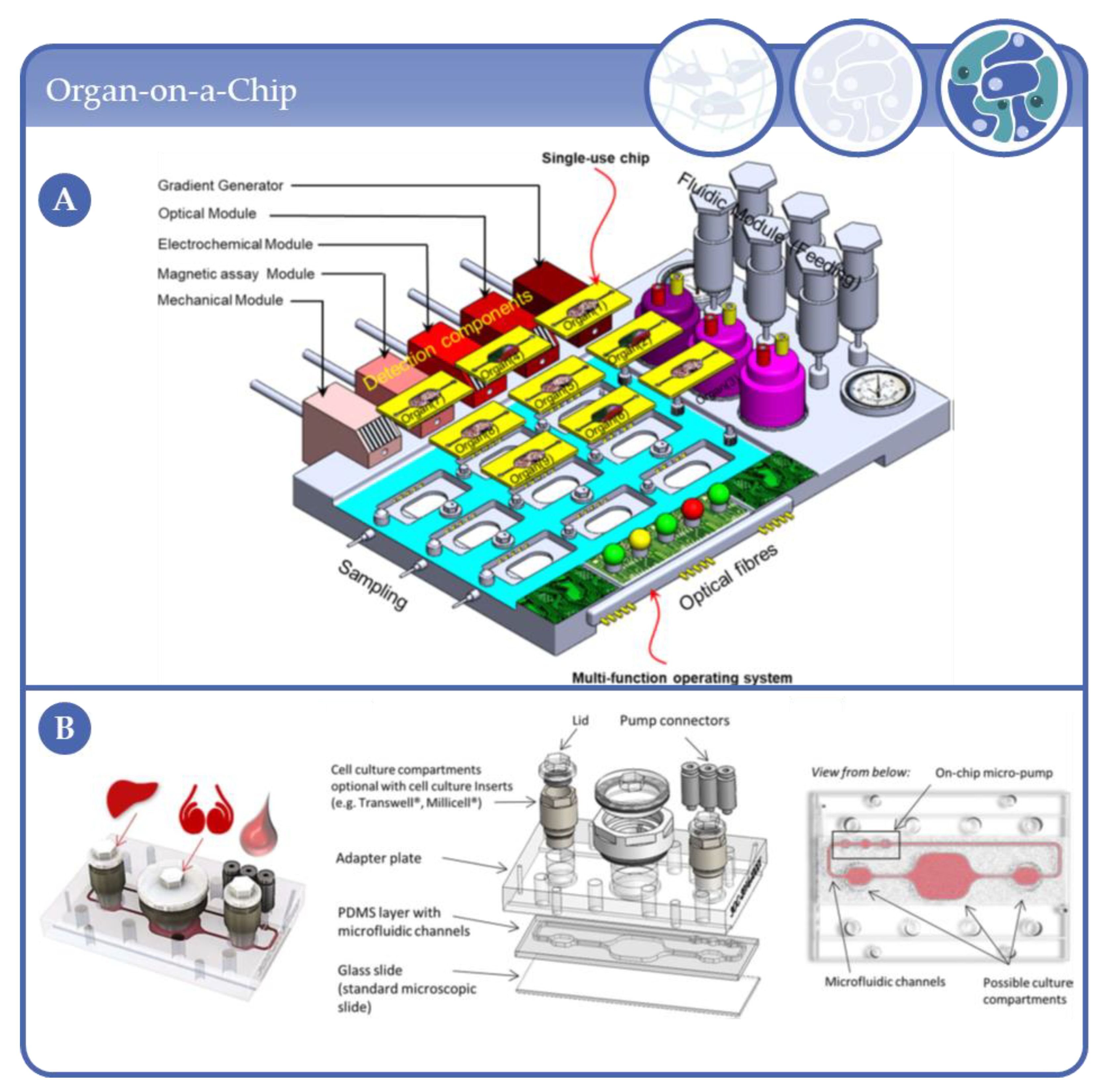
4.7. From Microfluidic Bioreactors of Complexity Level 3 to Organ-on-Chip Systems

In conclusion, it can be stated that as in the other complexity levels, most models from level 3 are used for in vitro-models. Three systems are suitable for HTS by simplifying the analysis by integrating, e.g., HPLC [192] or by reducing existing systems to microtiter plate format [176,195]. Complex 3D cell culture models with multiple cell types are getting closer and closer to physiological conditions which recommends their use in TE or clinical applications. For instance, MBRs which enable engineering of cardiac tissues [199,200] or small vessels [202,210]. By using hard scaffolds, the reconstruction of bone tissue is also possible [211]. Biphasic scaffolds also allow grafts that contain both bone and cartilage tissue [204].
Although TE is constantly developing, it is still a major step towards clinical application. With the exception of a tissue engineered kidney that was transplanted into rats [209], none of the models described here has found application in living organisms. A multi-component hollow fiber bioreactor by Jörg Gerlach is already being used in the clinic as an extracorporeal liver support [212]. However, it is so large that it does not qualify as an MBR for the scope of this review.
Even though multicellular aggregates have been proven valuable as cell-based in vitro-tool for many years, the number of studies using aggregates of different cell types, termed in the present review complexity level 3, constantly increase in the period examined. With the help of MBRs, a wide range of applications in the field of 3D cell culture can be covered. Simple models with only one cell type are possible as well as complex systems with heterotypic models, including those based on various stem cell technologies. In addition to more complex biological models, major improvements have been made, especially with regard to HTS and integrated analytical methods. By miniaturizing these components, micro-physiological systems (MPS) can be integrated with their peripherals, such as pumps, in small chips, the so-called organ-on-a-chip (OoC) systems (Figure 24). Various definitions of OoCs are in use, for example from the Wyss Institute of Harvard University or the European Organ-on-chip Society. In summary, OoCs are defined as micro-engineered devices with microfluidic channels with at least one cell culture compartment in which functional units of organs are modelled [213,214,215]. OoC systems do not only mimic human organ’s in vivo-physiology, for instance by providing an active flow, they also integrate actuators or sensors for further analysis.
By using our search terms, one publication was found that meets the requirements for OoCs and was therefore not qualified as an MBR. Zhang et al. used a hybrid strategy to apply 3D bioprinting in order to construct microfibrous scaffolding for engineering of endothelialized myocardium in a microfluidic chip [218]. As OoC models are not the aim of this review, we have not discussed this publication in detail. OoCs have been widely discussed in the literature, so the interested reader is referred to some excellent reviews in this field [219,220,221,222,223,224,225,226]. The idea of OoC was born about 10 years ago and is constantly evolving [227]. One trend here is to move towards body- or human-on-a-chip models by using multi-organ chips [217,228,229]. The topic of personalized medicine as well as disease models on chips, so-called micro-pathophysiological systems (MPPS), also has an important influence on the development of OoC [148,230,231,232]. Integrated OoCs offer several advantages regarding multiplexing, scaling, vascularization, and innervation [220,233,234] (Figure 24). The miniaturization of the systems is one possibility towards HTS. In combination with integrated sensors and analysis methods, a large amount of data can be generated. Machine learning or even artificial intelligence can be used to evaluate this data [235]. Especially in the field of drug development, in addition to the conventional in vitro-models, in silico-models are also used to predict side effects [236].
With the help of the results of in silico-models and the combination of complex biological models as established in various MBRs, integrated fluidics and sensors as well as smart algorithms and automated systems, the basis for highly complex systems for, e.g., drug development can be provided.

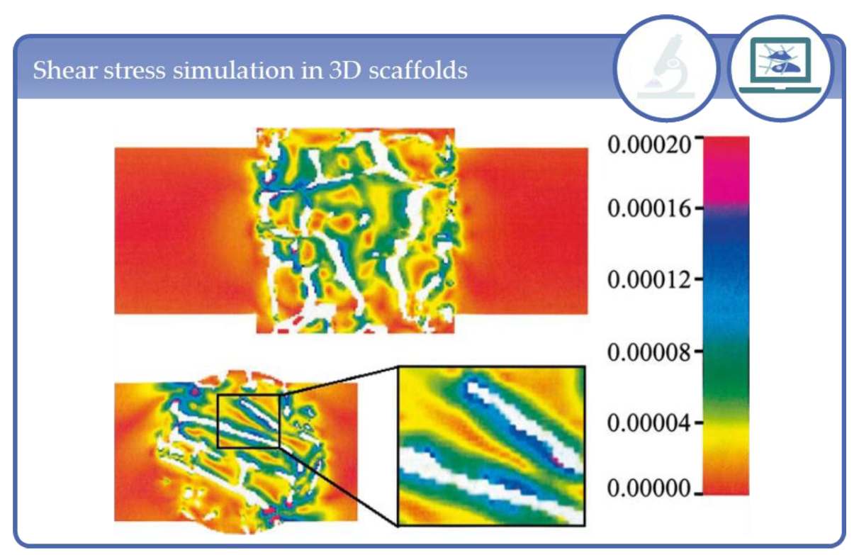
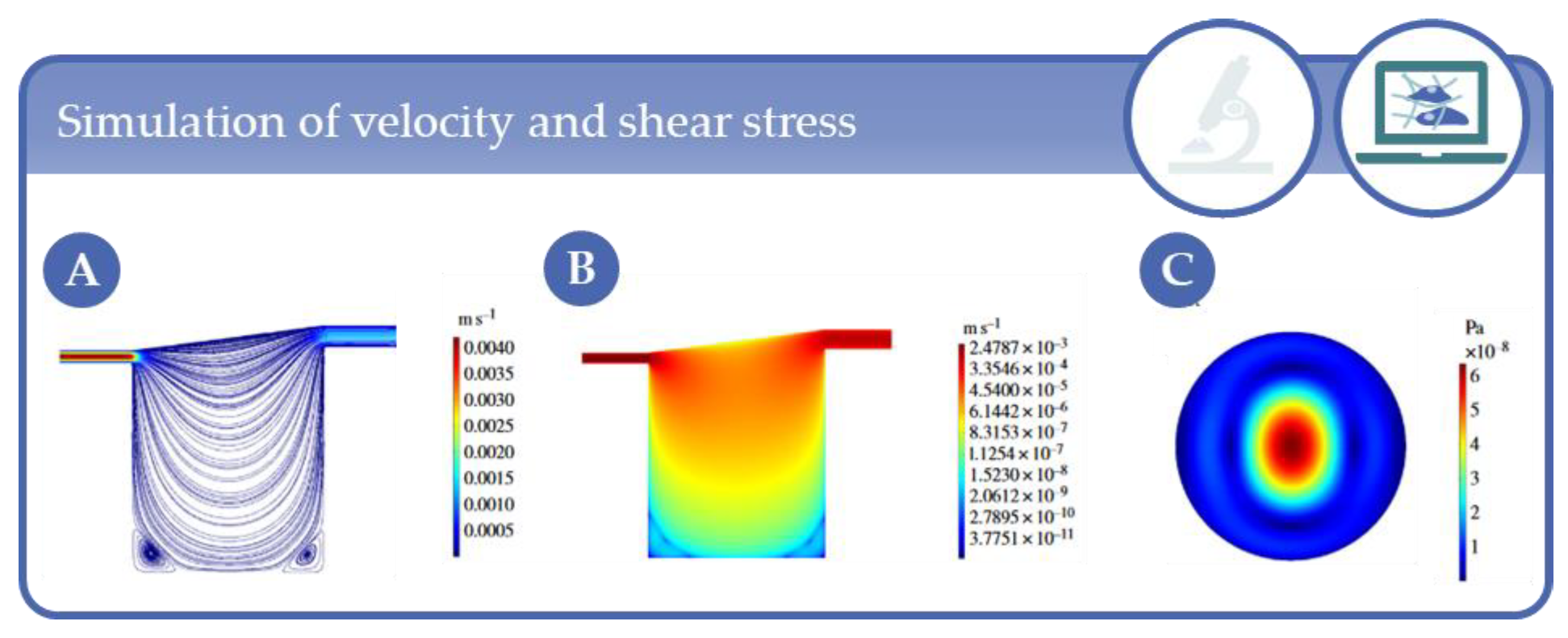
5. Simulation Studies

For a better overview of the reviewed systems, the figures in this section have been provided with icons (Figure 25), which identify those simulations that have been performed in addition to in vitro-experiments and pure in silico approaches. As described in the sections above, 3D cultivation of cells in MBRs plays an important role for biological and physiological in vitro-studies. However, the development of such systems is often associated with an elaborate optimization process. Mathematical models and computational fluid dynamics (CFD) simulations based on experimental in vitro-data can be a useful tool to optimize the bioreactor design as they enable the simulation of different culture conditions and their effect on cell behavior.
To investigate the optimal geometry and best media supply of multicellular aggregates, in their simulations Barisam et al. [128,129] compared toroidal and spheroidal aggregates of fibroblasts as well as microwell structures and U-shaped barriers (Figure 26). The results showed that the levels of oxygen and glucose as well as the shear stress are higher in the system with the U-shaped barriers than in the microwells. Furthermore, they showed that increasing spheroid diameter leads to a decreasing glucose and oxygen concentration inside the spheroid which increases the risk of quiescence and necrosis.
Several groups dedicated their simulations to engineering cartilage tissue. Williams et al. [237] used CFD simulations to quantify different parameters in order to improve the design and the experimental operating conditions of a concentric cylinder bioreactor used for cartilage TE. Their work focused on flow field, shear stress and media oxygen profiles around non-porous constructs. Sucosky et al. [238] wanted to improve cartilage production in spinner flasks. They determined the velocity and shear-rate fields of tissue constructs near the stirrer bar because due to the movement of the stirrer a turbulent and non-linear flow is generated in this area. To investigate this issue, they used particle-image velocity (PIV) models as well as two commercially available software tools to simulate the flow (FLUENT) and the geometry of the bioreactor (GAMBIT). Yu et al. [239] also used the FLUENT software to simulate medium flow and oxygen in a stirred MBR. The MBR consisted of a culture well with 22 mm diameter, 12 mm height and a medium volume of 4 mL. The results are comparable to typical values for cell cultures in a stirred MBR so that they could provide guidance for their operating parameters.
Simulations are also frequently used to better predict the experimental parameters in perfusion MBRs. Tajsoleiman et al. [240] focused on nutrient supply, metabolite removal and fluid shear stress in a 3D cartilage cell culture. Therefore, they used mathematical modelling and CFD simulations to study the effects of the perfusion flow rate, glucose concentration and pH to improve the geometrical scaffold design. Macrofuogo et al. [241] investigated the relationship between biochemical stimuli and cell response by analyzing the effect of insulin on glucose metabolism as a function of pore size distribution within a 3D scaffold with heterogeneous porosity. In this study, a mathematical model of 3D cell growth in a perfusion bioreactor was integrated into a model of insulin signaling pathways. Thus, the influence of insulin on cell metabolism and the effects of operative variables, such as the mean flow rate, could be simulated. The development of such a model which includes both mass transport and intracellular signaling pathways was described here for the first time. Porter et al. [242] simulated media flow and shear stress through 3D scaffolds which were reconstructed by microcomputer tomography (µCT) based on the Lattice–Boltzmann (LB)-method (Figure 27).
The application of the LB-method can be useful to determine appropriate shear stresses for different cell-biomaterial interactions and cell morphology in perfusion systems for 3D tissue constructs. The investigation of optimal shear stress ranges for 3D constructs produced by the means of µCT images is also the topic of the work of Raimondi et al. [243]. Their CFD simulations are a first attempt for a quantitative correlation of the applied hydrodynamic shear level and the resulting biosynthetic response of 3D engineered chondrocytes on PU foams in a perfusion bioreactor. Hyndman et al. [244] applied mathematical models of flow and mass transport to characterize concentration profiles of different flow rates, solutes and cell types in the commercially available bioreactor chamber Kirkstall QV900 [244] (Figure 28). However, they also pointed out the limitations of mathematical and computer-based models and the challenges involved in establishing these methods. In their opinion, the physical parameters used are often not precisely known. Therefore, modelling and experimentation should be applied in mutual complementarity.
This concept has already been implemented in several research groups in recent years by simulating only a limited number of parameters leading to optimized systems without the need for time-consuming or costly experiments. Because the work of the groups mentioned here has already been covered in detail in the respective sections above, only the partial simulations are listed in this section. For instance, Botchwey et al. [66] was able to determine parameters that prevent the particles from colliding with the bioreactor wall by calculating the motion of a microcarrier in a rotating bioreactor. Moraes and colleagues [35] showed another interesting result using a first-order linear finite element simulation. They used the ANSYS software to investigate the influence of relative differences in mechanical stiffness between cells and their surrounding hydrogel matrix. The results of the simulation suggest that the ratio between Young’s modulus of the cell and that of hydrogel has a strong impact on cellular deformation in a compressed matrix. However, the simulation of the flow profile as well as the shear stress was of major importance in most of the work [25,27,36,37,88,92,116,118,140,147,150,154,186,187,198,208,218,245,246,247]. Furthermore, the oxygen distribution [17,147,150,198,218] and mass transport of metabolites [17,28,36,37,105,246,247] within the respective bioreactor system were simulated as well as the distribution of a static magnetic [123] or electric field [193]. The software most often used to calculate the simulations was COMSOL Multiphysics. Further suitable software used by the different research groups to simulate flow velocities, oxygen profiles and shear stress were FLUENT, ADINA, ANSYS, Star-CCM+ and FEMLAB.
As discussed above, data from simulations and mathematical models in the field of MBRs are primarily used to adapt and optimize the systems with respect to, e.g., oxygen supply or flow rates. The next step is the development of so-called in silico-models. With the help of these models, biological processes are simulated by computers in order to obtain results comparable to in vitro-experiments. In the field of cartilage TE, for example, scaffold structures were optimized using finite element analysis (FEA) and cell differentiation was calculated with in silico-models to determine optimal parameters for chondrogenic or osteogenic differentiation [248]. In silico-models are also used in cancer research or toxicology [235,249,250]. However, to address the challenges, the parallel use of in silico- and in vitro-models is advantageous for the development of physiological models [232].

6. Conclusions

In this second part of our systematic review on the research area of 3D cell culture in MBRs we give a detailed description of the work published between 2000 and 2020 (9 July 2020) with focus on the 3D cell culture techniques, defined as complexity levels, the MBR types and their application fields, as well as on simulation studies. With this approach we show that with the help of MBRs a wide range of applications in the field of 3D cell culture can be covered.
If we take a look at the studies using immobilized cells in (hydro)gels, here defined as complexity level 1, it becomes apparent that during the first decade of the 21st century one initial focus in MBR applications was the generation of optimized tissue engineered in vitro-constructs for clinical applications. The emerging knowledge gained from this work on the impact of the microenvironment on cell functions further promoted the establishment of 3D in vitro-models for basic and preclinical research. In this course, the concept of HTS, i.e., miniaturization and parallelization, was incorporated into the design of MBRs to enable cell-based assays in the context of biomaterial and drug development under more physiological in vitro-conditions. Today, MBR systems for TE are manifold and primarily address the application of mechanical forces on the cultures to improve the functions of tissue engineered constructs, whereas work in the field of gel-based HTS focuses on the technical improvement, user friendliness and cost reduction of the systems to broaden the user community as much as currently present for 2D monolayer cultures.
With respect to approaches using multicellular aggregates with one cell type, classified as complexity level 2, our literature analysis revealed that this cell culture technique is by far the most common and versatile one in the research field under study. This is particularly reflected in the high number of publications in this group, namely 123 publications of 192 publications in total. The reason for this may be that multicellular aggregate cultures were established over 70 years ago and have been used since then in wide range of research fields, such as developmental and tumor biology, cytotoxicity testing and drug development. Hence, their application in MBRs is at present correspondingly multifaceted and affects mainly the fields of high(er) throughput 3D culture platforms for drug development and evaluation, for standardizations of, e.g., infection models, drug metabolization and large experimental approaches with regard to cell mass. However, the prominent applications in complexity level 2 are liver and bone models. Moreover, this type of culture can fairly be modeled which is why simulations studies are increasingly employed to optimize MBR setups with regard to, e.g., scaffold structure, shear stress, fluid flow and oxygenation with a strong tendency to develop in silico-approaches. Such in silico models may prospectively help to simulate biological processes by computers in order to obtain results comparable to in vitro-experiments. Finally, a trend towards a humanization can be observed, meaning that human cell sources are used more frequently.
Compared to complexity level 1 and 2, the relative number of publications in complexity level 3 has increased in the recent years: in the period of 2014 to 2019 almost by a factor of ten than compared to the period of 2000 to 2004 (see also review part I in this issue). Here, comparably with complexity level 1, a trend towards HTS can be recognized which is accompanied by the development of platforms with integrated sensors. In parallel, systems are being miniaturized which seamlessly leads over to OoC system technology. In addition to “healthy” tissue, disease models are increasingly being established which comprise tumor models, as well as models for the study of viral infections such as SARS-CoV which might also help to fight the SARS-CoV2 pandemic.

Author Contributions

Conceptualization, E.G., C.G. and B.A.; methodology, E.G., C.G. and B.A.; investigation, E.G., C.G., B.A. and C.N.; data curation, C.G.; writing—original draft preparation, E.G., C.G., B.A. and C.N.; writing—review and editing, E.G., C.G., B.A. and C.N.; visualization, E.G., C.G., B.A. and C.N. All authors have read and agreed to the published version of the manuscript.

Funding

This research received no external funding.

Institutional Review Board Statement

Not applicable.

Informed Consent Statement

Not applicable.

Acknowledgments

We would like to thank all the colleagues that provided full texts for this Review and at the same time apologize towards those colleagues that could not be mentioned in the manuscript.

Conflicts of Interest

The authors declare no conflict of interest.

References

  1. Vacanti, J.P.; Langer, R. Tissue engineering: The design and fabrication of living replacement devices for surgical reconstruction and transplantation. Lancet 1999, 354, S32–S34. [Google Scholar] [CrossRef]
  2. Vunjak-Novakovic, G.; Freed, L.E.; Biron, R.J.; Langer, R. Effects of mixing on the composition and morphology of tissue-engineered cartilage. AIChE J. 1996, 42, 850–860. [Google Scholar] [CrossRef]
  3. Carrier, R.L.; Papadaki, M.; Rupnick, M.; Schoen, F.J.; Bursac, N.; Langer, R.; Freed, L.E.; Vunjak-Novakovic, G. Cardiac tissue engineering: Cell seeding, cultivation parameters, and tissue construct char-acterization. Biotechnol. Bioeng. 1999, 64, 580–589. [Google Scholar] [CrossRef]
  4. Niklason, L.E.; Langer, R.S. Advances in tissue engineering of blood vessels and other tissues. Transpl. Immunol. 1997, 5, 303–306. [Google Scholar] [CrossRef]
  5. Niklason, L.E.; Gao, J.; Abbott, W.M.; Hirschi, K.K.; Houser, S.; Marini, R.; Langer, R. Functional Arteries Grown in Vitro. Science 1999, 284, 489–493. [Google Scholar] [CrossRef] [Green Version]
  6. Altman, G.H.; Horan, R.L.; Martin, I.; Farhadi, J.; Stark, P.R.H.; Volloch, V.; Richmond, J.C.; Vunjak-Novakovic, G.; Kaplan, D.L. Cell differentiation by mechanical stress. FASEB J. 2001, 16, 1–13. [Google Scholar] [CrossRef] [Green Version]
  7. Powell, C.A.; Smiley, B.L.; Mills, J.; VanDenburgh, H.H. Mechanical stimulation improves tissue-engineered human skeletal muscle. Am. J. Physiol. Physiol. 2002, 283, C1557–C1565. [Google Scholar] [CrossRef]
  8. Hahn, M.S.; McHale, M.K.; Wang, E.; Schmedlen, R.H.; West, J.L. Physiologic Pulsatile Flow Bioreactor Conditioning of Poly(ethylene glycol)-based Tissue Engineered Vascular Grafts. Ann. Biomed. Eng. 2006, 35, 190–200. [Google Scholar] [CrossRef]
  9. Wilkes, R.P.; McNulty, A.K.; Feeley, T.D.; Schmidt, M.A.; Kieswetter, K. Bioreactor for Application of Subatmospheric Pressure to Three-Dimensional Cell Culture. Tissue Eng. 2007, 13, 3003–3010. [Google Scholar] [CrossRef]
  10. Moretti, M.; Freed, L.E.; Padera, R.; Laganà, K.; Boschetti, F.; Raimondi, M.T. An integrated experimental–computational approach for the study of engineered cartilage constructs subjected to combined regimens of hydrostatic pressure and interstitial perfusion. Biomed Mater. Eng. 2008, 18, 273–278. [Google Scholar] [CrossRef]
  11. Lee, P.-Y.; Liu, Y.-C.; Wang, M.-X.; Hu, J.-J. Fibroblast-seeded collagen gels in response to dynamic equibiaxial mechanical stimuli: A biomechanical study. J. Biomech. 2018, 78, 134–142. [Google Scholar] [CrossRef] [PubMed]
  12. Langer, R.; Vacanti, J.P. Tissue engineering. Science 1993, 260, 920–926. [Google Scholar] [CrossRef] [PubMed] [Green Version]
  13. Langer, R.S.; Vacanti, J.P. Tissue Engineering: The Challenges Ahead. Sci. Am. 1999, 280, 86–89. [Google Scholar] [CrossRef] [PubMed]
  14. Lichtenberg, A.; Dumlu, G.; Walles, H.; Maringka, M.; Ringes-Lichtenberg, S.; Ruhparwar, A.; Mertsching, H.; Haverich, A. A multifunctional bioreactor for three-dimensional cell (co)-culture. Biomaterials 2005, 26, 555–562. [Google Scholar] [CrossRef] [PubMed]
  15. Hwang, Y.-S.; Cho, J.; Tay, F.; Heng, J.Y.Y.; Ho, R.; Kazarian, S.G.; Williams, D.R.; Boccaccini, A.R.; Polak, J.M.; Mantalaris, A. The use of murine embryonic stem cells, alginate encapsulation, and rotary microgravity bioreactor in bone tissue engineering. Biomaterials 2009, 30, 499–507. [Google Scholar] [CrossRef] [PubMed]
  16. Briegleb, W. The clinostat-a tool for analyzing the influence of acceleration on solid-liquid systems. In Proceedings of Workshop on space biology, Cologne, Germany, 9–11 March 1983; ESA-SP-206; European Space Agency: Paris, France, 1983. [Google Scholar]
  17. Wu, M.H.; Urban, J.P.G.; Cui, Z.; Cui, Z. Development of PDMS microbioreactor with well-defined and homogenous culture environment for chondrocyte 3-D culture. Biomed. Microdevices 2006, 8, 331–340. [Google Scholar] [CrossRef] [PubMed]
  18. Cui, Z.; Xu, X.; Trainor, N.; Triffitt, J.; Urban, J.; Tirlapur, U. Application of multiple parallel perfused microbioreactors and three-dimensional stem cell culture for toxicity testing. Toxicol. Vitr. 2007, 21, 1318–1324. [Google Scholar] [CrossRef] [PubMed]
  19. Wu, M.-H.; Huang, S.-B.; Cui, Z.; Cui, Z.; Sinha, A. A high throughput perfusion-based microbioreactor platform integrated with pneumatic micropumps for three-dimensional cell culture. Biomed. Microdevices 2007, 10, 309–319. [Google Scholar] [CrossRef]
  20. Ling, Y.; Rubin, J.; Deng, Y.; Huang, C.; Demirci, U.; Karp, J.M.; Khademhosseini, A. A cell-laden microfluidic hydrogel. Lab Chip 2007, 7, 756–762. [Google Scholar] [CrossRef]
  21. Chang, R.; Nam, J.; Holtorf, H.; Emami, K.; Jeevarajan, A.; Wu, H.; Sun, W. Direct cell writing of 3D tissue micro-organs for drug metabolism study. J. Biotechnol. 2008, 136, S144–S145. [Google Scholar] [CrossRef]
  22. Schätti, O.; Grad, S.; Goldhahn, J.; Salzmann, G.; Li, Z.; Alini, M.; Stoddart, M.J. A combination of shear and dynamic compression leads to mechanically induced chondrogenesis of human mesenchymal stem cells. Eur. Cells Mater. 2011, 22, 214–225. [Google Scholar] [CrossRef] [PubMed]
  23. Wimmer, M.A.; Grad, S.; Kaup, T.; Hänni, M.; Schneider, E.; Gogolewski, S.; Alini, M. Tribology Approach to the Engineering and Study of Articular Cartilage. Tissue Eng. 2004, 10, 1436–1445. [Google Scholar] [CrossRef] [PubMed]
  24. Cochis, A.; Grad, S.; Stoddart, M.J.; Farè, S.; Altomare, L.; Azzimonti, B.; Alini, M.; Rimondini, L. Bioreactor mechanically guided 3D mesenchymal stem cell chondrogenesis using a biocompatible novel thermo-reversible methylcellulose-based hydrogel. Sci. Rep. 2017, 7, srep45018. [Google Scholar] [CrossRef] [PubMed] [Green Version]
  25. Gharravi, A.M.; Orazizadeh, M.; Ansari-Asl, K.; Banoni, S.; Izadi, S.; Hashemitabar, M. Design and Fabrication of Anatomical Bioreactor Systems Containing Alginate Scaffolds for Cartilage Tissue Engineering. Avicenna J. Med Biotechnol. 2012, 4, 65–74. [Google Scholar]
  26. Correia, C.; Pereira, A.L.; Duarte, A.R.; Frias, A.M.; Pedro, A.J.; Oliveira, J.T.; Sousa, R.A.; Reis, R.L. Dynamic Culturing of Cartilage Tissue: The Significance of Hydrostatic Pressure. Tissue Eng. Part A 2012, 18, 1979–1991. [Google Scholar] [CrossRef] [Green Version]
  27. Santoro, R.; Olivares, A.L.; Brans, G.; Wirz, D.; Longinotti, C.; Lacroix, D.; Martin, I.; Wendt, D. Bioreactor based engineering of large-scale human cartilage grafts for joint resurfacing. Biomaterials 2010, 31, 8946–8952. [Google Scholar] [CrossRef] [Green Version]
  28. Jaeger, A.A.; Das, C.K.; Morgan, N.Y.; Pursley, R.H.; McQueen, P.G.; Hall, M.D.; Pohida, T.J.; Gottesman, M.M. Microfabricated polymeric vessel mimetics for 3-D cancer cell culture. Biomaterials 2013, 34, 8301–8313. [Google Scholar] [CrossRef] [Green Version]
  29. Sriram, R.; Van Criekinge, M.; Hansen, A.F.; Wang, Z.J.; Vigneron, D.B.; Wilson, D.M.; Keshari, K.R.; Kurhanewicz, J. Real-time measurement of hyperpolarized lactate production and efflux as a biomarker of tumor aggressiveness in an MR compatible 3D cell culture bioreactor. NMR Biomed. 2015, 28, 1141–1149. [Google Scholar] [CrossRef]
  30. Wu, M.-H.; Kuo, C.-Y. Application of high throughput perfusion micro 3-D cell culture platform for the precise study of cellular responses to extracellular conditions -effect of serum concentrations on the physiology of articular chondrocytes. Biomed. Microdevices 2010, 13, 131–141. [Google Scholar] [CrossRef]
  31. Huang, S.-B.; Wu, M.-H.; Wang, S.-S.; Sinha, A. Microfluidic cell culture chip with multiplexed medium delivery and efficient cell/scaffold loading mechanisms for high-throughput perfusion 3-dimensional cell culture-based assays. Biomed. Microdevices 2011, 13, 415–430. [Google Scholar] [CrossRef]
  32. Huang, S.-B.; Wang, S.-S.; Hsieh, C.-H.; Lin, Y.C.; Lai, C.-S.; Wu, M.-H. An integrated microfluidic cell culture system for high-throughput perfusion three-dimensional cell culture-based assays: Effect of cell culture model on the results of chemosensitivity assays. Lab Chip 2012, 13, 1133–1143. [Google Scholar] [CrossRef] [PubMed]
  33. Li, Z.; Kreiner, M.; Edrada-Ebel, R.; Cui, Z.; Van Der Walle, C.F.; Mardon, H.J. Perfusion culture enhanced human endometrial stromal cell growth in alginate-multivalent integrin α5β1 ligand scaffolds. J. Biomed. Mater. Res. Part A 2011, 99, 211–220. [Google Scholar] [CrossRef] [PubMed]
  34. Hsieh, C.-H.; Chen, Y.-D.; Huang, S.-F.; Wang, H.-M.; Wu, M.-H. The Effect of Primary Cancer Cell Culture Models on the Results of Drug Chemosensitivity Assays: The Application of Perfusion Microbioreactor System as Cell Culture Vessel. BioMed Res. Int. 2015, 2015, 1–10. [Google Scholar] [CrossRef] [PubMed]
  35. Moraes, C.; Wang, G.; Sun, Y.; A Simmons, C. A microfabricated platform for high-throughput unconfined compression of micropatterned biomaterial arrays. Biomaterials 2010, 31, 577–584. [Google Scholar] [CrossRef] [PubMed]
  36. Pagano, G.; Ventre, M.; Iannone, M.; Greco, F.; Maffettone, P.L.; Netti, P.A. Optimizing design and fabrication of microfluidic devices for cell cultures: An effective approach to control cell microenvironment in three dimensions. Biomicrofluidics 2014, 8, 046503. [Google Scholar] [CrossRef] [Green Version]
  37. Goldman, S.M.; Barabino, G.A. Cultivation of agarose-based microfluidic hydrogel promotes the development of large, full-thickness, tissue-engineered articular cartilage constructs. J. Tissue Eng. Regen. Med. 2014, 11, 572–581. [Google Scholar] [CrossRef]
  38. Vecchiatini, R.; Penolazzi, L.; Lambertini, E.; Angelozzi, M.; Morganti, C.; Mazzitelli, S.; Trombelli, L.; Nastruzzi, C.; Piva, R. Effect of dynamic three-dimensional culture on osteogenic potential of human periodontal ligament-derived mesenchymal stem cells entrapped in alginate microbeads. J. Periodontal Res. 2014, 50, 544–553. [Google Scholar] [CrossRef]
  39. Rödling, L.; Volz, E.M.; Raic, A.; Brändle, K.; Franzreb, M.; Lee-Thedieck, C. Magnetic Macroporous Hydrogels as a Novel Approach for Perfused Stem Cell Culture in 3D Scaffolds via Contactless Motion Control. Adv. Heal. Mater. 2018, 7, e1701403. [Google Scholar] [CrossRef]
  40. Holtfreter, J. A study of the mechanics of gastrulation. J. Exp. Zool. 1944, 95, 171–212. [Google Scholar] [CrossRef]
  41. Inch, W.R.; A McCredie, J.; Sutherland, R.M. Growth of nodular carcinomas in rodents compared with multi-cell spheroids in tissue culture. Growth 1970, 34, 271–282. [Google Scholar]
  42. Sutherland, R.M.; A McCredie, J.; Inch, W.R. Growth of multicell spheroids in tissue culture as a model of nodular carcinomas. J. Natl. Cancer Inst. 1971, 46, 113–120. [Google Scholar] [PubMed]
  43. Schwarz, R.P.; Wolf, D.A. Rotating bio-reactor cell culture apparatus. U.S. Patent No 4,988,623, 1991. [Google Scholar]
  44. Schwarz, R.P.; Wolf, D.A.; Trinh, T.T. Horizontally rotated cell culture system with a coaxial tubular oxygenator. U.S. Patent No 5,026,650, 1991. [Google Scholar]
  45. Gerecht-Nir, S.; Cohen, S.; Itskovitz-Eldor, J. Bioreactor cultivation enhances the efficiency of human embryoid body (hEB) formation and differentiation. Biotechnol. Bioeng. 2004, 86, 493–502. [Google Scholar] [CrossRef] [PubMed]
  46. Aucamp, J.; Calitz, C.; Bronkhorst, A.J.; Wrzesinski, K.; Hamman, S.; Gouws, C.; Pretorius, P.J. Cell-free DNA in a three-dimensional spheroid cell culture model: A preliminary study. Int. J. Biochem. Cell Biol. 2017, 89, 182–192. [Google Scholar] [CrossRef] [PubMed]
  47. Bramley, J.C.; Drummond, C.G.; Lennemann, N.J.; Good, C.A.; Kim, K.S.; Coyne, C.B. A Three-Dimensional Cell Culture System To Model RNA Virus Infections at the Blood-Brain Barrier. mSphere 2017, 2, e00206-17. [Google Scholar] [CrossRef] [Green Version]
  48. Drummond, C.G.; Nickerson, C.A.; Coyne, C.B. A Three-Dimensional Cell Culture Model To Study Enterovirus Infection of Polarized Intestinal Epithelial Cells. mSphere 2015, 1. [Google Scholar] [CrossRef] [Green Version]
  49. Sainz, B.; TenCate, V.; Uprichard, S.L. Three-dimensional Huh7 cell culture system for the study of Hepatitis C virus infection. Virol. J. 2009, 6, 103. [Google Scholar] [CrossRef] [Green Version]
  50. Papafragkou, E.; Hewitt, J.; Park, G.W.; Greening, G.; Vinjé, J. Challenges of Culturing Human Norovirus in Three-Dimensional Organoid Intestinal Cell Culture Models. PLoS ONE 2013, 8, e63485. [Google Scholar] [CrossRef]
  51. Carterson, A.J.; Zu Bentrup, K.H.; Ott, C.M.; Clarke, M.S.; Pierson, D.L.; Vanderburg, C.R.; Buchanan, K.L.; Nickerson, C.A.; Schurr, M.J. A549 Lung Epithelial Cells Grown as Three-Dimensional Aggregates: Alternative Tissue Culture Model for Pseudomonas aeruginosa Pathogenesis. Infect. Immun. 2005, 73, 1129–1140. [Google Scholar] [CrossRef] [Green Version]
  52. Crabbé, A.; Liu, Y.; Matthijs, N.; Rigole, P.; De La Fuente-Nùñez, C.; Davis, R.; Ledesma, M.A.; Sarker, S.; Van Houdt, R.; Hancock, R.E.W.; et al. Antimicrobial efficacy against Pseudomonas aeruginosa biofilm formation in a three-dimensional lung epithelial model and the influence of fetal bovine serum. Sci. Rep. 2017, 7, srep43321. [Google Scholar] [CrossRef] [PubMed] [Green Version]
  53. Nickerson, C.A.; Goodwin, T.J.; Terlonge, J.; Ott, C.M.; Buchanan, K.L.; Uicker, W.C.; Emami, K.; Leblanc, C.L.; Ramamurthy, R.; Clarke, M.S.; et al. Three-Dimensional Tissue Assemblies: Novel Models for the Study of Salmonella enterica Serovar Typhimurium Pathogenesis. Infect. Immun. 2001, 69, 7106–7120. [Google Scholar] [CrossRef] [PubMed] [Green Version]
  54. Zu Bentrup, K.H.; Ramamurthy, R.; Ott, C.M.; Emami, K.; Nelman-Gonzalez, M.; Wilson, J.W.; Richter, E.G.; Goodwin, T.J.; Alexander, J.S.; Pierson, D.L.; et al. Three-dimensional organotypic models of human colonic epithelium to study the early stages of enteric salmonellosis. Microbes Infect. 2006, 8, 1813–1825. [Google Scholar] [CrossRef] [PubMed]
  55. Radtke, A.L.; Wilson, J.W.; Sarker, S.; Nickerson, C.A. Analysis of Interactions of Salmonella Type Three Secretion Mutants with 3-D Intestinal Epithelial Cells. PLoS ONE 2010, 5, e15750. [Google Scholar] [CrossRef] [PubMed] [Green Version]
  56. De Weirdt, R.; Crabbé, A.; Roos, S.; Vollenweider, S.; Lacroix, C.; Van Pijkeren, J.P.; Britton, R.A.; Sarker, S.; Van De Wiele, T.; Nickerson, C.A. Glycerol Supplementation Enhances L. reuteri’s Protective Effect against S. Typhimurium Colonization in a 3-D Model of Colonic Epithelium. PLoS ONE 2012, 7, e37116. [Google Scholar] [CrossRef] [PubMed] [Green Version]
  57. Smith, Y.C.; Grande, K.K.; Rasmussen, S.B.; O’Brien, A.D. Novel Three-Dimensional Organoid Model for Evaluation of the Interaction of Uropathogenic Escherichia coli with Terminally Differentiated Human Urothelial Cells. Infect. Immun. 2006, 74, 750–757. [Google Scholar] [CrossRef] [Green Version]
  58. Carvalho, H.M.; Teel, L.D.; Goping, G.; O’Brien, A.D. A three-dimensional tissue culture model for the study of attach and efface lesion formation by enteropathogenic and enterohaemorrhagic Escherichia coli. Cell. Microbiol. 2005, 7, 1771–1781. [Google Scholar] [CrossRef]
  59. Warren, C.A.; Destura, R.V.; Sevilleja, J.E.A.D.; Barroso, L.F.; Carvalho, H.; Barrett, L.J.; O’Brien, A.D.; Guerrant, R.L. Detection of Epithelial-Cell Injury, and Quantification of Infection, in the HCT-8 Organoid Model of Cryptosporidiosis. J. Infect. Dis. 2008, 198, 143–149. [Google Scholar] [CrossRef]
  60. Łaniewski, P.; Gomez, A.; Hire, G.; So, M.; Herbst-Kralovetz, M.M. Human Three-Dimensional Endometrial Epithelial Cell Model To Study Host Interactions with Vaginal Bacteria and Neisseria gonorrhoeae. Infect. Immun. 2017, 85, e01049-16. [Google Scholar] [CrossRef] [Green Version]
  61. David, J.; Sayer, N.M.; Sarkar-Tyson, M. The use of a three-dimensional cell culture model to investigate host–pathogen interactions of Francisella tularensis in human lung epithelial cells. Microbes Infect. 2014, 16, 735–745. [Google Scholar] [CrossRef]
  62. Chang, T.T.; Hughes-Fulford, M. Molecular mechanisms underlying the enhanced functions of three-dimensional hepatocyte aggregates. Biomaterials 2014, 35, 2162–2171. [Google Scholar] [CrossRef] [PubMed] [Green Version]
  63. Detamore, M.S.; Athanasiou, K.A. Use of a Rotating Bioreactor toward Tissue Engineering the Temporomandibular Joint Disc. Tissue Eng. 2005, 11, 1188–1197. [Google Scholar] [CrossRef] [PubMed] [Green Version]
  64. Papadaki, M.; Bursac, N.; Langer, R.; Merok, J.; Vunjak-Novakovic, G.; Freed, L.E. Tissue engineering of functional cardiac muscle: Molecular, structural, and electrophysiological studies. Am. J. Physiol. Circ. Physiol. 2001, 280, H168–H178. [Google Scholar] [CrossRef] [PubMed]
  65. Rungarunlert, S.; Klincumhom, N.; Bock, I.; Nemes, C.; Techakumphu, M.; Pirity, M.K.; Dinnyes, A. Enhanced cardiac differentiation of mouse embryonic stem cells by use of the slow-turning, lateral vessel (STLV) bioreactor. Biotechnol. Lett. 2011, 33, 1565–1573. [Google Scholar] [CrossRef] [Green Version]
  66. Botchwey, E.A.; Pollack, S.R.; Levine, E.M.; Laurencin, C.T. Bone tissue engineering in a rotating bioreactor using a microcarrier matrix system. J. Biomed. Mater. Res. 2001, 55, 242–253. [Google Scholar] [CrossRef]
  67. Goldstein, A.S. Effect of convection on osteoblastic cell growth and function in biodegradable polymer foam scaffolds. Biomaterials 2001, 22, 1279–1288. [Google Scholar] [CrossRef]
  68. Marlovits, S.; Tichy, B.; Truppe, M.; Gruber, D.; Vécsei, V. Chondrogenesis of Aged Human Articular Cartilage in a Scaffold-Free Bioreactor. Tissue Eng. 2003, 9, 1215–1226. [Google Scholar] [CrossRef]
  69. Montani, C.; Steimberg, N.; Boniotti, J.; Biasiotto, G.; Zanella, I.; Diafera, G.; Biunno, I.; Caimi, L.; Mazzoleni, G.; Di Lorenzo, D. Fibroblasts maintained in 3 dimensions show a better differentiation state and higher sensitivity to estrogens. Toxicol. Appl. Pharmacol. 2014, 280, 421–433. [Google Scholar] [CrossRef]
  70. Samuelson, L.; Gerber, D.A. Improved Function and Growth of Pancreatic Cells in a Three-Dimensional Bioreactor Environment. Tissue Eng. Part C Methods 2013, 19, 39–47. [Google Scholar] [CrossRef]
  71. Valmikinathan, C.M.; Hoffman, J.; Yu, X. Impact of scaffold micro and macro architecture on Schwann cell proliferation under dynamic conditions in a rotating wall vessel bioreactor. Mater. Sci. Eng. C 2011, 31, 22–29. [Google Scholar] [CrossRef] [Green Version]
  72. Hjelm, B.E.; Berta, A.N.; Nickerson, C.A.; Arntzen, C.J.; Herbst-Kralovetz, M.M. Development and Characterization of a Three-Dimensional Organotypic Human Vaginal Epithelial Cell Model1. Biol. Reprod. 2010, 82, 617–627. [Google Scholar] [CrossRef] [PubMed] [Green Version]
  73. Lamarca, H.; Ott, C.; Zu Bentrup, K.H.; Leblanc, C.; Pierson, D.; Nelson, A.; Scandurro, A.; Whitley, G.S.; Nickerson, C.; Morris, C. Three-dimensional growth of extravillous cytotrophoblasts promotes differentiation and invasion. Placenta 2005, 26, 709–720. [Google Scholar] [CrossRef] [PubMed]
  74. Skardal, A.; Sarker, S.F.; Crabbé, A.; Nickerson, C.A.; Prestwich, G.D. The generation of 3-D tissue models based on hyaluronan hydrogel-coated microcarriers within a rotating wall vessel bioreactor. Biomaterials 2010, 31, 8426–8435. [Google Scholar] [CrossRef] [PubMed]
  75. Smit, T.; Calitz, C.; Willers, C.; Svitina, H.; Hamman, J.; Fey, S.J.; Gouws, C.; Wrzesinski, K. Characterization of an Alginate Encapsulated LS180 Spheroid Model for Anti-colorectal Cancer Compound Screening. ACS Med. Chem. Lett. 2020, 11, 1014–1021. [Google Scholar] [CrossRef] [PubMed]
  76. Wrzesinski, K.; Fey, S.J. Metabolic Reprogramming and the Recovery of Physiological Functionality in 3D Cultures in Micro-Bioreactors. Bioengineering 2018, 5, 22. [Google Scholar] [CrossRef] [Green Version]
  77. Yamashita, T.; Takayama, K.; Sakurai, F.; Mizuguchi, H. Billion-scale production of hepatocyte-like cells from human induced pluripotent stem cells. Biochem. Biophys. Res. Commun. 2018, 496, 1269–1275. [Google Scholar] [CrossRef]
  78. Cortiella, J.; Niles, J.; Cantu, A.; Brettler, A.; Pham, A.; Vargas, G.; Winston, S.; Wang, J.; Walls, S.; Nichols, J.E. Influence of Acellular Natural Lung Matrix on Murine Embryonic Stem Cell Differentiation and Tissue Formation. Tissue Eng. Part A 2010, 16, 2565–2580. [Google Scholar] [CrossRef] [Green Version]
  79. Lei, X.-H.; Ning, L.-N.; Cao, Y.-J.; Liu, S.; Zhang, S.-B.; Qiu, Z.-F.; Hu, H.-M.; Zhang, H.-S.; Liu, S.; Duan, E. NASA-Approved Rotary Bioreactor Enhances Proliferation of Human Epidermal Stem Cells and Supports Formation of 3D Epidermis-Like Structure. PLoS ONE 2011, 6, e26603. [Google Scholar] [CrossRef]
  80. Li, W.-J.; Tuan, R.S. Fabrication and Application of Nanofibrous Scaffolds in Tissue Engineering. Curr. Protoc. Cell Biol. 2009, 42, 25.2.1–25.2.12. [Google Scholar] [CrossRef]
  81. Quail, D.F.; Maciel, T.J.; Rogers, K.; Postovit, L.-M. A Unique 3D In Vitro Cellular Invasion Assay. J. Biomol. Screen. 2012, 17, 1088–1095. [Google Scholar] [CrossRef] [Green Version]
  82. Giselbrecht, S.; Truckenmüller, R. Formkörper, Verfahren zu seiner Herstellung und Verwendung. DE Patent WO2006/007948 A1, 30 June 2005. [Google Scholar]
  83. Gottwald, E.; Giselbrecht, S.; Augspurger, C.; Lahni, B.; Dambrowsky, N.; Truckenmüller, R.; Piotter, V.; Gietzelt, T.; Wendt, O.; Pfleging, W.; et al. A chip-based platform for the in vitro generation of tissues in three-dimensional organization. Lab Chip 2007, 7, 777–785. [Google Scholar] [CrossRef] [PubMed]
  84. Gottwald, E.; Kleintschek, T.; Giselbrecht, S.; Truckenmüller, R.; Altmann, B.; Worgull, M.; Döpfert, J.; Schad, L.; Heilmann, M. Characterization of a chip-based bioreactor for three-dimensional cell cultivation via Magnetic Resonance Imaging. Zeitschrift Medizinische Physik 2013, 23, 102–110. [Google Scholar] [CrossRef] [PubMed]
  85. Hoesl, M.A.U.; Kleimaier, D.; Hu, R.; Malzacher, M.; Nies, C.; Gottwald, E.; Schad, L.R. 23Na Triple-quantum signal of in vitro human liver cells, liposomes, and nanoparticles: Cell viability assessment vs. separation of intra- and extracellular signal. J. Magn. Reson. Imaging 2019, 50, 435–444. [Google Scholar] [CrossRef] [PubMed]
  86. Kleimaier, D.; Goerke, S.; Nies, C.; Zaiss, M.; Kunz, P.; Bachert, P.; Ladd, M.E.; Gottwald, E.; Schad, L.R. The cellular heat shock response monitored by chemical exchange saturation transfer MRI. Sci. Rep. 2020, 10, 1–12. [Google Scholar] [CrossRef]
  87. Neubauer, A.; Nies, C.; Schepkin, V.D.; Hu, R.; Malzacher, M.; Chacón-Caldera, J.; Thiele, D.; Gottwald, E.; Schad, L.R. Tracking protein function with sodium multi quantum spectroscopy in a 3D-tissue culture based on microcavity arrays. Sci. Rep. 2017, 7, 3943. [Google Scholar] [CrossRef] [Green Version]
  88. Powers, M.J.; Domansky, K.; Kaazempur-Mofrad, M.R.; Kalezi, A.; Capitano, A.; Upadhyaya, A.; Kurzawski, P.; Wack, K.E.; Stolz, D.B.; Kamm, R.; et al. A microfabricated array bioreactor for perfused 3D liver culture. Biotechnol. Bioeng. 2002, 78, 257–269. [Google Scholar] [CrossRef]
  89. Sivaraman, A.; Leach, J.K.; Townsend, S.; Iida, T.; Hogan, B.J.; Stolz, D.B.; Fry, R.; Samson, L.D.; Tannenbaum, S.R.; Griffith, L.G. A Microscale In Vitro Physiological Model of the Liver: Predictive Screens for Drug Metabolism and Enzyme Induction. Curr. Drug Metab. 2005, 6, 569–591. [Google Scholar] [CrossRef]
  90. Powers, M.J.; Janigian, D.M.; Wack, K.E.; Baker, C.S.; Stolz, D.B.; Griffith, L.G. Functional Behavior of Primary Rat Liver Cells in a Three-Dimensional Perfused Microarray Bioreactor. Tissue Eng. 2002, 8, 499–513. [Google Scholar] [CrossRef]
  91. Yates, C.; Shepard, C.R.; Papworth, G.; Dash, A.; Stolz, D.B.; Tannenbaum, S.; Griffith, L.; Wells, A. Novel Three-Dimensional Organotypic Liver Bioreactor to Directly Visualize Early Events in Metastatic Progression. Adv. Cancer Res. 2007, 97, 225–246. [Google Scholar] [CrossRef]
  92. Weise, F.; Fernekorn, U.; Hampl, J.; Klett, M.; Schober, A. Analysis and comparison of oxygen consumption of HepG2 cells in a monolayer and three-dimensional high density cell culture by use of a matrigrid®. Biotechnol. Bioeng. 2013, 110, 2504–2512. [Google Scholar] [CrossRef]
  93. Giselbrecht, S.; Gietzelt, T.; Gottwald, E.; Trautmann, C.; Truckenmüller, R.; Weibezahn, K.F.; Welle, A. 3D tissue culture substrates produced by microthermoforming of pre-processed polymer films. Biomed. Microdevices 2006, 8, 191–199. [Google Scholar] [CrossRef] [PubMed]
  94. Bingel, C.; Koeneke, E.; Ridinger, J.; Bittmann, A.; Sill, M.; Peterziel, H.; Wrobel, J.K.; Rettig, I.; Milde, T.; Fernekorn, U.; et al. Three-dimensional tumor cell growth stimulates autophagic flux and recapitulates chemotherapy resistance. Cell Death Dis. 2017, 8, e3013. [Google Scholar] [CrossRef] [PubMed] [Green Version]
  95. Knazek, R.A.; Gullino, P.M.; Kohler, P.O.; Dedrick, R.L. Cell Culture on Artificial Capillaries: An Approach to Tissue Growth in vitro. Science 1972, 178, 65–67. [Google Scholar] [CrossRef] [PubMed]
  96. Nyberg, S.L.; Shatford, R.A.; Cerra, F.B.; Hu, W.-S. Bilirubin Conjugation in a Three Compartment Hollow Fiber Bioreactor. In Proceedings of the Twelfth Annual International Conference of the IEEE Engineering in Medicine and Biology Society, Philadelphia, PA, USA, 1–4 November 1990; Institute of Electrical and Electronics Engineers (IEEE): New York, NY, USA, 2005; pp. 443–444. [Google Scholar]
  97. Pless, G.; Steffen, I.; Zeilinger, K.; Sauer, I.M.; Katenz, E.; Kehr, D.C.; Roth, S.; Mieder, T.; Schwartlander, R.; Müller, C.; et al. Evaluation of Primary Human Liver Cells in Bioreactor Cultures for Extracorporeal Liver Support on the Basis of Urea Production. Artif. Organs 2006, 30, 686–694. [Google Scholar] [CrossRef]
  98. Gerlach, J.C.; Encke, J.; Hole, O.; Müller, C.; Courtney, J.M.; Neuhaus, P. Hepatocyte culture between three dimensionally arranged biomatrix-coated independent artifi-cial capillary systems and sinusoidal endothelial cell co-culture compartments. Int. J. Artif. Organs. 1994, 17, 301–306. [Google Scholar] [CrossRef]
  99. Gerlach, J.; Schnoy, N.; Smith, M.D.; Neuhaus, P. Hepatocyte Culture between Woven Capillary Networks: A Microscopy Study. Artif. Organs 1994, 18, 226–230. [Google Scholar] [CrossRef]
  100. Ring, A.; Gerlach, J.; Peters, G.; Pazin, B.J.; Minervini, C.F.; Turner, M.E.; Thompson, R.L.; Triolo, F.; Gridelli, B.; Miki, T. Hepatic Maturation of Human Fetal Hepatocytes in Four-Compartment Three-Dimensional Perfusion Culture. Tissue Eng. Part C Methods 2010, 16, 835–845. [Google Scholar] [CrossRef]
  101. Zeilinger, K.; Schreiter, T.; Darnell, M.; Söderdahl, T.; Lübberstedt, M.; Dillner, B.; Knobeloch, D.; Nüssler, A.K.; Gerlach, J.C.; Andersson, T.B. Scaling Down of a Clinical Three-Dimensional Perfusion Multicompartment Hollow Fiber Liver Bioreactor Developed for Extracorporeal Liver Support to an Analytical Scale Device Useful for Hepatic Pharmacological In Vitro Studies. Tissue Eng. Part C Methods 2011, 17, 549–556. [Google Scholar] [CrossRef]
  102. Ulvestad, M.; Darnell, M.; Molden, E.; Ellis, E.; Åsberg, A.; Andersson, T.B. Evaluation of Organic Anion-Transporting Polypeptide 1B1 and CYP3A4 Activities in Primary Human Hepatocytes and HepaRG Cells Cultured in a Dynamic Three-Dimensional Bioreactor System. J. Pharmacol. Exp. Ther. 2012, 343, 145–156. [Google Scholar] [CrossRef] [Green Version]
  103. Gerlach, J.C.; Encke, J.; Hole, O.; Müller, C.; Ryan, C.J.; Neuhaus, P. Bioreactor for a larger scale hepatocyte in vitro perfusion. Transplantation 1994, 58, 984–988. [Google Scholar] [CrossRef] [PubMed]
  104. Lübberstedt, M.; Müller-Vieira, U.; Biemel, K.M.; Darnell, M.; A Hoffmann, S.; Knöspel, F.; Wönne, E.C.; Knobeloch, D.; Nussler, A.K.; Gerlach, J.C.; et al. Serum-free culture of primary human hepatocytes in a miniaturized hollow-fibre membrane bioreactor for pharmacologicalin vitrostudies. J. Tissue Eng. Regen. Med. 2012, 9, 1017–1026. [Google Scholar] [CrossRef] [PubMed]
  105. De Bartolo, L.; Salerno, S.; Curcio, E.; Piscioneri, A.; Rende, M.; Morelli, S.; Tasselli, F.; Bader, A.; Drioli, E. Human hepatocyte functions in a crossed hollow fiber membrane bioreactor. Biomaterials 2009, 30, 2531–2543. [Google Scholar] [CrossRef] [PubMed]
  106. Schmelzer, E.; Triolo, F.; Turner, M.E.; Thompson, R.L.; Zeilinger, K.; Reid, L.M.; Gridelli, B.; Gerlach, J.C. Three-Dimensional Perfusion Bioreactor Culture Supports Differentiation of Human Fetal Liver Cells. Tissue Eng. Part A 2010, 16, 2007–2016. [Google Scholar] [CrossRef]
  107. Darnell, M.; Ulvestad, M.; Ellis, E.; Weidolf, L.; Andersson, T.B. In Vitro Evaluation of Major In Vivo Drug Metabolic Pathways Using Primary Human Hepatocytes and HepaRG Cells in Suspension and a Dynamic Three-Dimensional Bioreactor System. J. Pharmacol. Exp. Ther. 2012, 343, 134–144. [Google Scholar] [CrossRef] [Green Version]
  108. Hoekstra, R.; Nibourg, G.A.A.; Van Der Hoeven, T.V.; Plomer, G.; Seppen, J.; Ackermans, M.T.; Camus, S.; Kulik, W.; Van Gulik, T.M.; Elferink, R.P.O.; et al. Phase 1 and Phase 2 Drug Metabolism and Bile Acid Production of HepaRG Cells in a Bioartificial Liver in Absence of Dimethyl Sulfoxide. Drug Metab. Dispos. 2013, 41, 562–567. [Google Scholar] [CrossRef] [Green Version]
  109. Flendrig, L.M.; Velde, A.A.T.; Chamuleau, R.A. Semipermeable Hollow Fiber Membranes in Hepatocyte Bioreactors: A Prerequisite for a Successful Bioartificial Liver? Artif. Organs 2008, 21, 1177–1181. [Google Scholar] [CrossRef]
  110. Tapia, F.; Vogel, T.; Genzel, Y.; Behrendt, I.; Hirschel, M.; Gangemi, J.D.; Reichl, U. Production of high-titer human influenza A virus with adherent and suspension MDCK cells cultured in a single-use hollow fiber bioreactor. Vaccine 2014, 32, 1003–1011. [Google Scholar] [CrossRef]
  111. Rodday, B.; Hirschhaeuser, F.; Walenta, S.; Mueller-Klieser, W. Semiautomatic Growth Analysis of Multicellular Tumor Spheroids. J. Biomol. Screen. 2011, 16, 1119–1124. [Google Scholar] [CrossRef] [Green Version]
  112. Tostões, R.M.; Leite, S.B.; Serra, M.; Jensen, J.; Björquist, P.; Carrondo, M.J.T.; Brito, C.; Alves, P.M. Human liver cell spheroids in extended perfusion bioreactor culture for repeated-dose drug testing. Hepatology 2012, 55, 1227–1236. [Google Scholar] [CrossRef]
  113. Egger, D.; Fischer, M.; Clementi, A.; Ribitsch, V.; Hansmann, J.; Kasper, C. Development and Characterization of a Parallelizable Perfusion Bioreactor for 3D Cell Culture. Bioengeering 2017, 4, 51. [Google Scholar] [CrossRef] [PubMed] [Green Version]
  114. Egger, D.; Spitz, S.; Fischer, M.; Handschuh, S.; Glosmann, M.; Friemert, B.; Egerbacher, M.; Kasper, C. Application of a Parallelizable Perfusion Bioreactor for Physiologic 3D Cell Culture. Cells Tissues Organs 2017, 203, 316–326. [Google Scholar] [CrossRef] [PubMed]
  115. Birru, B.; Mekala, N.K.; Rao, S. Improved osteogenic differentiation of umbilical cord blood MSCs using custom made perfusion bioreactor. Biomed. J. 2018, 41, 290–297. [Google Scholar] [CrossRef] [PubMed]
  116. Schmid, J.; Schwarz, S.; Meier-Staude, R.; Sudhop, S.; Clausen-Schaumann, H.; Schieker, M.; Huber, R. A Perfusion Bioreactor System for Cell Seeding and Oxygen-Controlled Cultivation of Three-Dimensional Cell Cultures. Tissue Eng. Part C Methods 2018, 24, 585–595. [Google Scholar] [CrossRef]
  117. Spitkovsky, D.; Lemke, K.; Förster, T.; Römer, R.; Wiedemeier, S.; Hescheler, J.; Sachinidis, A.; Gastrock, G. Generation of Cardiomyocytes in Pipe-Based Microbioreactor Under Segmented Flow. Cell. Physiol. Biochem. 2016, 38, 1883–1896. [Google Scholar] [CrossRef] [Green Version]
  118. Vetsch, J.R.; Betts, D.C.; Muller, R.; Hofmann, S. Flow velocity-driven differentiation of human mesenchymal stromal cells in silk fibroin scaffolds: A combined experimental and computational approach. PLoS ONE 2017, 12, e0180781. [Google Scholar] [CrossRef] [Green Version]
  119. Sart, S.; Tomasi, R.F.-X.; Amselem, G.; Baroud, C.N. Multiscale cytometry and regulation of 3D cell cultures on a chip. Nat. Commun. 2017, 8, 1–13. [Google Scholar] [CrossRef] [Green Version]
  120. Toh, Y.-C.; Zhang, C.; Zhang, J.; Khong, Y.M.; Chang, S.; Samper, V.D.; Van Noort, D.; Hutmacher, D.W.; Yu, H. A novel 3D mammalian cell perfusion-culture system in microfluidic channels. Lab Chip 2007, 7, 302–309. [Google Scholar] [CrossRef]
  121. Ong, S.-M.; Zhang, C.; Toh, Y.-C.; Kim, S.H.; Foo, H.L.; Tan, C.H.; Van Noort, D.; Park, S.; Yu, H. A gel-free 3D microfluidic cell culture system. Biomaterials 2008, 29, 3237–3244. [Google Scholar] [CrossRef]
  122. Zhang, C.; Chia, S.-M.; Ong, S.-M.; Zhang, S.; Toh, Y.-C.; Van Noort, D.; Yu, H. The controlled presentation of TGF-β1 to hepatocytes in a 3D-microfluidic cell culture system. Biomaterials 2009, 30, 3847–3853. [Google Scholar] [CrossRef]
  123. Izzo, L.; Tunesi, M.; Boeri, L.; Laganà, M.; Giordano, C.; Raimondi, M.T. Influence of the static magnetic field on cell response in a miniaturized optically accessible bioreactor for 3D cell culture. Biomed. Microdevices 2019, 21, 1–12. [Google Scholar] [CrossRef] [PubMed] [Green Version]
  124. Laganà, M.; Raimondi, M.T. A miniaturized, optically accessible bioreactor for systematic 3D tissue engineering research. Biomed. Microdevices 2011, 14, 225–234. [Google Scholar] [CrossRef] [PubMed]
  125. Tunesi, M.; Fusco, F.; Fiordaliso, F.; Corbelli, A.; Biella, G.; Raimondi, M.T. Optimization of a 3D Dynamic Culturing System for In Vitro Modeling of Frontotemporal Neurodegeneration-Relevant Pathologic Features. Front. Aging Neurosci. 2016, 8, 146. [Google Scholar] [CrossRef] [PubMed] [Green Version]
  126. Yu, F.; Deng, R.; Tong, W.H.; Huan, L.; Way, N.C.; IslamBadhan, A.; Iliescu, C.; Yu, H. A perfusion incubator liver chip for 3D cell culture with application on chronic hepatotoxicity testing. Sci. Rep. 2017, 7, 1–16. [Google Scholar] [CrossRef] [Green Version]
  127. Fu, C.-Y.; Tseng, S.-Y.; Yang, S.-M.; Hsu, L.; Liu, C.-H.; Chang, H.-Y. A microfluidic chip with a U-shaped microstructure array for multicellular spheroid formation, culturing and analysis. Biofabrication 2014, 6, 015009. [Google Scholar] [CrossRef] [Green Version]
  128. Barisam, M.; Saidi, M.S.; Kashaninejad, N.; Vadivelu, R.K.; Nguyen, A.V. Numerical Simulation of the Behavior of Toroidal and Spheroidal Multicellular Aggregates in Microfluidic Devices with Microwell and U-Shaped Barrier. Micromachines 2017, 8, 358. [Google Scholar] [CrossRef] [Green Version]
  129. Barisam, M.; Saidi, M.S.; Kashaninejad, N.; Nguyen, A.V. Prediction of Necrotic Core and Hypoxic Zone of Multicellular Spheroids in a Microbioreactor with a U-Shaped Barrier. Micromachines 2018, 9, 94. [Google Scholar] [CrossRef] [Green Version]
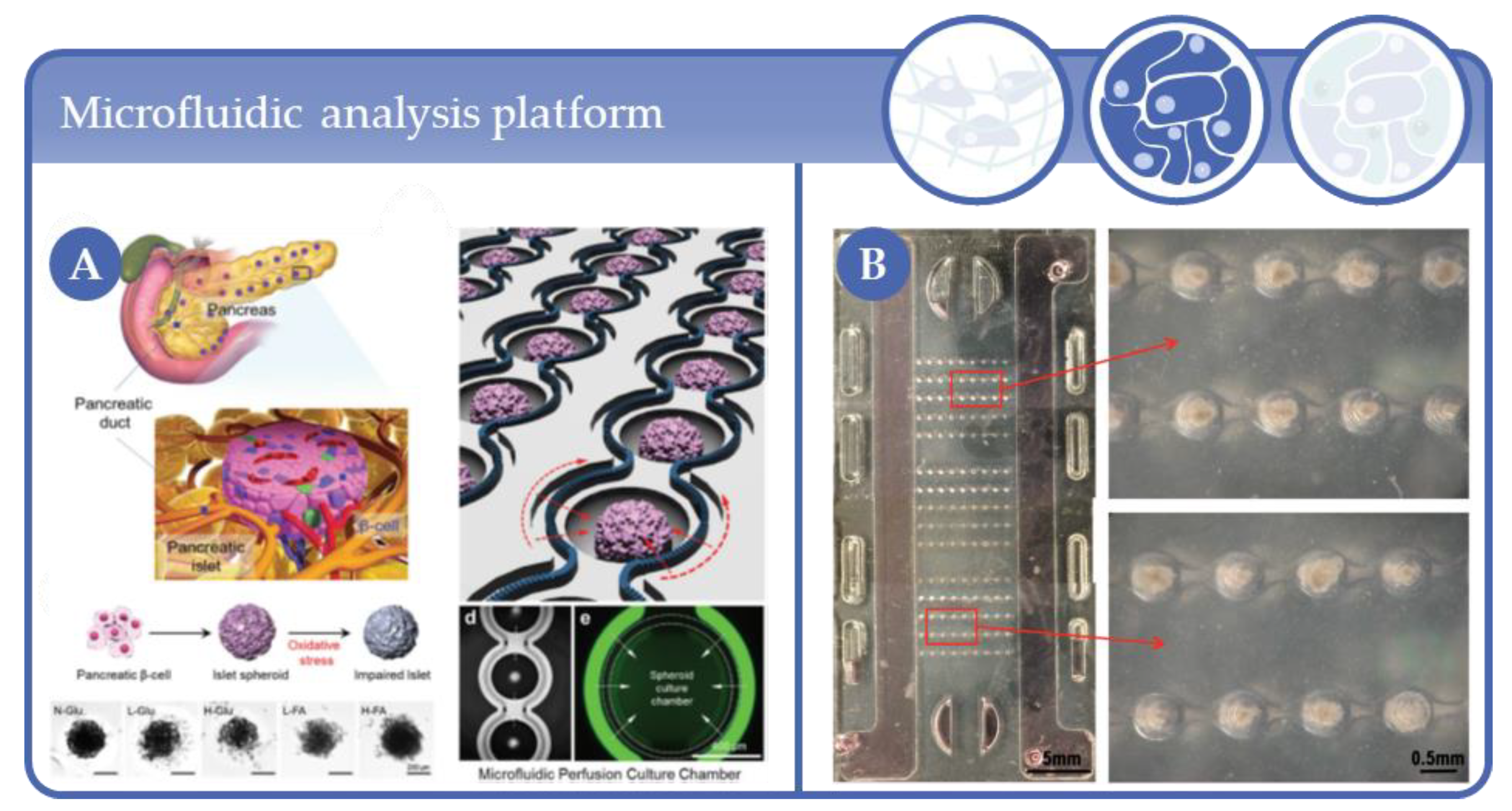
  130. Lee, S.H.; Hong, S.; Song, J.; Cho, B.; Han, E.J.; Kondapavulur, S.; Kim, D.; Lee, L.P. Microphysiological Analysis Platform of Pancreatic Islet β-Cell Spheroids. Adv. Heal. Mater. 2018, 7, 1701111. [Google Scholar] [CrossRef]
  131. Cimetta, E.; Sirabella, D.; Yeager, K.; Davidson, K.; Simon, J.; Moon, R.T.; Vunjak-Novakovic, G. Microfluidic bioreactor for dynamic regulation of early mesodermal commitment in human pluripotent stem cells. Lab Chip 2012, 13, 355–364. [Google Scholar] [CrossRef] [Green Version]
  132. Christoffersson, J.; Bergström, G.; Schwanke, K.; Kempf, H.; Zweigerdt, R.; Mandenius, C.-F. A Microfluidic Bioreactor for Toxicity Testing of Stem Cell Derived 3D Cardiac Bodies. Adv. Struct. Saf. Stud. 2016, 159–168. [Google Scholar] [CrossRef]
  133. Christoffersson, J.; Mandenius, C.-F. Using a Microfluidic Device for Culture and Drug Toxicity Testing of 3D Cells. Breast Cancer 2019, 1994, 235–241. [Google Scholar] [CrossRef]
  134. Wen, Y.; Zhang, X.; Yang, S.-T. Microplate-reader compatible perfusion microbioreactor array for modular tissue culture and cytotoxicity assays. Biotechnol. Prog. 2010, 26, 1135–1144. [Google Scholar] [CrossRef] [PubMed]
  135. Bancroft, G.N.; Sikavitsas, V.I.; Dolder, J.V.D.; Sheffield, T.L.; Ambrose, C.G.; Jansen, J.A.; Mikos, A.G. Fluid flow increases mineralized matrix deposition in 3D perfusion culture of marrow stromal osteoblasts in a dose-dependent manner. Proc. Natl. Acad. Sci. USA 2002, 99, 12600–12605. [Google Scholar] [CrossRef] [PubMed] [Green Version]
  136. Bancroft, G.N.; Sikavitsas, V.I.; Mikos, A.G. Technical Note: Design of a Flow Perfusion Bioreactor System for Bone Tissue-Engineering Applications. Tissue Eng. 2003, 9, 549–554. [Google Scholar] [CrossRef] [Green Version]
  137. Sikavitsas, V.I.; Bancroft, G.N.; Holtorf, H.L.; Jansen, J.A.; Mikos, A.G. Mineralized matrix deposition by marrow stromal osteoblasts in 3D perfusion culture increases with increasing fluid shear forces. Proc. Natl. Acad. Sci. USA 2003, 100, 14683–14688. [Google Scholar] [CrossRef] [Green Version]
  138. Frangos, J.A.; McIntire, L.V.; Eskin, S.G. Shear stress induced stimulation of mammalian cell metabolism. Biotechnol. Bioeng. 1988, 32, 1053–1060. [Google Scholar] [CrossRef] [Green Version]
  139. Gomes, M.E.; Sikavitsas, V.I.; Behravesh, E.; Reis, R.L.; Mikos, A.G. Effect of flow perfusion on the osteogenic differentiation of bone marrow stromal cells cultured on starch-based three-dimensional scaffolds. J. Biomed. Mater. Res. 2003, 67, 87–95. [Google Scholar] [CrossRef] [Green Version]
  140. Bartnikowski, M.; Klein, T.J.; Melchels, F.P.; Woodruff, M.A. Effects of scaffold architecture on mechanical characteristics and osteoblast response to static and perfusion bioreactor cultures. Biotechnol. Bioeng. 2014, 111, 1440–1451. [Google Scholar] [CrossRef]
  141. Leclerc, E.; Sakai, Y.; Fujii, T. Perfusion culture of fetal human hepatocytes in microfluidic environments. Biochem. Eng. J. 2004, 20, 143–148. [Google Scholar] [CrossRef]
  142. Baudoin, R.; Griscom, L.; Prot, J.M.; Legallais, C.; Leclerc, E. Behavior of HepG2/C3A cell cultures in a microfluidic bioreactor. Biochem. Eng. J. 2011, 53, 172–181. [Google Scholar] [CrossRef]
  143. Baudoin, R.; Alberto, G.; Legendre, A.; Paullier, P.; Naudot, M.; Fleury, M.-J.; Jacques, S.; Griscom, L.; Leclerc, E. Investigation of expression and activity levels of primary rat hepatocyte detoxication genes under various flow rates and cell densities in microfluidic biochips. Biotechnol. Prog. 2014, 30, 401–410. [Google Scholar] [CrossRef] [PubMed]
  144. Legendre, A.; Baudoin, R.; Alberto, G.; Paullier, P.; Naudot, M.; Bricks, T.; Brocheton, J.; Jacques, S.; Cotton, J.; Leclerc, E. Metabolic Characterization of Primary Rat Hepatocytes Cultivated in Parallel Microfluidic Biochips. J. Pharm. Sci. 2013, 102, 3264–3276. [Google Scholar] [CrossRef] [PubMed]
  145. Prot, J.M.; Aninat, C.; Griscom, L.; Razan, F.; Brochot, C.; Guillouzo, C.G.; Legallais, C.; Corlu, A.; Leclerc, E. Improvement of HepG2/C3a cell functions in a microfluidic biochip. Biotechnol. Bioeng. 2011, 108, 1704–1715. [Google Scholar] [CrossRef] [PubMed]
  146. Prot, J.-M.; Videau, O.; Brochot, C.; Legallais, C.; Bénech, H.; Leclerc, E. A cocktail of metabolic probes demonstrates the relevance of primary human hepatocyte cultures in a microfluidic biochip for pharmaceutical drug screening. Int. J. Pharm. 2011, 408, 67–75. [Google Scholar] [CrossRef]
  147. Tania, M.; Hsu, M.N.; Png, S.N.; Leo, H.L.; Toh, G.W.; Birgersson, E. Perfusion enhanced polydimethylsiloxane based scaffold cell culturing system for multi-well drug screening platform. Biotechnol. Prog. 2014, 30, 418–428. [Google Scholar] [CrossRef] [PubMed]
  148. Candini, O.; Grisendi, G.; Foppiani, E.M.; Brogli, M.; Aramini, B.; Masciale, V.; Spano, C.; Petrachi, T.; Veronesi, E.; Conte, P.; et al. A Novel 3D In Vitro Platform for Pre-Clinical Investigations in Drug Testing, Gene Therapy, and Immuno-oncology. Sci. Rep. 2019, 9, 1–12. [Google Scholar] [CrossRef] [PubMed] [Green Version]
  149. Fröhlich, M.; Grayson, W.L.; Marolt, D.; Gimble, J.M.; Kregar-Velikonja, N.; Vunjak-Novakovic, G. Bone Grafts Engineered from Human Adipose-Derived Stem Cells in Perfusion Bioreactor Culture. Tissue Eng. Part A 2010, 16, 179–189. [Google Scholar] [CrossRef]
  150. Grayson, W.L.; Marolt, D.; Bhumiratana, S.; Fröhlich, M.; Guo, X.E.; Vunjak-Novakovic, G. Optimizing the medium perfusion rate in bone tissue engineering bioreactors. Biotechnol. Bioeng. 2010, 108, 1159–1170. [Google Scholar] [CrossRef] [Green Version]
  151. Grayson, W.L.; Bhumiratana, S.; Cannizzaro, C.; Chao, P.-H.G.; Lennon, D.P.; Caplan, A.I.; Vunjak-Novakovic, G. Effects of Initial Seeding Density and Fluid Perfusion Rate on Formation of Tissue-Engineered Bone. Tissue Eng. Part A 2008, 14, 1809–1820. [Google Scholar] [CrossRef]
  152. Ostrovidov, S.; Jiang, J.; Sakai, Y.; Fujii, T. Membrane-Based PDMS Microbioreactor for Perfused 3D Primary Rat Hepatocyte Cultures. Biomed. Microdevices 2004, 6, 279–287. [Google Scholar] [CrossRef]
  153. Ostrovidov, S.; Sakai, Y.; Fujii, T. Integration of a pump and an electrical sensor into a membrane-based PDMS microbioreactor for cell culture and drug testing. Biomed. Microdevices 2011, 13, 847–864. [Google Scholar] [CrossRef] [PubMed]
  154. Costa, P.F.; Vaquette, C.; Baldwin, J.; Chhaya, M.; Gomes, M.E.; Reis, R.L.; Theodoropoulos, C.; Hutmacher, D.W. Biofabrication of customized bone grafts by combination of additive manufacturing and bioreactor knowhow. Biofabrication 2014, 6, 035006. [Google Scholar] [CrossRef] [PubMed] [Green Version]
  155. De Lora, J.A.; Velasquez, J.L.; Carroll, N.J.; Freyer, J.P.; Shreve, A.P. Centrifugal Generation of Droplet-Based 3D Cell Cultures. SLAS Technol. Transl. Life Sci. Innov. 2020, 25, 436–445. [Google Scholar] [CrossRef]
  156. Hongo, T.; Kajikawa, M.; Ishida, S.; Ozawa, S.; Ohno, Y.; Sawada, J.-I.; Umezawa, A.; Ishikawa, Y.; Kobayashi, T.; Honda, H. Three-dimensional high-density culture of HepG2 cells in a 5-ml radial-flow bioreactor for construction of artificial liver. J. Biosci. Bioeng. 2005, 99, 237–244. [Google Scholar] [CrossRef]
  157. Kensah, G.; Gruh, I.; Viering, J.; Schümann, H.; Dahlmann, J.; Meyer, H.; Skvorc, D.; Bär, A.; Akhyari, P.; Heisterkamp, A.; et al. A Novel Miniaturized Multimodal Bioreactor for Continuous In Situ Assessment of Bioartificial Cardiac Tissue During Stimulation and Maturation. Tissue Eng. Part C Methods 2011, 17, 463–473. [Google Scholar] [CrossRef] [Green Version]
  158. Scaglione, S.; Zerega, B.; Badano, R.; Benatti, U.; Fato, M.M.; Quarto, R. A three-dimensional traction/torsion bioreactor system for tissue engineering. Int. J. Artif. Organs 2010, 33, 362–369. [Google Scholar] [CrossRef]
  159. Zhang, Y.S.; Aleman, J.; Shin, S.R.; Kilic, T.; Kim, D.; Shaegh, S.A.M.; Massa, S.; Riahi, R.; Chae, S.; Hu, N.; et al. Multisensor-integrated organs-on-chips platform for automated and continual in situ monitoring of organoid behaviors. Proc. Natl. Acad. Sci. USA 2017, 114, E2293–E2302. [Google Scholar] [CrossRef] [Green Version]
  160. Kleinhans, C.; Mohan, R.R.; Vacun, G.; Schwarz, T.L.; Haller, B.; Sun, Y.; Kahlig, A.; Kluger, P.J.; Finne-Wistrand, A.; Walles, H.; et al. A perfusion bioreactor system efficiently generates cell-loaded bone substitute materials for addressing critical size bone defects. Biotechnol. J. 2015, 10, 1727–1738. [Google Scholar] [CrossRef] [Green Version]
  161. Linti, C.; Zipfel, A.; Schenk, M.; Dauner, M.; Doser, M.; Viebahn, R.; Becker, H.; Planck, H. Cultivation of Porcine Hepatocytes in Polyurethane Nonwovens as Part of a Biohybrid Liver Support System. Int. J. Artif. Organs 2002, 25, 994–1000. [Google Scholar] [CrossRef]
  162. Mauney, J.R.; Sjostorm, S.; Blumberg, J.; Horan, R.; O’Leary, J.P.; Vunjak-Novakovic, G.; Volloch, V.; Kaplan, D.L. Mechanical Stimulation Promotes Osteogenic Differentiation of Human Bone Marrow Stromal Cells on 3-D Partially Demineralized Bone Scaffolds In Vitro. Calcif. Tissue Int. 2004, 74, 458–468. [Google Scholar] [CrossRef]
  163. Driessen-Mol, A.A.; Driessen, N.J.B.; Rutten, M.C.M.; Hoerstrup, S.P.; Bouten, C.V.C.; Baaijens, F.P.T. Tissue Engineering of Human Heart Valve Leaflets: A Novel Bioreactor for a Strain-Based Conditioning Approach. Ann. Biomed. Eng. 2005, 33, 1778–1788. [Google Scholar] [CrossRef] [Green Version]
  164. A Thompson, C.; Colon-Hernandez, P.; Pomerantseva, I.; MacNeil, B.D.; Nasseri, B.; Vacanti, J.P.; Oesterle, S.N. A Novel Pulsatile, Laminar Flow Bioreactor for the Development of Tissue-Engineered Vascular Structures. Tissue Eng. 2002, 8, 1083–1088. [Google Scholar] [CrossRef] [PubMed]
  165. Weiss, S.; Henle, P.; Roth, W.; Bock, R.; Boeuf, S.; Richter, W. Design and characterization of a new bioreactor for continuous ultra-slow uniaxial distraction of a three-dimensional scaffold-free stem cell culture. Biotechnol. Prog. 2010, 27, 86–94. [Google Scholar] [CrossRef] [PubMed]
  166. Wendt, D.; Marsano, A.; Jakob, M.; Heberer, M.; Martin, I. Oscillating perfusion of cell suspensions through three-dimensional scaffolds enhances cell seeding efficiency and uniformity. Biotechnol. Bioeng. 2003, 84, 205–214. [Google Scholar] [CrossRef]
  167. Saini, S.; Wick, T.M. Concentric Cylinder Bioreactor for Production of Tissue Engineered Cartilage: Effect of Seeding Density and Hydrodynamic Loading on Construct Development. Biotechnol. Prog. 2003, 19, 510–521. [Google Scholar] [CrossRef]
  168. Wang, B.; Wang, G.; To, F.; Butler, J.R.; Claude, A.; McLaughlin, R.M.; Williams, L.N.; Curry, A.L.D.J.; Liao, J. Myocardial Scaffold-Based Cardiac Tissue Engineering: Application of Coordinated Mechanical and Electrical Stimulations. Langmuir 2013, 29, 11109–11117. [Google Scholar] [CrossRef]
  169. Santoro, M.; Lamhamedi-Cherradi, S.-E.; Menegaz, B.A.; Ludwig, J.A.; Mikos, A.G. Flow perfusion effects on three-dimensional culture and drug sensitivity of Ewing sarcoma. Proc. Natl. Acad. Sci. USA 2015, 112, 10304–10309. [Google Scholar] [CrossRef] [Green Version]
  170. Radisic, M.; Euloth, M.; Yang, L.; Langer, R.; Freed, L.E.; Vunjak-Novakovic, G. High-density seeding of myocyte cells for cardiac tissue engineering. Biotechnol. Bioeng. 2003, 82, 403–414. [Google Scholar] [CrossRef]
  171. Ramadhan, W.; Ohama, Y.; Minamihata, K.; Moriyama, K.; Wakabayashi, R.; Goto, M.; Kamiya, N. Redox-responsive functionalized hydrogel marble for the generation of cellular spheroids. J. Biosci. Bioeng. 2020, 130, 416–423. [Google Scholar] [CrossRef]
  172. Tostões, R.M.; Leite, S.B.; Miranda, J.P.; Sousa, M.; Wang, D.I.; Carrondo, M.J.; Alves, P.M. Perfusion of 3D encapsulated hepatocytes-A synergistic effect enhancing long-term functionality in bioreactors. Biotechnol. Bioeng. 2011, 108, 41–49. [Google Scholar] [CrossRef]
  173. Rebelo, S.P.; Costa, R.; Silva, M.M.; Marcelino, P.; Brito, C.; Alves, P.C.; Brito, C. Three-dimensional co-culture of human hepatocytes and mesenchymal stem cells: Improved functionality in long-term bioreactor cultures. J. Tissue Eng. Regen. Med. 2015, 11, 2034–2045. [Google Scholar] [CrossRef] [PubMed]
  174. Hwa, A.J.; Fry, R.C.; Sivaraman, A.; So, P.T.; Samson, L.D.; Stolz, D.B.; Griffith, L.G. Rat liver sinusoidal endothelial cells survive without exogenous VEGF in 3D perfused co-cultures with hepatocytes. FASEB J. 2007, 21, 2564–2579. [Google Scholar] [CrossRef] [PubMed] [Green Version]
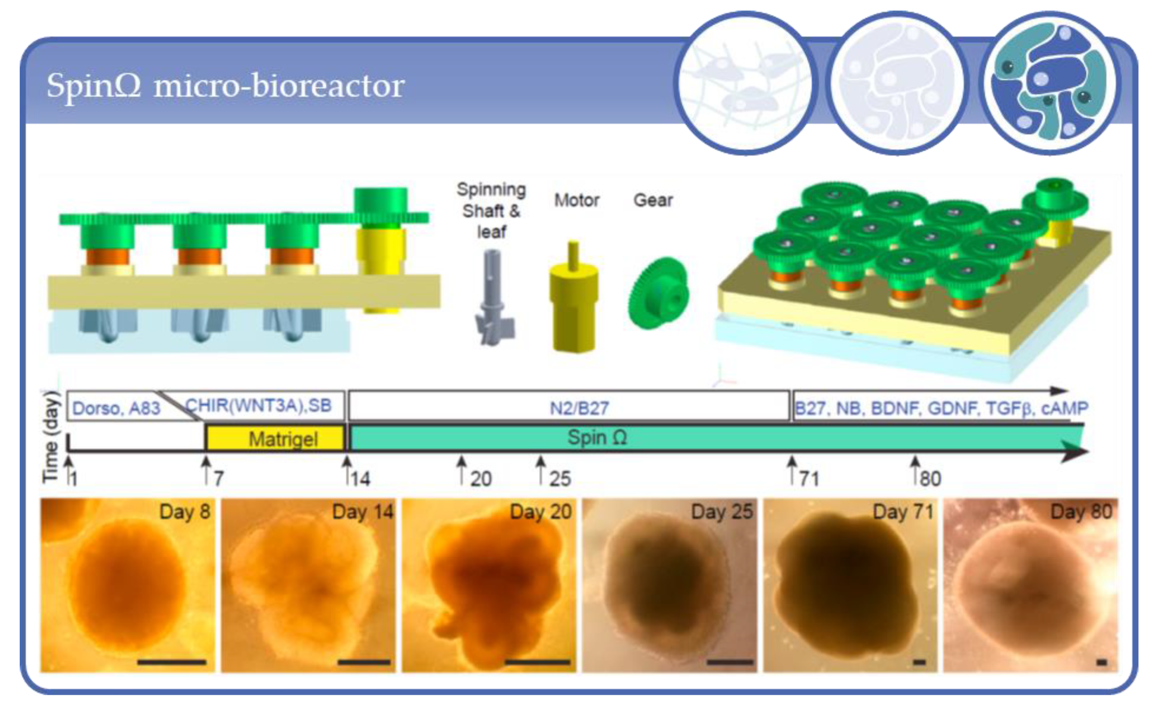
  175. Qian, X.; Jacob, F.; Song, M.M.; Nguyen, H.N.; Song, H.; Ming, G.-L. Generation of human brain region–specific organoids using a miniaturized spinning bioreactor. Nat. Protoc. 2018, 13, 565–580. [Google Scholar] [CrossRef] [PubMed]
  176. Qian, X.; Nguyen, H.N.; Song, M.M.; Hadiono, C.; Ogden, S.C.; Hammack, C.; Yao, B.; Hamersky, G.R.; Jacob, F.; Zhong, C.; et al. Brain-Region-Specific Organoids Using Mini-bioreactors for Modeling ZIKV Exposure. Cell 2016, 165, 1238–1254. [Google Scholar] [CrossRef] [PubMed] [Green Version]
  177. Lancaster, M.A.; Renner, M.; Martin, C.-A.; Wenzel, D.; Bicknell, L.S.; Hurles, M.E.; Homfray, T.; Penninger, J.M.; Jackson, A.P.; Knoblich, J.A. Cerebral organoids model human brain development and microcephaly. Nat. Cell Biol. 2013, 501, 373–379. [Google Scholar] [CrossRef] [PubMed]
  178. DiStefano, T.; Chen, H.Y.; Panebianco, C.; Kaya, K.D.; Brooks, M.J.; Gieser, L.; Morgan, N.Y.; Pohida, T.; Swaroop, A. Accelerated and Improved Differentiation of Retinal Organoids from Pluripotent Stem Cells in Rotating-Wall Vessel Bioreactors. Stem Cell Rep. 2018, 10, 300–313. [Google Scholar] [CrossRef] [Green Version]
  179. Salerno-Gonçalves, R.; Fasano, A.; Sztein, M.B. Development of a Multicellular Three-dimensional Organotypic Model of the Human Intestinal Mucosa Grown Under Microgravity. J. Vis. Exp. 2016, e54148. [Google Scholar] [CrossRef]
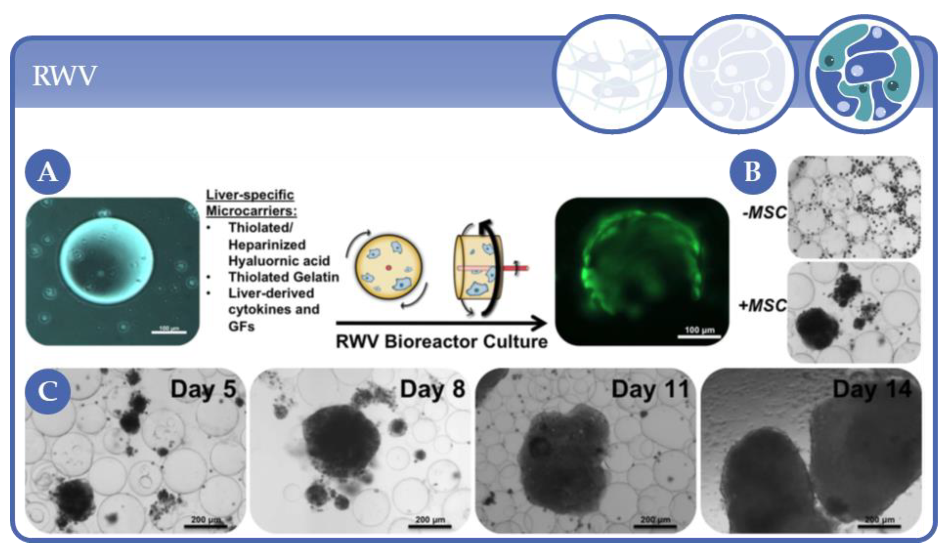
  180. Devarasetty, M.; Wang, E.; Soker, S.; Skardal, A. Mesenchymal stem cells support growth and organization of host-liver colorectal-tumor organoids and possibly resistance to chemotherapy. Biofabrication 2017, 9, 021002. [Google Scholar] [CrossRef]
  181. Skardal, A.; Devarasetty, M.; Rodman, C.; Atala, A.; Soker, S. Liver-Tumor Hybrid Organoids for Modeling Tumor Growth and Drug Response In Vitro. Ann. Biomed. Eng. 2015, 43, 2361–2373. [Google Scholar] [CrossRef] [Green Version]
  182. Barrila, J.; Yang, J.; Crabbé, A.; Sarker, S.F.; Liu, Y.; Ott, C.M.; Nelman-Gonzalez, M.A.; Clemett, S.J.; Nydam, S.D.; Forsyth, R.J.; et al. Three-dimensional organotypic co-culture model of intestinal epithelial cells and macrophages to study Salmonella enterica colonization patterns. NPJ Microgravity 2017, 3, 1–12. [Google Scholar] [CrossRef]
  183. Crabbé, A.; Sarker, S.F.; Van Houdt, R.; Ott, C.M.; Leys, N.; Cornelis, P.; Nickerson, C.A. Alveolar epithelium protects macrophages from quorum sensing-induced cytotoxicity in a three-dimensional co-culture model. Cell. Microbiol. 2010, 13, 469–481. [Google Scholar] [CrossRef] [PubMed]
  184. Goodwin, T.J.; McCarthy, M.; Cohrs, R.J.; Kaufer, B.B. 3D tissue-like assemblies: A novel approach to investigate virus–cell interactions. Methods 2015, 90, 76–84. [Google Scholar] [CrossRef] [PubMed]
  185. Wilkinson, D.C.; Mellody, M.; Meneses, L.K.; Hope, A.C.; Dunn, B.S.; Gomperts, B.N. Development of a Three-Dimensional Bioengineering Technology to Generate Lung Tissue for Personalized Disease Modeling. Curr. Protoc. Stem Cell Biol. 2018, 46, e56. [Google Scholar] [CrossRef] [PubMed] [Green Version]
  186. Schepers, A.; Li, C.; Chhabra, A.; Seney, B.T.; Bhatia, S.N. Engineering a perfusable 3D human liver platform from iPS cells. Lab Chip 2016, 16, 2644–2653. [Google Scholar] [CrossRef]
  187. Ghiaseddin, A.; Pouri, H.; Soleimani, M.; Vasheghani-Farahani, E.; Tafti, H.A.; Hashemi-Najafabadi, S. Cell laden hydrogel construct on-a-chip for mimicry of cardiac tissue in-vitro study. Biochem. Biophys. Res. Commun. 2017, 484, 225–230. [Google Scholar] [CrossRef]
  188. Goldman, S.M.; Barabino, G. Spatial Engineering of Osteochondral Tissue Constructs Through Microfluidically Directed Differentiation of Mesenchymal Stem Cells. BioResearch Open Access 2016, 5, 109–117. [Google Scholar] [CrossRef] [Green Version]
  189. Mauleon, G.; Fall, C.P.; Eddington, D.T. Precise Spatial and Temporal Control of Oxygen within In Vitro Brain Slices via Microfluidic Gas Channels. PLoS ONE 2012, 7, e43309. [Google Scholar] [CrossRef] [Green Version]
  190. Chung, S.; Sudo, R.; Mack, P.J.; Wan, C.-R.; Vickerman, V.; Kamm, R.D. Cell migration into scaffolds under co-culture conditions in a microfluidic platform. Lab Chip 2009, 9, 269–275. [Google Scholar] [CrossRef]
  191. Van Midwoud, P.M.; Groothuis, G.M.; Merema, M.T.; Verpoorte, E. Microfluidic biochip for the perifusion of precision-cut rat liver slices for metabolism and toxicology studies. Biotechnol. Bioeng. 2010, 105, 184–194. [Google Scholar] [CrossRef]
  192. Van Midwoud, P.M.; Merema, M.T.; Verpoorte, E.; Groothuis, G.M.M. Microfluidics Enables Small-Scale Tissue-Based Drug Metabolism Studies With Scarce Human Tissue. J. Lab. Autom. 2011, 16, 468–476. [Google Scholar] [CrossRef]
  193. Visone, R.; Talò, G.; Occhetta, P.; Cruz-Moreira, D.; Lopa, S.; Pappalardo, O.A.; Redaelli, A.; Moretti, M.; Rasponi, M. A microscale biomimetic platform for generation and electro-mechanical stimulation of 3D cardiac microtissues. APL Bioeng. 2018, 2, 046102. [Google Scholar] [CrossRef] [PubMed] [Green Version]
  194. Li, Z.; Sun, H.; Zhang, J.; Zhang, H.; Meng, F.; Cui, Z. Development of In Vitro 3D TissueFlex® Islet Model for Diabetic Drug Efficacy Testing. PLoS ONE 2013, 8, e72612. [Google Scholar] [CrossRef] [PubMed] [Green Version]
  195. Trietsch, S.J.; Israëls, G.D.; Joore, J.; Hankemeier, T.; Vulto, P. Microfluidic titer plate for stratified 3D cell culture. Lab Chip 2013, 13, 3548–3554. [Google Scholar] [CrossRef] [PubMed]
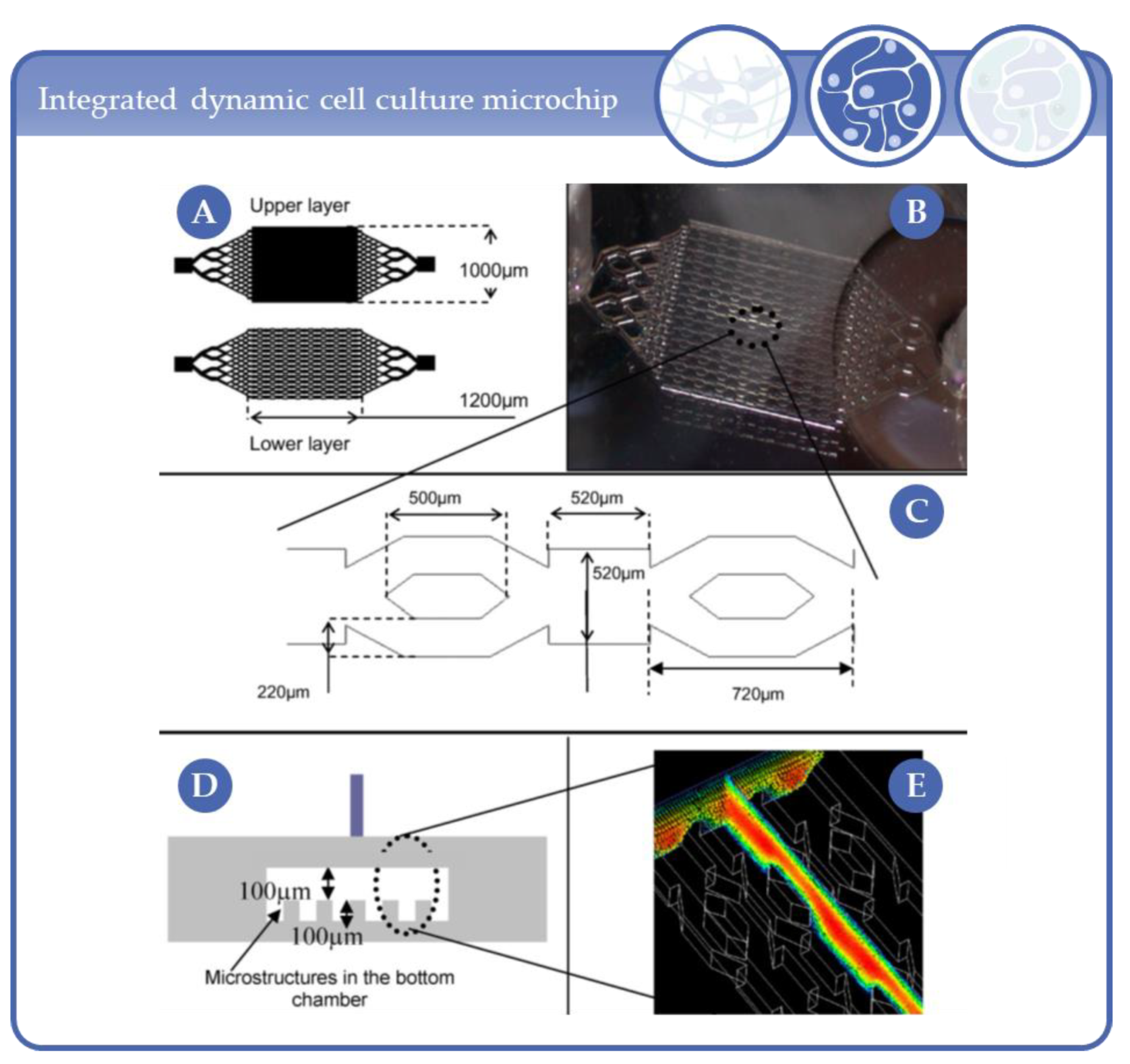
  196. Rieke, M.; Gottwald, E.; Weibezahn, K.-F.; Layer, P.G. Tissue reconstruction in 3D-spheroids from rodent retina in a motion-free, bioreactor-based microstructure. Lab Chip 2008, 8, 2206. [Google Scholar] [CrossRef]
  197. Gottwald, E.; Nies, C.; Wuchter, P.; Saffrich, R.; Truckenmüller, R.; Giselbrecht, S. A Microcavity Array-Based 3D Model System of the Hematopoietic Stem Cell Niche. Bioinform. MicroRNA Res. 2019, 2017, 85–95. [Google Scholar] [CrossRef]
  198. Radisic, M.; Marsano, A.; Maidhof, R.; Wang, Y.; Vunjak-Novakovic, G. Cardiac tissue engineering using perfusion bioreactor systems. Nat. Protoc. 2008, 3, 719–738. [Google Scholar] [CrossRef] [Green Version]
  199. Cheng, M.; Moretti, M.; Engelmayr, G.C.; Freed, L.E. Insulin-like Growth Factor-I and Slow, Bi-directional Perfusion Enhance the Formation of Tissue-Engineered Cardiac Grafts. Tissue Eng. Part A 2009, 15, 645–653. [Google Scholar] [CrossRef] [Green Version]
  200. Kenar, H.; Kose, G.T.; Toner, M.; Kaplan, D.L.; Hasirci, V. A 3D aligned microfibrous myocardial tissue construct cultured under transient perfusion. Biomaterials 2011, 32, 5320–5329. [Google Scholar] [CrossRef] [Green Version]
  201. Zhou, W.; Chen, Y.; Roh, T.; Lin, Y.; Ling, S.; Zhao, S.; Lin, J.D.; Khalil, N.; Cairns, D.M.; Manousiouthakis, E.; et al. Multifunctional Bioreactor System for Human Intestine Tissues. ACS Biomater. Sci. Eng. 2018, 4, 231–239. [Google Scholar] [CrossRef] [Green Version]
  202. Hoerstrup, S.P.; Zund, G.; Sodian, R.; Schnell, A.M.; Grünenfelder, J.; Turina, M.I. Tissue engineering of small caliber vascular grafts. Eur. J. Cardio-Thoracic Surg. 2001, 20, 164–169. [Google Scholar] [CrossRef] [Green Version]
  203. Pekor, C.; Gerlach, J.C.; Nettleship, I.; Schmelzer, E. Induction of Hepatic and Endothelial Differentiation by Perfusion in a Three-Dimensional Cell Culture Model of Human Fetal Liver. Tissue Eng. Part C Methods 2015, 21, 705–715. [Google Scholar] [CrossRef] [PubMed] [Green Version]
  204. Liu, X.-G.; Jiang, H.-K. Preparation of an osteochondral composite with mesenchymal stem cells as the single-cell source in a double-chamber bioreactor. Biotechnol. Lett. 2013, 35, 1645–1653. [Google Scholar] [CrossRef] [PubMed]
  205. Mahmoudifar, N.; Doran, P.M. Osteogenic differentiation and osteochondral tissue engineering using human adipose-derived stem cells. Biotechnol. Prog. 2012, 29, 176–185. [Google Scholar] [CrossRef] [PubMed]
  206. Kuiper, N.J.; Wang, Q.G.; Cartmell, S.H. A Perfusion Co-Culture Bioreactor for Osteochondral Tissue Engineered Plugs. J. Biomater. Tissue Eng. 2014, 4, 162–171. [Google Scholar] [CrossRef]
  207. Daley, E.L.; Kuttig, J.; Stegemann, J.P. Development of Modular, Dual-Perfused Osteochondral Constructs for Cartilage Repair. Tissue Eng. Part C Methods 2019, 25, 127–136. [Google Scholar] [CrossRef]
  208. Daneshgar, A.; Tang, P.; Remde, C.; Lommel, M.; Feufel, M.A.; Kertzscher, U.; Klein, O.; Weinhart, M.; Pratschke, J.; Sauer, I.M.; et al. Teburu—Open source 3D printable bioreactor for tissue slices as dynamic three-dimensional cell culture models. Artif. Organs 2019, 43, 1035–1041. [Google Scholar] [CrossRef]
  209. Song, J.J.; Guyette, J.P.; E Gilpin, S.; Gonzalez, G.A.; Vacanti, J.P.; Ott, H.C. Regeneration and experimental orthotopic transplantation of a bioengineered kidney. Nat. Med. 2013, 19, 646–651. [Google Scholar] [CrossRef]
  210. Song, L.; Zhou, Q.; Duan, P.; Guo, P.; Li, D.; Xu, Y.; Li, S.; Luo, F.; Zhang, Z. Successful Development of Small Diameter Tissue-Engineering Vascular Vessels by Our Novel Integrally Designed Pulsatile Perfusion-Based Bioreactor. PLoS ONE 2012, 7, e42569. [Google Scholar] [CrossRef] [Green Version]
  211. Aizawa, M.; Matsuura, T.; Zhuang, Z. Syntheses of Single-Crystal Apatite Particles with Preferred Orientation to the a- and c-Axes as Models of Hard Tissue and Their Applications. Biol. Pharm. Bull. 2013, 36, 1654–1661. [Google Scholar] [CrossRef] [Green Version]
  212. Gerlach, J.; Mutig, K.; Sauer, I.M.; Schrade, P.; Efimova, E.; Mieder, T.; Naumann, G.; Grunwald, A.; Pless, G.; Mas, A.; et al. Use of primary human liver cells originating from discarded grafts in a bioreactor for liver support therapy and the prospects of culturing adult liver stem cells in bioreactors: A morphologic study. Transplantation 2003, 76, 781–786. [Google Scholar] [CrossRef]
  213. Esch, E.W.; Bahinski, A.; Huh, D. Organs-on-chips at the frontiers of drug discovery. Nat. Rev. Drug Discov. 2015, 14, 248–260. [Google Scholar] [CrossRef] [PubMed] [Green Version]
  214. Huh, D.; Matthews, B.D.; Mammoto, A.; Montoya-Zavala, M.; Hsin, H.Y.; Ingber, D.E. Reconstituting Organ-Level Lung Functions on a Chip. Science 2010, 328, 1662–1668. [Google Scholar] [CrossRef] [PubMed] [Green Version]
  215. Bein, A.; Shin, W.; Jalili-Firoozinezhad, S.; Park, M.H.; Sontheimer-Phelps, A.; Tovaglieri, A.; Chalkiadaki, A.; Kim, H.J.; Ingber, D.E. Microfluidic Organ-on-a-Chip Models of Human Intestine. Cell. Mol. Gastroenterol. Hepatol. 2018, 5, 659–668. [Google Scholar] [CrossRef] [PubMed] [Green Version]
  216. Ramadan, Q.; Zourob, M. Organ-on-a-chip engineering: Toward bridging the gap between lab and industry. Biomicrofluidics 2020, 14, 041501. [Google Scholar] [CrossRef]
  217. Baert, Y.; Ruetschle, I.; Cools, W.; Oehme, A.; Lorenz, A.; Marx, U.; Goossens, E.; Maschmeyer, I. A multi-organ-chip co-culture of liver and testis equivalents: A first step toward a systemic male reprotoxicity model. Hum. Reprod. 2020, 35, 1029–1044. [Google Scholar] [CrossRef]
  218. Zhang, Y.S.; Arneri, A.; Bersini, S.; Shin, S.-R.; Zhu, K.; Goli-Malekabadi, Z.; Aleman, J.; Colosi, C.; Busignani, F.; Dell’Erba, V.; et al. Bioprinting 3D microfibrous scaffolds for engineering endothelialized myocardium and heart-on-a-chip. Biomaterials 2016, 110, 45–59. [Google Scholar] [CrossRef] [Green Version]
  219. Ahadian, S.; Civitarese, R.; Bannerman, D.; Mohammadi, M.H.; Lu, R.; Wang, E.; Davenport-Huyer, L.; Lai, B.; Zhang, B.; Zhao, Y.; et al. Organ-On-A-Chip Platforms: A Convergence of Advanced Materials, Cells, and Microscale Technologies. Adv. Heal. Mater. 2018, 7, 7. [Google Scholar] [CrossRef]
  220. Park, D.; Lee, J.; Chung, J.J.; Jung, Y.; Kim, S.H. Integrating Organs-on-Chips: Multiplexing, Scaling, Vascularization, and Innervation. Trends Biotechnol. 2020, 38, 99–112. [Google Scholar] [CrossRef]
  221. Ronaldson-Bouchard, K.; Vunjak-Novakovic, G. Organs-on-a-Chip: A Fast Track for Engineered Human Tissues in Drug Development. Cell Stem Cell 2018, 22, 310–324. [Google Scholar] [CrossRef] [Green Version]
  222. Sosa-Hernández, J.E.; Villalba-Rodríguez, A.M.; Romero-Castillo, K.D.; Aguilar-Aguila-Isaías, M.A.; García-Reyes, I.E.; Hernández-Antonio, A.; Ahmed, I.; Sharma, A.; Parra-Saldívar, R.; Iqbal, H.M. Organs-on-a-Chip Module: A Review from the Development and Applications Perspective. Micromachines 2018, 9, 536. [Google Scholar] [CrossRef] [Green Version]
  223. Terrell, J.A.; Jones, C.G.; Kabandana, G.K.M.; Chen, C. From cells-on-a-chip to organs-on-a-chip: Scaffolding materials for 3D cell culture in microfluidics. J. Mater. Chem. B 2020, 8, 6667–6685. [Google Scholar] [CrossRef] [PubMed]
  224. Azizipour, N.; Avazpour, R.; Rosenzweig, D.H.; Sawan, M.; Ajji, A. Evolution of Biochip Technology: A Review from Lab-on-a-Chip to Organ-on-a-Chip. Micromachines 2020, 11, 599. [Google Scholar] [CrossRef] [PubMed]
  225. Tang, H.; Abouleila, Y.; Si, L.; Ortega-Prieto, A.M.; Mummery, C.L.; Ingber, D.E.; Mashaghi, A. Human Organs-on-Chips for Virology. Trends Microbiol. 2020, 28, 934–946. [Google Scholar] [CrossRef] [PubMed]
  226. Klak, M.; Bryniarski, T.; Kowalska, P.; Gomolka, M.; Tymicki, G.; Kosowska, K.; Cywoniuk, P.; Dobrzanski, T.; Turowski, P.; Wszoła, M. Novel Strategies in Artificial Organ Development: What is the Future of Medicine? Micromachines 2020, 11, 646. [Google Scholar] [CrossRef] [PubMed]
  227. Allwardt, V.; Ainscough, A.J.; Viswanathan, P.; Sherrod, S.D.; McLean, J.A.; Haddrick, M.; Pensabene, V. Translational Roadmap for the Organs-on-a-Chip Industry toward Broad Adoption. Bioengineering 2020, 7, 112. [Google Scholar] [CrossRef] [PubMed]
  228. Materne, E.-M.; Ramme, A.P.; Terrasso, A.P.; Serra, M.; Alves, P.M.; Brito, C.; Sakharov, D.A.; Tonevitsky, A.; Lauster, R.; Marx, U. A multi-organ chip co-culture of neurospheres and liver equivalents for long-term substance testing. J. Biotechnol. 2015, 205, 36–46. [Google Scholar] [CrossRef]
  229. Schimek, K.; Frentzel, S.; Luettich, K.; Bovard, D.; Rütschle, I.; Boden, L.; Rambo, F.; Erfurth, H.; Dehne, E.-M.; Winter, A.; et al. Human multi-organ chip co-culture of bronchial lung culture and liver spheroids for substance exposure studies. Sci. Rep. 2020, 10, 1–13. [Google Scholar] [CrossRef]
  230. van den Berg, A.; Mummery, C.L.; Passier, R.; Van Der Meer, A.D. Personalised organs-on-chips: Functional testing for precision medicine. Lab Chip 2018, 19, 198–205. [Google Scholar] [CrossRef] [Green Version]
  231. Geraili, A.; Jafari, P.; Hassani, M.S.; Araghi, B.H.; Mohammadi, M.H.; Ghafari, A.M.; Tamrin, S.H.; Modarres, H.P.; Kolahchi, A.R.; Ahadian, S.; et al. Controlling Differentiation of Stem Cells for Developing Personalized Organ-on-Chip Platforms. Adv. Heal. Mater. 2017, 7, 1700426. [Google Scholar] [CrossRef] [Green Version]
  232. Smirnova, L.; Kleinstreuer, N.; Corvi, R.; Levchenko, A.; Fitzpatrick, S.C.; Hartung, T. 3S—Systematic, systemic, and systems biology and toxicology. ALTEX 2018, 35, 139–162. [Google Scholar] [CrossRef] [Green Version]
  233. Ferrari, E.; Palma, C.; Vesentini, S.; Occhetta, P.; Rasponi, M. Integrating Biosensors in Organs-on-Chip Devices: A Perspective on Current Strategies to Monitor Microphysiological Systems. Biosensors 2020, 10, 110. [Google Scholar] [CrossRef] [PubMed]
  234. Low, L.A.; Mummery, C.; Berridge, B.R.; Austin, C.P.; Tagle, D.A. Organs-on-chips: Into the next decade. Nat. Rev. Drug Discov. 2020, 1–17. [Google Scholar] [CrossRef] [PubMed]
  235. Fetah, K.L.; DiPardo, B.J.; Kongadzem, E.; Tomlinson, J.S.; Elzagheid, A.; Elmusrati, M.; Khademhosseini, A.; Ashammakhi, N. Cancer Modeling-on-a-Chip with Future Artificial Intelligence Integration. Small 2019, 15, e1901985. [Google Scholar] [CrossRef] [PubMed]
  236. Swayden, M.; Soubeyran, P.; Iovanna, J. Upcoming Revolutionary Paths in Preclinical Modeling of Pancreatic Adenocarcinoma. Front. Oncol. 2020, 9, 1443. [Google Scholar] [CrossRef]
  237. Williams, K.A.; Saini, S.; Wick, T.M. Computational Fluid Dynamics Modeling of Steady-State Momentum and Mass Transport in a Bioreactor for Cartilage Tissue Engineering. Biotechnol. Prog. 2002, 18, 951–963. [Google Scholar] [CrossRef]
  238. Sucosky, P.; Osorio, D.F.; Brown, J.B.; Neitzel, G.P. Fluid mechanics of a spinner-flask bioreactor. Biotechnol. Bioeng. 2004, 85, 34–46. [Google Scholar] [CrossRef]
  239. Yu, P.; Lee, T.; Zeng, Y.; Low, H. A 3D analysis of oxygen transfer in a low-cost micro-bioreactor for animal cell suspension culture. Comput. Methods Programs Biomed. 2007, 85, 59–68. [Google Scholar] [CrossRef]
  240. Tajsoleiman, T.; Abdekhodaie, M.J.; Gernaey, K.V.; Krühne, U. Efficient Computational Design of a Scaffold for Cartilage Cell Regeneration. Bioengineering 2018, 5, 33. [Google Scholar] [CrossRef] [Green Version]
  241. Magrofuoco, E.; Elvassore, N.; Doyle, F.J. Theoretical analysis of insulin-dependent glucose uptake heterogeneity in 3D bioreactor cell culture. Biotechnol. Prog. 2012, 28, 833–845. [Google Scholar] [CrossRef]
  242. Porter, B.; Zauel, R.; Stockman, H.; Guldberg, R.; Fyhrie, D. 3-D computational modeling of media flow through scaffolds in a perfusion bioreactor. J. Biomech. 2005, 38, 543–549. [Google Scholar] [CrossRef]
  243. Raimondi, M.T.; Moretti, M.; Cioffi, M.; Giordano, C.; Boschetti, F.; Laganà, K.; Pietrabissa, R. The effect of hydrodynamic shear on 3D engineered chondrocyte systems subject to direct perfusion. Biorheology 2006, 43, 215–222. [Google Scholar] [PubMed]
  244. Hyndman, L.; McKee, S.; Mottram, N.J.; Singh, B.; Webb, S.D.; McGinty, S. Mathematical modelling of fluid flow and solute transport to define operating parameters for in vitro perfusion cell culture systems. Interface Focus 2020, 10, 20190045. [Google Scholar] [CrossRef] [PubMed] [Green Version]
  245. Lee, P.S.; Eckert, H.; Hess, R.; Gelinsky, M.; Rancourt, D.; Krawetz, R.; Cuniberti, G.; Scharnweber, D. Developing a Customized Perfusion Bioreactor Prototype with Controlled Positional Variability in Oxygen Partial Pressure for Bone and Cartilage Tissue Engineering. Tissue Eng. Part C Methods 2017, 23, 286–297. [Google Scholar] [CrossRef] [PubMed]
  246. Chang, R.; Nam, J.; Sun, W. Direct Cell Writing of 3D Microorgan for In Vitro Pharmacokinetic Model. Tissue Eng. Part C Methods 2008, 14, 157–166. [Google Scholar] [CrossRef]
  247. Zhao, F.; Chella, R.; Ma, T. Effects of shear stress on 3-D human mesenchymal stem cell construct development in a perfusion bioreactor system: Experiments and hydrodynamic modeling. Biotechnol. Bioeng. 2006, 96, 584–595. [Google Scholar] [CrossRef]
  248. Hassan, C.R.; Qin, Y.; Komatsu, D.E.; Uddin, S.M.Z. Utilization of Finite Element Analysis for Articular Cartilage Tissue Engineering. Materials 2019, 12, 3331. [Google Scholar] [CrossRef] [Green Version]
  249. Raies, B.A.; Bajic, V.B. In silicotoxicology: Computational methods for the prediction of chemical toxicity. Wiley Interdiscip. Rev. Comput. Mol. Sci. 2016, 6, 147–172. [Google Scholar] [CrossRef] [Green Version]
  250. Jean-Quartier, C.; Jeanquartier, F.; Jurisica, I.; Holzinger, A. In silico cancer research towards 3R. BMC Cancer 2018, 18, 1–12. [Google Scholar] [CrossRef]
Figure 1. For a better overview of the discussed micro-bioreactors (MBR) systems and the corresponding complexity levels the depicted icons are given in the particular sections.
Processes 09 00021 g001
Figure 2. Examples of MBRs for mechanical stimulation established for (A) the application of ligament-like multidimensional mechanical strains; the arrow indicates a collagen gel suspended between two bone anchors as it is stimulated translationally and torsionally. Reprinted from [6] with permission of John Wiley and Sons. (B) The application of physiological shear and pulsatile conditioning of vascular in vitro-constructs in a pulsatile flow bioreactor; a schematic of the system design, which includes (1) one or more pulsatile pumps, (2) custom graft chamber, (3) media reservoir, (4) a peristaltic pump, (5) compliance chamber, (6) check valves; close up of the graft chamber and representative pressure waveforms. Reprinted with permission from [8]. (C) Application of biaxial stretch to fibroblast-seeded cruciform shaped gels. Reprinted from [11] with permission of Elsevier.
Processes 09 00021 g002
Figure 3. MBR with perfusion chambers and closed circulation loop for improved nutrient supply. Silicon tubes connected two spatial separated bioreactor compartments in one common system. The pump performs the medium perfusion between compartments with possibility for variable flow and pulsation rate. The multiple inputs and outputs permit optimized medium flow distribution. Reprinted from [14] with permission of Elsevier.
Processes 09 00021 g003
Figure 4. Steps in the development of miniaturized and parallelized microfluidic MBRs; Microfluidic platform with 5 MBRs. Reprinted with permission from [17] with permission from Springer Nature. (B) Schematic diagram showing the set-up of the parallel perfused bioreactor system with 12 micro-bioreactors. Each microbioreactor is individually supplied with culture medium through a multi-channel peristaltic pump. The effluents downstream can be collected individually. Reprinted from [18] with permission of Elsevier. (C) The assembly of the perfusion-based micro 3D cell culture platform including 30 MBRs and cross-sectional view of the laminate structure. Reprinted with permission from [19] from Springer Nature.
Processes 09 00021 g004
Figure 5. Microfluidic MBRs with microchannels fabricated by: (A) molding of cell laden agarose gels into patterned silicon wafers; reprinted from Ling et al. [20] with permission of the Royal Society of Chemistry, permission conveyed through Copyright Clearance Center, Inc. or (B) bioprinting of alginate encapsulated cells into glass etched channels; reprinted from Chang et al. [21] with permission from Springer Nature.
Processes 09 00021 g005
Figure 6. Advanced development of miniaturized MBRs for HTS applications. (A) MBR platform with 16 cell culture sections comprising three MBRs; reprinted from [31] with permission from Springer Nature. (B) MBR platform with integrated “plug module” to facilitate the production of cell laden hydrogel constructs; reprinted from [30] with permission form Springer Nature. (C) MBR platform with integrated waste medium collector module compatible with a plate reader for bioassays; reprinted from [32] with permission of the Royal Society of Chemistry, permission conveyed through Copyright Clearance Center, Inc.
Processes 09 00021 g006
Figure 7. Latest MBR types and approaches. (A) Miniaturized MBR for mechanical compressive loading of cells in hydrogels; reprinted from [35] with permission from Springer Nature. (B) MBR with channels divided by an array of S-shaped micropillars which allow the formation and maintenance of molecule gradients for chemotaxis experiments; reprinted from [37] with permission of AIP Publishing. (C) MBR with microfluidic networks in cell laden gels casted between an acrylic casing and a PDMS mold for active perfusion to generate thick and robust tissue engineering(TE)-constructs; reprinted from [36] with permission of John Wiley and Sons. (D) MBR with magnetic cell-laden hydrogels for contactless movement of the gel-based constructs by an external magnetic field; Reprinted from [39] with permission of John Wiley and Sons.
Processes 09 00021 g007
Figure 8. Diagram of two types of rotating wall vessel (RWV) bioreactors. (A) Slow turning lateral vessel (STLV) for formation of smaller cell aggregates (in this case small human embryoid bodies). (B) Usage of a high aspect rotating vessel (HARV) bioreactor leads to agglomeration of big cellular clumps. Reprinted from [45] with permission of John Wiley and Sons.
Processes 09 00021 g008
Figure 9. (A) MBR and microcavity array. Typical arrays of a 1 × 1 cm2 area consist of 634 microcavities with 300 µm diameter and 250 µm depth. (B) Schematic representation of the microcavity array-based bioreactor closed circulation loop comprising the bioreactor, a medium reservoir and a cassette pump.
Processes 09 00021 g009
Figure 10. Micro-hollow fiber bioreactor for high-density liver cell culture. Media capillaries in red and blue and oxygenation capillaries in yellow. The lower inserts show microscopic pictures (30-fold magnification) of the capillary bed before inoculation (a) and immediately after cell inoculation, revealing a homogenous distribution of the inoculated cell suspension between the capillaries (b). Right: Bioreactor operation in an electronically controlled perfusion device equipped with pumps for medium recirculation and medium feed, temperature control and with a valve-regulated gas mixing unit. Perfusion parameters are automatically monitored and can be regulated via an integrated touch screen Reprinted from [104] with permission of John Wiley and Sons.
Processes 09 00021 g010
Figure 11. Pipe based micro-bioreactor (PBM) overview and basic set up with the capability of generating embryoid bodies by segmented flow. (A) Principle of gas exchange between PBM and an environment; (B) basic setup placed under a clean bench; (C) two capillary probe for 800 nL droplet generation within 1 mm coil (left hand side) and the 1 mm coil for cultivation of cells (right hand side). The enlarged section of the right hand side picture shows the droplets inside the PTFE tube. Reprinted with permission from [117]. Copyright © 2016, Karger Publishers.
Processes 09 00021 g011
Figure 12. Slide-format based PDMS chip for on-chip generation of spheroids and integrated multiscale cytometry. Reprinted from Sart et al., Nat. Commun. 2017; 8(1):469 [119].
Processes 09 00021 g012
Figure 13. Schematic of the perfusion incubator liver chip (PIC) chip. (A) 3D view with the PIC. A glass/silicon structure containing a 3D microfluidic circuit, the cell culture chamber, a bubble trap chamber as well as a heater. (B) Bottom view of the chip’s layout illustrating the microfluidic circuit, the cell culture chamber, the bubble trap and the heater. (C) Cross-section of the PIC illustrating the structure of the bubble trap. It consists of a 70 μm-thick PDMS membrane (gas permeable) bonded to a PDMS molded chamber with pillars that support the membrane. The PDMS structure is connected to external vacuum (through a pressure controller). The gas bubbles trapped in the microwell can diffuse through the PDMS membrane due to negative pressure in the vacuum chamber while culture media remains inside the culture chamber. (D) Top and bottom view of the PIC. Reprinted from [126] with permission of Elsevier.
Processes 09 00021 g013
Figure 14. Flowchart of U-shaped microstructure fabrication, cell trapping, and spheroid formation. Reprinted from [127]; © IOP Publishing. Reproduced with permission. All rights reserved.
Processes 09 00021 g014
Figure 15. (A) Microfluidic analysis platform (MAP) for the 3D cultivation of pancreatic islets. A total of 110 islets can be loaded into one platform. Reprinted from [130] with permission of John Wiley and Sons. (B) Left: MBR seeded with embryoid bodies. Right: Magnification of individual microwells. Republished with permission of the Royal Society of Chemistry from [131]; permission conveyed through Copyright Clearance Center, Inc.
Processes 09 00021 g015
Figure 16. (A) Design of the integrated dynamic cell culture microchip (IDCCM) with the photomasks used to fabricate the mold masters, (B) the PDMS bioreactor, (C) the microchannel design, (D) a bioreactor cross section, (E) and the velocity profile in the bioreactor. Reprinted from [142] with permission of Elsevier.
Processes 09 00021 g016
Figure 17. Integrated automated multiorgan-on-a-chip and sensing platform. (A) Schematic of a full system where the multiorgan-on-a-chip platform was encased in an in-house designed benchtop incubator, and of automated pneumatic valve controller, electronics for operating physical sensors, potentiostat for measuring electrochemical signals, and computer for central programmed integration of all of the commands. (B) Schematic of the integrated microfluidic device consisting of modular components including microbioreactors, breadboard, reservoir, bubble trap, physical sensors, and electrochemical biosensors. Inset shows the photograph of an integrated platform. Schematic view of the integrated multiorgan-on-a-chip system with different micro-bioreactor modules. Reprinted from Zhang et al., PNAS 2017; 114(12):E2294 [159].
Processes 09 00021 g017
Figure 18. Top: Computer-aided design of the 12-well miniaturized stirred bioreactor (SpinΩ), consisting of a motor and gears for the 12 spinning shafts and leafs. Bottom: Scheme of the protocol for forebrain organoid development in the SpinΩ and microscopy images at different stages of development. Scale bars: 200 µm. Reprinted from [176] with permission from Elsevier.
Processes 09 00021 g018
Figure 19. Colon carcinoma cell growth inside liver tumor organoids. (A) Scheme of liver tumor organoid formation in an RWV bioreactor. (B) MSCs supporting organoid formation. (C) Formation of liver tumor organoids including MSCs. Reproduced from [180] with permission ® IOP Publishing. All rights reserved.
Processes 09 00021 g019
Figure 20. (A) Left: U-shaped trap-like features in a patterned PDMS chip for on-chip cultivation and perfusion of cell-aggregates. Center: Simulation of fluid flow through the trap-like features of 500 µm. Right: Aggregates of hepatocytes and 3T3-J3 fibroblasts under perfusion with 24 µL/h respectively 500 µL/h. Republished with permission of the Royal Society of Chemistry from [186] (B) Chip of Mauleon et al. for spatial and temporal control of oxygen within brain slices. The sketch displays the modified standard perfusion chamber with a micro-structured PDMS membrane, including support pillars, for oxygen distribution. Reprinted from [189]. (C) Schematic illustration of the microfluidic cell migration assay with a control channel (top) and a channel for conditioned media respectively cells (bottom). The microscope images show the application of the chip for the co-cultivation of HMVEC with U87MG respectively 10T1/2 and the resulting migration of the cells into collagen-gels. Republished with permission of the Royal Society of Chemistry from [190].
Processes 09 00021 g020
Figure 21. Left: 3D cell culture plate in a 384-well format for 40 three-lane culture chambers. Center: Schematic illustration of a mixed co-culture and adjacent co-culture. Right: Bright light microscopy of the mixed and adjacent co-culture of HepG2 cells and 3T3 fibroblasts. Mixed co-culture leads to tighter aggregates (see white arrows), reprinted from [195] with permission from RSC Publishing.
Processes 09 00021 g021
Figure 22. (A) Microfluidic bioreactor of Hwa et al. for both, perfusion and superfusion of cells in silicon scaffolds. The optical window allows for microscopy during experiments. (B) SEM of 3-day old microreactor co-cultures or rat liver sinusoidal endothelial cells with hepatocytes. (C) Immunohistochemistry of the co-cultures. Reprinted from [174] with permission of John Wiley and Sons.
Processes 09 00021 g022
Figure 23. (A) Stirred and fluidic superfusion bioreactor of Liu et al. (B) Chondral (left) and osseous phase (right) of the biphasic scaffold used in (A). Reprinted from [204] with permission of Springer Nature (C) Bioreactor system of Mahmoudifar and Doran consisting of two separate culture chambers containing osteogenic respectively chondrogenic medium (left). Up to three triplicate PGA disk scaffolds can be mounted between the two chambers (right). This allows the surface of the scaffolds to contact the two differentiation media for development of osteochondral tissues. Reprinted from [205] with permission of John Wiley and Sons.
Processes 09 00021 g023
Figure 24. (A) Drawing of an integrated OoC system for disposable organ chips. Reprinted from [216] with permission of AIP Publishing. (B) Left: Sketch of an three organ chip. Center: Exploded view, showing the components and connectors. Right: The microfluidic layout of the chip, including channels, cell culture compartments and an on-chip micro-pump. Reprinted from [217] with permission of Oxford University Press.
Processes 09 00021 g024
Figure 25. Icons for the classification of publications with a simulation component. Left: the icon for in vitro experiments in addition to the simulations, right: the icon for publications that use simulations or computational methods.
Processes 09 00021 g025
Figure 26. (A) Different experimental approaches (dimensions are in μm): (1) horizontal toroid in a U-shaped barrier; (2) vertical toroid in a U-shaped barrier; (3) spheroid in a U-shaped barrier; (4) toroid; (5) spheroid; (6) horizontal toroid in a microwell; (7) vertical toroid in a microwell and (8) spheroid in a microwell. Reprinted from [128] with permission from MDPI. (B) Simulation results of the different traps, i.e., (1) microwell structure; (2) integrated U-shaped barrier and (3) U-shaped barrier created with microposts, on the oxygen (4–6) and glucose (7–9) concentration distribution inside the spheroid and maximum shear stress on its surface (5) the proliferating, quiescent and necrotic zones due to oxygen deficiency in the middle x–z plane of the spheroid in the microwell, (6, 7) oxygen concentration distribution in the middle x–z plane of the spheroid in the integrated U-shaped barrier and U-shaped barrier created with microposts, respectively, (8, 9) the proliferating, quiescent and necrotic zones due to glucose deficiency in the middle x–z plane of the spheroid in the microwell, U-shaped barrier and U-shaped barrier created with microposts, respectively. Reprinted from [129] with permission from MDPI.
Processes 09 00021 g026
Figure 27. Local shear stress field: map of shear stresses (Pa) in media transversely perfused through a 3D trabecular bone scaffold from side and top views. Reprinted from [242] with permission of Elsevier.
Processes 09 00021 g027
Figure 28. Simulation results for Q = 100 mL min−1. (A) Streamlines and magnitude of velocity through the center of the chamber on the y,z-plane. (B) Magnitude of velocity through the center of the chamber on the y,z-plane using a log scale. (C) Magnitude of shear stress at the cell surface on the x,y-plane. Reprinted with permission from [244] by Royal Society Publishing.
Processes 09 00021 g028
Table 1. Abbreviations appearing in the text.
µCTMicro Computed Tomography
5-FU5-fluoruracil
ALPalkaline phosphatase
BBBblood-brain-barrier
BCTbioartificial cardiac tissue
CFDcomputational fluidic dynamics
cfDNAcell free DNA
CVBcoxsackievirus B
ECMextracellular matrix
FEAfinite element analysis
HARVhigh aspect ratio vessel
hASCshuman adipose stem cells
hBMCshuman bone marrow cells
HCVhepatitis C virus
hEBhuman embryoid bodies
hMSCshuman mesenchymal stem cells
HNCshuman nasal chondrocytes
HSPCshematopoietic stem/progenitor cells
HTShigh-throughput-screening
IDCCMintegrated dynamic cell culture microchip
iPSCinduced pluripotent stem cells
LBLattice-Boltzmann
LSECliver sinusoidal endothelial cells
MAPmicrofluidic analysis platform
MBRmicro-bioreactor
MOABmagnetic optically assessible bioreactor
MPPSmicro-pathophysiological systems
MRImagnetic resonance imaging
NASAnational aeronautics and space administration
OoCorgan-on-a-chip
PBMpipe based microbioreactor
PDMSpolydimethylsiloxan
PEGpolyethylen glycol
PEGDApoly(ethylene glycol) diacrylate
PETpolyethylene terephtalate
PGApolyglycolic acid
PGSpoly(glycerol sebacetate)
PICperfusion incubator liver chip
PLApoly(lactic acid)
PLGApoly(lactic-co-glycolic acid)
PLLApoly(L-lactic acid)
PTFEpolytetrafluorethene
PUpolyurethane
RCCSrotary cell culture system
ROSreactive oxygen species
RWVrotating wall vessel
SEMscanning electron microscope
SEVA-Cblend of starch with ethylene vinyl alcohol
SPCLblend of starch with poly(ε-caprolactone)
STLVslow turning lateral vessel
TEtissue engineering
TLAtissue-like assemblies
ZIKVZika virus
Publisher’s Note: MDPI stays neutral with regard to jurisdictional claims in published maps and institutional affiliations.

