1. Introduction
The use of hazardous materials has rapidly increased due to the advent of new high-tech industries and the growth of traditional industries. Accordingly, the likelihood of major accidents has also increased. Among the various major chemical accidents, vessel leakage or rupture is one of the main root causes of catastrophic events and can lead to triggering hazardous material dispersion, fire and explosion [
1]. The Fixborough disaster in England in 1974 [
2], and a toxic gas release in Seveso, Italy, in 1978 [
3] are representative examples of a material release from vessels. Furthermore, the huge explosion of ammonium nitrate in Beirut’s port (August in 2020) killed at least 181 people [
4]. In the case of South Korea, the leakage accident of HF (hydrogen fluoride) in Gumi in 2012 caused a lot of damage around a residential area and this has become a major turning point in the field of chemical process safety in South Korea. Later, two regulations (the Act on registration, evaluation, etc., of chemicals and the Chemical substances control Act) were enacted in 2018.
Additionally, the government has increased the supervision of the monitoring of chemical plants and recommended worksites to install mitigation equipment or systems to minimize the impact of accidents. However, the lack of information regarding the performance of mitigation systems makes it difficult to adopt and install them.
In the last few decades, there have been a few studies that verified the performance of mitigation systems. There are two main methods for evaluating the performance of mitigation systems. The first is a set of experiments. Rana, M. A. et al. tested two water curtain systems to identify the effectiveness of liquefied natural gas (LNG) release [
5]. Suardin, J. A. et al. tested fire suppression materials to reduce the radian heat of an LNG pool fire [
6]. However, to test these mitigation systems, sufficient space is required and many serious risks should be considered. Therefore, these experiments cannot be conducted at the level of academic laboratories.
As an alternative method to experiments, computational simulations have been gaining more popularity. Lim, H.Y. et al. measured the effectiveness of physical barriers when HF and chlorine are leaked [
7]. Prashanth, I. et al. simulated the performance of a safety barrier for onshore gas drilling operations [
8]. Busini, V. and Rota, R. simulated the mitigation barriers to interrupt the travel of LNG using computational fluid dynamics (CFDs) [
9]. Liu, D. and Wei, J. simulated continuous dense gas leakage based on a modified plate model [
10]. Most simulation-based studies have employed computational fluid dynamics (CFDs) and to focus on the gas dispersion and how mitigation systems interrupt the travel of a gas.
In our previous study [
11], a mitigation system in which a reserve vessel is installed next to a storage vessel was proposed. In this system, two vessels are connected with a pipe and the chemical material in a storage vessel is moved to a reserve vessel by a pump when leakage occurs, reducing the amount of leakage. However, the dangerous materials that can leak to the outside should be handled properly. The NFPA (National Fire Protection Association) 30 code provides a remote impounding system as a secondary containment [
12]. The material leaked to the outside is transferred to a remote impoundment by an adequate draining path. The volume of the remote impoundment must be larger than that of the storage vessel to contain all the materials. However, in the case of South Korea, securing a sufficient site for installing a large remote impoundment inside an existing plant is rarely feasible. Therefore, in this study, a new mitigation system involving a reserve tank and a remote impoundment is introduced and simulated. To account for the lack of a site, this system can be operated by two pumps. The modeling of this system is based on the fluid dynamics equations and the proper design specifications such as pump capacities are investigated. This study aims to provide guidelines how to determine design specifications of the proposed mitigation system based on the mathematical modeling.
This paper is organized as follows. In
Section 2, the description and the basic modeling of a new mitigation system are explained.
Section 3 and
Section 4 show the results of the case studies and the consequence analysis under this mitigation system. The final section presents the conclusion.
2. The Mathematical Modeling of a Leakage and a Mitigation System
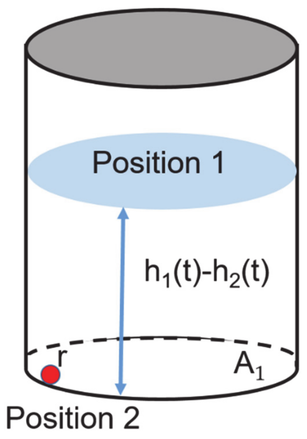
This study proposes a mitigation system for handling liquid leakage. It is assumed that there are no phase transitions during a leakage, i.e., the vaporization of a fluid is excluded, since the maximum amount of leakage should be considered to determine the specifications of a mitigation system. Furthermore, the vessel type is a vertical cylindrical. Before a mitigation system is designed, the fluid velocity through a leak hole of a vessel should be calculated.
Figure 1 shows the leakage of a vessel. Equation (1) represents the fundamental equation of Torricelli’s theorem based on the energy conservation law where
and
are the gravitational acceleration and the liquid density [
11].
and
are the velocity at the top of a fluid and a leak hole.
and
are the height of each position (Position 1 and Position 2) and
and
are the pressures at the top and the atmospheric pressure around a leak hole.
If
is the same as the change in fluid level per unit of time, then
can be represented by Equation (2) as;
When a leakage progresses, the empty space of a vessel also increases, thus the pressure (
) and the volume of inert gas are changed. To evaluate the change in
, Van der Waals’s equation (Equation (3)) is employed where
,
and
are the total volume, temperature and moles of the inert gas, respectively.
and
are parameters and
is an ideal gas constant. In general, the safety valve is installed for maintain the proper pressure in a storage vessel. However, it assumed that this is not installed in this study. The inert gas of a storage vessel is nitrogen and the moles of nitrogen can be calculated based on an initial vessel condition and it is assumed that the temperature of the empty space is constant.
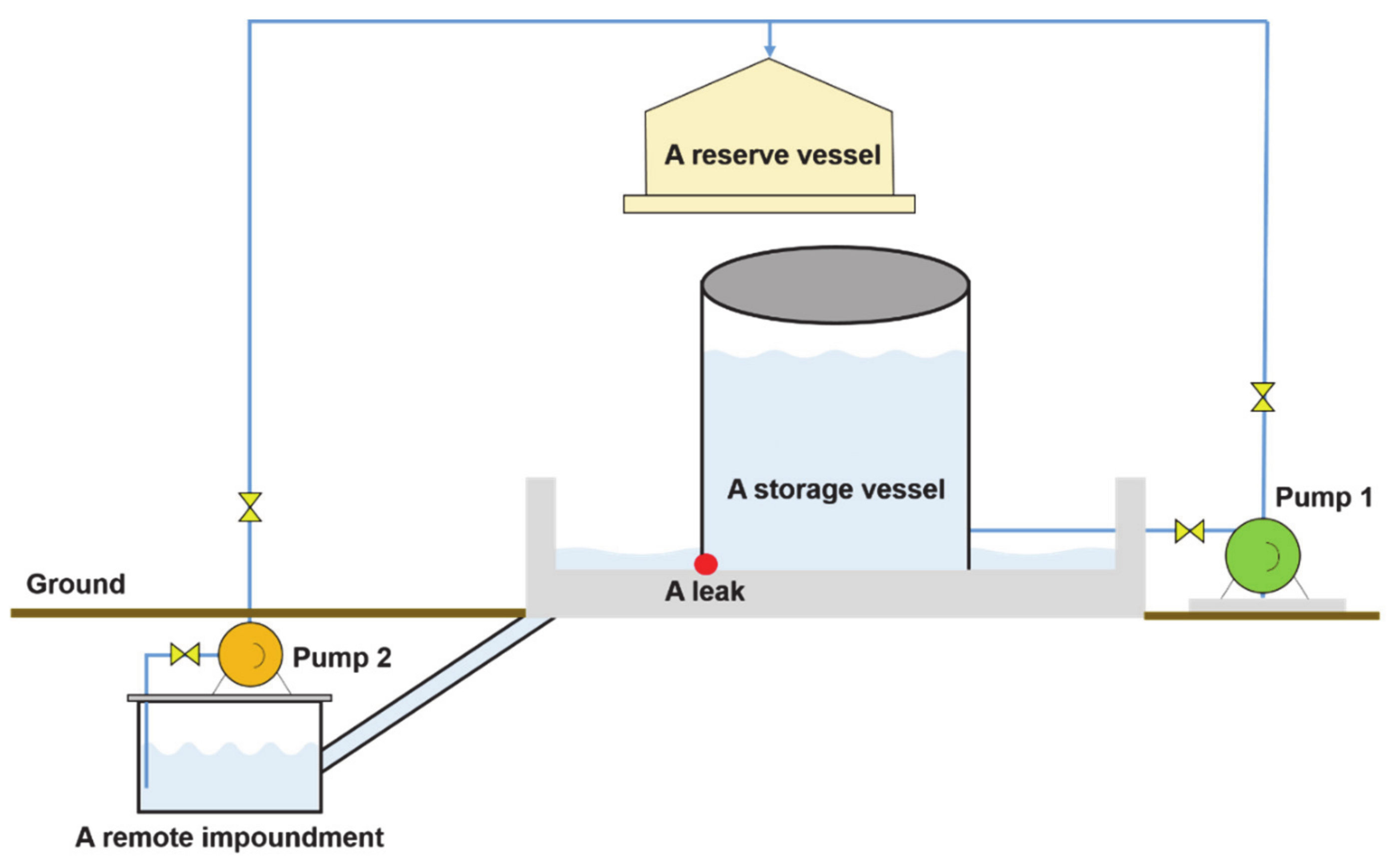
Figure 2 shows a diagram of the proposed mitigation system. A storage vessel is connected with a reserve tank. If leakage occurs, the chemical material in the storage vessel is automatically transferred to the reserve tank by a pump (Pump 1) throughout the level sensor for monitoring an abrupt change of a material in the vessel. Furthermore, the material that leaks to the outside is trapped in a dike. This flows to a remote impoundment along the drain path. Because of the lack of a site for storing all the material, the remote impoundment is also connected to the reserve tank and the fluid is transferred by another pump (Pump 2). Thus, there are two pumps and their optimal capacities should be evaluated through the consideration of the fixed conditions.
When
and
are the pump capacities, Equations (4) and (5) can be derived as;
In Equation (5), is the fluid level of the remote impoundment and the radius of the leak hole is . Since the material of the storage tank flows into the remote impoundment, there is a time delay, . In this study, by considering of the length of a drain path, is set to 2 s. is a unit step function and the value of this function is 1 if is positive, otherwise, the value is 0. This indicates that Pump 2 is only operated when the level of the remote impoundment is above 0.5 and this is the constraint for the protection of the pump facility. The key issue is that a pump should be operated safely and continuously. If the pump capacity is too excessive, the pump may turn off repeatedly and this can trigger a pump failure. Moreover, this system requires a control to prevent the overflow of the remote impoundment. Thus, to guarantee continuous operation and to control overflow, the optimal pump capacity should be investigated by considering an accident scenario. In this study, these differential equations were simulated in MATLABTM.
3. Case Studies
To verify the performance of the proposed mitigation system, two vessels are tested. To simulate, the following conditions should be previously determined.
The diameter and position of the leak hole;
The starting time of the mitigation system after a leak occurs;
The conditions of the atmosphere;
The operating conditions in the vessel.
The vessel specifications, leak properties, and other conditions are summarized in
Table 1. The position of the leak hole is at the bottom of a vessel, i.e., the height of the leak is 0 m. It is assumed that there is no time delay between the leak occurrence and the operation of the mitigation system. This implies that the mitigation system can be operated as soon as the accident occurs. These case studies aim to investigate the optimal pump capacities. In this study, the capacity of Pump 1 in
Figure 1 is fixed beforehand and that of Pump 2 should be investigated. A pump should transport a fluid as quickly as possible. Moreover, if the pump capacity is too large, the pump can be switched on and off repeatedly as mentioned earlier. Therefore, it is really important to determine the optimal capacity of Pump 2.
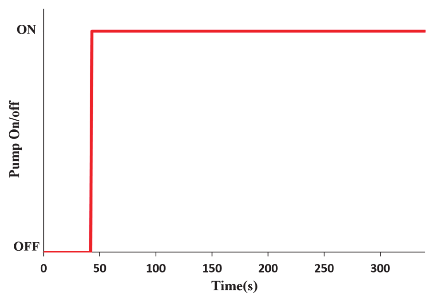
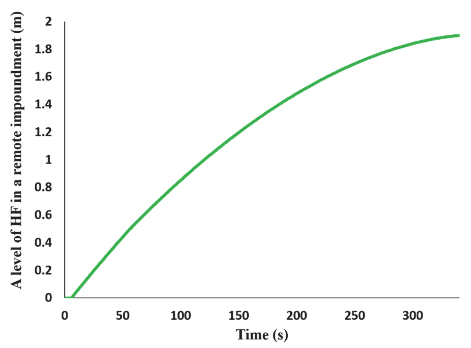
Figure 3,
Figure 4 and
Figure 5 shows the results for the HF leakage where the diameter of the leak hole is 6 inch and its height is 0 m.
Figure 3 shows the level of the HF in the remote impoundment when the capacity of Pump 2 is 50 m
3/h which is the optimal and smallest capacity to prevent the overflow of the remote impoundment.
Figure 4 and
Figure 5 show the operations of Pump 2 and the level of the HF in the remote impoundment. It is concluded that this system can continuously work in case of the assumed scenario.
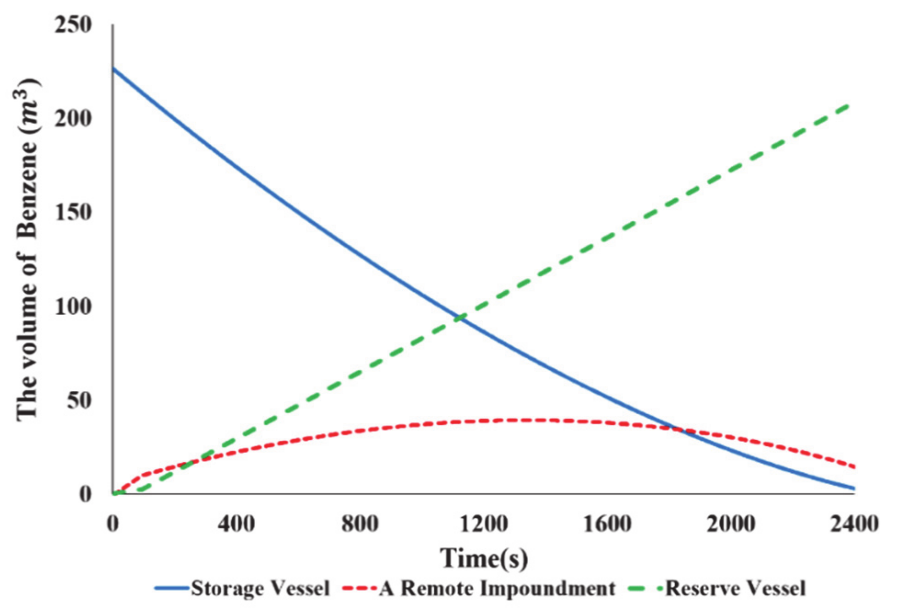
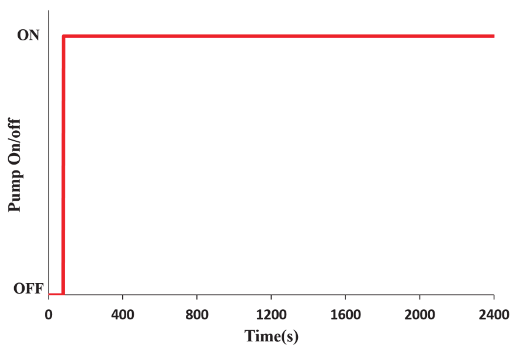
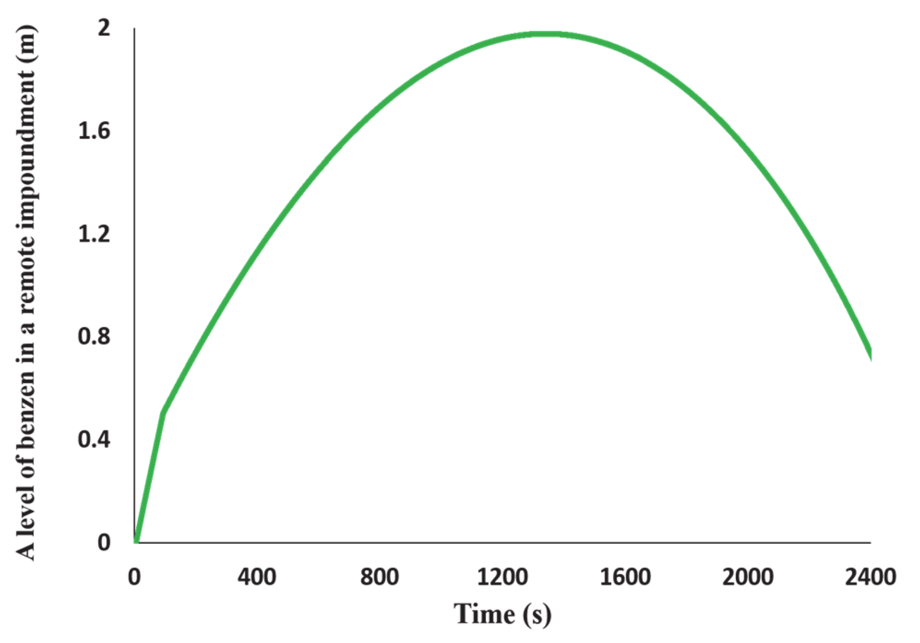
Figure 6,
Figure 7 and
Figure 8 show the results of the benzene leakage when the diameter of the leak hole is 4 inch and its height is 0 m.
Figure 6 shows the level of benzene in the remote impoundment in the case when the capacity of Pump 2 is 238 m
3/h. With this capacity, it is certain that a fluid can be transported as quickly as possible while preventing the overflow of the remote impoundment.
Figure 7 indicates that this system does not suffer from the switching on and off of Pump 2.
Figure 8 shows the level of benzene in the remote impoundment. These case studies show that optimal design specifications including a pump capacity can be determined by considering the conditions of the vessels.
4. Consequence Analysis
The Emergency Response Planning Guidelines (ERPGs) specified by the American Industrial Hygiene Association are the most well-known guidelines for emergency response and planning [
13].
In the ERPGs, three concentration ranges (ERPG-1, ERPG-2 and ERPG-3) for each chemical material are defined and these corresponding three ranges are associated with light, medium and heavy risks, respectively. Among them, ERPG-2 is the most important standard for emergency response and planning, since concentrations above ERPG-2 can cause people to suffer from serious and irreversible health effects The detailed descriptions for the ERPGs are as follows;
ERPG-1: This is the maximum airborne concentration below which it is believed nearly all individuals could be exposed for up to 1 h without experiencing more than mild, transient adverse health effects or without perceiving a clearly defined objectionable odor [
13].
ERPG-2: This is the maximum airborne concentration below which it is believed nearly all individuals could be exposed for up to 1 h without experiencing or developing irreversible or other serious health effects or symptoms that could impair an individual’s ability to take protective action [
13].
ERPG-3: This is the maximum airborne concentration below which it is believed nearly all individuals could be exposed for up to 1 h without experiencing or developing life-threatening health effects [
13].
In this study, the ALOHA (Areal Locations of Hazardous Atmospheres) software developed by the EPA (Environmental Protection Agency) and NOAA (National Oceanic and Atmospheric Administration) is employed to perform the consequence analysis.
Figure 8 shows the results of ERPG-2 with and without a proposed mitigation system when the leak in the HF vessel occurs. The simulation conditions for ALOHA are listed in
Table 2. On the basis of the maximum distance for ERPG-2, the reduction effect of a proposed mitigation system is 0.6%, shown in
Figure 9. This reduction effect is insignificant even though a proposed mitigation system can reduce the amount of material leaked outside by 19.6%. The main reason for this is that the dispersion of liquids is mainly determined by the cross sectional area of a dike. Furthermore, in ALOHA the exposure duration of a leakage material for the puddle source cannot be changed, i.e., the duration is constant. Even if there is no significant change in ERPG-2, the proposed mitigation system can contribute to reducing a large amount of material leaked to the outside. To obtain accurate results for the dispersion, more precise models should be employed.
5. Conclusions
Although a few worksites have installed this type of mitigation system, there has been no scientific method to evaluate the mitigation impact. The main aim of this study is to design a new mitigation system including a reserve vessel and a remote impoundment. To understand the impact of a mitigation system, the proposed mitigation system based on the remote impoundment is designed and evaluated based on mathematical modeling and consequence analysis. When a leak occurs, the material in a storage vessel is transported by a pump and the material in the dike flows into a remote impoundment installed under the ground. The optimal pump capacity should be determined to avoid the repetitive pause of a pump and to guarantee the reliability as preventing the overflow of the remote impoundment.
Through case studies, it is confirmed that the proposed mitigation system can handle materials safely and has a large impact on the reducing the impact of an initial accident. When designing this type of mitigation system for a vessel, this study can also provide scientific approaches and guidelines to determine the proper design specifications and help to reduce cost, efforts, and time for performing the set of experiments.
Author Contributions
H.O.S. wrote the manuscript. J.J. investigated previous researches and validated methodologies and results. C.J.L. wrote the manuscript, supervised and supported this study and critically revised the manuscript. All authors have read and agreed to the published version of the manuscript.
Funding
This research was supported by Basic Science Research Program through the National Research Foundation of Korea (NRF) funded by the Ministry of Education (NRF-2020R1F1A1055442).
Institutional Review Board Statement
Not applicable.
Informed Consent Statement
Not applicable.
Data Availability Statement
Data sharing not applicable.
Conflicts of Interest
The authors declare no conflict of interest.
Nomenclature
| the liquid velocity at the top of a fluid |
| the liquid velocity at a leak hole |
| the height of liquid from the ground |
| the height of a leak hole from the ground |
| the pressure at the top of a fluid |
| the atmosphere pressure around a leak hole |
| the liquid density |
| the gravitational acceleration |
| the moles of an inert gas |
| the gas constant |
| the parameter of Van der Waals equation representing intermolecular attractions |
| the parameter of Van der Waals equation representing excluded volume |
| the radius of a leak hole |
| the cross-sectional area of a storage vessel |
| the cross-sectional area of a remote impoundment |
| the unit step function |
| a time delay between a storage vessel and a remote impoundment |
| the pump capacity for Pump 1 |
| the pump capacity for Pump 2 |
References
- Lee, K.H.; Kwon, H.M.; Cho, S.S.; Kim, J.Y.; Moon, I. Improvements of safety management system in Korean chemical industry after a large chemical accident. J. Loss Prev. Process Ind. 2016, 42, 6–13. [Google Scholar] [CrossRef]
- Meysami, H.; Ebadi, T.; Zohdirad, H.; Minepur, M. Worst-case identification of gas dispersion for gas detector mapping using dispersion modeling. J. Loss Prev. Process Ind. 2013, 26, 1407–1414. [Google Scholar] [CrossRef]
- Sadee, C.; Samuels, D.E.; O’Brien, T.P. The characteristics of the explosion of cyclohexane at the Nypro (UK) Flixborough plant on 1st June 1974. J. Occup. Accid. 1977, 1, 203–235. [Google Scholar] [CrossRef]
- Qiblawi, T.; Balkiz, G.; Paget, S.; Dewan, A.; Regan, H. Emotional Rollercoaster in Beirut as Rescuers End Search for Possible Blast Survivor. Available online: https://edition.cnn.com/2020/09/06/middleeast/beirut-rubble-no-survivors-intl-hnk/index.html (accessed on 7 September 2020).
- Rana, M.A.; Guo, Y.; Mannan, M.S. Use of water spray curtain to disperse LNG vapor clouds. J. Loss Prev. Process Ind. 2010, 23, 77–88. [Google Scholar] [CrossRef]
- Suardin, J.A.; Qi, R.; Cormier, B.R.; Rana, M.; Zhang, Y. Application of fire suppression materials on suppression of LNG pool fires. J. Loss Prev. Process Ind. 2011, 24, 63–75. [Google Scholar] [CrossRef]
- Lim, H.; Um, K.; Jung, S. A study on effective mitigation system for accidental toxic gas releases. J. Loss Prev. Process Ind. 2017, 49, 636–644. [Google Scholar] [CrossRef]
- Prashanth, I.; Fernandez, G.J.; Sunder, R.G.; Boardman, B.J. Factors influencing safety barrier performance for onshore gas drilling operations. J. Loss Prev. Process Ind. 2017, 49, 291–298. [Google Scholar] [CrossRef]
- Busini, V.; Rota, R.J. Influence of the shape of mitigation barriers on heavy gas dispersion. J. Loss Prev. Process Ind. 2014, 29, 13–21. [Google Scholar] [CrossRef]
- Liu, D.; Wei, J. Modelling and simulation of continuous dense gas leakage for emergency response application. J. Loss Prev. Process Ind. 2017, 48, 14–20. [Google Scholar] [CrossRef]
- Lee, K.O.; Park, J.Y.; Lee, C.J. Evaluation of a mitigation system for leakage accidents using mathematical modeling. Korean J. Chem. Eng. 2017, 49, 291–298. [Google Scholar] [CrossRef]
- Flammable and Combustible Liquids Code; NFPA30; National Fire Protection Association: Quincy, MA, USA, 2012; pp. 297–340.
- Emergency Response Planning Guidelines and Workplace Environmental Exposure Levels Handbook; AIHA Press: Falls Church, VA, USA, 2007; pp. 1–68.
| Publisher’s Note: MDPI stays neutral with regard to jurisdictional claims in published maps and institutional affiliations. |
© 2021 by the authors. Licensee MDPI, Basel, Switzerland. This article is an open access article distributed under the terms and conditions of the Creative Commons Attribution (CC BY) license (http://creativecommons.org/licenses/by/4.0/).


