Article

Effects of Processing Parameters for Vacuum-Bagging-Only Method on Shape Conformation of Laminated Composites

1
Department of Mechanical Engineering, Universiti Teknologi PETRONAS, Seri Iskandar 32610, Perak Darul Ridzuan, Malaysia
2
Institute of Health and Analytics (IHA), Universiti Teknologi PETRONAS, Seri Iskandar 32610, Perak Darul Ridzuan, Malaysia
3
Department of Aerospace Engineering, Universiti Putra Malaysia, UPM Serdang 43400, Selangor Darul Ehsan, Malaysia
*
Author to whom correspondence should be addressed.
Processes 2020, 8(9), 1147; https://doi.org/10.3390/pr8091147
Submission received: 3 August 2020 / Revised: 14 August 2020 / Accepted: 18 August 2020 / Published: 14 September 2020
(This article belongs to the Section Materials Processes)

Abstract

:
Complex composite structures manufactured using a low-pressure vacuum bag-only (VBO) method are more susceptible to defects than flat laminates because of the presence of complex compaction conditions at corners. This study investigates the contribution of multivariate processing parameters such as bagging techniques, curing profiles, and laminate structures on laminates’ shape conformation. Nine sets of laminates were produced with a concave corner and another nine sets with a convex corner, both with a 45° inclined structure. Three-way analysis of variance (ANOVA) was performed to quantify thickness variation and spring effect of laminated composites. The analysis for concave and convex corners showed that the bagging techniques is the main factor in controlling the laminate thickness for complex shape applications. The modified (single) vacuum-bag-only (MSVB) technique appeared to be superior when compared to other bagging techniques, exhibiting the least coefficients of variation of 0.015 and 0.016 in composites with concave and convex corners, respectively. Curing profiles and their interaction with bagging techniques showed no statistical significance in the contribution toward laminate thickness variation. The spring effect of laminated composites was investigated by calculating the coefficient of determination (R2) relative to that of the mold. The specimens exhibited a good agreement with R2 values ranging from 0.9824 to 0.9946, with no major data offset. This study provides guidelines to reduce thickness variations and spring effect in laminated composites with complex shapes by the optimum selection of processing parameters for prepreg processing.

1. Introduction

Currently, there is a paradigm shift in the lightweight structural application such as aerospace [1], automobile [2,3], maritime [4] and construction industries [5,6], where the use of traditional metallic structures are being substituted by advanced composites structures. The use of fiber-reinforced composites (FRC) is proliferating due to their preeminent specific mechanical properties [7,8,9,10], design flexibility [11], and fatigue life enhancement [12]. Additionally, the demand for FRC in these industries, especially aircraft and maritime, is growing expeditiously with anticipated demands to increase extensively in the next decade. However, composite manufacturing processes are relatively time-consuming and costly. It poses challenges to meet the rising composite demands which certainly requires innovative and robust production techniques.
Composites for industrial/mass production applications are typically produced by autoclave process under elevated temperature and pressure [13]. In this method, fully saturated prepreg plies with resin are placed on a tool/mold, the setup is enveloped inside a plastic bag. This setup is vacuumed using a vacuum pump and it is then placed inside a pressurized autoclave vessel. The application of elevated pressure and temperature in autoclave processing safeguards nominal void content and first-rate shape conformation [14,15]. However, major drawbacks of the autoclave manufacturing process include the high costs associated with equipment procurement, maintenance and operation, costly nitrogen gas required for pressurizing autoclave vessel, and lengthy cure cycles [16,17,18]. The capacity of autoclaves limits the size and design of parts, and the production rate is primarily affected by autoclave availability [19,20]. The industries are seeking more economical and robust out-of-autoclave (OOA) composite manufacturing techniques as it will be very challenging to meet the growing demand. OOA prepreg processing plays a crucial role to substitute the metallic structures with a lighter and stronger composite structure to meet the needed production rates. Shifting from autoclave to OOA process will allow a more economical, less time-consuming manufacturing process with increased part size flexibility. The autoclave process uses a high pressure to minimize manufacturing-induced defects, while OOA methods only involve a pressure differential of 1 atm maximum, which makes it vulnerable to certain manufacturing-induced defects. Thus, a sound scientific understanding of low-pressure processing methods is required for successful implementation. Several researchers have addressed the issue of low-pressure application in OOA by proposing alternative methods to generate sufficient consolidation pressure. Some of the noteworthy techniques are the use of high-power permanent magnets [21,22] and hot press molds [23]. Among these techniques, magnet assisted composite manufacturing (MACM) is an impressive option with less costs associated with acquisition, tooling and maintenance when compared to hot press molding. However, the major drawback of MACM is that the compression pressure degrades exponentially with the increase in layup thickness which makes this process vulnerable to thicker laminates [22].
Conventionally, a two-step ramp and dwell temperature and pressure profiles, usually referred to as manufacturer’s recommended cure cycle (MRCC), are recommended by the prepreg suppliers. The low-temperature dwell of a typical cure cycle, also known as B-stage or TB, permits the depletion of volatiles and impregnation of resin into dry tows, whereas, the high-temperature dwell, also referred to as C-stage or TC, allows the resin cross-linking and consolidation into a solid final product [24]. The mechanical properties for commercially available prepregs could be further improved by taking induced residual stress/strain into consideration during curing [25,26,27]. Takagaki et al. [26] conducted an in situ residual stress/strain investigation using MRCC and proposed two new cure cycles which ultimately reduced residual strain by 12–18% while tensile strength improved up to 26%. Extended manufacturer’s recommended cure cycle (EMRCC) consists of an extra temperature dwell TB2 after the first TB. The drawback of EMRCC is it requires a relatively longer curing time compared to that of MRCC. Direct cure cycle (DC), on the other hand, raised TB closer to TC. Samples produced using DC are reported to suffer from reduced tensile strength, despite an 18% improved residual strain when compared to those of MRCC. The modified cycles showed no significant changes in the void content. To date, the information on the effects of various bagging techniques for composites with complex shapes produced using these cure cycles are not readily available.
Among bagging techniques, most conventionally used is a typical one bag setup which creates one vacuum environment, hereby referred to as single vacuum-bag-only (SVB) in this study. This technique is readily used for composites with flat or streamline structures [27]. However, SVB is vulnerable to thickness deviation in composite structures with blunt corners [28]. A modified single vacuum-bag-only (MVSB), also uses one bag to create a vacuum environment but it incorporates the use of metallic or polymeric intensifiers, caul-sheets or pressure strips in the corners of complex structures [29,30,31]. The bridging effect in complex shape structures, where laminates do not completely conform to the shape of the mold, is prevented by the use of an MSVB technique. Double vacuum-bag-only (DVB) uses two vacuum environments by using either a rigid chamber [32] or two bags (inner and outer bags), which are separated by an intermediate metallic perforated tool [33] to facilitate volatile depletion during B-stage. During low-temperature dwell, there is a pressure difference maintained between both bags to create a ballooning effect, i.e., 100 kPa for the outer bag and 95 kPa for inner bag. In this case, a pressure application of 100 kPa (which is the maximum pressure) is considered full vacuum, while pressure below 100 kPa is considered partial vacuum. DVB uses a partial pressure of 95 kPa in the inner environment while a full 100 kPa pressure in the outer environment during B-stage to create a ballooning effect inside the inner environment which consequently allows trapped volatiles to escape, also known as degassing phase. Whereas, the outer bag is purged to the atmosphere and a full vacuum is drawn in the inner environment for final consolidation, also referred to as the compaction phase [32,33]. Unfortunately, the literature related to the adaptability, efficiency, and performance of the DVB technique to commercial and industrial applications is not readily available. Furthermore, their effects on the use of various curing profiles for composites with complex shapes are also not reported.
There are several challenges in producing laminated composites with complex shapes. The most frequent concern is the thickness deviation of corner regions from that of the flange regions in complex-shaped laminates [29,34]. The highest thickness gradients, either corner thickening or thinning, are said to be dependent upon the ply orientation and the curvature of the molds [35]. Manufacturing-induced defects can get worse with the increase in the part sizes and geometric complexity. Thickness variation refers to the thickness difference between corner region and nominal flange region thicknesses. Thickness uniformity in corner regions and flange regions is an accepted quality characteristic for laminates with complex shapes because it is easy to quantity [36,37]. The main reason behind thickness variations in composites with complex structures is the difference in reaction pressure acting at the corner and the flange regions [36]. Experimental verification was performed by using a pressure sensor at the corner region for a 10 mm thick laminate compacted on a 12 mm radius female mold, in which a significant 40% compaction pressure drop was observed in the corner region, as shown in Figure 1. Furthermore, inter-ply friction prevented conducive shape conformation, which leads to corner thickness variation [34,38]. However, the information on the effects of various bagging techniques using different curing profiles and laminate spring effect after releasing from the mold are not reported.
The studies showed that residual stresses are inevitably built up mainly due to different thermal expansion coefficients between matrix and fibers during prepreg processing [39]. An increase or decrease in the enclosed angles of the angled section is referred to as spring effect [40]; either spring back or spring forward. Spring back is defined as a positive angular difference due to the widening of the angle between the formed composite laminate and the mold geometry while spring forward is described as a negative angular difference. The spring effect in the final product creates problems in the final assembly due to poor fit with the mating structures, which is usually dealt with some compensation factors during designing. Certain characteristics of the materials, such as anisotropic mechanical behavior during the curing process is also a reason for the spring effect [41]. Several parameters are suspected to have an influence on the spring effect, which are characterized as intrinsic or extrinsic parameters. Intrinsic parameters are the physical characteristics of the laminated composites, whereas extrinsic parameters are related to manufacturing process parameters and tooling [42]. The spring effect of composite laminates due to the rise of residual stresses and distortions is also influenced by the tool-part interaction. Metallic molds expand more than the laminates during curing, causing laminate tension [43]. To avoid assembly problems, spring effect in composite parts must be fully understood and controlled through optimization.
In this paper, the aim is to investigate the thickness variation and spring effect of 45° angled composite laminates using various bagging techniques (SVB, MSVB and DVB), curing profiles (MRCC, EMRCC and DC) and composite structures (concave and convex corners). The goal is to examine and understand the effect of these processing parameters on the shape conformation i.e., corner thickness variation and spring effect, on the laminated composites with complex shapes.

2. Materials and Methods

2.1. Materials

Out-of-autoclave carbon prepregs XC110 3 K, 210 g, 2/2 Twill with 58% fiber content by weight impregnated with 42% epoxy resin bisphenol-A-(epichlorohydrin) on both sides were used to manufacture laminated composite samples. Prepregs stacking sequence of [0°]n for all samples were used; where n is the number of the prepreg plies used i.e., ten plies with a 0.25 mm each nominal thickness in this study. The consumables for vacuum bag (VB) assembly comprise of polyester woven breather cloth, nylon bagging film, polyolefins perforated release film, and sealant tape. Memmert Model 400 heating oven was used to cure composite laminates at elevated temperatures.

2.2. Design of the Mold and Intensifier

A mold was manufactured from a single block of aluminum using computer numerical control (CNC) machining with a tolerance of ± 0.5 mm, as shown in Figure 2. The mold has a convex and a concave corner at 45° each with a corner radius of 6.35 mm. All corners were rounded to a radius of 2 mm, to avoid rupturing of the bag under vacuum. All flat and inclined flanges of the mold have dimensions of 65 mm × 100 mm. This mold was used in the manufacturing of all sets of specimens for various bagging techniques and curing profiles. An intensifier of dimensions 65 mm × 100 mm with a 45° convex corner was manufactured to perfectly fit on the concave side of the mold using wire cut. All corners of the intensifier were rounded to a radius of 2 mm, to avoid rupturing of the bag under vacuum. The corner radius between the flat and inclined flanges of the intensifier was 6.35 mm. For the convex corner, a 3 mm thick stainless steel bent at 45° with a corner radius of 6.35 mm was used. These intensifiers were used to manufacture composite laminates using MSVB techniques with various curing profiles.

2.3. Design of Perforated Tool

A perforated tool was used to manufacture composite laminates using the DVB technique with various curing profiles. A 2 mm perforated steel sheet with 15 mm diameter holes distant at 25 mm apart was bent to use as a separator tool to manufacture laminated composites using the DVB technique. The dimensions of the perforated tool are 430 mm × 280 mm × 130 mm. A small window of 80 mm × 50 mm was cut on both longitudinal sides of the tool to facilitate easy inspection of the inner bag. All edges of the tool were grinded properly using a disk grinder; the high-temperature tape was applied on all corners and window boundaries to avoid rupturing of the bag due to sharp burs under vacuum. Additionally, three reinforcements of 20 mm × 20 mm × 2 mm (mild steel) square hollow section were employed to avoid inward bending of tool’s walls under vacuum.

2.4. Taguchi Orthogonal Array

Taguchi orthogonal arrays are highly fractional designs, used to estimate main effects using only a few experimental runs. Taguchi full fractional trail requires a total of 3k runs for k number of factors to be studied. In such an experimental design, k runs are used to study the “effects” of factors, while the remaining runs are used to track all possible interactions between these factors. When an investigation of every possible interaction becomes time-consuming and expensive, a Taguchi fractional factorial trial could be used to analyze only the “main effects” which give sufficient information from only a few experimental trials. The main effects refer to the contributing factors themselves as an individual. themselves as an, not effects due to interactions between the factors. Nine sets of laminate samples were produced using bagging techniques (SVB, MSVB, and DVB), curing profiles (MRCC, EMRCC, and DC) and laminate shapes (concave and convex). Each set of experiments is repeated three times to ensure the repeatability. Taguchi L9 orthogonal array was used for both concave- and convex-cornered composite laminates, as shown in Table 1.

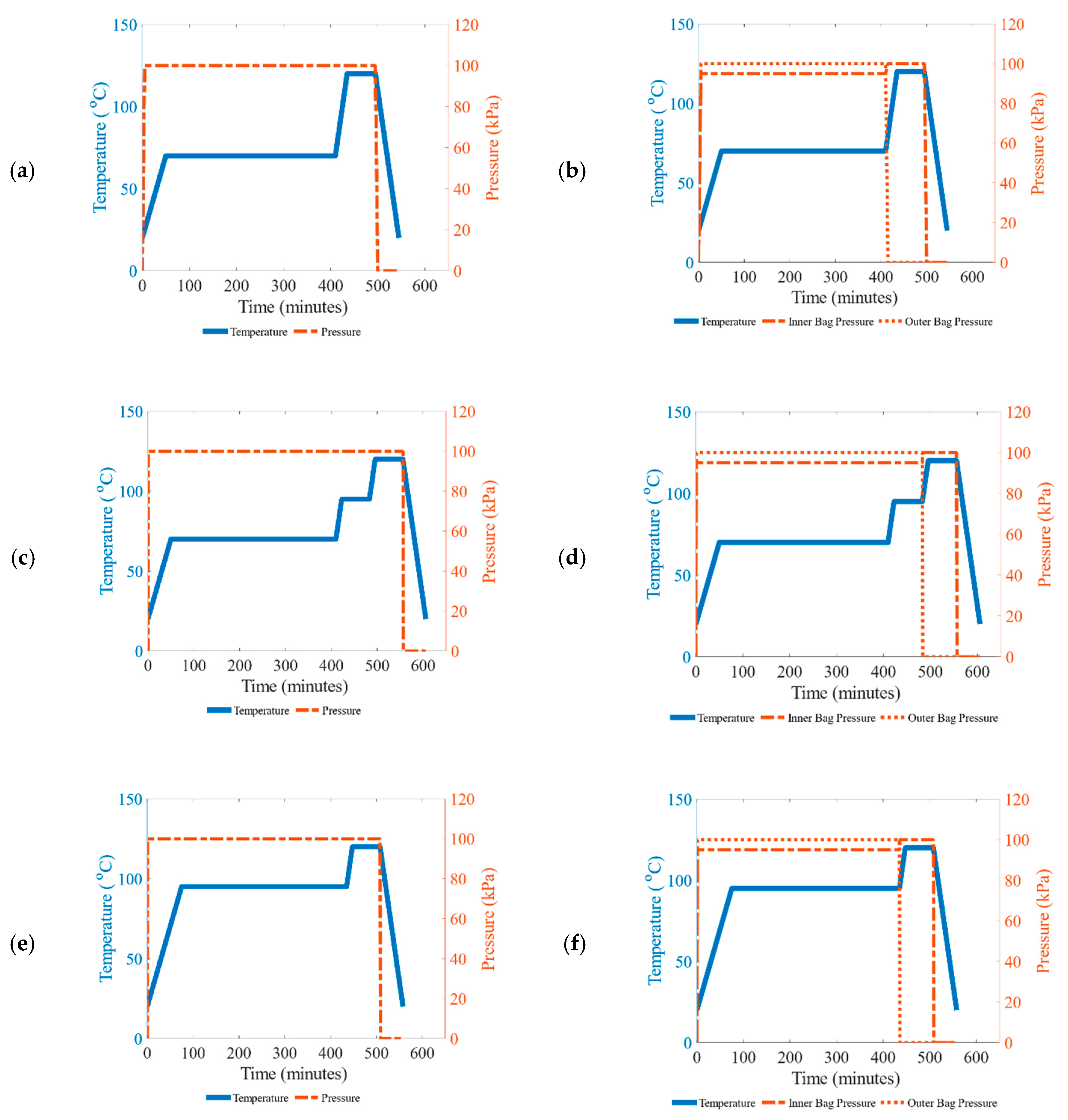
2.5. Curing Profiles

Carbon prepregs of dimensions 100 mm × 50 mm were given an adequate four days of freezer out-time at 20 °C before processing. The stacking of prepregs onto the mold was performed without debulking. An MRCC for SVB and MSVB technique consists of 4 h dwell at 70 °C (B-stage) and 1 h dwell at 120 °C (C-stage), as shown in Figure 3a. Two ramp rates were used: 1 °C/min up to 70 °C, and 2 °C/min from 70 °C to 120 °C. A full vacuum was pulled at room temperature by applying 100 kPa pressure until the end of C-stage. The temperature profile in the MRCC for DVB is similar to that for SVB. Unlike SVB and MSVB, DVB consists of two pressure profiles due to the presence of two vacuum bags, as shown in Figure 3b. The pressure inside the inner bag is 95 kPa (partial vacuum) during B-stage and 100 kPa pressure (full vacuum) during C-stage. A full vacuum was drawn inside the outer bag during B-stage (to create a ballooning effect in the inner bag) while it was purged to the atmosphere during C-stage.
EMRCC profile was determined by differential scanning calorimetry (DSC) Q2000 V24. The glass transition temperature (Tg) was determined to indicate a low degree of cure for uncured resin. Hence, EMRCC for SVB and DVB techniques was formulated by incorporating an additional one hour dwell at 95 °C with a ramp rate of 2 °C/min. EMRCC for SVB and MSVB techniques are shown in Figure 3c with a single pressure profile (for a single bag). Figure 3d indicates two pressure profiles for inner and outer bags used in DVB, whereas the temperature profile is identical in both SVB/MSVB and DVB techniques. For DC, the first dwell temperature was set to 95 °C instead of the recommended 70 °C (as in MRCC) for 6 h for both SVB and DVB. DC for SVB and MSVB techniques are shown in Figure 3e with a single pressure profile (for a single bag) and Figure 3f indicates two pressure profiles for inner and outer bags used in DVB, whereas the temperature profile is identical in both SVB/MSVB and DVB techniques.

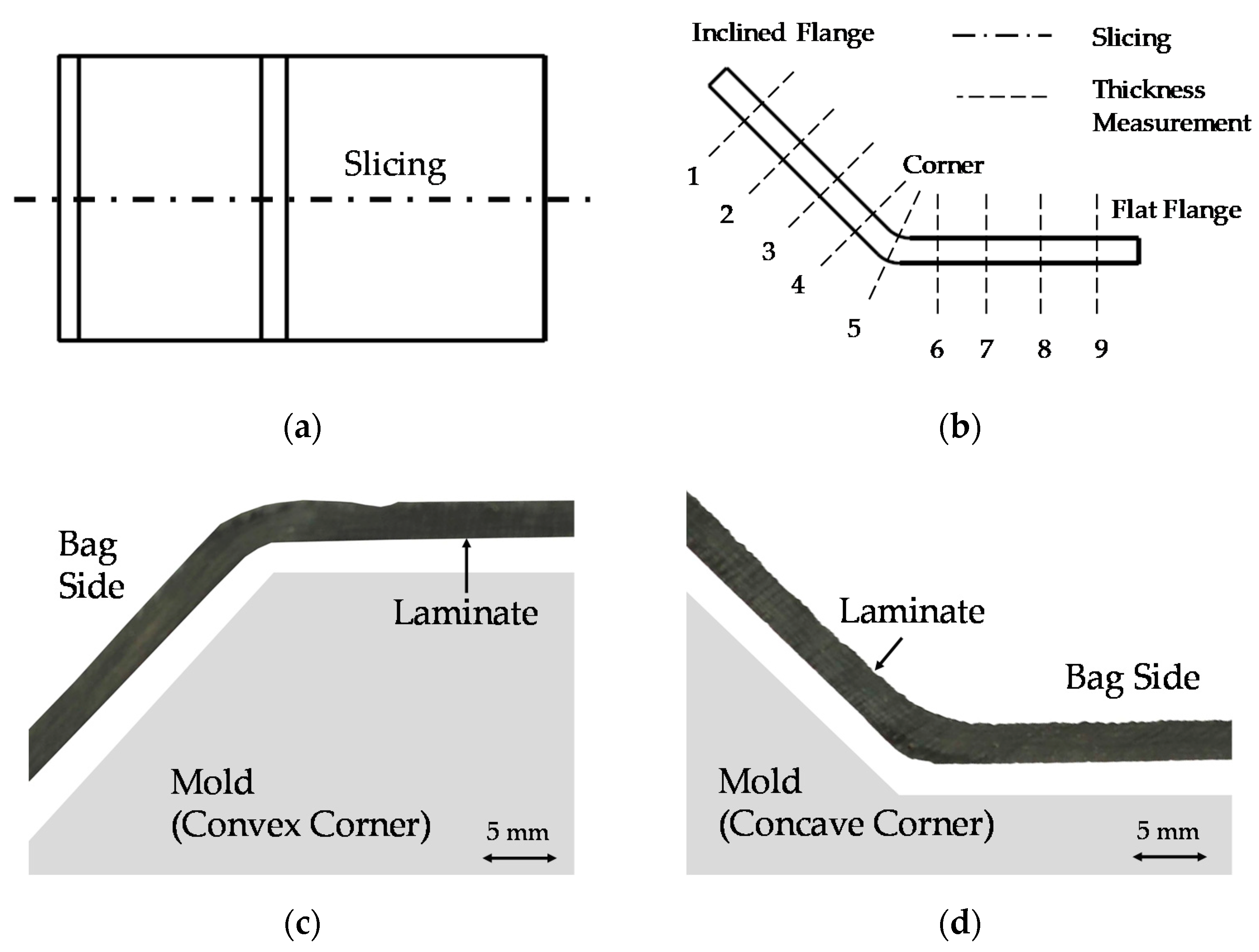
2.6. Characterization of Thickness Variation and Spring Effect

All samples were cut from the center into two equal pieces using a C350 diamond blade cutter with a 350 mm diameter. Inward-facing cross-sectional areas of all samples were then polished by 500, 800, and 1000 grit sandpapers, respectively. To quantify the laminate thickness, nine measurement locations were selected, with three located in the left flange, three in the corner, and three in the right flange, as shown in Figure 4. The thickness at each individual location was then measured using a Mitutoyo 0–25 mm micrometer screw gauge with a precision up to 0.001 mm. For each location, an average of six readings were calculated. The coefficient of variation (CoV) of the thickness, shown in Equation (1), was used to compute a single numerical metric for the thickness non-uniformity of the entire laminate (n is the number of measurement locations). Once the samples completed their curing cycles in the oven, the mold was allowed to cool down for 20 min. The samples were removed from the mold and then they were allowed to spring back or spring forward. The angle of deformation was measured for every specimen. The coefficient of determination (R2) was calculated to quantify the spring effect, which is a statistical measure of how close the specimens were to the actual mold shape.
Coefficient   of   Variation = 1 x ¯ Σ ( x x ¯ ) 2 n 1

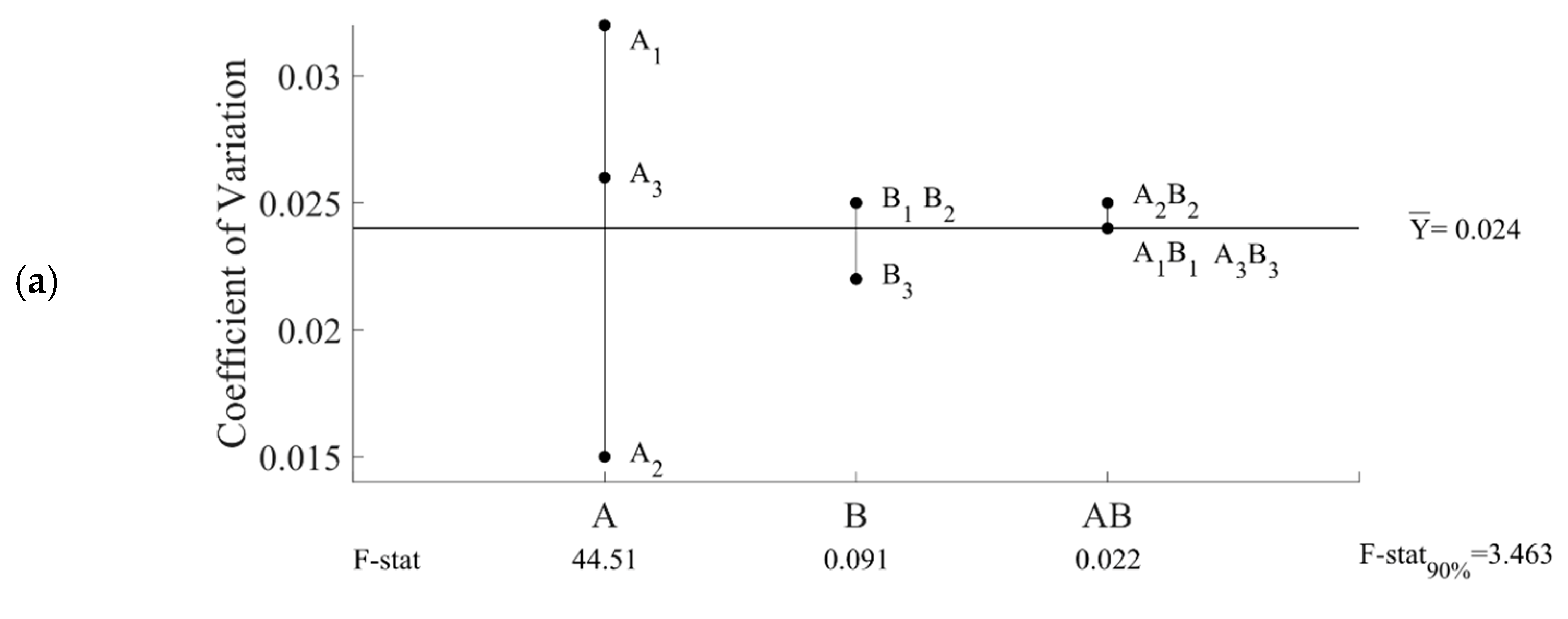
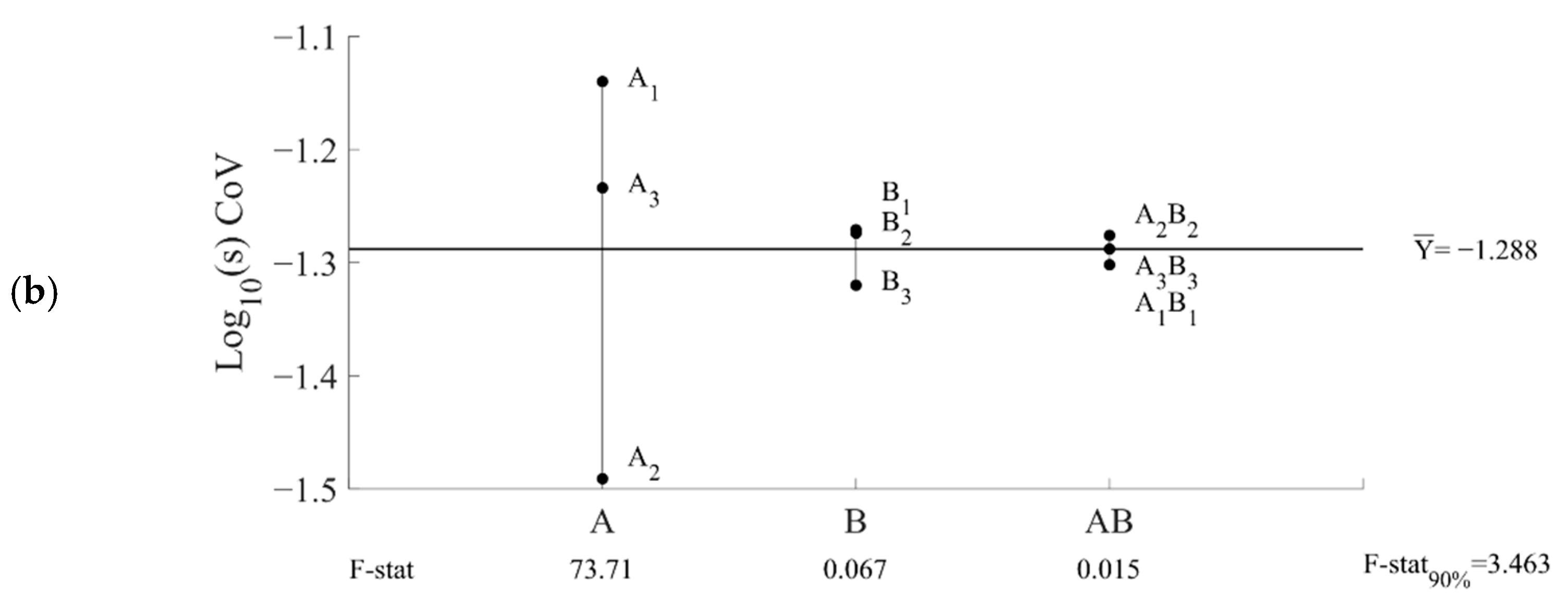
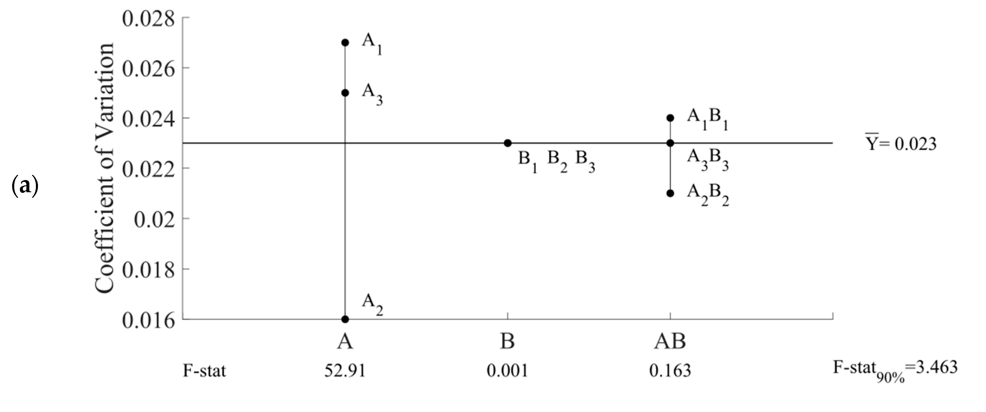
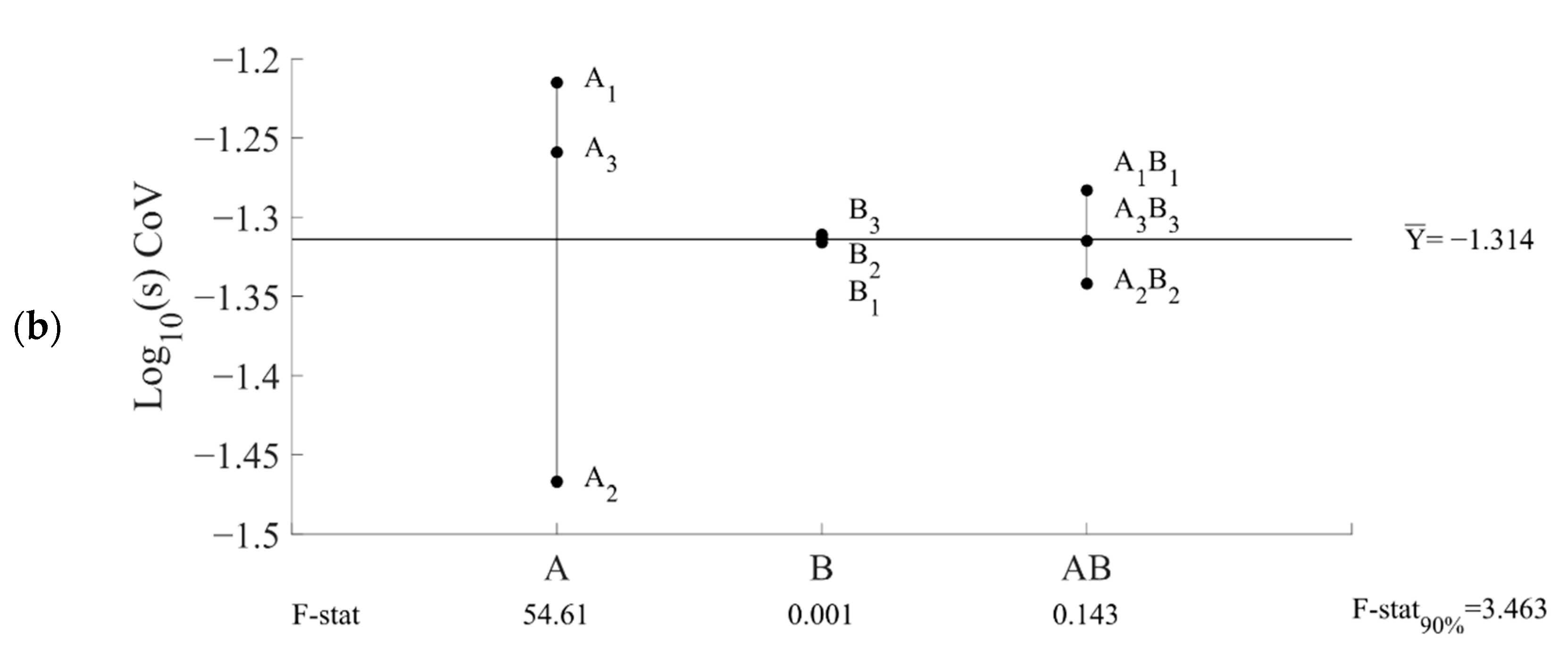
2.7. Analysis of Variance (ANOVA)

Three-way analysis of variance ANOVA was used to determine the significance and percentage contribution of each individual parameter and their interaction between each other based on a 90% confidence level. The variability of thickness variation and spring effect results is represented by Log10 of the standard deviations. Logarithms are taken in the case of standard deviations; when randomly distributed, such data will adequately fit a normal distribution, whereas untransformed standard deviation data do not [44].

3. Results and Discussion

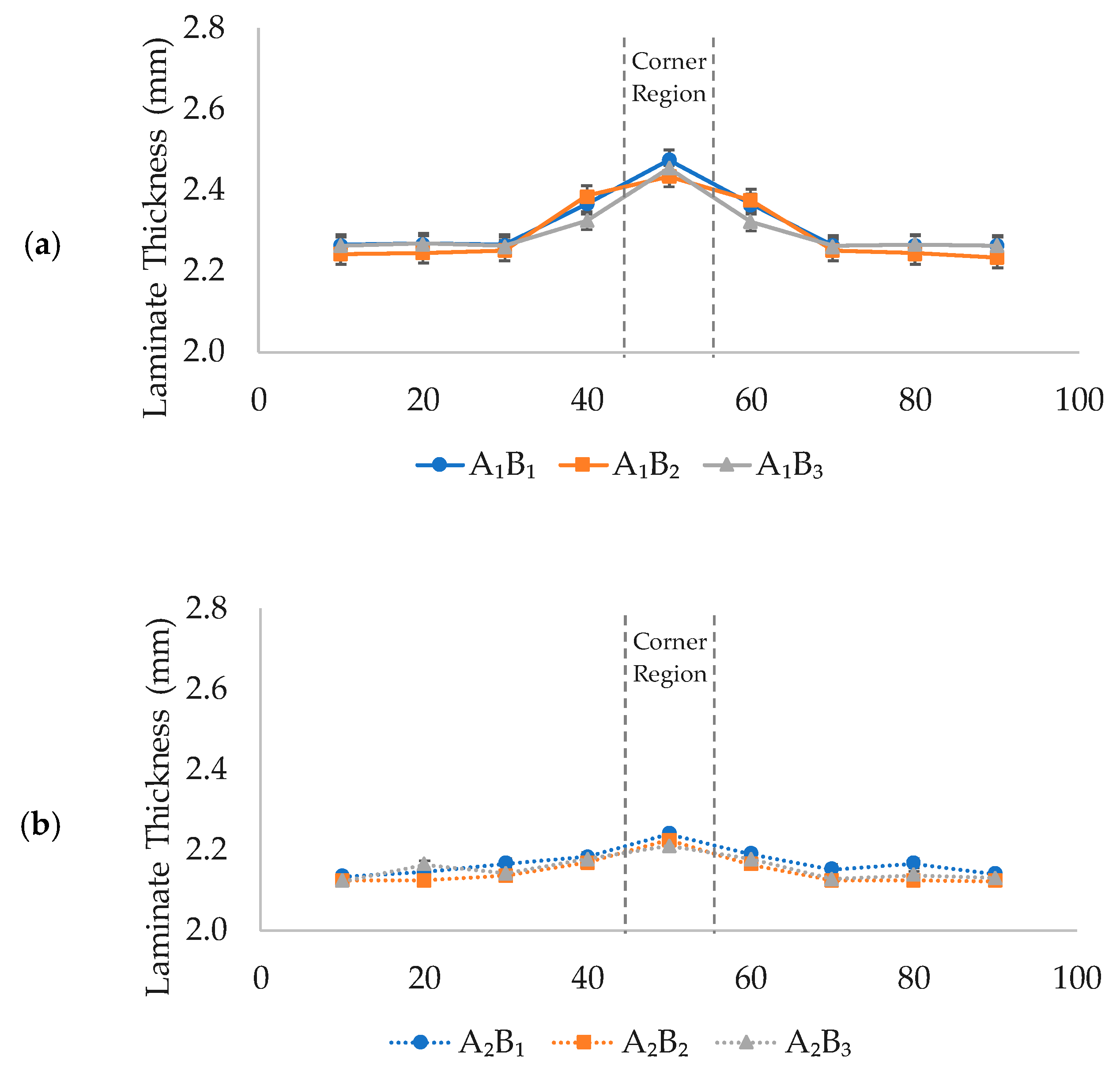
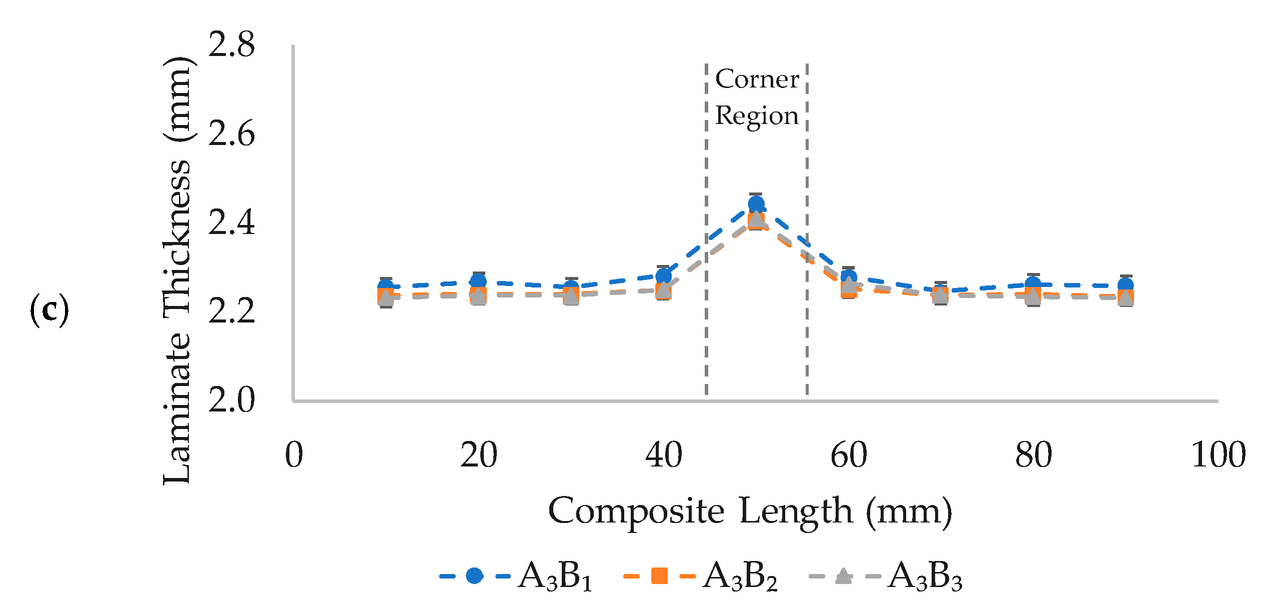
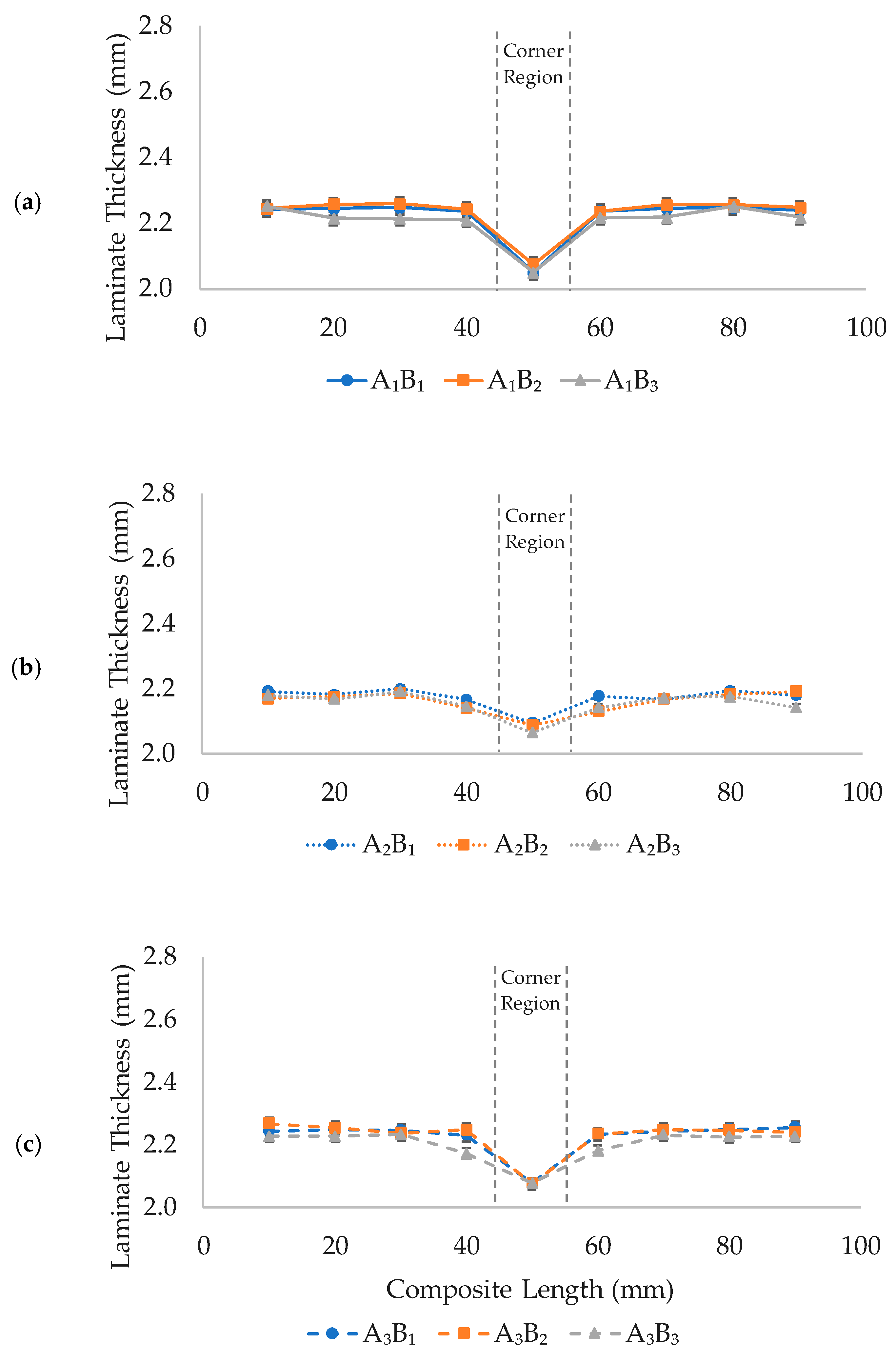
3.1. Thickness Variation of Laminated Composites

In terms of thickness variation, the lesser CoV is desirable as it illustrates a lower variation in the thickness across the entire laminated composite. The lesser variation in the laminate thickness ensures uniformity in the composite structure. The results for CoV in the laminate thickness produced on the concave corner of the mold and their variability are shown in Figure 5a,b respectively. The grand means ( Y ¯ ) are mentioned in the center right, F-stat shows the calculated F-statistic values while F-stat90% illustrates the critical F-statistic value at 90% confidence. The grand means of the CoV and variability for concave-cornered laminates are 0.024 and −1.288, respectively. Within the scope of this study, vacuum bagging technique is the only parameter to demonstrate a statistically significant effect on the laminate thickness with an F-stat of 44.51(>F90%). SVB was chosen as a base technique to compare with others since it is a conventional method. SVB exhibited the highest variation in thickness, followed by DVB, while MSVB exhibited the lowest thickness variation. The highest CoV of 0.032 (3.2% deviation) in the SVB is attributed to the bridging effect, in which the laminate does not conform to the mold shape completely, hence the thickness in the concave corner is higher than the rest of the laminates. It is difficult for the complex-shaped laminate (concave in this case) to conform to the shape of laminate with only 1 atm pressure. Although the corner radius is provided in the mold to prevent major corner deviation, the decrease in the reaction pressure on the corner regions causes insufficient pressure application on the concave corner regions, as demonstrated by Arthur Levy and Pascal Hubert [34]. The thickness variation in DVB witnessed a 22.84% improvement when compared to those of SVB. Whereas, MSVB technique witnessed a tremendous improvement of 110.81% when compared to those of SVB technique with a CoV of 0.015. The use of intensifiers on the concave corner increases the pressure distribution conditions to prevent bridging. This finding has also been reported in a previous study [29]. The thickness deviations reported in this study for laminates with concave corner produced using MSVB technique are in good agreement with their findings.
Curing cycles and their interaction with bagging techniques were found to be statistically insignificant. This shows that the main factor in controlling the thickness of laminated composites (with concave corners) is attributed to the bagging techniques and consolidation method. The variability in the results of thickness variation in the concave corner illustrates the statistical significance of bagging techniques with an F-stat of 73.71 (>F90%). SVB and DVB techniques exhibited massive variations with standard deviations of 0.073 and 0.058, respectively. The variability in the results is better understood by plotting the average thickness of laminates across the length, as shown in Figure 6. The thickness fluctuates excessively in SVB when compared to those of MSVB and DVB. It is noticed that the variation in the flat flange of the laminate is lower than the inclined flange in all three cases. The highest corner thickening is also observed in SVB and DVB which are averaged at 2.455 mm and 2.420 mm, as shown in Figure 6a,c, respectively. Major corner thickening in these techniques in comparison to the rest of the laminate thickness is offsetting the CoV values. Whereas, MSVB witnesses a significant improvement of 10.34% in corner thickness when compared to SVB with an average corner thickness of 2.225 mm, as shown in Figure 6b. This improvement is due to the application of an intensifier in the corner region. It is also observed that the entire laminate thickness for MSVB is averaged at 2.156 mm, which is 6.76% thinner than the SVB, indicating the effective laminate consolidation.
The results for CoV in the laminate thickness produced on the convex corner of the mold and its variability are presented in Figure 7a,b, respectively. The grand means of the CoV and variability for convex-cornered laminates are 0.023 and −1.314, respectively. Similar to the pattern observed for concave corner results, vacuum bagging technique is the only parameter to demonstrate a statistically significant effect on the laminate thickness. SVB and DVB techniques exhibited a similar variation in thickness with CoV values 0.027 and 0.025, respectively. The high thickness variation in SVB is attributed to the corner thinning effect. MSVB technique is able to avoid a major corner thinning because the use of caul-sheet prevents a higher reaction pressure to consolidate excessively. Hence, excessive and unnecessary corner suppression is avoided. A similar finding is reported by Yijia Ma et al. [26]; the CoV results reported in this study are in good agreement to theirs.
Similar to concave results, curing cycles and their interaction with bagging techniques were found to be statistically insignificant. This also shows that the main factor in controlling the laminate thickness (with convex corners) is attributed to the bagging techniques and consolidation methods. The variability in the results of thickness variation in the convex corner illustrates the statistical significance of bagging techniques with an F-stat of 54.61 (>F90%). A noticeable corner thickness variation was exhibited in SVB and DVB techniques with standard deviations of 0.061 and 0.055, respectively. The average thicknesses across the length of the laminates are plotted to better understand the variability in results, as shown in Figure 8. A major corner thinning is observed in SVB and DVB with an average of 2.058 mm and 2.076 mm, as shown in Figure 8a,c, respectively. The high CoV values achieved in SVB and DVB techniques are attributed to the noticeable corner thinning. Whereas, MSVB technique exhibited 2.082 mm thickness with a standard deviation of 0.034, as shown in Figure 8b. Despite the corner thinning, the laminates produced using SVB and DVB are 2.161% thicker than those produced using MSVB. This shows the effectiveness of the intensifier in controlling the laminate thickness by controlling the uniformity of the compaction force.
An overall analysis of thickness variation showed a good consistency for the MSVB technique to not only maximize the shape conformation by avoiding bridging effect in the concave corner of the mold to prevent major corner thickening but also to prevent major corner thinning in convex corners. This study provides a basis to reduce thickness variations in laminated composites with complex shapes by an optimum selection of processing parameters for prepreg processing. For example, for a given laminate layup and geometry (corner angle), a concave molding set-up may be converted to a convex one to reduce defect levels. The results suggest that using a mold with convex corner angle is better than that of concave corner angles. Where it is necessary to use concave corners, an increase in local curvature angles and corner radii may avoid corner thickening and resin accumulation. Furthermore, the use of intensifiers could further maximize thickness uniformity. Finally, for a typical prepreg processing with various choices of bagging techniques, cure cycles and molding conditions, these results provide invaluable insight for final laminate quality.

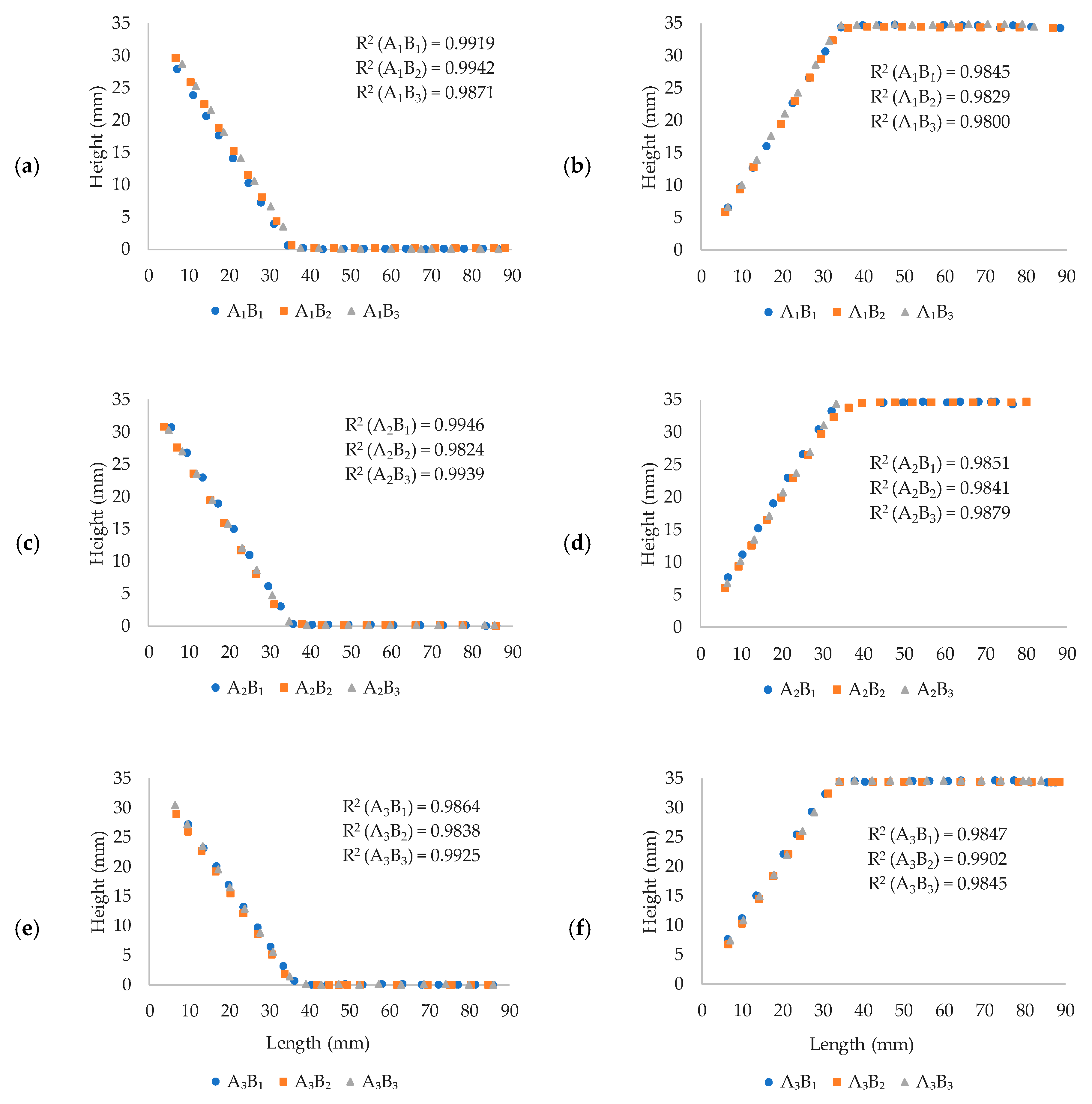
3.2. Spring Effect of Laminated Composites

Consistency for the laminated composite to retain the original shape without any spring-forward or spring-back after curing is highly sought by composite manufacturers. A significantly large amount of residual stresses in laminated composites are likely to develop during the curing process using complex-shaped molds with blunt corners and lack of draft angle. Figure 9 illustrates the traces of manufactured laminates relative to that of the mold. Figure 9a, c and e shows concave-cornered laminates produced using SVB, MSVB and DVB techniques, respectively. Whereas, Figure 9b,d,f illustrates convex cornering using SVB, MSVB, and DVB techniques, respectively. Spring effect is measured by the measuring the corner angle of final consolidated part. Spring-back effect occurs when the edges of the final laminates are shrunk inwards. In this case, the final corner angle tends to reduce compared to that of intended. Whereas, spring-forward effect occurs when the edges of the final laminates are widened outwards. In this case, the final corner angle tends to increase when compared to that of intended. Please note that there was no visible spring-back or spring-forward behavior. The coefficient of determination (R2) was calculated for all concave- and convex-cornered composites relative to that of the mold and the results are plotted in Figure 9. It was found that the samples shape showed a very close agreement with that of the mold. An insignificant variation in the inclined flange for concave-cornered laminated composites is observed, which can be explained by the relaxation of very low residual stresses accumulated at the corners to ultimately cause deviation. Whereas, the flat flange showed a remarkably close agreement in all bagging techniques and curing profiles. Furthermore, convex-cornered laminated composites showed excellent agreement in both inclined and flat flange regions; however, a slight decrease in the coefficient of correlation is subjected to corner thinning effect which causes data offset during observation.
The overall investigation of spring effect (forward and back) in complex shapes showed local curvature angles with adequate corner rounding i.e., 45° with a 6.35 mm radius, decreases the potential for deformation after curing. The results reveal fundamental information associated with complex-shaped laminated composites and provide a basis for developing effective manufacturing guidelines. This research highlights the potential of complications with the increase in part size and complexity such as curvature angle and corner radii. Therefore, the results presented in this work must be combined with further research on other processing parameters affecting the shape conformation of prepreg processing.

4. Conclusions

This study investigates the effects of multivariate processing parameters including vacuum bagging techniques (single vacuum-bag-only, modified single-vacuum-bag-only, and double vacuum-bag-only), curing profiles (manufacturer’s recommended curing cycle, extended manufacturer’s recommended curing cycle, and direct cure cycle) and laminate structures (concave corner and convex corner) on the shape non-conformity of complex-shaped laminated composites. The results showed a good consistency in laminate thickness uniformity for the MSVB technique; it does not only maximize the shape conformation by avoiding bridging effect in the concave corner of the mold to prevent major corner thickening but it also prevents major corner thinning in convex corners. This study provides a basis to reduce thickness variations in laminated composites with complex shapes by an optimum selection of processing parameters for prepreg processing. The results suggest that using a mold with convex corner angle is better than that of concave corner angles. Applications were the use of concave corners is a must condition, an increase in local curvature angles and corner radii of the mold could avoid corner thickness deviation and resin accumulation. Furthermore, the use of intensifiers could further maximize thickness uniformity. Curing profiles and their interaction with bagging techniques showed no statistical significance in the controllability of laminate thickness variation. The coefficient of correlation exhibited a good agreement in terms of spring effect for all samples with no major data offset.
The statistical analysis of VBO processing parameters and their effects on shape non-conformity provide important information for defect controllability in complex-shaped laminated composites. Understanding the consolidation of laminates with complex shapes provide vital insight to design experimental guidelines for corner thickness variation and spring effect for various processing parameters. The results presented in this study could also be extended to other OOA processes with various complicated part geometries, such as those employing inserts during manufacturing.

Author Contributions

Conceptualization, Y.M., N.S.; methodology, Y.M., N.S.; experimentation, Y.M.; investigation, Y.M., N.S.; resources, N.S., M.M.; data curation, Y.M., N.S., M.Z.A., F.M.; writing—original draft preparation, Y.M.; writing—review and editing, Y.M., N.S., M.Z.A., F.M.; supervision, N.S., M.Z.A.; project administration, Y.M., N.S., M.M.; funding acquisition, N.S., M.M. All authors have read and agreed to the published version of the manuscript.

Funding

This research was partially funded by Yayasan Universiti Teknologi PETRONAS under grant number YUTP-FRG-015LC0-247.

Acknowledgments

The authors are thankful to Universiti Teknologi PETRONAS for providing financial assistance and highly sought facilities to conduct this research. Y.M. would like to express great appreciation to Ali Naqi Taqi of Meezan Educational Trust, Pakistan, for invaluable insight and support.

Conflicts of Interest

The authors declare no conflict of interest.

References

  1. Degenhardt, R.; Castro, S.G.; Arbelo, M.A.; Zimmerman, R.; Khakimova, R.; Kling, A. Future structural stability design for composite space and airframe structures. Thin Walled Struct. 2014, 81, 29–38. [Google Scholar] [CrossRef] [Green Version]
  2. Sun, G.; Yu, H.; Wang, Z.; Xiao, Z.; Li, Q. Energy absorption mechanics and design optimization of CFRP/aluminium hybrid structures for transverse loading. Int. J. Mech. Sci. 2019, 150, 767–783. [Google Scholar] [CrossRef]
  3. Elmarakbi, A. Advanced Composite Materials for Automotive Applications: Structural Integrity and Crashworthiness; John Wiley & Sons: West Sussex, UK, 2013. [Google Scholar]
  4. Tran, P.; Nguyen, Q.T.; Lau, K. Fire performance of polymer-based composites for maritime infrastructure. Compos. Part B Eng. 2018, 155, 31–48. [Google Scholar] [CrossRef]
  5. García-Espinel, J.D.; Alvarez-García-Lubén, R.; González-Herrero, J.; Castro-Fresno, D. Design and construction methods of caisson-type maritime infrastructures using GFRP. J. Compos. Constr. 2016, 20, 05015002. [Google Scholar] [CrossRef]
  6. Ribeiro, F.; Sena-Cruz, J.; Branco, F.G.; Júlio, E. Hybrid effect and pseudo-ductile behaviour of unidirectional interlayer hybrid FRP composites for civil engineering applications. Constr. Build. Mater. 2018, 171, 871–890. [Google Scholar] [CrossRef] [Green Version]
  7. Wagih, A.; Sebaey, T.; Yudhanto, A.; Lubineau, G. Post-impact flexural behavior of carbon-aramid/epoxy hybrid composites. Compos. Struct. 2020, 239, 112022. [Google Scholar] [CrossRef]
  8. Zegaoui, A.; Derradji, M.; Dayo, A.Q.; Medjahed, A.; Zhang, H.-Y.; Cai, W.-A.; Liu, W.-B.; Ma, R.-K.; Wang, J. High-performance polymer composites with enhanced mechanical and thermal properties from cyanate ester/benzoxazine resin and short Kevlar/glass hybrid fibers. High Perform. Polym. 2019, 31, 719–732. [Google Scholar] [CrossRef]
  9. Matykiewicz, D. Biochar as an Effective Filler of Carbon Fiber Reinforced Bio-Epoxy Composites. Processes 2020, 8, 724. [Google Scholar] [CrossRef]
  10. Shah, S.; Megat Yusoff, P.S.; Karuppanan, S.; Sajid, Z. Elastic Constants Prediction of 3D Fiber-Reinforced Composites Using Multiscale Homogenization. Processes 2020, 8, 722. [Google Scholar] [CrossRef]
  11. Singh, A.P.; Sharma, M.; Singh, I. A review of modeling and control during drilling of fiber reinforced plastic composites. Compos. Part B Eng. 2013, 47, 118–125. [Google Scholar] [CrossRef]
  12. Wu, T.; Zhang, K.; Cheng, H.; Liu, P.; Song, D.; Li, Y. Analytical modeling for stress distribution around interference fit holes on pinned composite plates under tensile load. Compos. Part B Eng. 2016, 100, 176–185. [Google Scholar] [CrossRef]
  13. Grunenfelder, L.; Dills, A.; Centea, T.; Nutt, S. Effect of prepreg format on defect control in out-of-autoclave processing. Compos. Part A Appl. Sci. Manuf. 2017, 93, 88–99. [Google Scholar] [CrossRef] [Green Version]
  14. Bodaghi, M.; Cristóvão, C.; Gomes, R.; Correia, N. Experimental characterization of voids in high fibre volume fraction composites processed by high injection pressure RTM. Compos. Part A Appl. Sci. Manuf. 2016, 82, 88–99. [Google Scholar] [CrossRef]
  15. Xu, X.; Wang, X.; Liu, W.; Zhang, X.; Li, Z.; Du, S. Microwave curing of carbon fiber/bismaleimide composite laminates: Material characterization and hot pressing pretreatment. Mater. Des. 2016, 97, 316–323. [Google Scholar] [CrossRef]
  16. Thomas, S.; Bongiovanni, C.; Nutt, S. In situ estimation of through-thickness resin flow using ultrasound. Compos. Sci. Technol. 2008, 68, 3093–3098. [Google Scholar] [CrossRef]
  17. Tavares, S.S.; Michaud, V.; Månson, J.-A. Through thickness air permeability of prepregs during cure. Compos. Part A Appl. Sci. Manuf. 2009, 40, 1587–1596. [Google Scholar] [CrossRef]
  18. Tavares, S.S.; Michaud, V.; Månson, J.-A. Assessment of semi-impregnated fabrics in honeycomb sandwich structures. Compos. Part A Appl. Sci. Manuf. 2010, 41, 8–15. [Google Scholar] [CrossRef]
  19. Centea, T.; Grunenfelder, L.K.; Nutt, S.R. A review of out-of-autoclave prepregs–Material properties, process phenomena, and manufacturing considerations. Compos. Part A Appl. Sci. Manuf. 2015, 70, 132–154. [Google Scholar] [CrossRef]
  20. Lee, J.; Ni, X.; Daso, F.; Xiao, X.; King, D.; Gómez, J.S.; Varela, T.B.; Kessler, S.S.; Wardle, B.L. Advanced carbon fiber composite out-of-autoclave laminate manufacture via nanostructured out-of-oven conductive curing. Compos. Sci. Technol. 2018, 166, 150–159. [Google Scholar] [CrossRef]
  21. Pishvar, M.; Amirkhosravi, M.; Altan, M.C. Magnet assisted composite manufacturing: A novel fabrication technique for high-quality composite laminates. Polym. Compos. 2019, 40, 159–169. [Google Scholar] [CrossRef]
  22. Amirkhosravi, M.; Pishvar, M.; Altan, M.C. Improving laminate quality in wet lay-up/vacuum bag processes by magnet assisted composite manufacturing (MACM). Compos. Part A Appl. Sci. Manuf. 2017, 98, 227–237. [Google Scholar] [CrossRef]
  23. Zhang, Y.; Sun, L.; Li, L.; Wei, J. Effects of strain rate and high temperature environment on the mechanical performance of carbon fiber reinforced thermoplastic composites fabricated by hot press molding. Compos. Part A Appl. Sci. Manuf. 2020, 134, 105905. [Google Scholar] [CrossRef]
  24. Centea, T.; Hubert, P. Measuring the impregnation of an out-of-autoclave prepreg by micro-CT. Compos. Sci. Technol. 2011, 71, 593–599. [Google Scholar] [CrossRef]
  25. Hou, T.-H. Cure Cycle Design Methodology For Fabricating Reactive Resin Matrix Fiber Reinforced Composites: A Protocol for Producing Void-Free Quality Laminates; NASA Langley Research Center: Hampton, VA, USA, 2014. [Google Scholar]
  26. Takagaki, K.; Hisada, S.; Minakuchi, S.; Takeda, N. Process improvement for out-of-autoclave prepreg curing supported by in-situ strain monitoring. J. Compos. Mater. 2017, 51, 1225–1237. [Google Scholar] [CrossRef]
  27. Dong, A.; Zhao, Y.; Zhao, X.; Yu, Q. Cure Cycle Optimization of Rapidly Cured Out-Of-Autoclave Composites. Materials 2018, 11, 421. [Google Scholar] [CrossRef] [Green Version]
  28. Hubert, P.; Poursartip, A. A review of flow and compaction modelling relevant to thermoset matrix laminate processing. J. Reinf. Plast. Compos. 1998, 17, 286–318. [Google Scholar] [CrossRef]
  29. Ma, Y.; Centea, T.; Nutt, S.R. Defect reduction strategies for the manufacture of contoured laminates using vacuum BAG-only prepregs. Polym. Compos. 2017, 38, 2016–2025. [Google Scholar] [CrossRef]
  30. Wang, X.; Zhang, Z.; Xie, F.; Li, M.; Dai, D.; Wang, F. Correlated rules between complex structure of composite components and manufacturing defects in autoclave molding technology. J. Reinf. Plast. Compos. 2009, 28, 2791–2803. [Google Scholar] [CrossRef]
  31. Fernlund, G.; Griffith, J.; Courdji, R.; Poursartip, A. Experimental and numerical study of the effect of caul-sheets on corner thinning of composite laminates. Compos. Part A Appl. Sci. Manuf. 2002, 33, 411–426. [Google Scholar] [CrossRef]
  32. Sherwin, G.R. Non-autoclave processing of advanced composite repairs. Int. J. Adhes. Adhes. 1999, 19, 155–159. [Google Scholar] [CrossRef]
  33. Hou, T.; Jensen, B. Evaluation of Double-Vacuum-Bag Process for Composite Fabrication; NASA Langley Research Center: Hampton, VA, USA, 2004. [Google Scholar]
  34. Levy, A.; Hubert, P. Vacuum-bagged composite laminate forming processes: Predicting thickness deviation in complex shapes. Compos. Part A Appl. Sci. Manuf. 2019, 126, 105568. [Google Scholar] [CrossRef]
  35. Naji, M.I.; Hoa, S.V. Curing of thick angle-bend thermoset composite part: Curing process modification for uniform thickness and uniform fiber volume fraction distribution. J. Compos. Mater. 2000, 34, 1710–1755. [Google Scholar] [CrossRef]
  36. Hubert, P.; Poursartip, A. Aspects of the compaction of composite angle laminates: An experimental investigation. J. Compos. Mater. 2001, 35, 2–26. [Google Scholar] [CrossRef]
  37. Gu, Y.; Li, M.; Li, Y.; Zhang, Z. Pressure transfer behaviour of rubber mould and the effects on consolidation of L-shape composite laminates. Polym. Polym. Compos. 2010, 18, 167–174. [Google Scholar] [CrossRef]
  38. Cauberghs, J. Out-of-Autoclave Manufacturing of Aerospace Representative Parts; McGill University: Montreal, QC, Canada, 2012. [Google Scholar]
  39. Hein, R.; Prussak, R.; Schmidt, J. Phenomenological Analysis of Thermo-Mechanical-Chemical Properties of GFRP during Curing by Means of Sensor Supported Process Simulation. Processes 2020, 8, 192. [Google Scholar] [CrossRef] [Green Version]
  40. Zappino, E.; Zobeiry, N.; Petrolo, M.; Vaziri, R.; Carrera, E.; Poursartip, A. Analysis of process-induced deformations and residual stresses in curved composite parts considering transverse shear stress and thickness stretching. Compos. Struct. 2020, 241, 112057. [Google Scholar] [CrossRef]
  41. Bellini, C.; Sorrentino, L.; Polini, W.; Corrado, A. Spring-in analysis of CFRP thin laminates: Numerical and experimental results. Compos. Struct. 2017, 173, 17–24. [Google Scholar] [CrossRef]
  42. Fiorina, M.; Seman, A.; Castanié, B.; Ali, K.; Schwob, C.; Mezeix, L. Spring-in prediction for carbon/epoxy aerospace composite structure. Compos. Struct. 2017, 168, 739–745. [Google Scholar] [CrossRef]
  43. Bellini, C.; Sorrentino, L. Analysis of cure induced deformation of CFRP U-shaped laminates. Compos. Struct. 2018, 197, 1–9. [Google Scholar] [CrossRef]
  44. Sallih, N. Manufacturing and Evaluation of Kenaf/Polypropylene Honeycomb Cores; The University of Auckland: Auckland, New Zealand, 2016. [Google Scholar]
Figure 1. Pressure profile for a concave-cornered laminated composite produced using VBO [34].
Processes 08 01147 g001
Figure 2. The mold with a concave corner and a convex corner inclined at 45°, used for the manufacturing of laminated composite samples.
Processes 08 01147 g002
Figure 3. (a) MRCC for SVB and MSVB (b) MRCC for DVB (c) EMRCC for SVB and MSVB (d) EMRCC for DVB (e) DC for SVB and MSVB (f) DC for DVB.
Processes 08 01147 g003
Figure 4. Schematics of (a) slicing of composite laminate from the center in a longitudinal direction and (b) cross-sectional view of composite laminates with thickness measurement locations. The actual specimens slicing and thickness measurement criteria are uniform in both (c) concave- and (d) convex- cornered composite laminates.
Processes 08 01147 g004
Figure 5. Laminates with concave corner represent (a) thickness coefficient of variation and (b) variability in the results.
Processes 08 01147 g005aProcesses 08 01147 g005b
Figure 6. Thickness across the length of laminates with concave corner produced using (a) SVB, (b) MSVB, and (c) DVB techniques.
Processes 08 01147 g006aProcesses 08 01147 g006b
Figure 7. Laminates with convex corners represent (a) thickness coefficient of variation and (b) variability in the results.
Processes 08 01147 g007aProcesses 08 01147 g007b
Figure 8. Thickness across the length of laminates with concave corner produced using (a) SVB, (b) MSVB, and (c) DVB techniques.
Processes 08 01147 g008
Figure 9. Traces of laminated composites produced using (a) SVB for a concave corner, (b) SVB for a convex corner, (c) MSVB for a concave corner, (d) MSVB for a convex corner, (e) DVB for a concave corner, and (f) DVB for a convex corner.
Processes 08 01147 g009
Table 1. Experimental plan for both concave- and convex-cornered composite laminates using Taguchi L9 orthogonal array.
SamplesBagging Techniques (A)Curing Profiles (B)
1SVB(A1)MRCC(B1)
2SVB(A1)EMRCC(B2)
3SVB(A1)DC(B3)
4MSVB(A2)MRCC(B1)
5MSVB(A2)EMRCC(B2)
6MSVB(A2)DC(B3)
7DVB(A3)MRCC(B1)
8DVB(A3)EMRCC(B2)
9DVB(A3)DC(B3)

