1. Introduction
In a typical working cycle of an excavator, the running time of the swing system accounts for about 50–70% of the total running time, and the energy consumption of the swing system accounts for 25–40% of the total consumption [
1]. High energy consumption of the swing system reduces fuel economy of excavator, and excessive energy loss leads to excessive oil temperature rise and more oil leakage, which seriously affects the safety and reliability of the excavator [
2]. In addition, frequent switching of motor acceleration and deceleration makes the swing system often work in the state of over-matching and under-matching [
3,
4], the supply power of system does not match the demand power of actuator, and system response and stability deteriorate which seriously affects the operator’s experience. In China, a negative control system is widely used in excavators due to its simple structure [
5,
6]. Therefore, it is of great significance to study the energy efficiency and dynamic of negative control swing systems.
In recent years, researchers have conducted studies on optimizing the performance of excavator swing systems. Gu Linyi et al. [
7] proposed a segmented control strategy for the acceleration and deceleration of large inertia loads based on the IMC (individual metering control) system, and the motor can reach specified speed quickly and smoothly. Huang et al. [
8] proposed a pump-valve combined control strategy based on the IMC system, and improved the operational characteristics of the swing system. K. JIN et al. [
9] proposed a sliding model control strategy for swing motion to solve the problems caused by parameter uncertainty and nonlinearity, and research results show that the strategy can improve stability and progressive tracking performance of the swing system. Yu et al. [
10,
11] proposed a new energy regenerative swing system with two accumulators, and the energy efficiency and stability have been effectively improved through combined control of motor displacement, main valve opening, and accumulator. Yan et al. [
12] proposed a hydraulic slewing system based on secondary regulation control, which can make the swing motor reach the specified speed quickly and smoothly through PID control. Yao et al. [
13] proposed a motor torque-speed combined control strategy for the swing system driven by an electric motor, and system response and speed control accuracy are improved. Studies on performance optimization of the swing system mainly focus on new technologies such as IMC, hybrid power technology, secondary regulation control, and so on. The common feature of these technologies is to optimize system performance by regulating system power flow through electronic components. However, the high cost of these technologies limits their application in negative control swing systems.
Excavator operators always operate the joystick quickly due to high labor intensity and difficulty in operation, which makes pressure and flow of the swing system incompatible with the work requirements and causes problems such as overflow and poor stability [
14]. Studies have shown that human–machine interaction has a significant impact on the performance of the hydraulic system [
15,
16,
17,
18,
19,
20], and appropriate operating signals can effectively improve system dynamic and energy efficiency. Therefore, considering the upgrade cost of hydraulic systems, this paper proposes a technical scheme which adds two PRVs (pressure reducing valves) to the main valve pilot control circuit, and the PRVs are an independent metering for the swing main valve, so the main valve pilot pressure and opening can be arbitrarily adjusted to optimize the performance of the negative control swing system. A compound control strategy of an electric proportional pump and two PRVs was formulated, and a simulation model of a 37-ton excavator was established to verify the correctness of the strategy.
2. System Principle
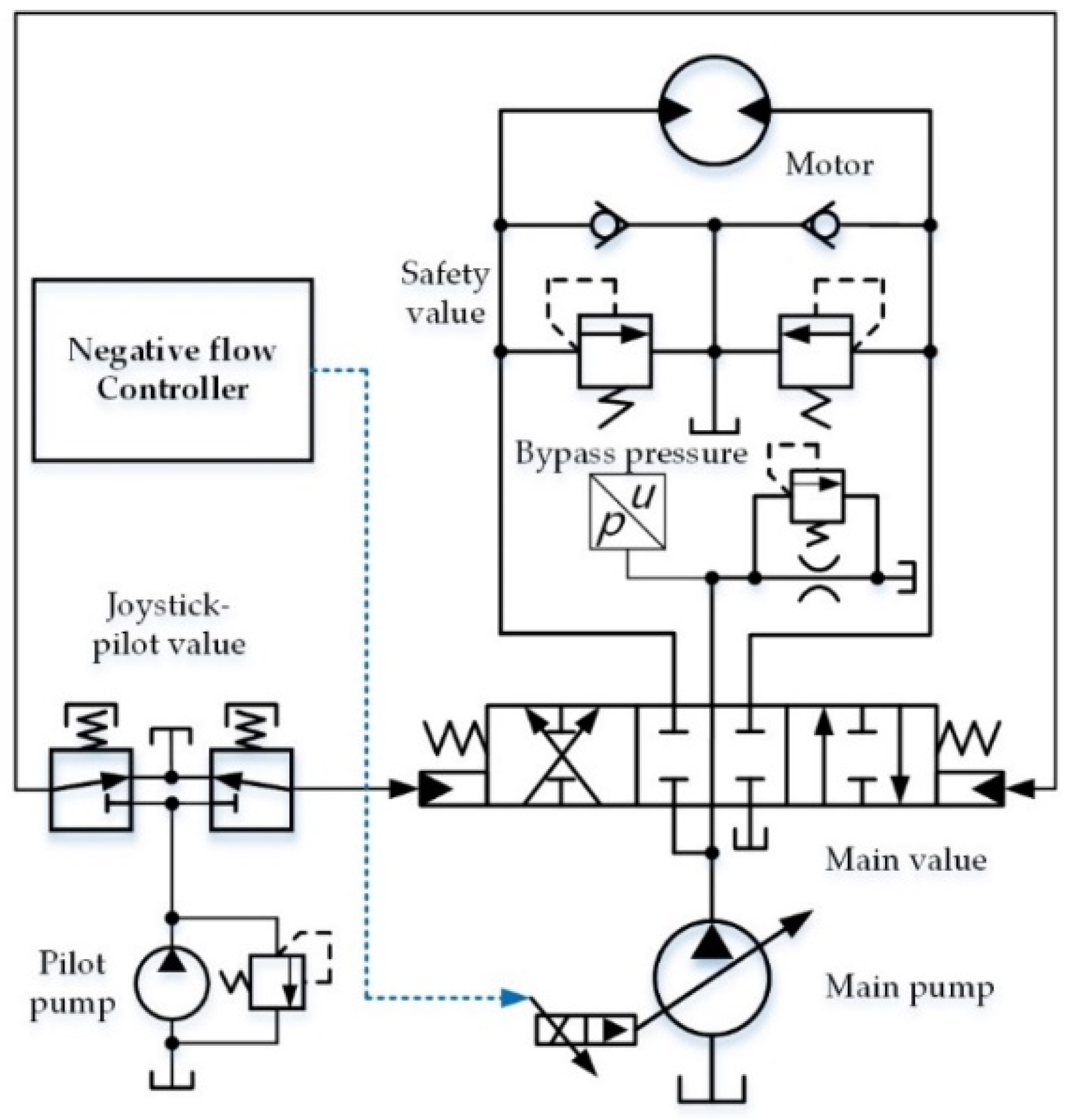
2.1. Original Negative Control Swing System
The working principle of the original negative control swing system is shown in
Figure 1. The system mainly includes a main pump, negative controller, main valve, swing motor, pilot pump, pilot valve, and so on. The system adjusts pump displacement according to negative feedback pressure and keeps bypass flow within a small range [
21].
In the system shown in
Figure 1, main valve opening is manually adjusted by joystick-main valve, it is difficult for operators to match main valve flow with the time-varying demands of motor in real time, which causes overflow loss during motor acceleration, thereby reducing system energy efficiency.
Long response time is a poor dynamic of a negative control system. There are a large number of intermediate links in the negative control process from the moment joystick issues control signal to the moment the pump displacement adapts to system requirements, which makes the system respond slowly. In addition, negative feedback pressure is easily disturbed by load pressure and it does not change significantly when the main valve leaves its neutral position and load pressure is too high, which leads to a longer response time [
22].
Braking stability is an important system dynamic that needs to be improved. During the braking process of a swing motor, the motor inlet and outlet are quickly closed. Under the action of inertial load, the working chamber at motor outlet generates brake pressure. When motor speed decreases to zero, the working chamber releases brake pressure and transmits power to the motor, which causes huge pressure and flow fluctuations, and the swing motor reverses and oscillates accordingly.
In summary, although main valve bypass power loss is reduced by negative control, the energy efficiency and dynamic of the original swing system still need to be improved.
2.2. Electro-Hydraulic Negative Control Swing System
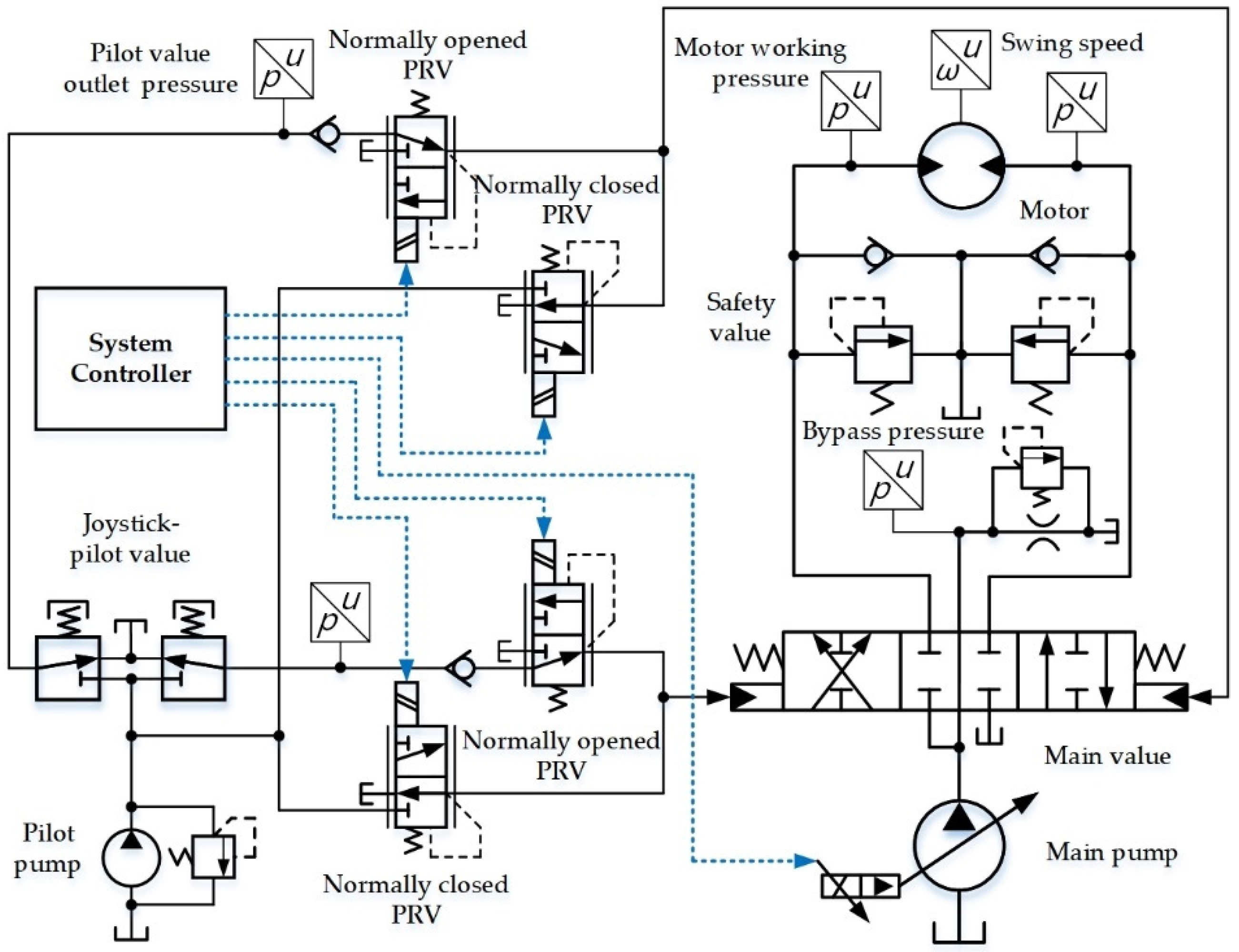
In order to reduce motor overflow and improve the dynamic of the original swing system, this paper proposes an electro-hydraulic swing system with adjustable main valve pilot pressure, as shown in
Figure 2. The difference between the electro-hydraulic system and the original system has only two aspects. First, main valve pilot control types are different. The original one adopts hydraulic controlled type, while the other one adopts electro-hydraulic controlled type. Second, control signals for adjusting pump displacement are different. In the original system, the control signal is negative feedback pressure. In the electro-hydraulic system, there are two types of control signals, namely negative feedback pressure and joystick-pilot pressure. However, the electro-hydraulic system essentially only reshapes the human command signal without changing other control characteristics, and the technical scheme can also be applied to other hydraulic systems with hydraulic controlled main value, such as the positive control system and load-sensing control system.
As shown in
Figure 2, there are two PRVs in the main valve control circuit, and the normally closed PRV is connected between main valve and pilot pump, the normally opened PRV is connected between the main valve and joystick-pilot valve. The normally opened PRV is used to reduce main valve pilot pressure, and the normally closed PRV is used to increase main valve pilot pressure. Therefore, the main valve opening can be adjusted arbitrarily by controlling the two PRVs. Pressure sensors are installed to detect motor inlet pressure and outlet pressure, joystick-pilot pressure. A speed sensor is installed to detect angular velocity of the swing motor. The system controller performs compound control on these PRVs and the main pump according to working conditions, the pressure and flow of motor inlet and outlet are dynamically adjusted to a desired state that the system has better energy efficiency and dynamic.
3. Control Strategy
This paper proposes a pump-value compound control strategy for the electro-hydraulic swing system, and its basic idea is as follows. During the acceleration of the swing motor, limit motor working pressure by controlling the main pump or PRVs, thereby reducing the overflow. During the braking process of the swing motor, open the channel from motor to tank to reduce motor brake pressure before swing speed decreases to zero, thereby reducing the motor pressure and flow fluctuation.
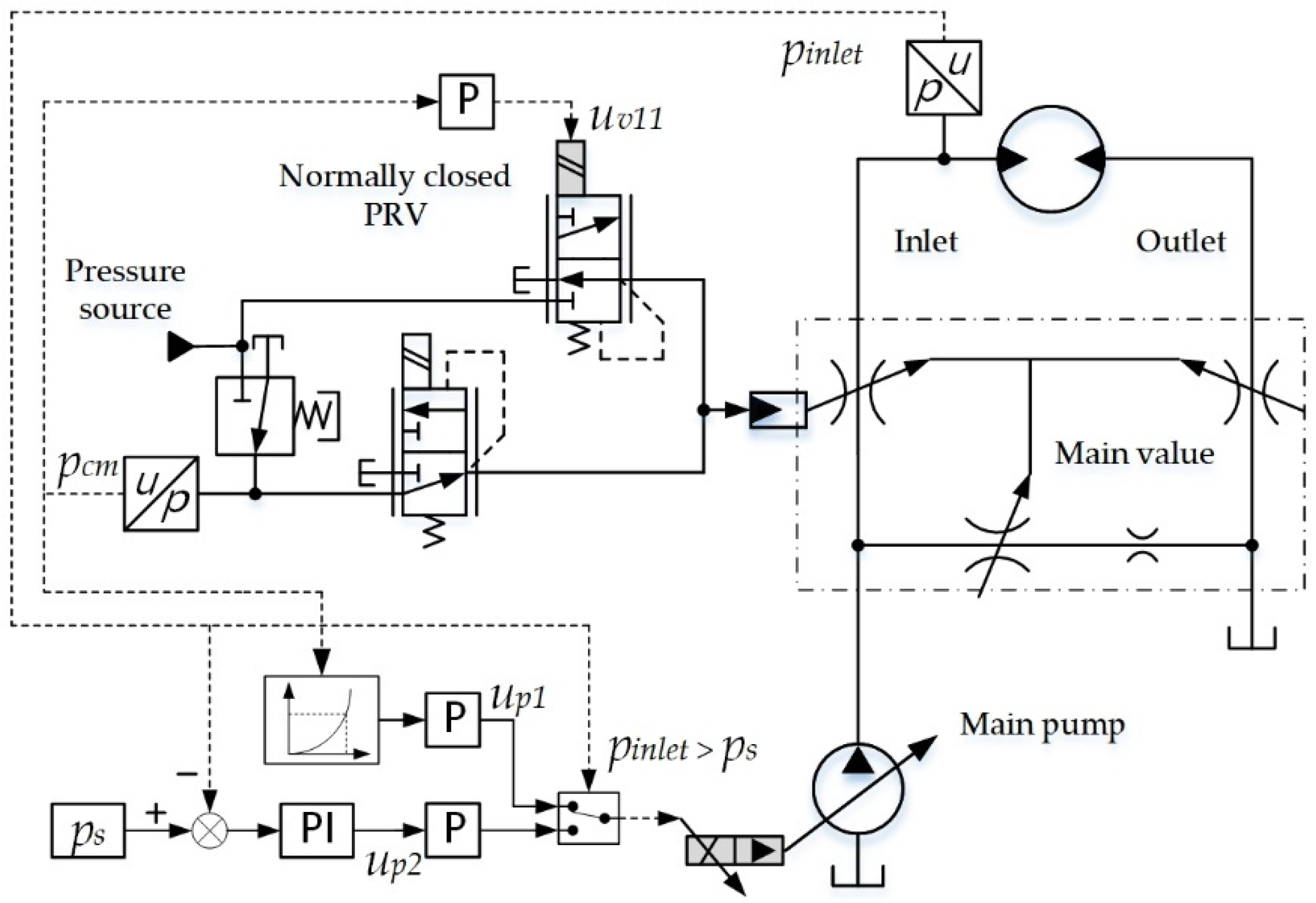
3.1. Motor Acceleration Control
3.1.1. Single-Swing Action
It can be determined that the excavator is working in single-swing condition when system working conditions meet the following conditions.
where
is swing joystick-pilot pressure,
is other joystick-pilot pressure. The system controller adjusts the main valve pilot pressure to maximum when the excavator performs a single-swing action. A proportional link P is set between
and the normally closed PRV, and the control signal of the PRV
should be set as
where
is proportional gain (
) of the normally closed PRV, and it should be large enough to fully open the PRV with a small joystick-pilot pressure. In order to form a certain proportional relationship between joystick stroke and motor speed, the control signal of main pump
needs to be set as
where
is proportional gain (
) of main pump,
is the minimum pilot pressure that can adjust main pump displacement. According to Formula (3), the proportional control range between joystick-pilot pressure and motor speed can be adjusted by setting parameters
and
. In addition, the number of intermediate control links for pump control is reduced, and the system response time can be reduced accordingly.
If the motor inlet pressure is greater than safety pressure, PI (proportional integral) controller can be used to reduce pump displacement, and then reduce the overflow. Here, motor inlet pressure
is the controlled quality of PI controller, and preset pressure
of PI controller is equal to motor safety pressure. When motor inlet pressure meets the following condition,
the control signal of main pump
can be set as
where
is deviation between preset pressure and motor inlet pressure,
is the proportional coefficient (
), and
is the integral coefficient (
). According to the experiment,
can be between 1 and 10, and
can be between 0.1 and 1. Shown in
Figure 3 is a schematic diagram of the motor acceleration control strategy when the excavator performs a single-swing action.
3.1.2. Compound-Swing Action
It can be determined that the excavator is working in compound-swing condition when the system working conditions meet the following conditions.
When the excavator performs a compound-swing action of two actuators, the flow of swing motor and a hydraulic cylinder is supplied by one pump. However, when the cylinder reaches its limit position and the motor is still accelerating, it is prone to overflow due to mismatch between main valve flow and motor demand flow. In this working condition, negative control is still adopted for the main pump, and PI control is adopted for the normally opened PRV to reduce main valve opening, and the control signal of the PRV
can be set as
where
is the proportional coefficient (
),
is the integral coefficient (
). According to experiment,
can be between 1 and 10, and
can be between 0.1 and 1. At the moment that the motor inlet pressure is greater than the safety pressure, as shown in the following formula,
The controller sends the signal
to the normally opened PRV, and the pressure-reducing effect of the PRV is enhanced, the main valve opening is reduced accordingly, so that the oil flowing into motor is reduced, and the overflow is also reduced. Shown in
Figure 4 is a schematic diagram of the motor acceleration control strategy when the excavator performs a compound-swing action.
3.2. Motor Braking Control
As mentioned before, when the swing speed decreases to zero, the chamber at the motor outlet releases its pressure and outputs power to motor which makes the motor swing in reverse. In order to solve this problem, it is necessary to open the main valve to release hydraulic brake pressure in advance.
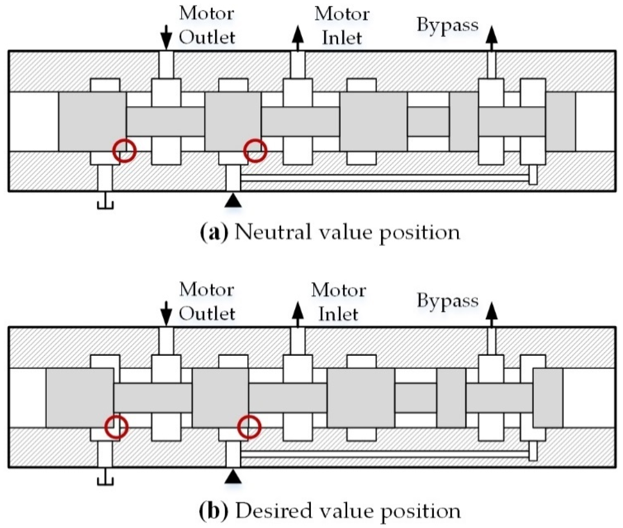
According to the pressure and flow characteristic curve of the main valve, when it is in the neutral position, its overlap at motor inlet is greater than that at motor outlet (as shown in
Figure 5a). During the opening process of the main valve, the motor outlet is always opened before its inlet. Therefore, this paper formulates a braking control strategy as follows. Before motor speed decreases closed to zero, system controller increases the main valve opening to open the channel from motor outlet to tank, and keep the motor inlet channel closed (as shown in
Figure 5b).
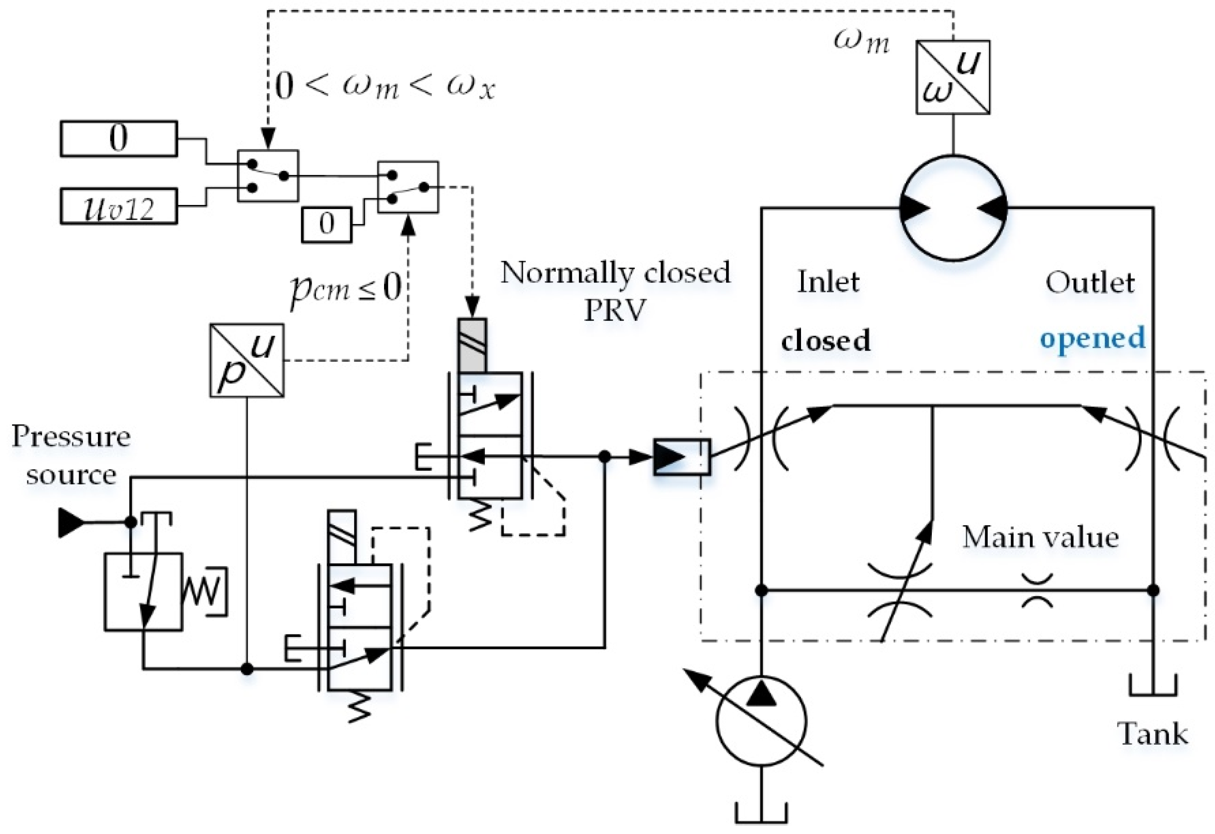
When the swing motor is braking and its speed is close to zero, system operating parameters must meet the following conditions.
where
is the motor speed;
is the motor speed that can activate the controller for motor braking control. At this working condition, the system controller needs to send a control signal
to the normally closed PRV to move the spool to the position shown in
Figure 5b, and the control signal can be expressed as
where
is a constant (
), and it can be obtained through multiple tests. As shown in
Figure 6, it is the schematic diagram of the motor braking control strategy.
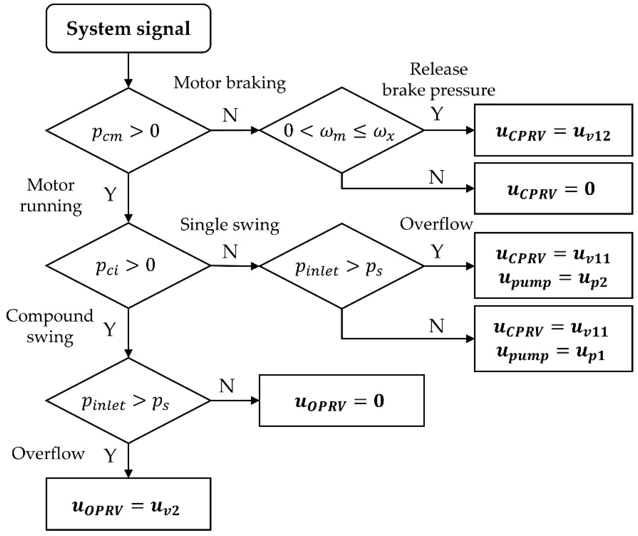
In summary, in
Figure 7, a control flowchart is shown to visualize the switching conditions of the above three control strategies. In the flowchart,
is the control signal of normally closed PRV,
is the control signal of normally opened PRV,
is the control signal of the main pump. In addition, each box represents a working mode, the value of these control signals not shown in each box are all zero.
4. Simulation
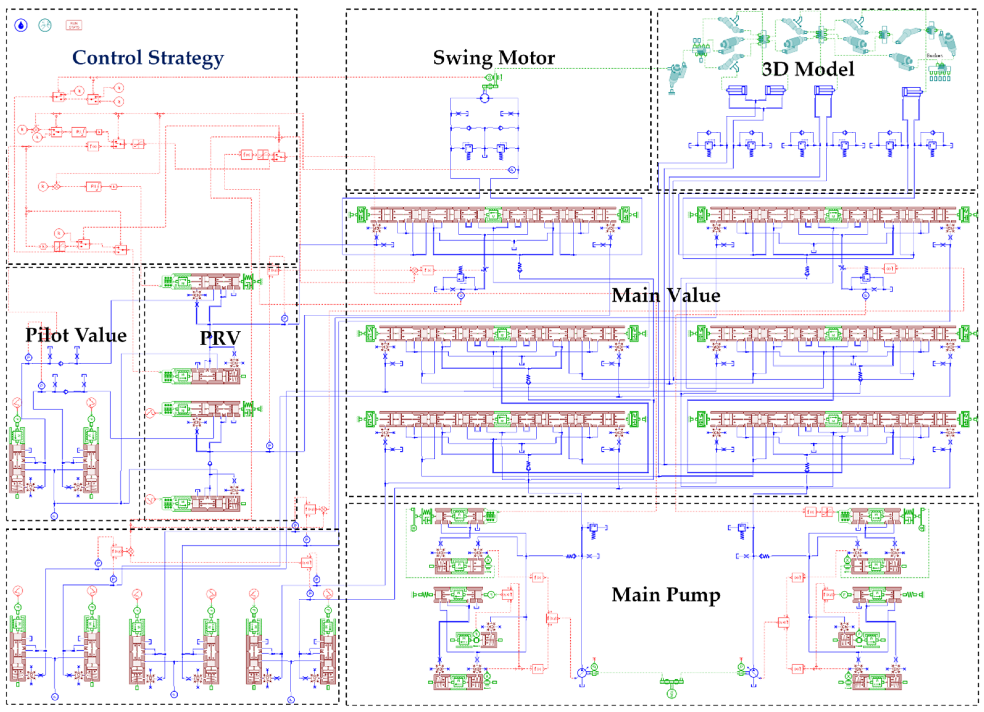
In order to investigate the feasibility and correctness of the proposed technical scheme and control strategies, as shown in
Figure 8, a simulation model of a 37-ton excavator was established with manufacturing data, but not validated for all operating points. The swing motion of the excavator was simulated with the model, and the original and optimized system performance were compared and analyzed, thus verifying the control concept of this paper.
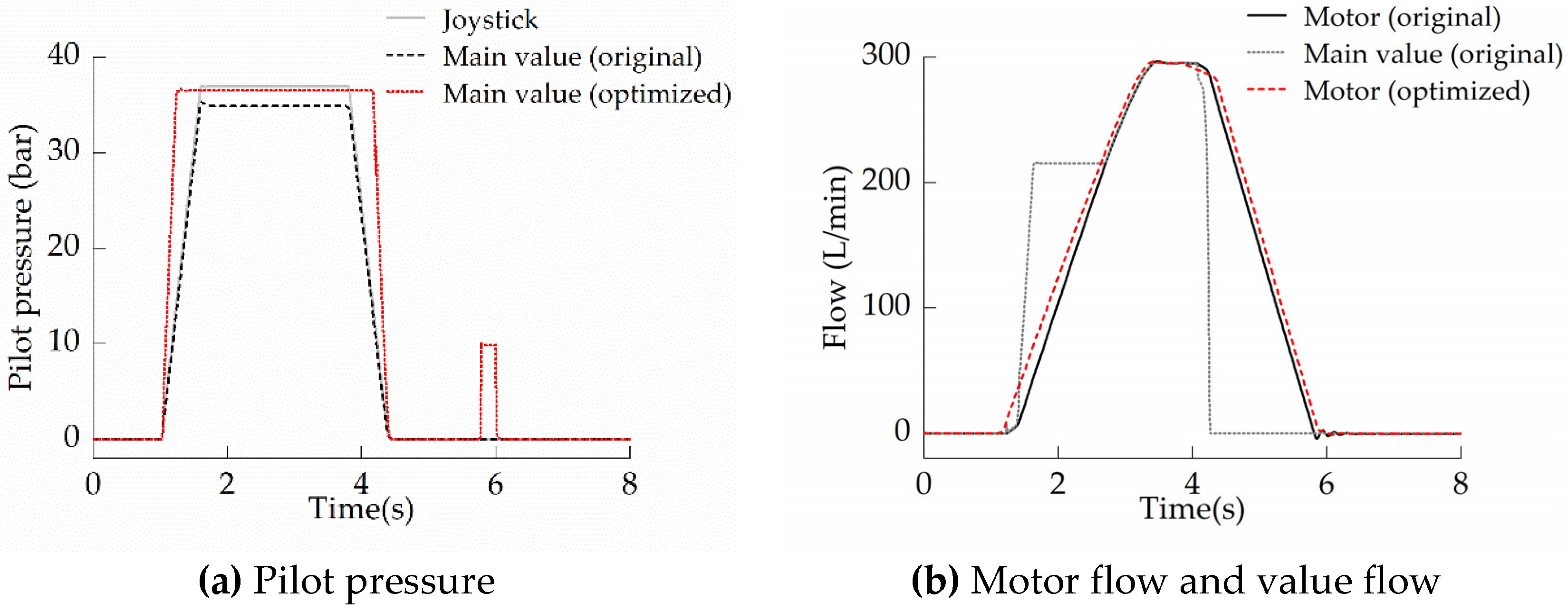
4.1. Single-Swing Action
When excavator performs a single-swing action, the operational characteristics of the two swing systems are shown in
Figure 9.
In order to simulate the system operation more realistically when the operator quickly operates joystick, trapezoidal wave was used to simulate joystick control signal. Joystick-pilot pressure and main value pilot pressure are shown in
Figure 9a. As shown in
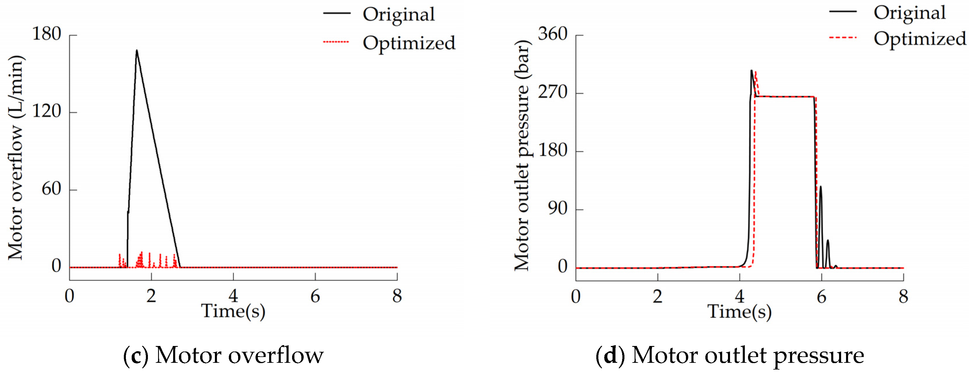
Figure 9b, in the original system, pump displacement is adjusted by negative feedback pressure, the motor flow begins to increase at about 1.25 s. In the optimized system, pump displacement is directly adjusted by joystick, the motor flow begins to increase rapidly at about 1.1 s, and its response speed is faster than that of the negative control system. Due to the inertia of the rotary platform, the swing motor cannot fully absorb main valve flow, however, the motor’s ability to absorb hydraulic oil is enhanced as the motor flow (speed) increases, and motor overflow decreases accordingly. As shown in
Figure 9c, after the proposed control strategy is adopted, the controller reduces pump displacement when the motor inlet pressure exceeds the preset pressure of PI controller, and most of motor overflow is eliminated.
In order to shorten the response time of motor acceleration, the proportional coefficient
needs to be a relatively large value, which makes the main valve pilot pressure increase faster than the original, as shown in
Figure 9a. However, if this proportional coefficient is too large, it will cause the main valve pilot pressure to lag behind joystick-signal seriously in the motor braking process. Therefore, as shown in
Figure 9b, the beginning time of motor braking (at about 4.3 s) of the optimized system is later than that of negative control system (at about 4.2 s). When motor speed decreases close to zero, main valve pilot pressure increases between 5.8 and 6.1 s, the channel from motor outlet to tank is opened, and hydraulic brake pressure is released. Subsequently, motor flow and pressure fluctuations are quickly attenuated, as shown in
Figure 9b,d. Thus, the braking stability of the swing system is improved.
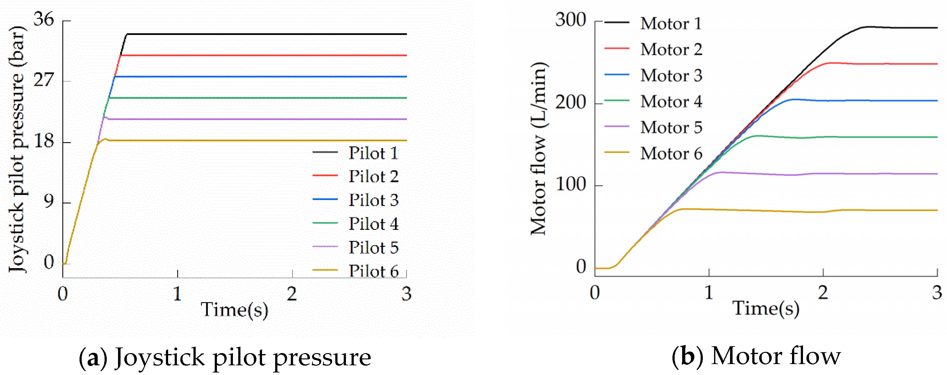
In addition, the proportional control range of six-way type main valve is narrow and uncertain, because it has a large dead zone in its neutral position and its proportional control range is also easily affected by load pressure. However, in single-swing action, if swing system adopts the volumetric speed control strategy, a certain proportional relationship can be established between motor flow and joystick-pilot pressure. The six joystick-pilot pressure curves are shown in
Figure 10a, the corresponding motor flow curves are shown in
Figure 10b, and it can be seen that they have a good proportional relationship.
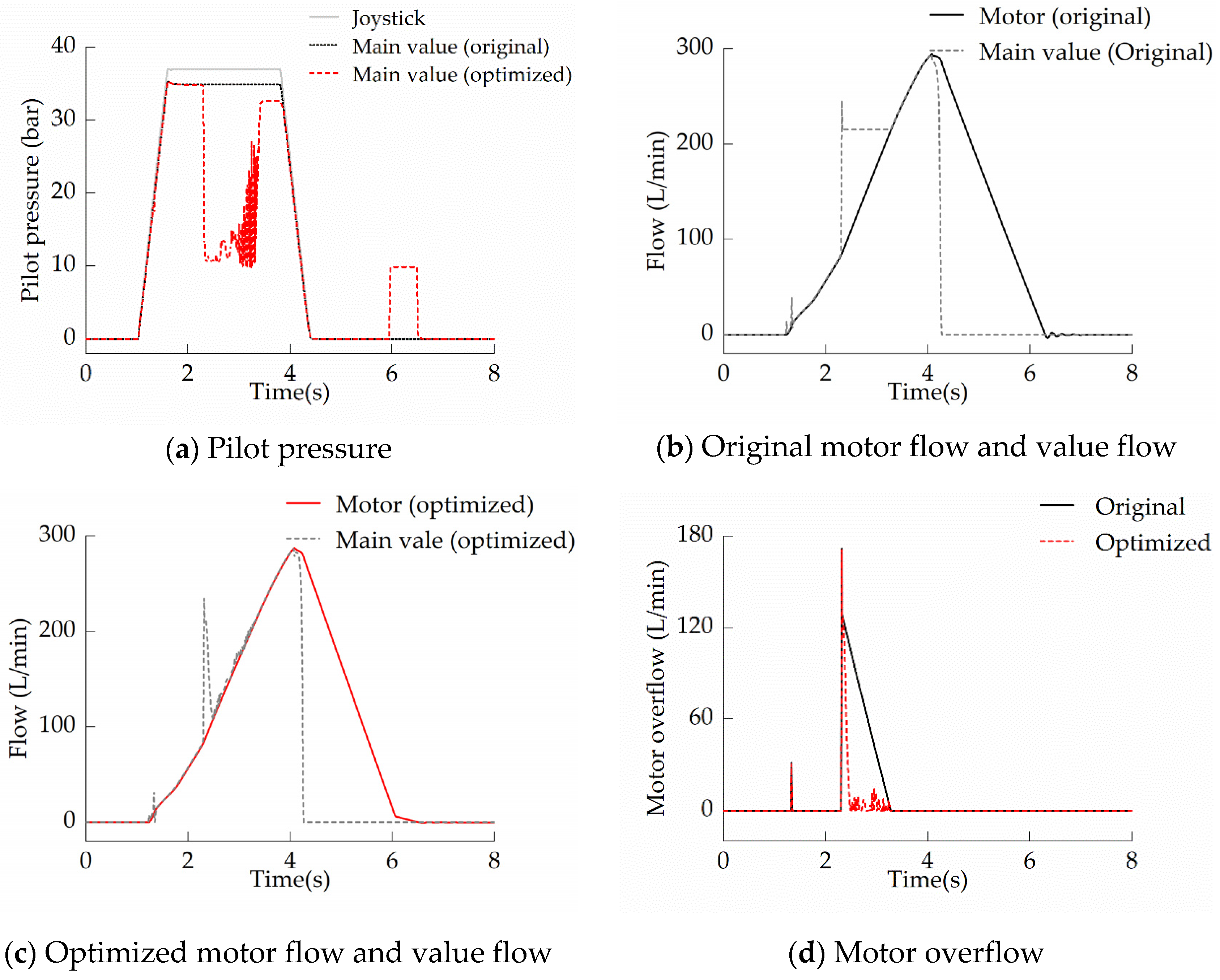
4.2. Compound-Swing Action
This paper presents a simulation result when the excavator performs a compound action of dipper and rotary platform, and the operational characteristics of the two swing systems are shown in
Figure 11.
As shown in
Figure 11a, if the system adopts the proposed control strategy, the normally opened PRV have a certain influence on main value pilot pressure. As shown in
Figure 11b, between 1.3 and 2.3 s, the swing motor and dipper cylinder are supplied with oil by a main pump, and the working pressure of the swing motor is limited by the working pressure of the dipper cylinder. Due to the low dipper load, motor working pressure is also low, and motor flow increases slowly and rarely overflows. At about 2.2 s, the dipper cylinder reaches its limit position, and the motor working pressure is only limited by safety valve, at this moment, main valve flow is greater than the absorption capacity (motor outlet flow) of the swing motor. As shown in
Figure 11c,d, the PI controller reduces the main valve opening by controlling the normally opened PRV, thereby reducing the flow from main valve into the swing motor. In addition, optimization of swing braking stability in compound-swing action is the same as in single-swing action.
5. Conclusions
In order to reduce motor overflow and improve the dynamic of original negative control swing system, this paper proposes an improvement scheme for main valve pilot control circuit, and it enables main valve pilot pressure to be adjusted arbitrarily. According to the different working conditions of the swing system, three motor control strategies were formulated. The results of this study indicate that the new scheme has the following improvements.
First, during single-swing motor acceleration, the electro-hydraulic swing system limits the motor inlet pressure to its relief pressure by controlling pump displacement, motor overflow and system response time are effectively reduced. In addition, the volumetric speed control method with joystick-motor positive control link can establish a good proportional relationship between joystick-pilot pressure and motor flow.
Second, during compound-swing motor acceleration, the electro-hydraulic swing system reduces the flow from the main valve to motor by controlling the normally opened PRV, and the motor overflow is also reduced.
Third, during motor braking, at the moment that swing speed decreases close to zero, the channel from the motor to tank is opened by normally closed PRV. As a result, the brake pressure in the motor working chamber at motor outlet is released in advance, which weakens the fluctuation of motor pressure and flow. Thus, swing braking stability is improved.
Author Contributions
Conceptualization, L.Z. and W.F.; methodology, W.F.; software, W.F. and X.Y.; validation, Z.M.; formal analysis, Z.M.; investigation, L.Z.; resources, X.Y.; data curation, X.Y.; writing—original draft preparation, W.F.; writing—review and editing, L.Z.; visualization, Z.M.; supervision, X.Y.; project administration, X.Y.; funding acquisition, L.Z. All authors have read and agreed to the published version of the manuscript.
Funding
This work was supported by the National Key Research and Development Project of China (2018YFB2001202) and Open Foundation of the State Key Laboratory of Fluid Power and Mechatronic Systems (GZKF-201820).
Conflicts of Interest
The authors declare no conflict of interest.
References
- Tongji University. Single Bucket Hydraulic Excavator, 2nd ed.; China Architecture & Building Press: Beijing, China, 1986; p. 143. [Google Scholar]
- Vašina, M.; Hružík, L.; Bureček, A. Energy and dynamic properties of hydraulic systems. Teh. Vjesn. 2018, 25, 382–390. [Google Scholar]
- Xu, B.; Liu, W.; Yang, H.; Zhang, S. Experiment study on flow compensation of electro-hydraulic flow matching control system in hydraulic excavator. J. Zhejiang Univ. 2012, 46, 1382–1389. [Google Scholar]
- Cheng, M.; Zhang, J.; Xu, B.; Ding, R. Electrohydraulic Load Sensing System via Compound Control of Flow Feedforward and Pressure Feedback. J. Mech. Eng. 2018, 54, 262–270. [Google Scholar] [CrossRef]
- Uehara, K.; Tominaga, H. Energy Saving on Hydraulic Systems of Excavators. SAE Trans. 1982, 91, 3332–3346. [Google Scholar]
- Gao, F.; Pan, S. Experimental study on model of negative control of hydraulic system. J. Mech. Eng. 2005, 41, 107–111. [Google Scholar] [CrossRef]
- Gu, L.; Wang, Q.; Lu, Y. Research on acceleration and deceleration characteristic for high inertia loads driven by hydraulic. J. Mech. Eng. 2002, 38, 46–49. [Google Scholar] [CrossRef]
- Huang, W.; Quan, L.; Huang, J.H. Excavator Swing System Controlled with Separate Meter-in and Meter-out Method. J. Mech. Eng. 2016, 52, 159–167. [Google Scholar] [CrossRef]
- Jin, K.; Park, T.; Lee, H. A control method to suppress the swing vibration of a hybrid excavator using sliding mode approach. Proc. Inst. Mech. Eng. Part C J. Mech. Eng. Sci. 2012, 226, 1237–1253. [Google Scholar] [CrossRef]
- Yu, Y.; Ahn, K.K. Improvement of Energy Regeneration for Hydraulic Excavator Swing System. Int. J. Precis. Eng. Manuf. Green Technol. 2020, 7, 53–67. [Google Scholar] [CrossRef]
- Yu, Y.X.; Ahn, K.K. Energy regeneration and reuse of excavator swing system with hydraulic accumulator. Int. J. Precis. Eng. Manuf. Green Technol. 2019, 1–15. [Google Scholar] [CrossRef]
- Yan, Y.Q.; He, Y.C.; Meng, Z.M.; Kang, S.S. The Research on Based on Secondary Regulation of Swing System of Hydraulic Excavator. Adv. Mater. Res. 2014, 845–849. [Google Scholar] [CrossRef]
- Yao, H.; Wang, Q. Control strategy for hybrid excavator swing system driven by electric motor. IFAC Proc. Chamb. 2013, 46, 109–115. [Google Scholar] [CrossRef]
- Wang, C.; Quan, L. Methods of Restrain the Hydraulic Impact with Active Adjusting the Variable Damping in System with Large Inertia Load. J. Mech. Eng. 2014, 50, 182–188. [Google Scholar] [CrossRef]
- Khalid, A.; Huey, J.; Singhose, W.; Lawrence, J.; Frakes, D. Human Operator Performance Testing Using an Input-Shaped Bridge Crane. J. Dyn. Syst. Meas. Control 2006, 128, 835–841. [Google Scholar] [CrossRef]
- Kjelland, M.B.; Hansen, M.R. Using input shaping and pressure feedback to suppress oscillations in swing motion of lightweight flexible hydraulic crane. Int. J. Fluid Power 2015, 16, 141–148. [Google Scholar] [CrossRef]
- Fodor, S.; Vázquez, C.; Freidovich, L. Automation of swing motions for forestry cranes. In Proceedings of the 2015 15th International Conference on Control, Automation and Systems (ICCAS), Busan, Korea, 13–16 October 2015. [Google Scholar]
- Fodor, S.; Vázquez, C.; Freidovich, L. Towards oscillation reduction in forestry cranes. In Fluid Power Systems Technology; American Society of Mechanical Engineers: Bath, UK, 2016. [Google Scholar]
- Ng, F.; Harding, J.A.; Glass, J. An eco-approach to optimise efficiency and productivity of a hydraulic excavator. J. Clean. Prod. 2016, 112, 3966–3976. [Google Scholar] [CrossRef]
- Xu, B.; Cheng, M. Motion control of multi-actuator hydraulic systems for mobile machineries: Recent advancements and future trends. Front. Mech. Eng. 2018, 13, 151–166. [Google Scholar] [CrossRef]
- Yang, H.; Cao, J.; Xu, B.; Wu, G. Progress in the evolution of directional control valves and future trends. J. Mech. Eng. 2005, 41, 1–5. [Google Scholar] [CrossRef]
- Gao, F.; Pan, S. A Sensing Control System of Negative Load. Trans. Chin. Soc. Agric. Mach. 2005, 36, 111–113. [Google Scholar]
© 2020 by the authors. Licensee MDPI, Basel, Switzerland. This article is an open access article distributed under the terms and conditions of the Creative Commons Attribution (CC BY) license (http://creativecommons.org/licenses/by/4.0/).


