Article

Experimental Analysis of the Performance and Load Cycling of a Polymer Electrolyte Membrane Fuel Cell

by
Andrea Ramírez-Cruzado
1,†,
Blanca Ramírez-Peña
1,†,
Rosario Vélez-García
1,†,
Alfredo Iranzo
1,2,* and
José Guerra
1
1
Thermal Engineering Group, Energy Engineering Department, School of Engineering, University of Sevilla, Camino de los Descubrimientos s/n, 41092 Sevilla, Spain
2
AICIA (Andalusian Association for Research & Industrial Cooperation)—Thermal Engineering Group, Camino de los Descubrimientos s/n, 41092 Sevilla, Spain
*
Author to whom correspondence should be addressed.
Contributed equally to this work.
Processes 2020, 8(5), 608; https://doi.org/10.3390/pr8050608
Submission received: 17 April 2020 / Revised: 5 May 2020 / Accepted: 11 May 2020 / Published: 20 May 2020
(This article belongs to the Special Issue Representative Model and Flow Characteristics of Fuel Cells)

Abstract

:
In this work, a comprehensive experimental analysis on the performance of a 50 cm2 polymer electrolyte membrane (PEM) fuel cell is presented, including experimental results for a dedicated load cycling test. The harmonized testing protocols defined by the Joint Research Centre (JRC) of the European Commission for automotive applications were followed. With respect to a reference conditions representative of automotive applications, the impact of variations in the cell temperature, reactants pressure, and cathode stoichiometry was analyzed. The results showed that a higher temperature resulted in an increase in cell performance. A higher operating pressure also resulted in higher cell voltages. Higher cathode stoichiometry values negatively affected the cell performance, as relatively dry air was supplied, thus promoting the dry-out of the cell. However, a too low stoichiometry caused a sudden drop in the cell voltage at higher current densities, and also caused significant cell voltage oscillations. No significant cell degradation was observed after the load cycling tests.

1. Introduction

Proton exchange membrane or polymer electrolyte membrane fuel cells (PEMFCs) are electrochemical devices that convert chemical energy directly to electrical energy with higher efficiencies than the ones corresponding to the Carnot thermodynamic cycles. Fuel cells are increasingly being deployed in the energy generation sector and also in the automotive sector, with major manufacturers focusing on both purely electric and PEMFC-based power-trains. For a further commercial deployment of the technology, it is widely recognized that both cost reductions and durability improvements are required [1,2]. One of the factors influencing fuel cell costs and durability is the operating conditions of the cell and the fuel cell stack, and it has therefore resulted in major research activities both in terms of experimental analysis [3,4,5,6] and development of modeling and simulation tools [7,8]. Optimizing the power output by adjusting the operating conditions is leading to more compact stacks, with a consequent reduction in materials and associated cost. In the same manner, adequate operating conditions help avoid excessive membrane drying/flooding or membrane temperate gradients that eventually lead to degradation [1,9]. More compact designs also enable a more suitable integration of fuel cell stacks in vehicle power trains and other applications such as unmanned aerial vehicles or unmanned underwater vehicles.
In most applications involving transient operation with load changes such as the ones mentioned previously, the operating conditions also vary and the operation is usually more severe to the fuel cell. When testing fuel cells at a lab-scale, testing should resemble real conditions, if possible. Several fuel cell testing protocols are available in the literature and comparisons among them have been developed in the work of Bloom et al. [10]. Regarding laboratory testing of fuel cells intended for automotive applications, the Joint Research Centre (JRC) of the European Commission (EC) has established a testing protocol based on realistic conditions being encountered in such applications [11], which has been agreed upon by different major manufacturers. This is therefore of significant importance when experimentally testing automotive fuel cells.
Based on the JRC testing protocol mentioned [11], this work presents a contribution covering experimental studies of a 50 cm2 PEM fuel cell, including the experimental results for a load cycling test. Cell performance, electrical efficiency, and cycling degradation studies are included in the experimental analysis.

2. Materials and Methods

2.1. Materials

The experiments were carried out in a fuel cell test bench equipped with a programmable load (ADAPTATIVE POWER 5L18-24, Adaptive Power Systems, Irvine, CA, United States) and the necessary Balance of Plant (BoP) to test a PEM Fuel Cell, including anode and cathode humidifiers based on DI water tanks (bubblers), and anode and cathode back-pressure regulators. The test bench was able to control the cell temperature and pressure, and the anode and cathode process variables such as volume flow, relative humidity (RH), pressure, and temperature. The test bench is depicted in Figure 1.
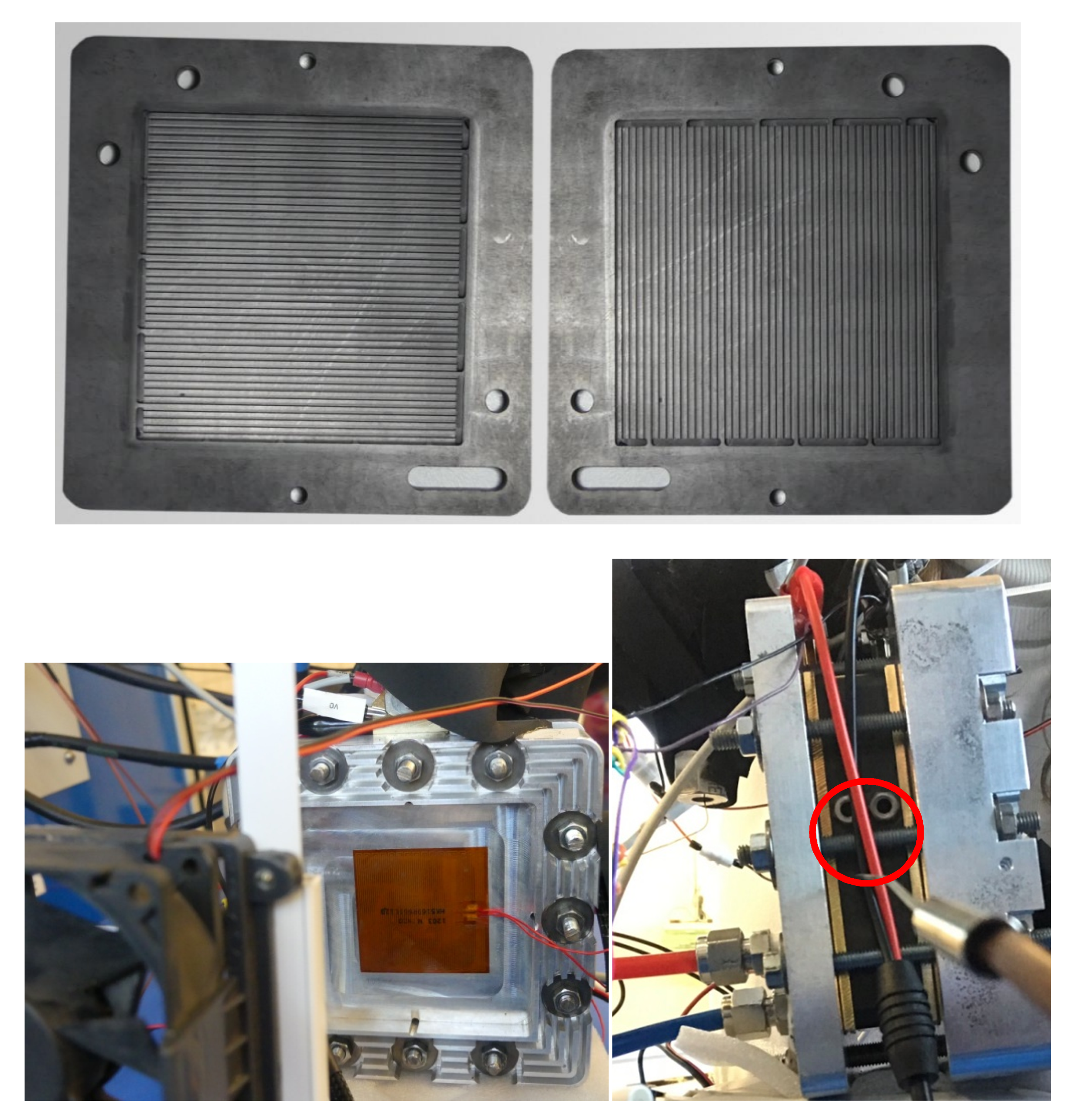
The fuel cell used in the experiments was a 50 cm2 single cell from ElectroChem Inc. (Woburn, MA, USA), with graphite bipolar plates featuring a cross-flow serpentine flow field (Figure 2). Vertical channels corresponded to the cathode side and the horizontal channels to the anode side. A Nafion 112 membrane (DuPont, Wilmington, Delaware, United States) was used in the experiments, where the catalyst layers were 1.0 mg Pt/cm2 in both anode and cathode. Toray TGP-H-060 GDLs (gas diffusion layers, GDLs by Toray Industries, Inc., Tokyo, Japan) were placed in the cell, without the micro porous layers (MPL). Silicon gaskets were used to ensure a tight configuration. On the outer sides of the cell film, heaters (Figure 2, bottom) as well as external air fans were placed in order to allow for an accurate temperature control.

2.2. Methods

The experimental testing methods that have been followed in the research work are described in the JRC harmonized testing protocols for automotive single fuel cells [11].
The objective of such protocols was to establish a methodology for a better comparison of the performance and durability achieved by different fuel cells (single cells). Operating conditions representative of automotive applications were proposed (the so-called reference conditions, as indicated in Table 1). The protocol also established expected ranges for the operating conditions for variables such as temperature, reactants pressure, and humidification, or stoichiometry. Load cycling experiments (applying a repetitive load profile to the cell) were also described in the protocol [11] and have been used in the current research work. The load cycle proposed in the protocol was based on the New European Driving Cycle [12].
The experimental tests carried out are presented in Table 1, where the reference conditions represent the benchmark conditions used for comparison, and the set of tests carried out were grouped by the variable being modified (cell temperature, reactants pressure, and cathode stoichiometry). All tests represent deviations from the reference conditions, which would result in changes to both cell performance and durability.
As indicted in Table 1, 80 °C was defined as the reference cell temperature. The cell temperature was measured at the center point of the side of the cathode monopolar plate in the single cell. As stated previously, a constant temperature was maintained during all experiments by means of electric heaters placed on both sides of the fuel cell (when external heating was required), or by means of external cooling fans placed on both sides of the cell (when external cooling was required, particularly at higher current densities).
A set of polarization curves in galvanostatic mode (including both forward and backward current) was performed for each condition depicted in Table 1. Before performing each set of polarization curves, the cell was conditioned according to the specifications provided in the testing protocol [11]. The set points for the polarization curves are included in Appendix A.
Regarding the load cycling tests, the objective was to carry them out in a laboratory environment and at a single cell level, by varying the power demands during vehicle operation, which is known to be a relevant source of stress on MEA performance and durability [13,14]. In the experiments, the load cycling tests were performed with the operating conditions corresponding to the reference conditions. As this was carried out at a laboratory-scale and not an industry-scale, only five cycles were repeated. The set points corresponding to the load cycling test and the procedures followed are described in Appendix B.

3. Results

This section presents the main results obtained in the experimental research performed. The cell performance corresponding to the reference conditions in Table 1 is presented first, followed by the different tests that were carried out (temperature, pressure, and cathode stoichiometry). Finally, the load cycling test is presented. An in-depth discussion of the results is introduced in Section 4. The raw experimental data of this work is described in Appendix C.

3.1. Cell Performance under Reference Conditions

The reference conditions were analysed first in order to provide a benchmark or reference curve for the cell performance.

3.1.1. Cell Conditioning

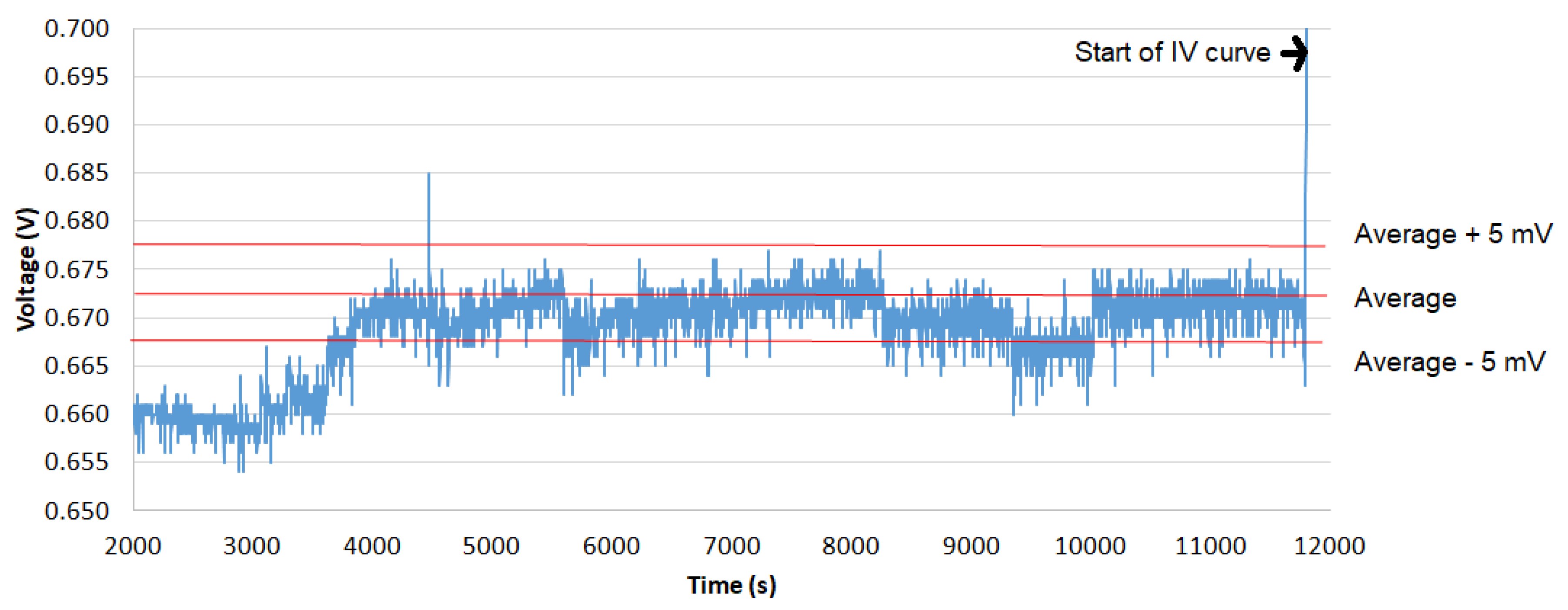
Cell conditioning is a mandatory step before any measurement of the polarization curve, and it aims at ensuring that the cell voltage achieves a constant value before starting any subsequent test. Once the desired operating conditions are defined for the cell, the criterion of constant voltage is defined by monitoring the cell voltages during a specified period [11], where variations must be within a range of +/−5 mV during the last hour, before the finalization of the cell conditioning.
In the experiments carried out, the conditioning step took around 3 h. The time evolution of the cell voltage during the conditioning step is depicted in Appendix D (Figure A2), showing the +/−5 mV criteria according to [11].

3.1.2. Polarization Curves

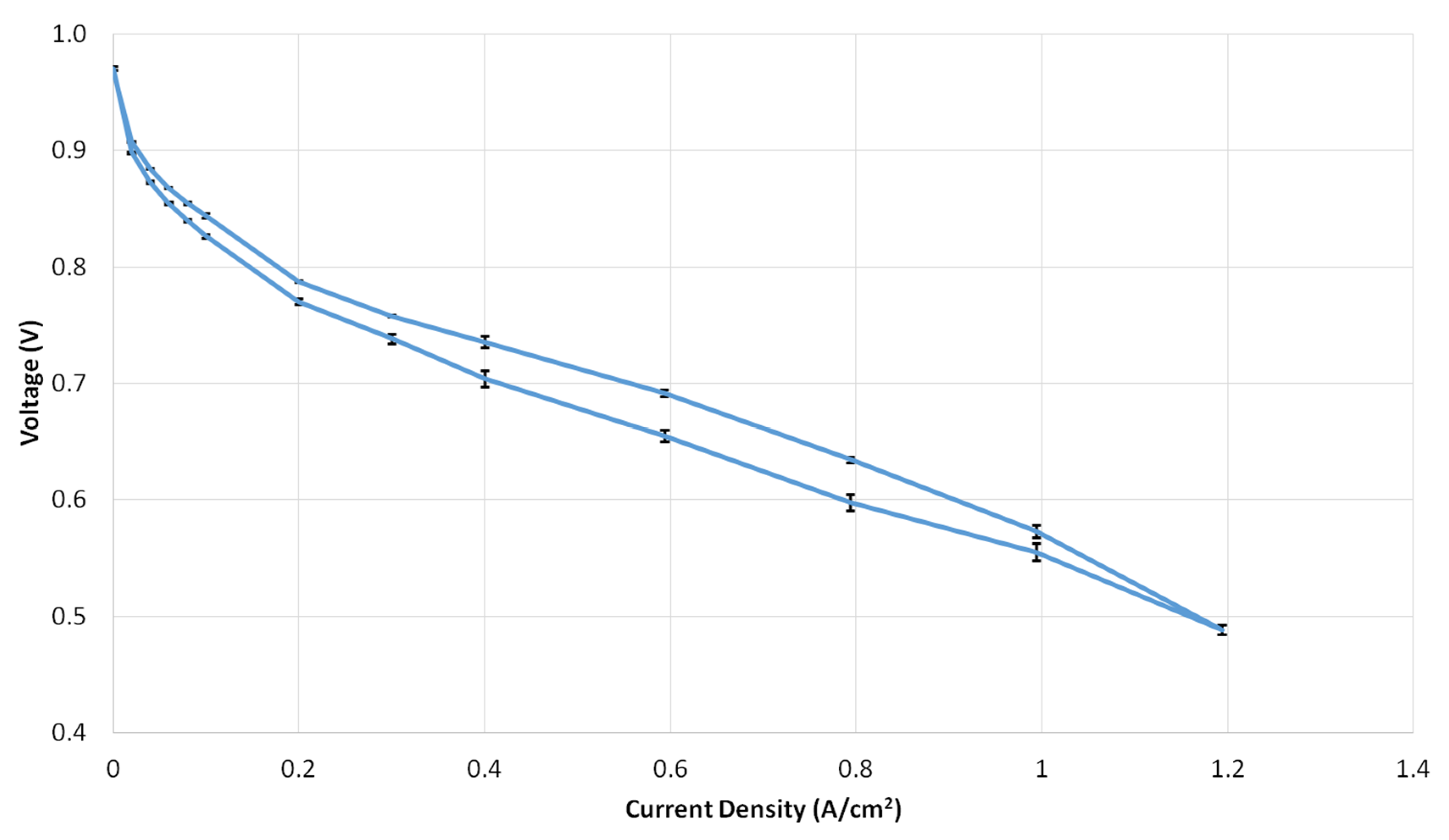
Once the cell conditioning step was finalized, the polarization curve experiment was started by following the set points indicated in Appendix A (Table A1). Both forward and backward curves were recorded, and the complete experiment was repeated three times in order to verify the reproducibility of the results. The resulting polarization curve corresponding to the reference conditions is depicted in Figure 3, where error bars were included to account for the three experiments carried out. The three polarization regions (activation, ohmic, mass transport) are clearly shown in the curve, and a hysteresis phenomenon can also be seen. The fact that the forward curve (increasing current) was below the backward curve (decreasing current) clearly indicates that there is a certain degree of dry-out in the cell [15,16], for the cell components and operating conditions specified. The polarization curve corresponding to the reference conditions was used as a benchmark case for the analysis of how deviations in the operating conditions affected the performance of the cell.

3.2. Temperature Tests

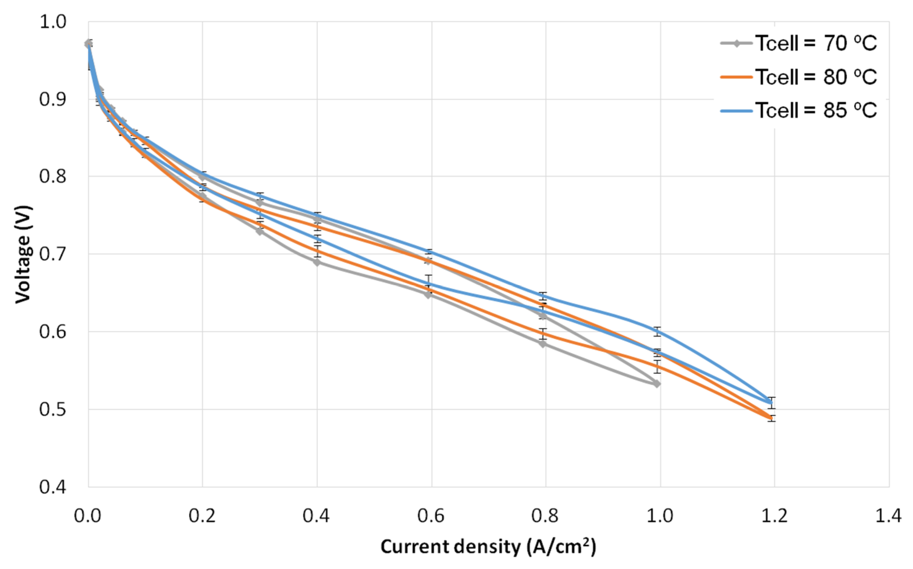
The operating temperature of the cell is an important parameter that affects both performance and durability. Membrane degradation can be accelerated by high temperature and high temperature gradients, and heat management highly influences the water management in the cell, resulting in excessive flooding or dry-out, depending on the temperature conditions. The objective of the temperature tests was to assess the cell performance variations when operating at the temperature values indicated in Table 1. The resulting polarization curves corresponding to the temperature tests in Table 1 are depicted in Figure 4, together with the reference condition curve, for comparison.

3.3. Pressure Tests

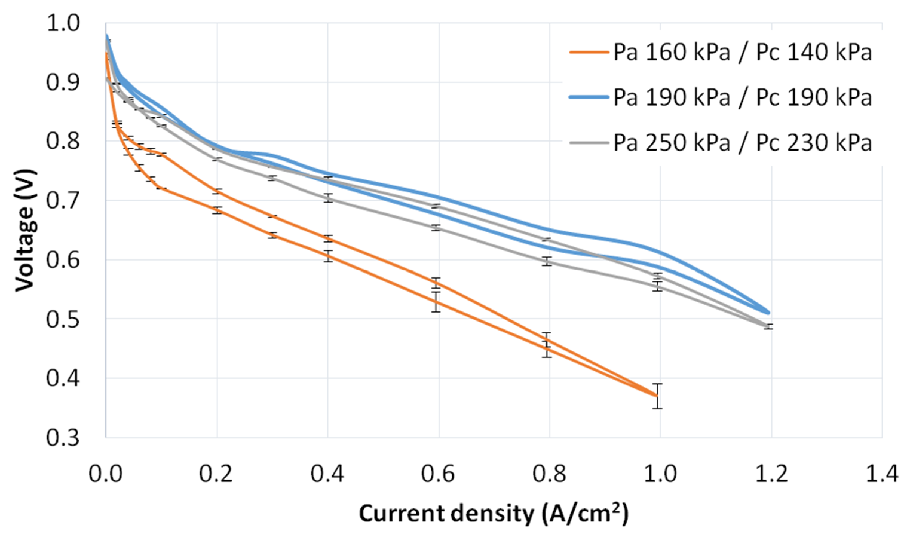
The objective of the pressure tests was to assess the cell performance variations when operating at the reactants pressure values indicated in Table 1. Pressure variations affected the fuel cell performance due to different phenomena, such as variation in open circuit voltage (OCV), fuel cross-over due to pressure differences, effects caused by the different partial pressure of reactants and water (electrochemical kinetics, liquid/vapor equilibrium), and mass transfer phenomena [11].
The resulting polarization curves corresponding to the pressure tests in Table 1 are depicted in Figure 5, together with the reference condition curve, for comparison.

3.4. Cathode Stoichiometry Tests

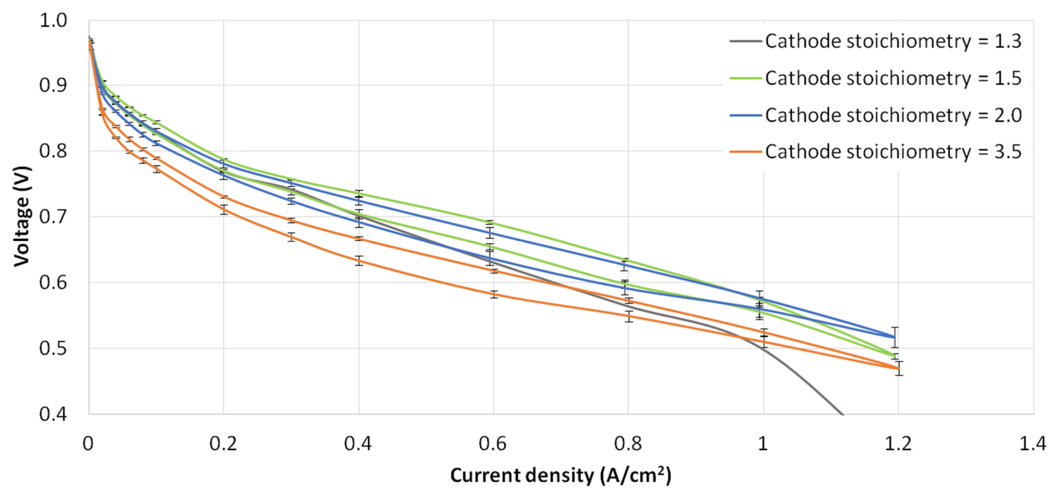
The objective of the cathode stoichiometry test was to assess the cell performance variations when operating at the reactants pressure values indicated in Table 1. The air mass flow being supplied to the cell had a clear influence in terms of oxygen transport, liquid water removal capability, and also membrane dry-out, depending on the relative humidity of the air. It also generated parasitic losses, as usually the air supply is managed by a compressor in final applications.
The resulting polarization curves corresponding to the cathode stoichiometry tests in Table 1 are depicted in Figure 6, together with the reference condition curve, for comparison.

3.5. Load Cycling Tests

The aim of the load cycling test was to assess the durability of the fuel cell under realistic driving conditions, characterized by load changes. Durability is a key parameter of fuel cells [13,14] and 5000 h are required for the fuel cells to be suitable for automotive applications (as defined by the DOE targets [17]). The cell durability can be evaluated by applying a repetitive load profile and consequent measuring of the performance degradation (cell voltage decrease vs. time or vs. number of cycles). The load cycling test defined in the protocol [11] is based on the New European Driving Cycle (NEDC) [12], although with appropriate modifications to account for the particular operation of fuel cells in automotive applications. Details on the load profile and the procedures for the application of the load cycling to the fuel cell are included in Appendix B.
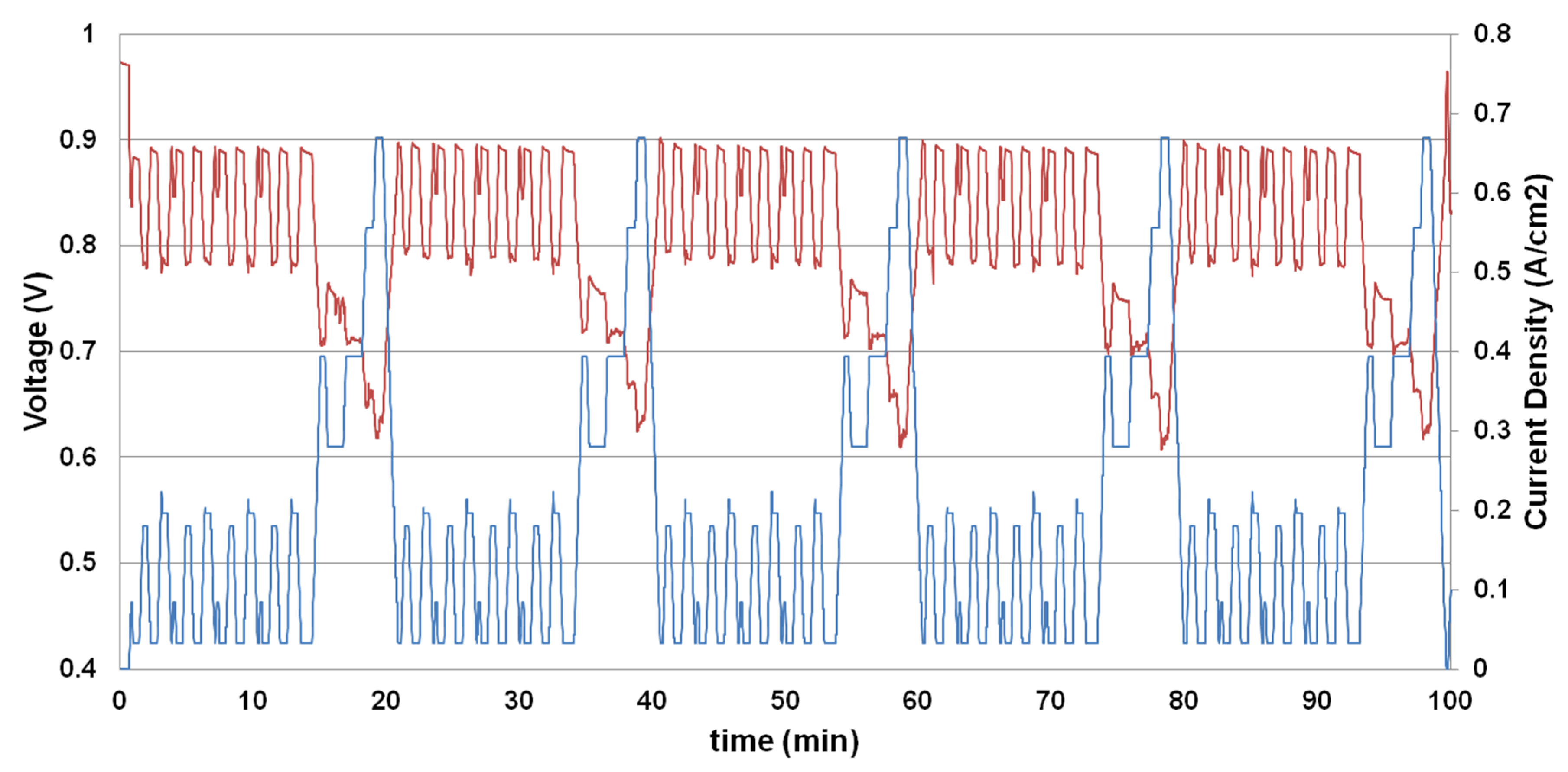
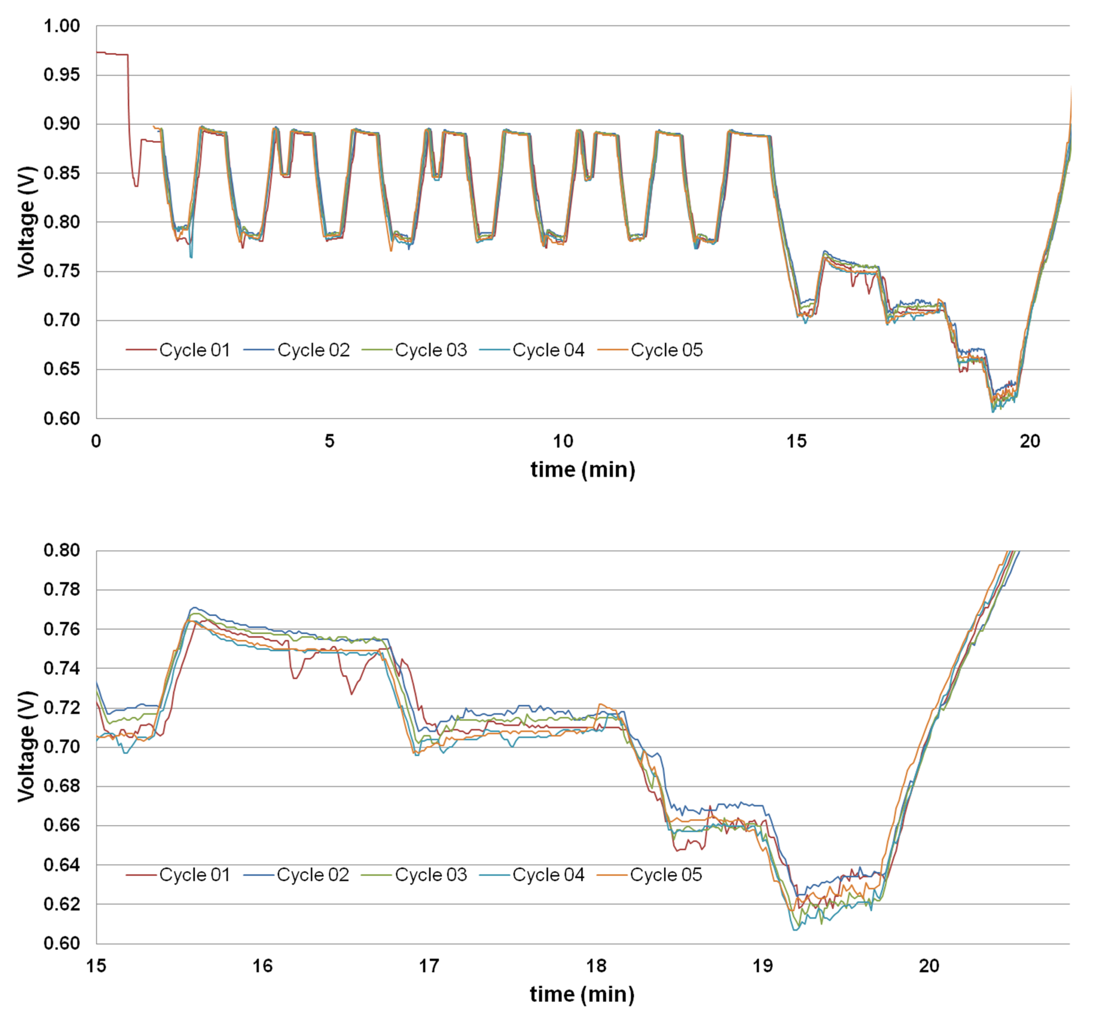
The load cycling experiment was performed with operating conditions corresponding to the reference conditions. As this was carried out at a laboratory-scale, only five cycles were repeated. The set points corresponding to the load cycling test and the procedures followed are described in Appendix B. The evolution of the cell voltage during the execution of the load cycle test is shown in Figure 7, where the superposition of the cycles is provided in Figure 8, for a better comparison between cycles.
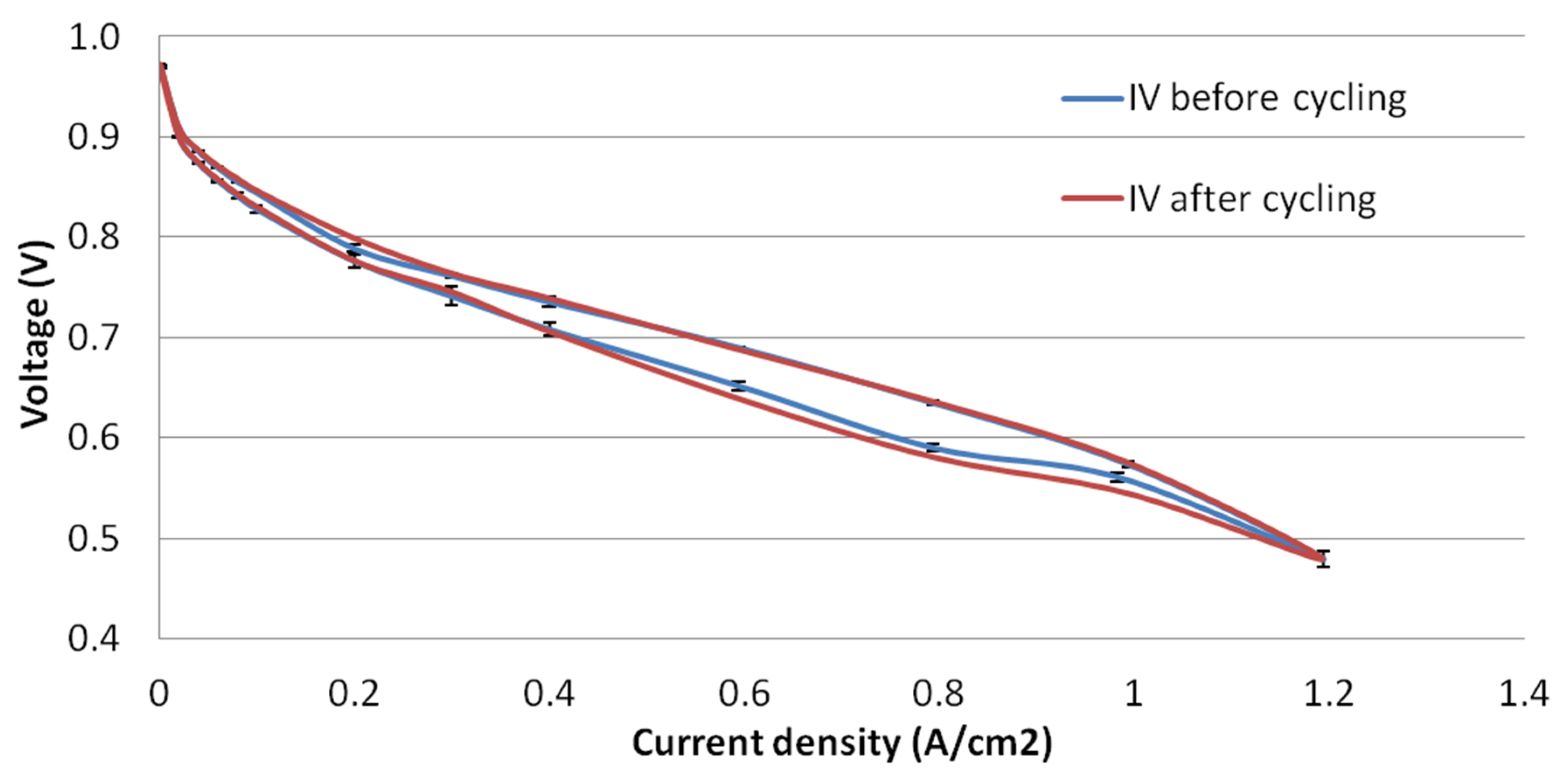
As indicated in the testing protocol [11], the polarization curves were measured both before the load cycling test and after the load cycling test. Both polarization curves are presented in Figure 9.

4. Discussion

4.1. Effect of the Operating Parameters on the Cell Performance

The results presented in Section 3 describe the performance of the fuel cell and the effect of different operating conditions. The IV curve of the reference conditions clearly features the three polarization regions (activation, ohmic, and mass transport). The hysteresis phenomenon was also remarkable in all four curves presented, where in all cases, the forward curve (increasing current) was below the backward curve (decreasing current), clearly indicating that there was a certain degree of dry-out in the cell [15,16] for all operating conditions defined. In the discussion below the polarization curve corresponding to the reference conditions was used as a benchmark for the analysis of how deviations in the operating conditions affected the performance of the cell.
The effect of increasing the cell temperature was significantly positive, as shown in Figure 4. The cell voltage increased with increasing temperature for all current densities. The main reasons are the reduction of the activation losses, as the exchange current density increased with temperature [15]. Reactant diffusion also improved with the increase in temperature. In addition, the outlet gases at higher temperature featured a higher capability to carry water out of the cell. However, operating the cell at high temperatures would also reduce the durability of the membrane [1], especially in case of poor heat management where high temperature gradients would occur.
The results of the pressure tests in Figure 5 shows a significant drop in cell performance, when operating at lower pressures (160 kPa in anode and 140 kPa in cathode, in absolute pressure). This was due to the fact that higher pressures have a positive effect in reducing the activation losses, as the exchange current density increased with pressure. In addition, water content of the membrane also increased with increase in pressure [15]. One interesting indication for this was that the slope of the polarization curve in the ohmic polarization region was steeper for the low pressure case (thus indicating a lower membrane conductivity due to a lower membrane water content). Reactant diffusion was also promoted at higher pressures. It is on the other hand noticed in Figure 5 that the case with 190/190 kPa presented a slightly better performance than the reference case with 250/230 kPa. The reason was most likely due to the enhanced cross-over effect for the case with positive pressure gradient between the anode and the cathode, adversely affecting the cell performance.
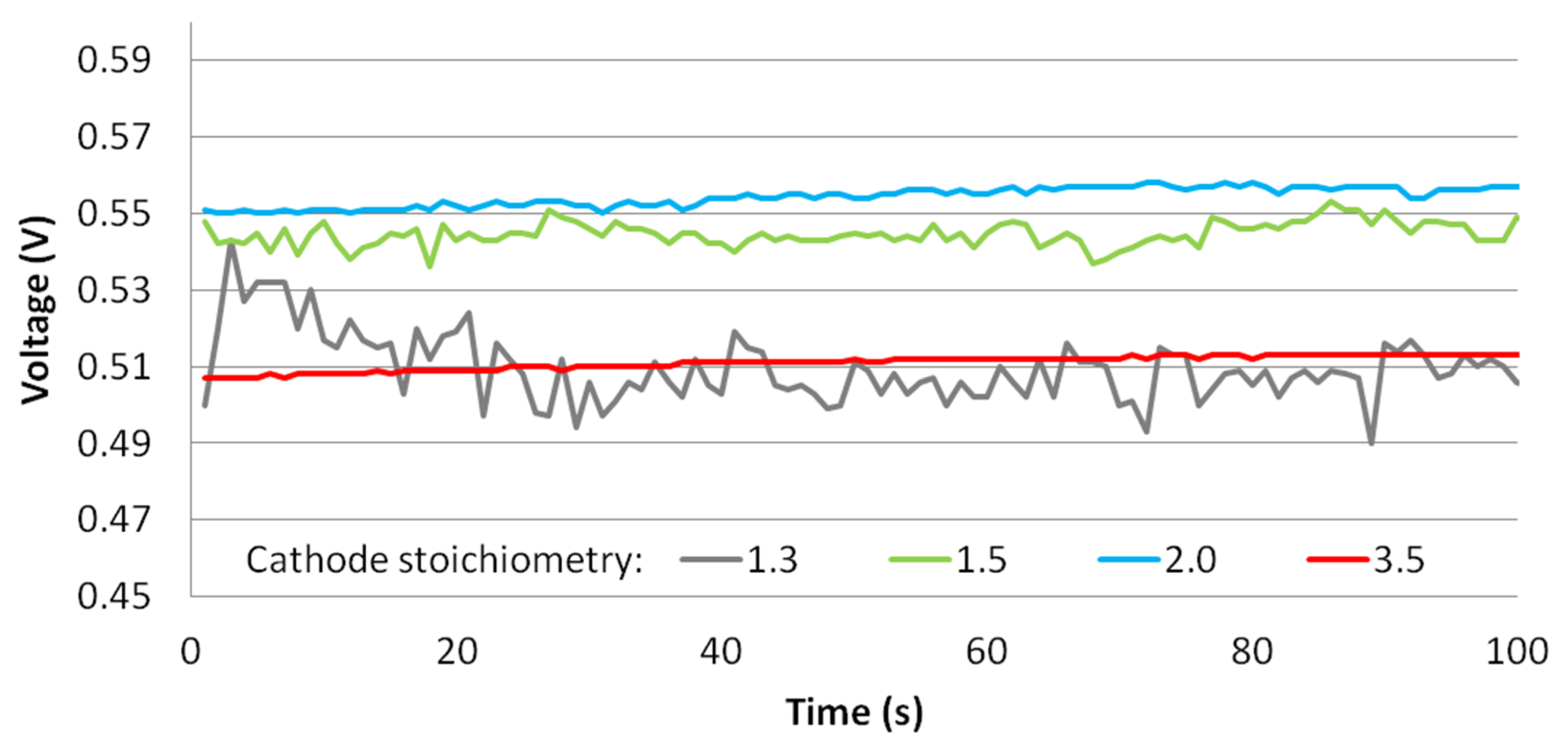
The cathode stoichiometry tests showed the importance of the cathode air flow in the final performance of the cell. In the cases analysed, a low stoichiometry λc = 1.3 presented a good performance at low current densities, but as soon as the current density increased, the cell voltage dropped dramatically, which was probably caused both by oxygen starvation at the cathode electrode and by a low liquid water removal capability in the flow-field channels. From the reference conditions of λc = 1.5, further increasing the cathode stoichiometry resulted in a lower cell performance (Figure 6), which was caused by the excessive dry-out resulting from the fact that air was supplied in relatively dry conditions (RH = 30%, Table 1) [18]. Thus, increasing the air stoichiometry promoted the drying of the cell, resulting in a lower performance. Operating at lower current air flow rates had the additional advantage of reducing parasitic losses produced by the electrical consumption of the air compressor. At the highest current density (1.2 A/cm2), the cell voltage for λc = 2.0 was, however, higher than at λc = 1.5. This was probably caused by the improved liquid water removal from the bipolar plate channels, at a higher air stoichiometry.
In addition to the overall cell performance measured in the polarization curve in Figure 6, the cell voltage stability was another aspect of interest that was influenced by the cathode stoichiometry. The time evolution of the cell voltage at 1.0 A/cm2 for all cathode stoichiometry tests is depicted in Figure 10. High oscillations in the range of 20 mV were observed for the lowest stoichiometry (λc = 1.3), which was due to the lower oxygen concentration at the cathode electrode and due to the lower liquid water removal capability from the flow-field channels. Increasing the air volume flow rate stabilized the cell voltage, where the case with λc = 3.5 presented a very stable cell voltage with oscillations <2 mV.

4.2. Load Cycling Tests

Regarding the fuel cell load cycle test, it was observed that the cell behavior was correct and it did not show any kind of voltage degradation with the number of cycles (Figure 8, top), although the number of cycles tested was obviously too low to allow for a final conclusion of the durability of the cell. At medium-high cell voltages the differences among cycles were very low (<5 mV) whereas at higher current densities and lower voltages, the differences among cycles increased up to 20 mV (Figure 8, bottom), although with no direct relationship with the cycle number. According to the results in Figure 8 there was no clear cell voltage degradation associated to the load cycling tested. Another observation was that at higher loads the cell voltage presented more oscillations, which was caused by the liquid water flooding [19,20,21]. When comparing the polarization curves before cycling and after cycling, almost the same curve was obtained, although a slight decrease in the cell voltage at high current densities was observed for the curve after cycling (less than 15 mV). This would in principle indicate a slight degradation, but it was expected to be caused by a slight decrease in the water content in the membrane in the forward curve (with increasing current) as the backward curves were exactly the same for both tests (after cycling with respect to before cycling).
The number of cycles tested did not allow to extract final conclusions on the cell degradation for a final application. Thus, a discussion is presented on the data identified in the literature. As introduced previously, degradation is a major research field in PEMFCs [1] and several accelerated stress test (ASTs) have been derived [2]. ASTs for automotive applications can be found in the literature, as in the work of Mukundan et al. [22] or Stariha et al. [23], using the U.S. DRIVE-FCTT drive cycle. In Mukundan et al., a combination of chemical/mechanical ASTs was developed, where the relative humidity was also applied to the cycles at OCV [22]. Regarding the application of the NEDC to assess fuel cell durability, it is worth mentioning the works by Han et al. [24] and Mayur et al. [25,26].
Regarding cell durability assessment with the NEDC, Han et al. analyzed the durability of a Nafion 211 25 cm2 short stack of three cells in vehicle operation, at temperatures of 55 °C and 75 °C [24], where a significantly higher degradation was observed for 75 °C. The recovery protocol detailed in [11] was also applied every 100 h. A total of 300 h of stack operation were recorded, which accounted for around 800 cycles out of the 1400 cycles defined in the original test protocol [11]. The voltage degradation rate determined was in the range 100–200 μV/h at 55 °C and 200–650 μV/h at 75 °C, after 300 h of operation (in both cases with higher values at higher current densities).
In the work of Mayur et al. [25], a multi-timescale modeling was developed, where at the cell level, a CFD (computational fluid dynamics) model was used along with a degradation model. The CFD model simulated a Nafion 112 membrane with 0.8 g Pt/cm2, operating at 250 kPa, 85 °C and 100% RH, with 1.3 and 1.5 anode and cathode stoichiometry, respectively. A total of 20,000 cycles were simulated (equivalent to 6,555 h of real drive), resulting in a degradation of 172 mV (26 μV/h). In a following work [26], the model was used to assess degradation with NEDC and also the Worldwide Harmonized Light Vehicles Test (WLTC). The Pt loading was 0.15 mg/cm2, and the operating conditions were maintained at the same levels, as in previous works of the authors. The model results showed that degradation under the NEDC load cycling was more severe than under the WLTC load cycling, mainly due to the longer exposure to idle conditions that resulted in higher Pt dissolution [26]. The end-of-life of the cell was predicted to occur after ~440 h for NEDC and ~510 for WLTC.

4.3. Cell Electrical Efficiency

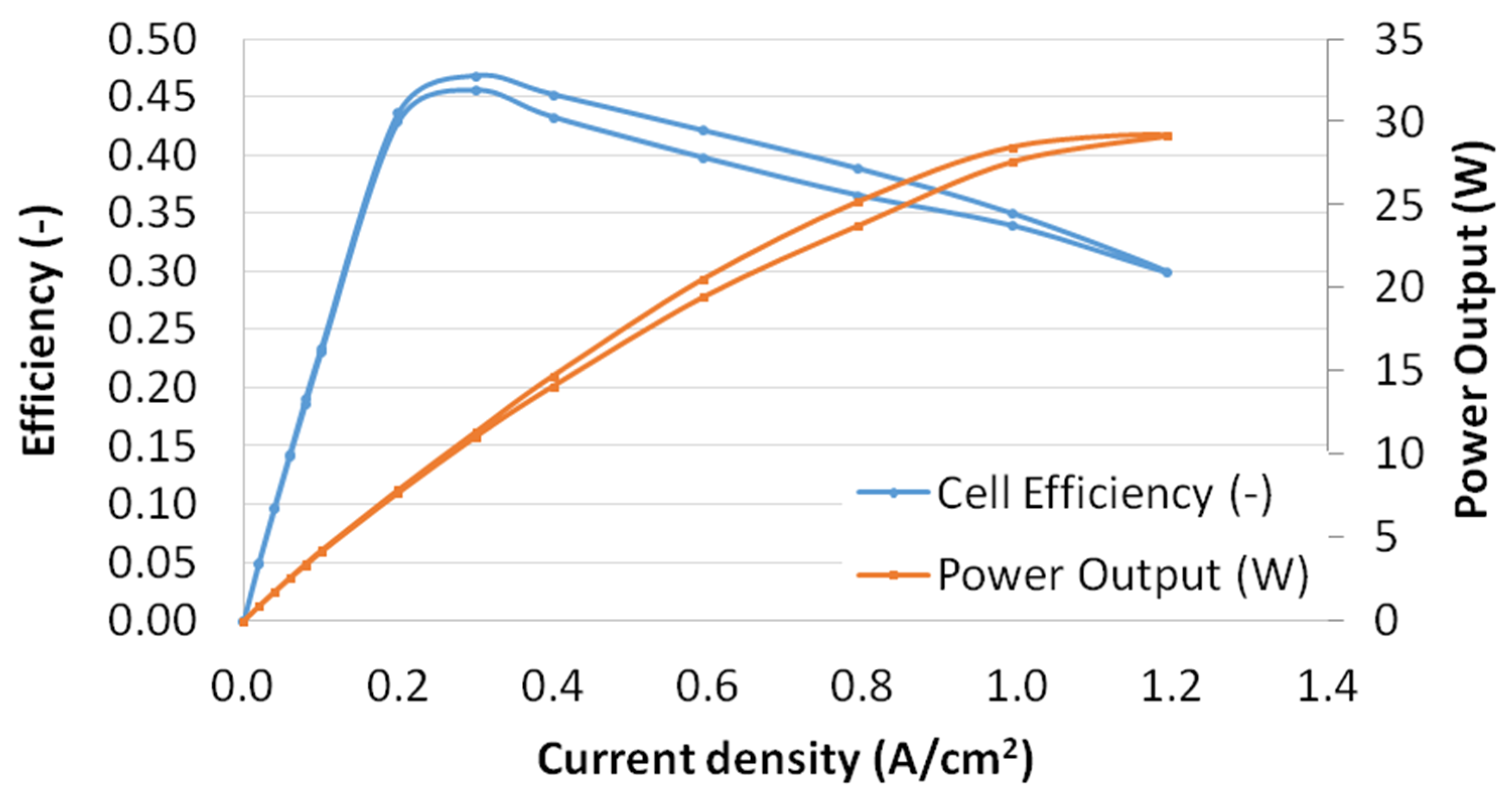
Finally, the overall cell electrical efficiency was determined for the reference conditions in Table 1. The cell efficiency was calculated as:
η = cell power output (W)/(H2 mass flow · LHVH2)
where LHVH2 is the low heating value of hydrogen. The results for the reference conditions are shown in Figure 11, together with the cell power curve.
The maximum cell efficiency was 0.46, at low current densities (0.3 A/cm2), whereas the operating condition for maximum power output occurred at 1.2 A/cm2 (with an electrical efficiency of 0.30). The anode stoichiometry was λa = 1.3, so that 30% of the hydrogen was vented, and thus the efficiency could be significantly improved by operating the cell in an anode dead-end mode. It is known that efficiencies increase for decreasing currents [15]. In Figure 11, efficiency dropped for very low currents, and this was mainly because the hydrogen mass flow controllers of the test bench operated at a minimum flow rate of 1.0 NL/min, thus, supplying a higher flow rate of hydrogen than that required for very low currents.

5. Conclusions

This work presents a contribution covering experimental studies of a 50 cm2 PEM fuel cell, including experimental results for a load cycling test. Cell performance for a comprehensive set of operating conditions, cell electrical efficiency, and cycling degradation studies were included in the experimental analysis.
The results showed that a higher temperature resulted in an increase of the cell performance. Pressure also positively enhanced the cell voltage, although a cross-over effect and a consequent performance drop seemed to appear at an anode overpressure of 20 kPa. Higher cathode stoichiometry values negatively affect the cell performance, as relatively dry air was supplied, thus, promoting the dry-out of the cell. However, a too low stoichiometry caused a sudden drop in the cell voltage at higher current densities.
No significant cell degradation was observed after the load cycling tests, although the low number of cycles carried out did not allow us to reach a final conclusion on the cell degradation for a final application.

Author Contributions

Conceptualization, A.I. and J.G.; methodology, A.I.; formal analysis, B.R.-P., A.R.-C., R.V.-G., and A.I.; investigation, A.I., B.R.-P., A.R.-C., and R.V.-G.; resources, J.G.; data curation, B.R.-P., A.R.-C., and R.V.-G.; writing—original draft preparation, A.I.; writing—review and editing, A.I.; supervision, A.I. and J.G.; project administration, A.I. and J.G.; funding acquisition, A.I. and J.G. All authors have read and agreed to the published version of the manuscript.

Funding

This research was funded by the Spanish Ministry of Science, Innovation, and Universities, grant number ENE2017-91159-EXP (bio-inspired designs for bipolar plates of PEM Fuel Cells with optimized water management) and by the Spanish Ministry of Economy and Competitiveness, grant number UNSE15-CE2962 (characterization and optimization of fuel cells for their integration in mobile and stationary applications).

Acknowledgments

The authors kindly acknowledge Pablo Iranzo Pineda for the preparation and editing of Figure 1 and Figure 2.

Conflicts of Interest

The authors declare no conflict of interest.

Appendix A

The polarization curve set points for the forward and backward curves defined for the experiments according to [11] is presented in Table A1.
Table A1. Polarization curve set points (forward and backward curves) based on [11].
Set Point ID Current Density (A/cm2)Dwell Time (s)Data Acquisition Time (s)
10.006030
20.026030
30.046030
40.066030
50.086030
60.106030
70.2020030
80.3020030
90.4020030
100.6020030
110.8020030
121.0020030
131.2020030
141.0020030
150.8020030
160.6020030
170.4020030
180.3020030
190.2020030
200.106030
210.086030
220.066030
230.046030
240.026030
250.006030

Appendix B

The complete test as defined in [12] consists of repeating the specified load cycles to the cell for 500 h (1400 cycles), which would correspond to a one year utilization of the vehicle, and 80 daily minutes. The cycle comprises periods of acceleration, deceleration, and constant speed.
Each test must start defining the desired operating conditions and performing the required conditioning step [11]. After this, the cell performance at the Beginning of Test (BoT) is evaluated by measuring a polarization curve (according to the set points indicated in Appendix A). The load cycles defined in Table A2 are then carried out. The protocol states 50 consecutive cycles (5 cycles were carried out in this work, as the test was intended for laboratory-scale tests). After the first load cycling block, a new polarization curve must be measured and compared to the one recorded at BoT, in order to measure the degradation rate (µV/h). The 50 cycling steps and polarization curve recordings are repeated until the 1400 driving cycles are completed [11].
The dynamic load cycling test set points defined for the experiment according to [11] are presented in Table A2.
Table A2. Fuel cell dynamic load cycle set points, based on [11].
StepTime (s)Dwell (s)Load (%)
10150.0
2151312.5
328335.0
4613526.7
596475.0
61432041.7
71632529.2
8188225.0
92101312.5
10223335.0
112563526.7
12291475.0
133382041.7
143582529.2
15383225.0
164051312.5
17418335.0
184513526.7
19486475.0
205332041.7
215532529.2
22578225.0
236001312.5
24613335.0
256463526.7
26681475.0
277282041.7
287482529.2
29773685.0
308415858.3
318998241.7
329818558.3
3310665083.3
34111644100
351160210.0
According to protocol [11], the 100% load value was obtained by averaging the two current values (forward and backward curves) corresponding to 0.65 V. This was done (Figure A1) with a result of 0.675 A/cm2 (corresponding to 33.75 A).
Figure A1. Method for identifying the 100% load in a polarization curve, as described in [11]. The 100% load value is obtained by averaging the two current values (in red) corresponding to the forward and backward curves (in blue) at 0.65 V.
Processes 08 00608 g0a1

Appendix C

The raw experimental data of this work is available in the journal Data, Ramírez-Cruzado et al. [27].

Appendix D

The time evolution of the cell voltage during the conditioning step is depicted in Figure A2, showing the +/−5 mV criteria, according to [11].
Figure A2. Evolution of the cell voltage during the cell conditioning step. The +/−5 mV range is marked in red.
Processes 08 00608 g0a2

References

  1. Wu, J.; Yuan, X.Z.; Martin, J.J.; Wang, H.; Zhang, J.; Shen, J.; Wu, S.; Merida, W. A review of PEM fuel cell durability: Degradation mechanisms and mitigation strategies. J. Power Sources 2008, 184, 104–119. [Google Scholar] [CrossRef]
  2. Zhang, S.; Yuan, X.; Wang, H.; Mérida, W.; Zhu, H.; Shen, J.; Wu, S.; Zhang, J. A review of accelerated stress tests of MEA durability in PEM fuel cells. Int. J. Hydrog. Energy 2009, 34, 388–404. [Google Scholar] [CrossRef]
  3. Iranzo, A.; Muñoz, M.; López, E.; Pino, J.; Rosa, F. Experimental fuel cell performance analysis under different operating conditions and bipolar plate designs. Int. J. Hydrog. Energy 2010, 35, 11437–11447. [Google Scholar] [CrossRef]
  4. Salva, J.A.; Iranzo, A.; Rosa, F.; Tapia, E.; Lopez, E.; Isorna, F. Optimization of a PEM fuel cell operating conditions: Obtaining the maximum performance polarization curve. Int. J. Hydrog. Energy 2016, 41, 19713–19723. [Google Scholar] [CrossRef]
  5. Wu, J.; Yuan, X.Z.; Wang, H.; Blanco, M.; Martin, J.J.; Zhang, J. Diagnostic tools in PEM fuel cell research: Part I Electrochemical techniques. Int. J. Hydrog. Energy 2008, 33, 1735–1746. [Google Scholar] [CrossRef]
  6. Salva, J.A.; Iranzo, A.; Rosa, F.; Tapia, E. Experimental validation of the polarization curve and the temperature distribution in a PEMFC stack using a one dimensional analytical model. Int. J. Hydrog. Energy 2016, 41, 20615–20632. [Google Scholar] [CrossRef]
  7. Zhang, G.; Jiao, K. Multi-phase models for water and thermal management of proton exchange membrane fuel cell: A review. J. Power Sources 2018, 39, 120–133. [Google Scholar] [CrossRef]
  8. Iranzo, A.; Muñoz, M.; Rosa, F.; Pino, J. Numerical model for the performance prediction of a PEM fuel cell. Model results and experimental validation. Int. J. Hydrog. Energy 2010, 35, 11533–11550. [Google Scholar] [CrossRef]
  9. Iranzo, A.; Boillat, P.; Biesdorf, J.; Salva, J. Investigation of the liquid water distributions in a 50 cm2 PEM fuel cell: Effects of reactants relative humidity, current density, and cathode stoichiometry. Energy 2015, 82, 914–921. [Google Scholar] [CrossRef]
  10. Bloom, I.; Walker, L.K.; Basco, J.K.; Malkow, T.; Saturnio, A.; De Marco, G.; Tsotridis, G. A comparison of Fuel Cell Testing protocols—A case study: Protocols used by the U.S. Department of Energy, European Union, International Electrotechnical Commission/Fuel Cell Testing and Standardization Network, and Fuel Cell Technical Team. J. Power Sources 2013, 243, 451–457. [Google Scholar] [CrossRef]
  11. Tsotridis, G.; Pilenga, A.; De Marco, G.; Malkow, T. EU Harmonised Test Protocols for PEMFC MEA Testing in Single Cell Configuration for Automotive Applications; Publications Office of the European Union: Luxembourg, 2015; ISBN: 978-92-79-54133-9 (print), 978-92-79-54132-2 (PDF). [Google Scholar] [CrossRef]
  12. “Agreement Concerning the Adoption of Uniform Technical Prescriptions for Wheeled Vehicles, Equipment and Parts Which Can Be fitted and/or Be Used on Wheeled Vehicles and the Conditions for Reciprocal Recognition of Approvals Granted on the Basis of These Prescriptions”, Addendum 100: Regulation no. 101, Uniform Provisions Concerning the Approval of Passenger Cars Powered by an Internal Combustion Engine Only, or Powered by a Hybrid Electric Power Train with Regard to the Measurement of the Emission of Carbon Dioxide and Fuel Consumption and/or the Measurement of Electric Energy Consumption and Electric Range, and of Categories m1 and n1 Vehicles Powered by an Electric Power Train only with Regard to the Measurement of Electric Energy Consumption and Electric Range; E/ECE/324/Rev.2/Add.100/Rev.3 or E/ECE/TRANS/505/Rev.2/Add.100/Rev.3 (12 April 2013); United Nations: Geneva, Switzerland, 2013.
  13. Huicui, C.; Zhen, S.; Xin, Z.; Tong, Z.; Pucheng, P.; Chen, L. A review of durability test protocols of the proton exchange membrane fuel cells for vehicle. Appl. Energy 2018, 224, 289–299. [Google Scholar]
  14. Zhao, J.; Li, X. A review of polymer electrolyte membrane fuel cell durability for vehicular applications: Degradation modes and experimental techniques. Energy Convers. Manag. 2019, 199, 112022. [Google Scholar] [CrossRef]
  15. Barbir, F. PEM Fuel Cells: Theory and Practice, 2nd ed.; Academic Press: Amsterdam, The Netherlands, 2013; ISBN 978-0-12-387710-9. [Google Scholar] [CrossRef]
  16. Hou, J. A study on polarization hysteresis in PEM fuel cells by galvanostatic step sweep. Int. J. Hydrog. Energy 2011, 36, 7199–7206. [Google Scholar] [CrossRef]
  17. DOE Technical Targets for Polymer Electrolyte Membrane Fuel Cell Components. Available online: https://www.energy.gov/eere/fuelcells/doe-technical-targets-polymer-electrolyte-membrane-fuel-cell-components (accessed on 12 April 2020).
  18. Weng, F.B.; Su, A.; Hsu, C.Y. The study of the effect of gas stoichiometric flow rate on the channel flooding and performance in a transparent fuel cell. Int. J. Hydrog. Energyy 2007, 32, 666–676. [Google Scholar] [CrossRef]
  19. Iranzo, A.; Salva, A.; Boillat, P.; Biesdorf, J.; Tapia, E.; Rosa, F. Water build-up and evolution during the start-up of a PEMFC: Visualization by means of Neutron Imaging. Int. J. Hydrog. Energy 2017, 42, 13839–13849. [Google Scholar] [CrossRef]
  20. Lin, R.; Cao, C.; Ma, J.; Gülzow, E.; Friedrich, K.A. Optimizing the relative humidity to improve the stability of a proton exchange membrane by segmented fuel cell technology. Int. J. Hydrog. Energyy 2012, 37, 3373–3381. [Google Scholar] [CrossRef]
  21. Iranzo, A.; Gregorio, J.M.; Boillat, P.; Rosa, F. Bipolar plate research using Computational Fluid Dynamics and neutron radiography for proton exchange membrane fuel cells. Int. J. Hydrog. Energy 2020, 45, 12432–12442. [Google Scholar] [CrossRef]
  22. Mukundan, R.; Baker, A.M.; Kusoglu, A.; Beattie, P.; Knights, S.; Weber, A.Z.; Borup, R.L. Membrane Accelerated Stress Test Development for Polymer Electrolyte Fuel Cell Durability Validated Using Field and Drive Cycle Testing. J. Electrochem. Soc. 2018, 165, F3085–F3093. [Google Scholar] [CrossRef]
  23. Stariha, S.; Macauley, N.; Sneed, B.T.; Langlois, D.; More, K.L.; Mukundan, R.; Borup, R.L. Recent Advances in Catalyst Accelerated Stress Tests for Polymer Electrolyte Membrane Fuel Cells. J. Electrochem. Soc. 2018, 165, F492–F501. [Google Scholar] [CrossRef]
  24. Han, J.; Han, J.; Yu, S.; Rosa, F. Experimental analysis of performance degradation of 3-cell PEMFC stack under dynamic load cycle. Int. J. Hydrog. Energy 2020, 45, 13045–13054. [Google Scholar] [CrossRef]
  25. Mayur, M.; Gerard, M.; Schott, P.; Bessler, W.G. A multi-timescale modeling methodology for PEMFC performance and durability in a virtual fuel cell car. Int. J. Hydrog. Energy 2015, 40, 16466–16476. [Google Scholar] [CrossRef] [Green Version]
  26. Mayur, M.; Gerard, M.; Schott, P.; Bessler, W.G. Lifetime prediction of a polymer electrolyte membrane fuel cell under automotive load cycling using a physically-based catalyst degradation model. Energies 2018, 11, 2054. [Google Scholar] [CrossRef] [Green Version]
  27. Ramírez-Cruzado, A.; Ramírez-Peña, B.; Vélez-García, R.; Iranzo, A.; Guerra, J. Data for Experimental analysis of the performance and load cycling of a Polymer Electrolyte Membrane Fuel Cell. Data 2020, 5, 47. [Google Scholar] [CrossRef]
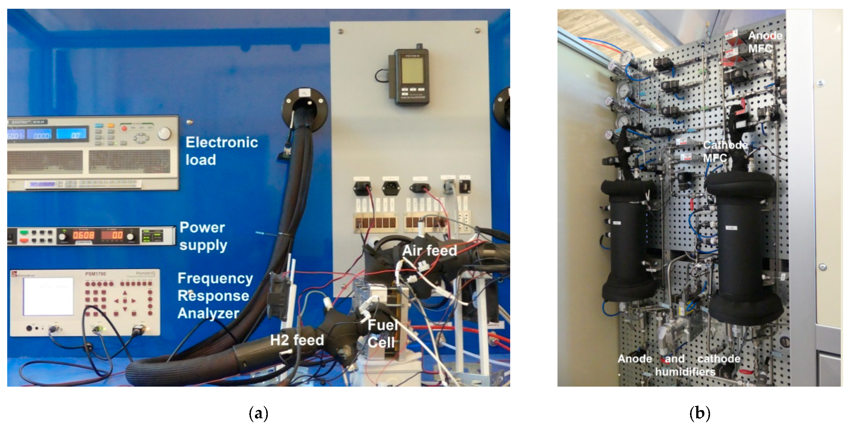
Figure 1. Test bench (a) front view showing the main components; and (b) back view showing the BoP (Balance of Plant).
Processes 08 00608 g001
Figure 2. (Top) Graphite bipolar plates (anode side and cathode side) with serpentine flow field. (Bottom left) External fan (black) and film heater attached to the terminal plates for temperature control. (Bottom right) Thermocouple inserted into the cathode monopolar plate for cell temperature measurement.
Processes 08 00608 g002
Figure 3. Polarization curve for reference conditions. Forward curve (increasing current) in the bottom; Backward curve (decreasing current) at the top. Error bars corresponding to three repetitions are included for each measurement point.
Processes 08 00608 g003
Figure 4. Polarization curve for temperature tests. Forward curve (increasing current) at the bottom; backward curve (decreasing current) at the top. Error bars corresponding to the three repetitions are included for each measurement point.
Processes 08 00608 g004
Figure 5. Polarization curve for pressure tests. Forward curve (increasing current) at the bottom; backward curve (decreasing current) at the top. Error bars corresponding to the three repetitions are included for each measurement point.
Processes 08 00608 g005
Figure 6. Polarization curve for cathode stoichiometry tests (λc = 1.3, 1.5, 2.0, 3.5). λc = 1.5 corresponds to the reference conditions. Forward curve (increasing current) at the bottom; backward curve (decreasing current) at the top. Error bars corresponding to the three repetitions are included for each measurement point.
Processes 08 00608 g006
Figure 7. Evolution of cell voltage (in blue) during the load cycle test. Current density profile defined according to Appendix B is shown in red.
Processes 08 00608 g007
Figure 8. Superposition of the evolution of the cell voltage corresponding to the five cycles during the load cycle test. (Top) complete load cycles; (Bottom) high load (15 min to 21 min) close-up.
Processes 08 00608 g008
Figure 9. Polarization curves recorded before load cycling and after load cycling. Error bars corresponding to three repetitions are included for each measurement point.
Processes 08 00608 g009
Figure 10. Time evolution of the cell voltage for the cathode stoichiometry tests at 1.0 A/cm2.
Processes 08 00608 g010
Figure 11. Cell efficiency curve and power curve for reference conditions (Table 1); λa = 1.3.
Processes 08 00608 g011
Table 1. Operating conditions defined for the fuel cell (according to the testing protocol [11]).
Operating
Condition
Reference
Conditions
Test
Temperature
Test
Pressure
Test Cathode Stoichiometry
Cell Temperature (°C)8070, 858080
Anode Pressure (kPa) 1250250160; 190250
Cathode Pressure (kPa) 1230230140; 190230
Anode RH (%)50505050
Cathode RH (%)30303030
Anode Stoichiometry (-)1.31.31.31.3
Cathode Stoichiometry (-)1.51.51.51.3, 2.0, 3.5
1 Absolute pressure.