Article

Non-Linear Sliding Mode Controller for Photovoltaic Panels with Maximum Power Point Tracking

by
Hina Gohar Ali
1,2,*,
Ramon Vilanova Arbos
1,
Jorge Herrera
3,
Andrés Tobón
4 and
Julián Peláez-Restrepo
4
1
Departament de Telecomunicació i d’Enginyeria de Sistemes, Escola d’Enginyeria Universitat Autònoma de Barcelona (UAB), Bellaterra, Cerdanyola del Vallés, 08193 Barcelona, Spain
2
School of Electrical Engineering and Computer Science, National University of Sciences and Technology (NUST), Islamabad 44000, Pakistan
3
Departamento de Ingeniería, Facultad de Ciencias Naturales e Ingeniería, Universidad de Bogotá Jorge Tadeo Lozano, Bogotá, Distrito Capital 110311, Colombia
4
Departamento de Electrónica y Telecomunicaciones, Facultad de Ingenierías, Instituto Tecnológico Metropolitano, Calle 54 A #30-01, Medellín, Antioquia, Colombia
*
Author to whom correspondence should be addressed.
Processes 2020, 8(1), 108; https://doi.org/10.3390/pr8010108
Submission received: 11 November 2019 / Revised: 20 December 2019 / Accepted: 8 January 2020 / Published: 14 January 2020
(This article belongs to the Section Process Control and Monitoring)

Abstract

:
In this paper, nonlinear sliding mode control (SMC) techniques formulated for extracting maximum power from a solar photovoltaic (PV) system under variable environmental conditions employing the perturb and observe (P and O) maximum power point tracking (MPPT) technique are discussed. The PV system is connected with load through the boost converter. A mathematical model of the boost converter is derived first, and based on the derived model, a SMC is formulated to control the gating pulses of the boost converter switch. The closed loop system stability is verified through the Lyapunov stability theorem. The presented control scheme along with the solar PV system is simulated in MATLAB (matric laboratory) (SMC controller and PWM (Pulse Width Modulation) part) and PSIM (Power electronics simulations) (solar PV and MPPT algorithm) environments using the Simcoupler tool. The simulation results of the proposed controller (SMC) are compared with the classical proportional integral derivative (PID) control scheme, keeping system parameters and environmental parameters the same.

1. Introduction

The current global energy demand of the world has been continuously tremendously increasing due to various reasons, such as population growth, general economic growth, and industrial growth. The majority of energy needs have been fulfilled over the centuries by fossil fuels.
Major concerns associated with fossil fuels are ever-increasing prices and adverse effects on nature, which results in a global energy crisis due to limited supply. These fuels cannot be renewed at the rate of their consumption, so these are termed as non-renewable energy sources [1]. A solution to these issues is to use renewable energy sources which are inexhaustible and cause less pollution when compared to fossil fuels.
There are different sources of renewable energy, such as solar energy, wind energy, biomass energy, ocean energy, geothermal energy, hydropower, and biofuel [2], among others.
Some other energy adequacy has been discussed in detail in Reference [3]. Among several renewable energy resources, solar energy is one of the most sustainable energy sources [4] because of the fact that it is clean, inexhaustible, free, and has a long-life expectancy. The energy which is consumed on earth is almost ten thousand times less than the sun energy imparted upon us. Therefore, it is necessary to develop instruments which will utilize the unrestricted energy sources by using a photovoltaic (PV) system.
PV panels are devices that convert sunlight directly into electricity by exploiting a photoelectric effect. It is a group of solar cells, which is the basic unit of the solar system. Stand-alone systems and grid-connected systems are the two main classifications of photovoltaic systems. Stand-alone PV systems operate independently from the utility grid [5] and are generally designed for supplying DC or AC electrical loads. For example, in Reference [6], the design of a stand-alone photovoltaic system for footbridge lighting has been analyzed for the AC loads. On the other hand, grid-connected systems are connected to the utility grid [7] which is composed of grid-connected equipment, a power conditioning unit, an inverter, and a PV array.
The PV system has exhibited a nonlinear current-voltage (I-V) and power-voltage (P-V) characteristics which vary with the solar irradiance and temperature of the cell. Efficiency becomes low in PV due to the energy transformation from electrical to solar, which causes the main obstacles in the maximum solar energy utilization. Consequently, it is of great importance to obtain the maximum efficiency of PV systems. This is achieved by making an optimal follow-up of the maximum power point (MPP), which means keeping the system working at the operation point where the extraction of power is maximum. Therefore, maximum power point tracking (MPPT) techniques are introduced to extract maximum power from PV panels to significantly use the PV panel power [8,9].
Numerous algorithms have been proposed in the literature to accomplish the goal of MPPT [10] and can be distinguished from one another based on different features, such as complexity, convergence speed, implementation, effectiveness range, and various other aspects [11]. The perturb and observe (P and O) technique is the most used due to its ease of implementation and low cost [12]. In P and O, the perturbation is made in the operating point until maximum power is achieved.
It operates by periodically perturbing the control variable and comparing the instantaneous PV powers before and after the perturbation. This algorithm is composed of two critical parameters: the sampling interval (Ta), in which the algorithm perturbs the control variable, and the amplitude of such perturbation (ΔVref). Due to its simple implementation, the P and O is adopted to generate reference voltage (ΔVref) [13,14].
Numerous linear controllers can also be used along with different algorithms for MPPT, which guarantee a proper tracking of the reference voltage generated by the MPPT algorithm to mitigate the perturbations [15]. The main problem associated with these kinds of controllers is that they are based on a linearized model of the PV system around a given operating point, which does not ensure the same performances in all of the PV operation range. Other types of controllers have been proposed in the literature to ensure a correct behavior of the system without requiring a linearization process [16]. Some of those controllers are based on adaptive laws [17] and energy balance [18].
Due to the nonlinear feature of PV arrays and power converters, applying non-linear controllers presents a good solution. A non-linear backstepping and integral backstepping controller is proposed in References [19,20] to track the MPP of PV. In Reference [21], a non-linear, robust integral backstepping-based MPPT control scheme is proposed for MPP tracking of the PV array.
The sliding mode controller (SMC) is a non-linear control strategy derived from variable structure system (VSS) theory, which was originally introduced in References [22,23]. The switched-mode (DC-DC) converters used in PV system applications are the ideal target of this kind of controller. In SMC, the control scheme is designed to drive and then retain the system states within the limits of the switching function. This approach offers two main advantages. First, the dynamic behavior of the system may be tailored by the specific choice of switching function. Secondly, the closed-loop system response becomes insensitive to a particular class of uncertainty. This property makes the SMC a proper candidate for robust control. In addition, the ability to specify performance directly makes sliding mode control attractive from a design perspective. The classical SMC consists of two components. The first component comprises the design of a switching function, so that the sliding motion achieves the design specifications. The second component is associated with the selection of a control law that will make the switching function attractive to the system state [24]. This is not always true for a control law to be discontinuous in nature. The most eminent feature of SMC is that it is completely insensitive to parametric uncertainty and external disturbances during the sliding mode. In particular, the sliding mode approach offers stability and robustness against parameters, input, and load uncertainties, which are common in PV systems. Moreover, SMC is simpler to implement in comparison with other types of nonlinear controllers [25]. The sliding mode control has received much attention because of its benefits of a quick response and robustness.
In this article, an integer order SMC is proposed for the extraction of maximum power from a PV panel under varying radiation and temperature. This is to highlight that the proposed system is controlled by the sliding mode controller formulated in References [16,23], i.e., a design of stable SMC to track the reference provided by the P and O MPPT algorithm. The overall system consists of a PV panel connected to a boost converter, which in turns supplies power to a DC load. The P and O MPPT algorithm is employed to generate the reference PV voltage with a boost converter for the SMC controller. The SMC controller is derived based on the nonlinear mathematical model of a PV panel with a boost converter. A classical integer order sliding surface is chosen and then control law is derived, such that the overall closed loop system should strictly track the reference voltage generated through the MPPT algorithm and the response should remain insensitive to parametric variations. The stability of the proposed SMC is proved by selecting the integer order Lyapunov candidate function. PV, along with the boost converter and MPPT algorithm, is modeled in PSIM, whereas the SMC controller is implemented in MATLAB/Simulink. The SMC controller is coupled through the Simcoupler interface between PSIM and MATLAB/Simulink. In order to test the superiority of the proposed controller, the simulation results are compared with the classical proportional integral derivative (PID) controller.
The overall paper is structured as follows: In Section 2, related work is discussed. Section 3 introduces the system model used in this work and the proposed control scheme is defined. Simulation results are presented in Section 4. Finally, Section 5 summarizes the conclusions and future work.

2. Related Work/Background

Figure 1 presents a typical control structure for the PV system aimed at regulating the PV voltage to a reference given by the MPPT algorithm and to mitigate the oscillations in the environmental conditions. The PID controller is designed from the linearization of the PV system around a specific operating point, e.g., the MPP at the lowest irradiance for a stand-alone system, as in Reference [13]. Therefore, to guarantee the same performance in all of the operation range, it is necessary to design non-linear controllers that do not depend on linearized models.
Sliding mode control (SMC) has been proposed in the literature to ensure correct behavior without the need of linearization. This work is based on the ideas published in References [26,27,28], which apply the sliding mode technique to regulate the PV voltage and to mitigate the oscillations. The proposed scheme implemented in this work is presented in Figure 2. In this implementation, the voltage and current of the PV array are provided to a P and O algorithm, which defines the reference to the SMC controller to provide reference peak power voltage, which can be tracked by the proposed non-linear controller. The controller has been derived using the mathematical model of a non-inverting boost converter and generates an output signal µ, which controls the duty ratio of the PWM signal provided to the converter switches.
The MPPT-based P and O generates the reference voltage Vref, which is compared with panel voltage VPV to generate an error signal, which is supplied to the improved sliding mode controller. The controller generates the control input µ, which controls the PWM signal width and drives the converter to track the reference voltage. Hence, operating the PV module on this reference voltage will ensure that maximum power is generated by the system.

3. System Modeling

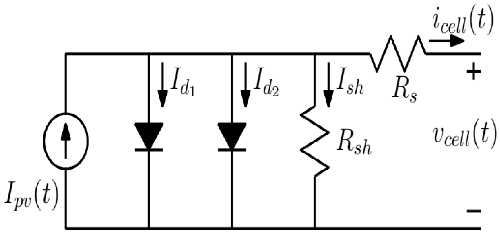
3.1. Photovoltaic (PV) Model
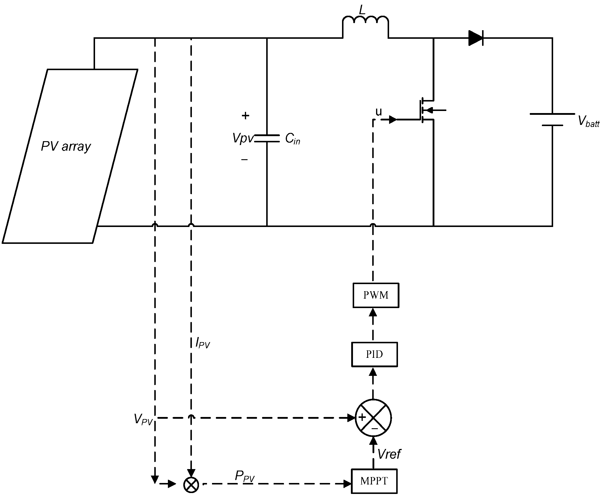
Mathematical models are used to describe the operation and behavior of the PV panels in the calculation of the current-voltage characteristic. The current voltage (I-V relation) mathematical equation of the solar cell is implicit and non-linear. For precise PV cell modeling and better accuracy, in this work, we use a two diode PV model which involves identification of more parameters at the expense of longer computational time and is known as being a seven-parameter model [29]. Simulations are based on the double-diode model, since their estimation is more useful with other models (i.e., single diode model) [30]. The PV panel based on the two diode model is shown in Figure 3.
To operate the PV panel at MPP, a DC-DC converter controlled by the MPPT is inserted between the PV panel and the load. DC-DC converters are used widely for the efficient management of energy in PV systems. The boost converter has been chosen for this work [31], as shown in Figure 2.
To extract the maximum possible power of the panel, the P and O algorithm is implemented, which is the most widely used MPP tracking method. P and O generates the reference voltage Vref after measurement of the panel power. If the measured power is greater than the previous power, the reference voltage is steadily incremented in the same proportion, otherwise, if not, then it is decreased. Figure 4 presents the P and O algorithm flow diagram, which is implemented with PSIM simulation tools. This method finds the maximum power point (MPP) of PV modules by iteratively perturbing the reference voltage and observing and comparing the power generated by the PV module at any instant with the previous power. The voltage perturbation is achieved through the change in reference voltage, ΔVref. The increment or decrement of the reference voltage in every sampling period is determined by the comparison of the power at the present time and previous time. The sign of the error, ΔP(k) = P(k) − P(k − 1), is used to determine the direction of perturbation. If the incremental power, ΔP(k) > 0, the duty cycle should be increased in order to make ΔVref > 0. On the other hand, if ΔP(k) < 0, then the reference voltage is reduced to make ΔVref < 0.

3.2. Control Scheme

3.2.1. DC-DC Converter Model

Power electronic converters (DC-DC) are used in photovoltaic systems as an adaptation stage between the PV panel and the load. The DC-DC power converter is connected to adjust the PV panel output voltage to maximize the solar power generation. In this work, we adapt a boost converter which steps up voltage from its input (PV array) to its output (load), in order to operate the PV panel at the MPP. It is assumed that the converter is operating in continuous conduction mode.
The converter is used to regulate the PV module output voltage, VPV, in order to extract as much power as possible from the PV module. Referring to Reference [28], the dynamics of the boost converter is given by:
I c i n = C i n d V p v d t = I p v I L
V L = L d I L d t = V P V V b ( 1 u )
where Icin, PV, Vb, Cin, VL, L, and L represent capacitor current, PV current, battery voltage, input capacitor capacitance, voltage across inductor, inductor current, and inductor inductance, respectively.
Rearranging Equations (1) and (2), we have:
V ˙ P V = I L C i n + I P V C i n
I ˙ L = V P V L V b L + V b L u
Equations (3) and (4) can be written in state space form as:
[ V ˙ P V I ˙ L ] = [ 0 1 C i n 1 L 0 ] [ V P V I L ] + [ I P V C i n 0 V b L 0 ] [ 1 0 ] + [ 0 V b L ] u
Equation (5) can be re-written in generalized form as:
X ˙ = f ( X , t ) + J ( X , t ) + h ( X , t ) u
Here, X = [ x 1 x 2 ] T = [ V P V I L ] T represents PV panel voltage and inductor current, J(X, t) and h(X, t) represent nominal system inputs, and u represents the control excitation.
f ( X , t ) = [ 0 1 C i n 1 L 0 ]
J ( X , t ) = [ I P V C i n 0 V b L 0 ]
h ( X , t ) = [ 0 V b L ]

3.2.2. Controller Formulation

The objective of the closed loop control system is that panel voltage, *VPV, must strictly follow the VPV-ref generated by the MPPT algorithm so that maximum power can be extracted from the PV panel under varying sunlight and temperature.
The reference signal generated by the MPPT algorithm can be written as:
X d = [ x d x ˙ d ] T = [ V P V r e f V ˙ P V r e f ] T
The tracking error can be defined as:
{ e 1 = x 1 x d e 2 = e ˙ 1 e 2 = x 2 x ˙ d e ˙ 2 = x ˙ 2 x ¨ d }
Sliding surface is chosen as:
s = k 1 e 1 + e 2
Here, k1 > 0 is the design parameter. Differentiating Equation (12), on both sides:
s ˙ = k 1 e 2 + e ˙ 2
By combining Equations (6) and (13) one can obtain:
s ˙ = c 1 e 2 + f ( X , t ) + J ( X , t ) + h ( X , t ) u x ¨ d
To derive the control set s ˙ = 0 , the desired response can be achieved by choosing the control law as:
{ u = u e q + u s u e q = h ( X , t ) 1 [ x ¨ d f ( X , t ) J ( X , t ) c 1 e 2 ] u s = h ( X , t ) 1 k s sgn ( s )
where u e q is the equivalent control item to drive the nominal part of the system, u s is the robust switching control term, and k s is switching gain, and sgn ( . ) is the signum function, defined as:
sgn ( s ) = { + 1 i f s > 0 0 i f s = 0 1 i f s < 0

3.2.3. Stability Proof of the Proposed Controller

The stability of the proposed control scheme can be proved by choosing the Lyapunov candidate function as:
V = 1 2 S 2
where ‘S’ represents the sliding surface chosen in Equation (12). According to Lyapunov, the control system will be stable if the derivative of the Lyapunov candidate is negative along the closed-loop system trajectories.
Thus, by taking the derivative of Equation (17), we get:
V ˙ = S S ˙
Putting ‘S’ from Equation (14) into Equation (18), we get:
V ˙ = S ( c 1 e 2 + f ( X , t ) + J ( X , t ) + h ( X , t ) u x ¨ d )
Putting the value of ‘u’ from Equation (15) into Equation (19) and simplifying, we obtain:
V ˙ = S ( k s sgn ( S ) ) ( k s | S | ) 0
It can be shown that V ˙ 0 if the switching gain ks > 0 and the closed loop system is stable.

4. Simulation Results

Matlab/Simulink is used to model and simulate the proposed controller’s technique. While the PV panel along with the boost converter and MPPT algorithm simulations are performed in PSIM (PowerSim), Simcoupler is used as an interface to couple Simulink and PSIM co-simulation.
The parameters of the PV array that are used in this work are mentioned in Table 1. From Table 1, the short circuit current, open circuit voltage, and maximum power point tracking voltage of a single PV panel is given, for which a single DC-DC boost converter is selected. The parameters of the input capacitor and the inductor are selected such that the inductor current ripple equals to 1. A physical model of a PV panel is used according to the renewable energy module of PSIM [32], with parameters corresponding to the PV module of type MSX-60 [33].
Similarly, the parameters of the controller and converter are arranged in Table 2. The design parameters of controllers are selected using Matlab optimization tools which are given in this Table.
Simulations of the proposed controller are performed in PSIM and MATLAB/Simulink to verify its performance. The system is perturbed with an irradiance step of 1000 W/m2 in the instant 0 and after 50 ms, the irradiance is decreased by 50%. The irradiance is varied to validate the robustness of the proposed MPPT technique and temperature is kept constant at 25 °C. The relationship coefficient of the Solar Panel MSX-60 used in the paper is ±0.05 °C m2/W. This means that for an environment temperature of 25 °C, the PV panel will operate up to 40 °C if irradiance is 1000 W/m2, and 32.5 °C if irradiance is 500 W/m2. Similarly, the temperature coefficient of power is −(0.5 ± 0.15)%/°C, which implies that maximum output power will be reduced to half if the irradiance level varies from maximum to half. The same effect is simulated in the paper, and the irradiance level has been instantly reduced to 50% after 50 ms.

4.1. Response Using the Proportional Integral Derivative (PID) Controller

To show the performance of the proposed SMC controller, it is compared with a conventional PID controller. The conventional controller response based on the P and O MPPT algorithm can be seen in Figure 5a–c, with a P and O perturbation amplitude of 1 V. The voltage tracking of the conventional controller is shown in Figure 5a. Reference ‘Vref’ of the peak power voltage generated by P and O MPPT is successfully tracked by the PID controller. ‘VPV’ reaches the desired set point ‘Vref’ in a settling time of 5 ms. Figure 5b shows the tracking error of the conventional controller with high ripples and oscillation. PV array output power along with the reference power curve is shown in Figure 5c. It can be observed that MPP is achieved by the conventional PID controller within 5 ms; however, it can be observed that the controller successfully tracks the reference but displays large ripples in the voltage waveform along with an overshoot. The zoomed views are provided in voltage and power curves to see the comparative behavior with reference voltage and power.

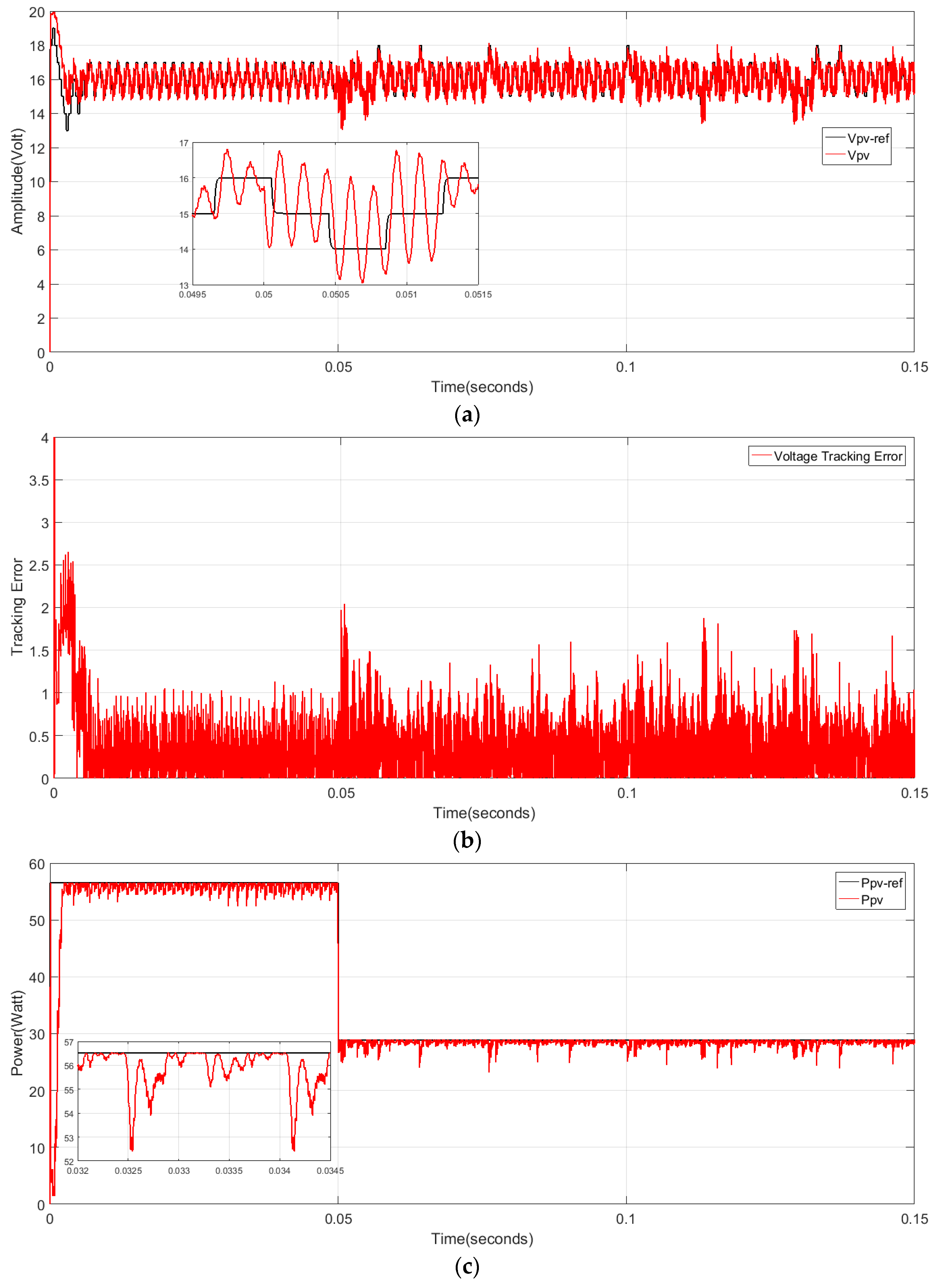
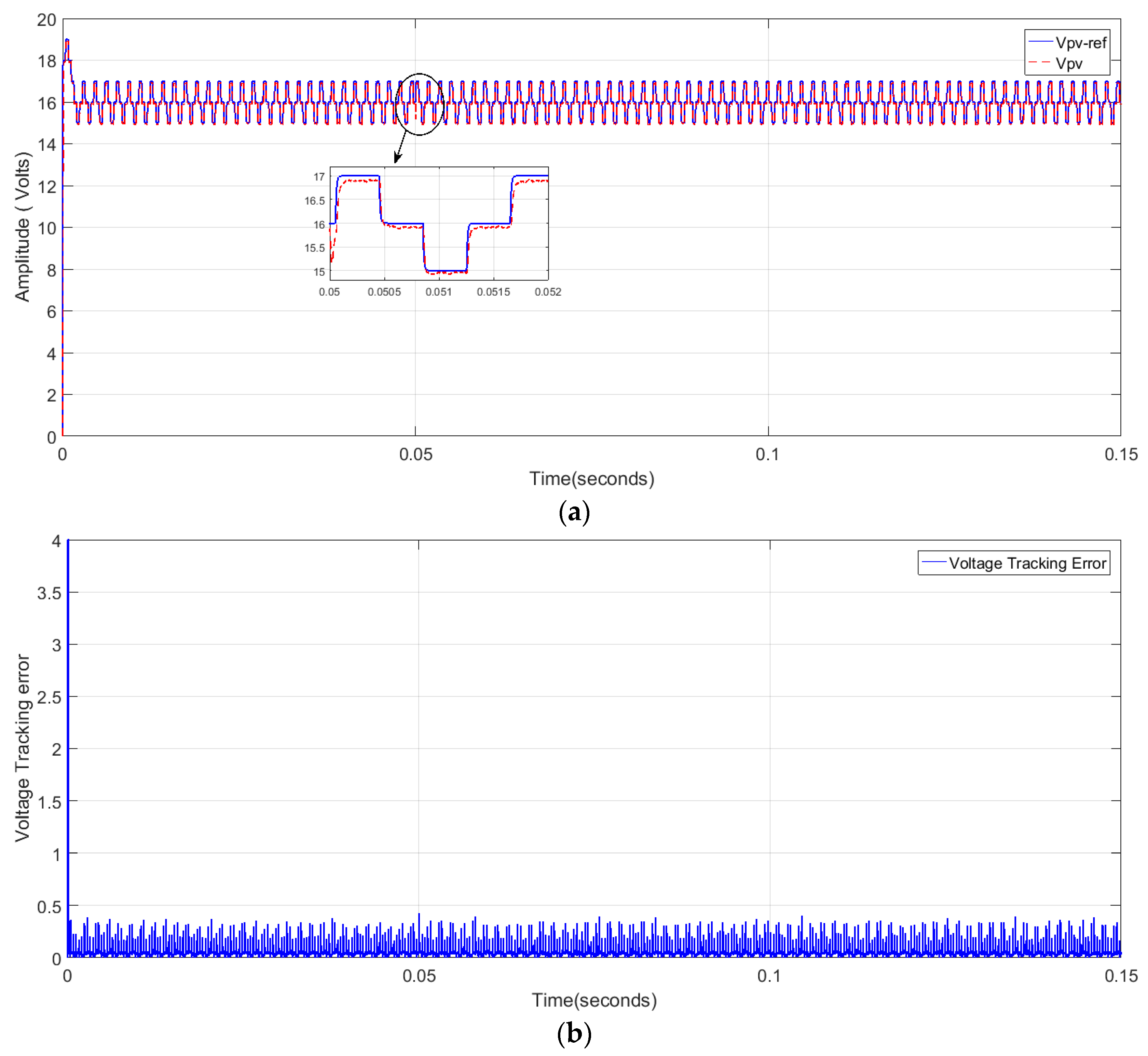
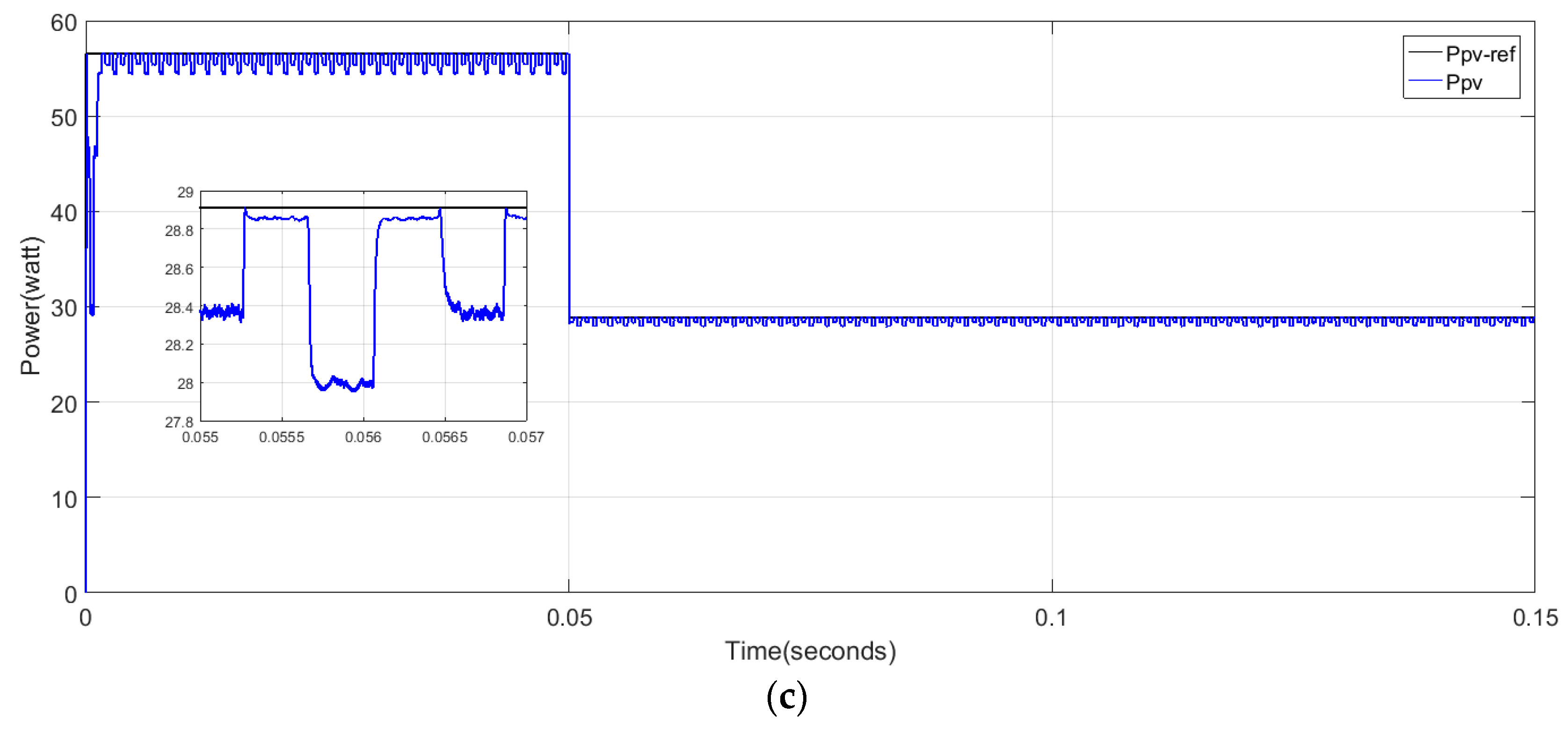
4.2. Response Using the Sliding Mode Controller (SMC)

The output of the P and O-based MPPT is a voltage reference which needs to be tracked by the controller. The controller is used to keep track of the panel voltage with the reference voltage generated by P and O and ensuring a tracking error around ‘zero’ for the desired performance of the proposed controller.
Figure 6a–c shows the performance of the SMC controller based on the P and O algorithm with a perturbation amplitude of 1 V under variable irradiance. It can be seen in Figure 6a that the panel voltage ‘Vpv’ starts following the reference generated voltage ‘Vpv-ref’ once it has reached the steady-state after transient behavior and successfully tracked the reference voltage. It is highlighted from the tracking response curve in Figure 6b that the proposed controller clearly outperforms the conventional controller with little oscillation. During the abrupt variation of irradiance at 0.05 s, the controller performed well, showing the robustness of the controller. The proposed controller is not only robust, but the ripples are also negligible. Similarly, the PV panel output power along with the reference power curve is shown in Figure 6c. It is observed that panel power ‘Ppv’ and reference power ‘Ppv-ref’ are following each other faster once they have reached the MPP.
The efficiency of the system is greatly enhanced when the proposed controller is used. The results that are obtained by using an improved SMC controller are free of ripples and overshoot, but with PID, both of them are high and visible.

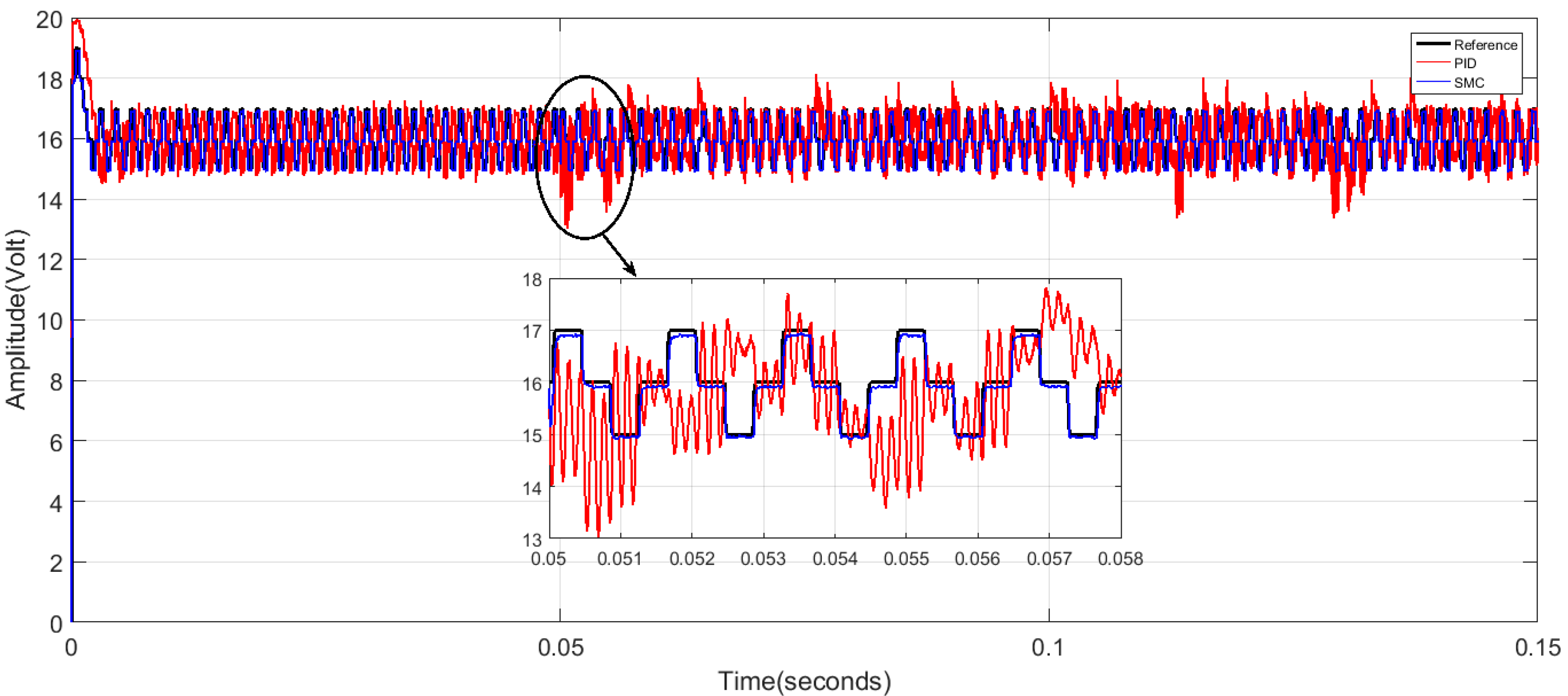
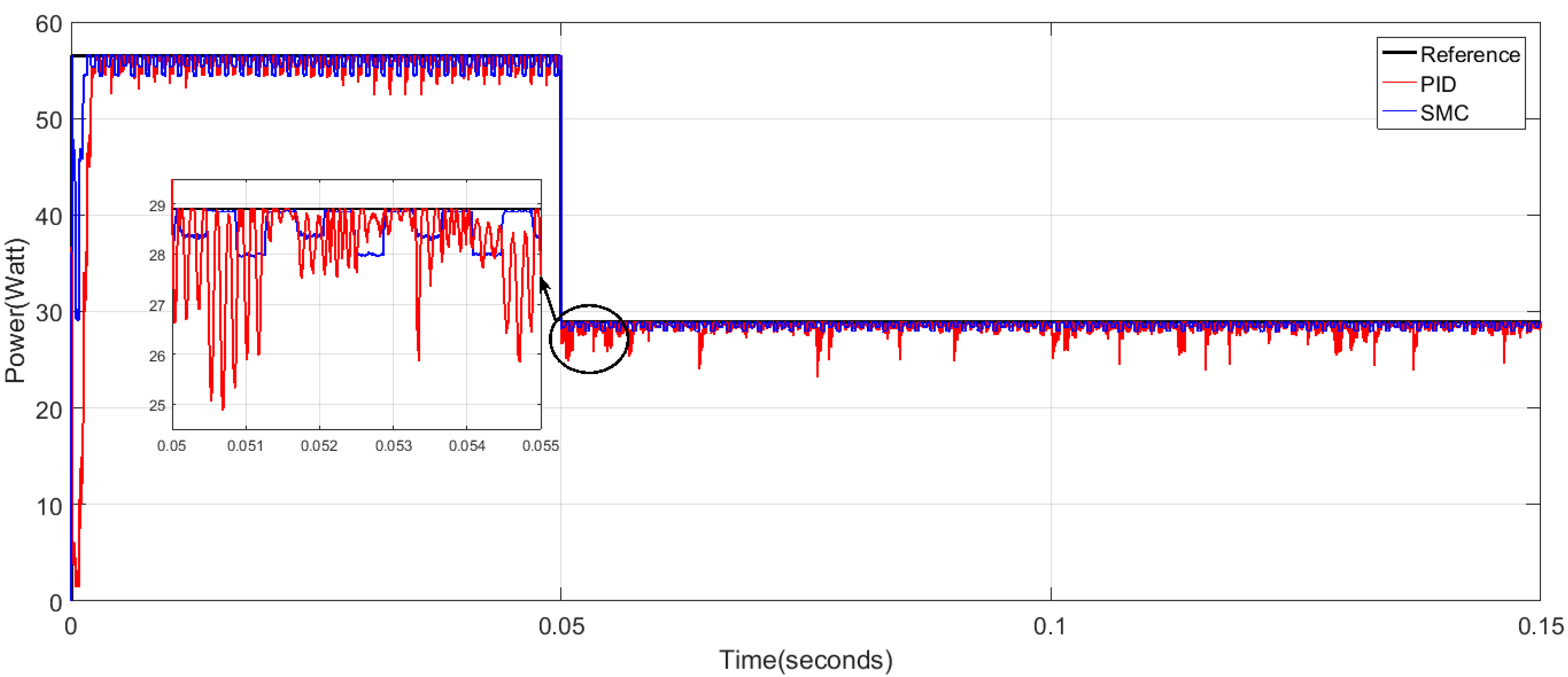
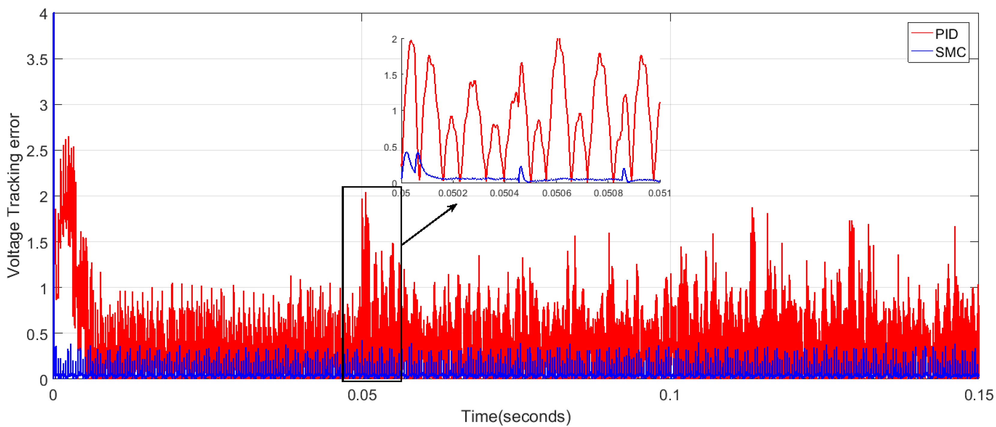
4.3. Comparative Analysis

Table 3 shows that the overshoot characteristics, response time, and power losses have been explained. It is possible to deduct from Table 3 that the performance characteristic parameters of the SMC controller in comparison with the PID controller for the proposed PV system have successfully improved. The comparison of the proposed SMC controller is done in Figure 7, Figure 8 and Figure 9. In Figure 7, the comparison of the proposed controller voltage curve is done with the reference signal and conventional controller voltage signal. Both controllers track the reference successfully, and there is high oscillation in the PID controller behavior. Similarly, Figure 8 highlights the comparative behavior of the proposed controller panel power with reference signal power and conventional controller power. It can be observed that MPP is successfully achieved by the proposed SMC controller with almost negligible ripples compared to the PID controller, which has large ripples in correspondence to the reference signal. The zoomed views are also shown to clearly observe the comparison. The tracking error comparative plot is shown in Figure 9, which shows high oscillations in the conventional controller response as compared to the proposed SMC controller which has little oscillations.

5. Conclusions

In this paper, a nonlinear sliding mode controller (SMC) based on a mathematical model of a boost converter has been derived for a photovoltaic system. The perturb and observe maximum power point tracking technique has been used to generate a voltage reference for the SMC controller. The closed loop system stability is shown to be guaranteed by using the Lyapounov stability criteria. The proposed control scheme is tested under varying irradiance levels and the simulation results are compared with a classical PID controller. From the simulation results, it is concluded that the proposed SMC control scheme overcomes the nonlinear dynamics of the PV system and offers a faster transient response with negligible power losses and minimum voltage ripples in comparison with the PID controller. As a next step, the authors look forward to an experimental validation of the results.

Author Contributions

H.G.A., R.V.A. and J.H. conceived and designed the experiments; H.G.A. and A.T. performed the simulations; J.P.-R. provided the PSIM simulation tools and access to laboratory; writing-review and editing, H.G.A., R.V.A., and J.H.; supervision, R.V.A.; H.G.A. wrote the paper. All authors have read and agreed to the published version of the manuscript.

Funding

This research was funded by the Spanish MINECO/FEDER grant DPI 2016-77271 And the APC was funded from this project.

Acknowledgments

This work was supported by the Spanish MINECO/FEDER grant DPI 2016-77271. The authors thank Santander bank as well as the National University of Science and Technology, Islamabad, Pakistan, for financial support during the completion of this research work.

Conflicts of Interest

The authors declare no conflict of interest.

References

  1. Ekins, P.; Bradshaw, M.J.; Watson, J. Global Energy: Issues, Potentials, and Policy Implications; Oxford University Press: Londong, UK, 2015. [Google Scholar]
  2. Growth of Renewable Energy Sources Generating ‘New World’: IRENA: Tüm Kaynaklar. Available online: http://eds.b.ebscohost.com/eds/pdfviewer/pdfviewer?vid=0&sid=3aba38c5-b09f-4638-a936-b90f83885d01%40pdc-v-sessmgr06 (accessed on 11 July 2019).
  3. Mohammadi, F.; Nazri, G.-A.; Saif, M. A Bidirectional Power Charging Control Strategy for Plug-in Hybrid Electric Vehicles. Sustainability 2019, 11, 4317. [Google Scholar] [CrossRef] [Green Version]
  4. Sims, R. Energy for Tomorrow’s World—A renewable energy perspective. Renew. Energy World 2000, 3, 24–30. [Google Scholar]
  5. Bonfiglio, A.; Brignone, M.; Delfino, F.; Procopio, R. Optimal control and operation of grid-connected photovoltaic production units for voltage support n medium-voltage networks. IEEE Trans. Sustain. Energy 2014, 5, 254–263. [Google Scholar] [CrossRef]
  6. Mehdipour, C.; Mohammadi, F. Design and Analysis of a Stand-Alone Photovoltaic System for Footbridge Lighting. J. Solar Energy Res. (JSER) 2019, 4, 85–91. [Google Scholar]
  7. Chaibi, Y.; Salhi, M.; El-Jouni, A. Sliding mode controllers for standalone PV systems: Modeling and approach of control. Int. J. Photoenergy 2019, 2019, 5092078. [Google Scholar] [CrossRef] [Green Version]
  8. Alba-Flores, R.; Lucien, D.; Kirkland, T.; Snowden, L.; Herrin, D. Design and Performance Analysis of three Photovoltaic Systems to Improve Solar Energy Collection. In Proceedings of the IEEE SoutheastCon, St. Petersburg, FL, USA, 19–22 April 2018; pp. 1–4. [Google Scholar]
  9. Metry, M.; Shadmand, M.B.; Balog, R.S.; Abu-Rub, H. MPPT of Photovoltaic Systems Using Sensorless Current-Based Model Predictive Control. IEEE Trans. Ind. Appl. 2017, 53, 1157–1167. [Google Scholar] [CrossRef]
  10. de Brito, M.A.G.; Galotto, L.; Sampaio, L.P.; Melo, G.D.; Canesin, C.A. Evaluation of the main MPPT techniques for photovoltaic applications. IEEE Trans. Ind. Electron. 2013, 60, 1156–1167. [Google Scholar] [CrossRef]
  11. Islam, H.; Mekhilef, S.; Shah, N.B.M.; Soon, T.K.; Seyedmahmousian, M.; Horan, B.; Stojcevski, A. Performance evaluation of maximum power point tracking approaches and photovoltaic systems. Energies 2018, 11, 365. [Google Scholar] [CrossRef] [Green Version]
  12. Sera, D.; Mathe, L.; Kerekes, T.; Spataru, S.V.; Teodorescu, R. On the perturb-and-observe and incremental conductance mppt methods for PV systems. IEEE J. Photovolt. 2013, 3, 1070–1078. [Google Scholar] [CrossRef]
  13. Femia, N.; Petrone, G.; Spagnuolo, G. Optimization of perturb and observe maximum power point tracking method. IEEE Trans. Power Electron. 2005, 20, 963–973. [Google Scholar] [CrossRef]
  14. Piegari, L.; Rizzo, R. Adaptive perturb and observe algorithm for photovoltaic maximum power point tracking. IET Renew. Power Gener. 2010, 4, 317. [Google Scholar] [CrossRef]
  15. Anto, E.K.; Asumadu, J.A.; Okyere, P.Y. PID control for improving P&O-MPPT performance of a grid-connected solar PV system with Ziegler-Nichols tuning method. In Proceedings of the 2016 IEEE 11th Conference Industrial Electronics and Applications (ICIEA), Hefei, China, 5–7 June 2016; pp. 1847–1852. [Google Scholar]
  16. Bianconi, E.; Calvente, J.; Giral, R.; Petrone, G.; Ramos-Paja, C.A.; Spagnuolo, G.; Vitelli, M. A fast current-based MPPT technique based on sliding mode control. In Proceedings of the 2011 IEEE International Symposium on Industrial Electronics, Gdansk, Poland, 27–30 June 2011; pp. 59–64. [Google Scholar]
  17. Khanna, R.; Zhang, Q.; Stanchina, W.E.; Reed, G.F.; Mao, Z.H. Maximum power point tracking using model reference adaptive control. IEEE Trans. Power Electron. 2014, 29, 1490–1499. [Google Scholar] [CrossRef]
  18. Chavarría, J.; Biel, D.; Guinjoan, F.; Meza, C.; Negroni, J.J. Energy-balance control of PV cascaded multilevel grid-connected inverters under level-shifted and phase-shifted PWMs. IEEE Trans. Ind. Electron. 2013, 60, 98–111. [Google Scholar] [CrossRef]
  19. Arsalan, M.; Iftikhar, R.; Ahmad, I.; Hasan, A.; Sabahat, K.; Javeria, A. MPPT for photovoltaic system using nonlinear backstepping controller with ntegral action. Sol. Energy 2018, 170, 192–200. [Google Scholar] [CrossRef]
  20. Iftikhar, R.; Ahmad, I.; Arsalan, M.; Naz, N.; Ali, N.; Armghan, H. MPPT for photovoltaic system using nonlinear controller. Int. J. Photoenergy 2018, 2018, 6979723. [Google Scholar] [CrossRef] [Green Version]
  21. Al, K.; Khan, L.; Khan, Q.; Ullah, S.; Ahmad, S.; Mumtaz, S.; Karam, F.W.; Naghmas. Robust Integral Backstepping Based Nonlinear MPPT Control for a PV System. Energies 2019, 12, 3180. [Google Scholar] [CrossRef] [Green Version]
  22. Levron, Y.; Shmilovitz, D. Maximum power point tracking employing sliding mode control. IEEE Trans. Circuits Syst. I Regul. Pap. 2013, 60, 724–732. [Google Scholar] [CrossRef]
  23. Liu, J. Sliding Mode Control Using MATLAB; Academic Press: Beijing, China, 2017. [Google Scholar]
  24. Liu, J. Design, Intelligent Control Design and MATLAB Simulation; Springer: Singapore; Beijing, China, 2018. [Google Scholar]
  25. Tan, S.C.; Lai, Y.M.; Tse, C.K. General design issues of sliding-mode controllers in DC-DC converters. IEEE Trans. Ind. Electron. 2008, 55, 1160–1174. [Google Scholar]
  26. Montoya, D.G.; Paja, C.A.R.; Giral, R. A new solution of maximum power point tracking based on sliding mode control. In Proceedings of the IECON 2013—39th Annual Conference of the IEEE Industrial Electronics Society, Vienna, Austria, 10–13 November 2013; pp. 8350–8355. [Google Scholar]
  27. Tobón, A.; Peláez-Restrepo, J.; Villegas-Ceballos, J.; Serna-Garcés, S.; Herrera, J.; Ibeas, A. Maximum Power Point Tracking of Photovoltaic Panels by Using Improved Pattern Search Methods. Energies 2017, 10, 1316. [Google Scholar] [CrossRef] [Green Version]
  28. Montoya, D.G.; Ramos-Paja, C.A.; Gira, R.L. Improved Design of Sliding-Mode Controllers Based on the Requirements of MPPT Techniques. IEEE Trans. Power Electron. 2016, 31, 235–247. [Google Scholar] [CrossRef] [Green Version]
  29. Attivissimo, F.; di Nisio, A.; Savino, M.; Spadavecchia, M. Uncertainty analysis in photovoltaic cell parameter estimation. IEEE Trans. Instrum. Meas. 2012, 61, 1334–1342. [Google Scholar] [CrossRef]
  30. Ahmad, T.; Sobhan, S.; Nayan, F. Comparative Analysis between Single Diode and Double Diode Model of PV Cell: Concentrate Different Parameters Effect on Its Efficiency. JPEE 2016, 4, 31–46. [Google Scholar] [CrossRef] [Green Version]
  31. Cuk, S.; Middlebrook, R.D. Advances in Switched-Mode Power Conversion Part II. IEEE Trans. Ind. Electron. 1983, IE-30, 19–29. [Google Scholar] [CrossRef] [Green Version]
  32. Tutorial, P. How to Use Solar Module Physical Model. Available online: https://powersimtech.com/drive/uploads/2016/04/Tutorial-Solar-Module-physical-model.pdf (accessed on 1 April 2016).
  33. SOLAREX. MSX-60 and MSX-64 Photovoltaic Modules; SOLAREX: Frederick, MD, USA, 1997; pp. 347–368. [Google Scholar]
Figure 1. System scheme based on a classical proportional integral derivative (PID) control.
Processes 08 00108 g001
Figure 2. System scheme based on the improved sliding mode controller (SMC).
Processes 08 00108 g002
Figure 3. Photovoltaic (PV) panel double-diode model representation.
Processes 08 00108 g003
Figure 4. Perturb and observe (P and O) algorithm.
Processes 08 00108 g004
Figure 5. (a) Profile of the PV panel voltage, (b) tracking response of the proposed PID controller, and (c) profile of the PV power extraction.
Processes 08 00108 g005
Figure 6. (a) Profile of the PV panel voltage, (b) tracking response of the proposed SMC controller, and (c) profile of power extraction.
Processes 08 00108 g006aProcesses 08 00108 g006b
Figure 7. Reference, PID, and SMC PV voltage curve.
Processes 08 00108 g007
Figure 8. Reference, PID, and SMC PV power curve.
Processes 08 00108 g008
Figure 9. PID and SMC PV tracking error curve.
Processes 08 00108 g009
Table 1. Parameters of the PV array [33].
SymbolParameterValue
IscOpen circuit current3.8 A
VocOpen circuit voltage21.1 V
ImpMaximum panel current3.5 A
VmpMaximum panel voltage17.1 V
Is1 = s2Saturation currents4.704 × 10−10
IpvPanel current3.8 A
RshShunt resistance176.4 Ω
RsSeries resistance0.35 Ω
Table 2. Parameters of controller, converter, and maximum power point tracking (MPPT).
ParameterValue
L22 µF
C100 µF
Vo24 V
fsho49.9 kHz
Kp0.1
Kd0.1
Ki50
Ks (MPPT)14.53
Ta400 µs
ΔVoIV (P and O)
LPF20 kHz
LPF (low pass filter).
Table 3. Performance characteristics of the conventional PID and the proposed SMC controller.
ControllerOver/Undershoot (%)Settling Time (s)Power Losses (Watt)
PID2.615 ms3
SMC0.60.3 ms0.68

