Article

Numerical Investigation of Solid-Fueled Chemical Looping Combustion Process Utilizing Char for Carbon Capture

1
Key Laboratory of Energy Thermal Conversion and Control of Ministry of Education, School of Energy and Environment, Southeast University, Nanjing 210096, China
2
China Energy Engineering Group Jiangsu Power Design Institute Co. Ltd., Nanjing 211102, China
*
Author to whom correspondence should be addressed.
Processes 2019, 7(9), 603; https://doi.org/10.3390/pr7090603
Submission received: 20 July 2019 / Revised: 1 September 2019 / Accepted: 3 September 2019 / Published: 6 September 2019
(This article belongs to the Section Chemical Processes and Systems)

Abstract

:
The in-depth understanding of the gas–solid flow and reaction behaviors, and their coupling characteristics during the chemical looping combustion (CLC) process has the guiding significance for the operation and optimization of a chemical looping combustor. A three-dimensional numerical model is applied to investigate the char-fueled CLC characteristics in a fuel reactor for efficient CO2 separation and capture. Simulations are carried out in a bubbling fluidized bed fuel reactor with a height of 2.0 m and a diameter of 0.22 m. The initial bed height is 1.1 m, and hence the height–diameter ratio of the slumped bed is five. The oxygen carrier is prepared with 14 wt% of CuO on 86 wt% of inert Al2O3. In the process of mathematical modeling, a Eulerian-Eulerian two-fluid model is adopted for both of the gas and solid phases. Gas turbulence is modeled on the basis of a k–ε turbulent model. The reaction kinetics parameters are addressed based upon previous experimental investigations from literature. During the simulation, the gas–solid flow patterns, composition distributions, and reaction characteristics are obtained. Moreover, the effects of solids inventory and fluidizing number on the reaction performance are elucidated in-depth. The results have shown that the reaction rates have close relationship with the flow patterns and the distributions of gas concentrations. Compared to the steam-char gasification over sand, the application of char-fueled CLC can effectively promote the conversion of gasification products. In addition, higher CO2 concentration at the outlet can be achieved by increasing the initial solids inventory or decreasing the fluidizing number. Some calculated values are verified by the previous data, indicating that the current three-dimensional models are reasonable to study the process mechanism of char-fueled CLC.

1. Introduction

With the deterioration of global warming, the emission of greenhouse gas CO2 has drawn increasing attention. Many technologies, such as amine scrubbing in post-combustion, chemical looping combustion (CLC), and oxy-fuel combustion, have been proposed to be applied in the electric power industry so as to reduce the greenhouse effect by CO2 [1,2,3,4,5]. Among them, CLC technology, by virtue of its intrinsic attribute of isolating CO2 during the combustion process, is regarded as the most promising option in CO2 separation and capture with a low energy cost [3,6].
The basis for the concept of CLC is the transfer of oxygen from air to fuel by the circulation of a solid oxygen carrier, which is commonly a kind of metallic oxide. Figure 1 is a conventional scheme with CuO/Cu for CLC. This system mainly includes two reactors, known as the fuel reactor and air reactor. The fuel reactor is a bubbling fluidized bed (BFB) in which the oxygen carrier is reduced by the fuel. When the fuel is fully converted, there are only steam and CO2 in the flue gases of fuel reactor. Thus, after condensation, a CO2 stream with high purity can be obtained. Then, the reduced oxygen carrier is circulated into the air reactor (usually with a high velocity fluidized bed structure) for re-oxidization by reacting with the air [7,8].
Since the concept of CLC was firstly proposed, the CLC processes with gaseous fuels have been deeply investigated [9,10,11,12,13,14,15]. However, due to the more abundant reserves of solid fuels (e.g., coal, char, and biomass) in comparison to gaseous fuels, the adaptation of gas-fueled CLC technology to the solid-fuel combustion is very attractive and necessary [16,17,18,19]. At present, the application of solid-fuel CLC is mainly carried out by an approach entitled in-situ gasification chemical looping combustion (iG-CLC). In contrast to gas-fueled CLC, the special feature of iG-CLC is that it integrates the gasification reactions of solid fuels and the subsequent chemical-looping reactions between the gasification products and the oxygen carrier in the fuel reactor [19,20,21,22]. Specifically, in the fuel reactor, the fuel (represented by char) is first gasified by H2O and CO2 as the following reactions:
C ( s ) + H 2 O ( g ) C O ( g ) + H 2 ( g )   ( Δ H 1073   K θ = 134.9   kJ / mol )  
C ( s ) + C O 2 ( g ) 2 C O ( g )   ( Δ H 1073   K θ = 169.0   kJ / mol )
The water–gas shift reaction (WGSR) also plays an important role when steam is the main gasification agent [23]:
C O ( g ) + H 2 O ( g ) C O 2 ( g ) + H 2 ( g )   ( Δ H 1073   K θ = 34.0   kJ / mol )
The oxygen carrier (represented by CuO) is then reduced by the intermediate gasification productions to generate H2O and CO2:
C u O ( s ) + H 2 ( g ) C u ( s ) + H 2 O ( g )   ( Δ H 1073   K θ = 98.9   kJ / mol )
C u O ( s ) + C O ( g ) C u ( s ) + C O 2 ( g )   ( Δ H 1073   K θ = 132.9   kJ / mol )
In the air reactor, the reduced oxygen carrier is re-oxidized by reacting with the oxygen from the air:
C u ( s ) + 1 / 2 O 2 ( g ) C u O ( s )   ( Δ H 1073   K θ = 149.4   kJ / mol )
The iG-CLC option has been demonstrated in various pilot-scale experiments [24,25,26,27,28,29,30,31,32,33,34] and all these tests show that this technique is feasible and promising. However, currently, there still exist some difficulties confining its development, mainly with respect to the unsatisfactory fuel conversion and CO2 concentration in the fuel reactor. These two issues are believed to be mainly related to the following factors: (1) The mismatching between the slow reactions of char gasification and the rapid flameless combustion reactions between the gasification products and the oxygen carrier [22,35,36]. (2) The unsatisfactory gas–solid flow and contact efficiency in the fluidized bed fuel reactor, including gas bypassing via bubbles, particle cluster, agglomeration, and so on [22,37]. Under the circumstances, a deep understanding of the flow and reaction characteristics in the fuel reactor is significant to the optimization of iG-CLC performance for higher fuel conversion, CO2 concentration, and CO2 capture efficiency. However, to date, related investigations into the gas–solid flow and reaction characteristics mainly focus on the experimental measurements which have a lot of difficulty in acquiring detailed dynamics mechanism without disturbing the original flow field.
With the fast-developing computational technology and simulation methods, computational fluid dynamics (CFD) simulations have been accepted as an important tool to predict complex gas–solid hydrodynamics and reaction mechanisms without breaking gas–solid dynamics properties. Adamczyk et al. [38] constructed a three-dimensional large-scale boiler model to predict the pulverized coal combustion process. Liu et al. [39] successfully integrated a particle shrinkage model into the Eulerian multiphase CFD frame work to describe the fast fluidized-bed pyrolysis of biomass. Wu et al. [40] established a three-dimensional circulating fluidized bed (CFB) model to study the profiles of hydrodynamics, temperature, and gas emission during the oxy-fuel combustion process with a warm flue gas recycle. Nam et al. [41] performed a CFD simulation to predict the effects of different jet/grid air ratio and pressure conditions on the hydrodynamics characteristics of a pilot-scale pressurized fluidized bed gasifier. By far, the simulation studies with CFD method on CLC mainly focus on the gas-fueled CLC [42,43,44,45,46,47,48,49,50,51,52] and fluid dynamics in CLC systems [53,54,55,56], and only a few of them have probed into the field of solid-fuel CLC. Mahalatkar et al. [57] pioneered the prediction of solid-fuel CLC performance in the fuel reactor using a two-dimensional model. However, the continuous charging was not viable for their model. Su et al. [58] performed a two-dimensional simulation of a dual circulation fluidized bed (DCFB) iG-CLC system. They investigated the gas leakage behaviors, flow characteristics and combustion performance in the reaction process with coal as fuel. In comparison to three-dimensional simulations, a two-dimensional simulation will inevitably lead to a certain degree of deviation in terms of the reactor geometry and the influence of the wall boundary, which will further affect the prediction accuracy of gas–solid flow and reaction patterns. Hence, it is necessary to develop three-dimensional numerical models in order to study the CLC performance of solid fuel. Sharma et al. [59] and May et al. [60] built a three-dimensional CFB fuel reactor model to predict the hydrodynamics of a megawatt chemical-looping combustion plant. The calculation results for the pressure distribution along the fuel reactor height agreed well with the experimental values. Nevertheless, some deviations were found with respect to the concentration distributions of gas species, which was believed to be related to the improper reactions of the combustible gases with the oxygen carrier. In our previous studies, we have also carried out a series of simulations on CLC. We first developed a three-dimensional numerical model to simulate the gas-fueled CLC process in the BFB fuel reactor [61,62]. Thereafter, we successfully built a fuel reactor model with the high-flux circulating fluidized bed (HFCFB) structure to investigate the fundamental features of iG-CLC, including composition distributions, fuel conversions, reaction rates, in the fuel reactor [63,64]. Further, we also developed a cold-state full-loop three-dimensional a model to predict the directional separation processes of the fine coal particles and the coarse oxygen carrier particles in an HFCFB iG-CLC system [65]. However, few three-dimensional simulation studies have been carried out on the solid-fuel CLC characteristics in a more typical BFB fuel reactor, which includes the challenge of continuous feeding in the dense phase zone. In addition, as mentioned above, the fundamental reaction mechanism of char gasification which is considered as the rate-controlling step of the whole system, and the matching relation between the char gasification reactions and the subsequent redox reactions of the gasification products with the oxygen carrier are still lacking. Also, it’s necessary to conduct in-depth investigations of the coupling mechanism between the flow and reaction behaviors.
Extending from the previous studies, this work builds a three-dimensional CFD model to predict the process of char-fueled iG-CLC in a BFB fuel reactor. The gas–solid flow patterns, composition distributions, heterogeneous reactions, and other important characteristics are predicted. The results of these numerical investigations provide a deep understanding of the hydrodynamics and reaction characteristics in the iG-CLC system, which should be hard to come by under the current experimental conditions, and therefore should be significant for the further development of iG-CLC applications. Compared to the previous simulation studies, the main contributions of this work include: (1) realization of continuous feeding in the dense phase zone of a BFB fuel reactor with a three-dimensional model, (2) investigations of the reaction mechanism of char gasification and its matching relation with the subsequent redox reactions of the gasification products with the oxygen carrier, (3) in-depth understanding of the coupling mechanism between the flow and reaction behaviors in the iG-CLC process, and (4) revelation of the differences of reaction performance between the iG-CLC and gas-fueled CLC under different operation conditions.

2. Materials and Methods

The fuel reactor selected in this simulation work is a BFB reactor [66]. As shown in Figure 2, the main geometry of the reactor is 2 m for the height, 0.22 m for the diameter. Besides, the initial bed height is 1.1 m with the height-diameter ratio of 5.

2.1. Hydrodynamic Models

In this work, in order to get a good convergence, we assume that the particles are spherical and inelastic with uniform size and density, and the difference of temperature in the reactor is neglected. The Eulerian–Eulerian two-phase model is applied to simulate the multiphase flow in the BFB fuel reactor.
The continuity equations for gas and solid phases are given by Equations (7) and (8):
t ( α g ρ g ) + · ( α g ρ g v g ) = m ˙ g p
t ( α p ρ p ) + · ( α p ρ p v p ) = m ˙ p g
where α , ρ and v represent the volume fraction, density, and velocity, respectively, m ˙ g p and m ˙ p g are the mass source terms generated by the heterogeneous reactions, and the subscripts g and p represent gas phase and particle phase, respectively.
The momentum equations for gas and solid phases are given by Equations (9) and (10):
t ( α g ρ g v g ) + · ( α g ρ g v g v g ) = α g p + · τ ¯ ¯ g + α g ρ g g + m ˙ g p v g + β ( v p v g )
t ( α p ρ p v p ) + · ( α p ρ p v p v p ) = α p p p p + · τ ¯ ¯ p + α p ρ p g + m ˙ p g v p + β ( v g v p )
where β is the drag coefficient between the gas phase and particle phase.
The energy conservation equations for gas and solid phases are given by Equations (11) and (12):
t ( α g ρ g H g ) + · ( α g ρ g v g H g ) = · ( λ g T g ) + h g p ( T g T p ) + m ˙ g p H g
t ( α p ρ p H p ) + · ( α p ρ p v p H p ) = · ( λ p T p ) + h p g ( T p T g ) + m ˙ p g H p
where H and λ represent the specific enthalpy and the mixture thermal conductivity, respectively. h g p and h p g are the heat transfer coefficient between phases.
The species transport equations are solved for individual species in each phase, taking the forms of Equations (13) and (14):
t ( α g ρ g Y g , i ) + · ( α g ρ g Y g , i v g ) = · α g J g , i + m ˙ g , i
t ( α p ρ p Y p , i ) + · ( α p ρ p Y p , i v p ) = m ˙ p , i
where J g , i represents the diffusion flux of species i.
The stress tensors of the gas and solid phases are defined in Equations (15) and (16):
τ = g = α g μ g [ v g + ( v g ) T ] 2 3 α g μ g · v g I =
τ = p = α p μ p v p + ( v p ) T + α p ( ξ p 2 3 μ p ) · v p I =
where μ g and μ p are the shear viscosities of gas phase and solid phase, respectively. ξ p is the bulk viscosity of solid phase.
The standard k-ε turbulent model is adopted to describe the turbulence of gas phase [64,67,68]:
t ( α g ρ g κ ) + · ( α g ρ g v g κ ) = · ( α g μ g t σ κ κ ) + α g G κ α g ρ g ε + α g ρ g Π κ
t ( α g ρ g ε ) + · ( α g ρ g v g ε ) = · ( α g μ g t σ ε ε ) + α g ε κ ( C 1 G κ C 2 ρ g ε ) + α g ρ g Π ε
where G κ represents the production of turbulent kinetic energy, Π κ and Π ε are the turbulence exchange terms between phases.
The kinetic theory of granular flow is used for modeling the rheology of the particle phase [69]:
t ( α p ρ p Θ ) + · ( α p ρ p v p Θ ) = 2 3 [ ( p p I = + τ = p ) : v p + · ( Γ Θ Θ ) γ p + φ p ]
where Θ is the granular temperature reflecting the kinetic energy of solids random motion; Γ Θ , γ p and φ p represent the diffusion coefficient, the energy collisional dissipation, and the energy exchange between gas–solid phases, respectively.
The Gidaspow model, which can selectively calculate the gas–solid drag coefficient β in the dilute or dense phases, is selected as the drag model in this study [70]:
β = { 0.75 C D α p α g ρ g | v p v g | d p α g 2.65 ,   ( α g > 0.8 ) 150 α p 2 μ g α g d p 2 + 1.75 ρ g α p | v p v g | d p ,   ( α g 0.8 )

2.2. Chemical Reaction Models

The solid phase consists of char, CuO, Cu and Al2O3, and the gas phase consists of CO2, H2, CO, H2O and N2. The reactions occurred in the fuel reactors involve heterogeneous reactions of gasification, homogeneous water gas shift (WGS) reaction and heterogeneous reduction reactions of oxygen carrier, i.e., Equations (1)–(5).The reaction rates follow the Arrhenius equation, and the pre-exponential factors and activation energy are acquired from the literature [7,66,71]. Table 1 lists the detailed formulas of the heterogeneous reaction rates.

2.3. Initial Conditions and Boundary Conditions

A three-dimensional geometry is adopted in this simulation work. The finite volume method is used for the solution of the governing equations. The second-order upwind discretization is selected for all solutions. The time step of 1 × 10⁻⁴ s and the convergence criterion of 1 × 10⁻⁴ are applied for calculation. After mesh independent analysis, the grids with the size of 22 mm × 22 mm × 22 mm are adopted in the most zones while the mesh refinements are applied near the inlets.
The velocity inlet and outflow are chosen as the boundary conditions of the inlet and outlet, respectively. At the walls, the no-slip condition is considered for both of the gas and solid phases. Initially, the particles of oxygen carrier accumulate in the fuel reactor under N2 atmosphere. The initial volume fraction of solid phase is set to be 0.55 with the bed height of 1.1 m. The selected oxygen carrier is the so-called Cu14Al-I which contains 14 wt% of CuO as the active component and 86 wt% of inert Al2O3 [61,62,72]. The detailed model parameters and initial conditions used in the simulations are summarized in Table 2.

3. Results and Discussion

3.1. Flow Patterns and Composition Distributions

Initially, the particles of oxygen carrier suspend in the space of inert gas (N2). When the calculation is started, the stream of gasification agent (H2O) is injected into the reactor from the bottom distributor, while the fuel char is transported by N2 into the inlet in the side of the reactor.
Most of the bubble features such as formation, rise, and collapse are observed in Figure 3a, where the blue color illustrates the pure gas atmosphere and the red color represents the maximum solids holdup. Meanwhile, we can see the bed expansion due to the existence of bubbles. The computed flow patterns predict a global gas–solid mixing in the bed. The axial molar fraction distributions of gas compositions are presented in Figure 3b,c, where the blue and red colors represent the minimum and maximum species concentrations, respectively. Some differences can be found between the fluidized regime and freeboard region. In the fluidized regime, CO2 is generated from the chemical looping reaction of one of the gasification products CO with the oxygen carrier. Generally, the concentration of CO2 increases along the bed height. However, the average of CO2 concentration within the bubbles is smaller than that at the nearby emulsion zone, implying that the presence of bubbles has a negative effect on the sufficient contact and reaction of gas–solid reactive components. On the other side, the CO2 concentration in the freeboard keeps nearly constant, reflecting a serious dent of heterogeneous reactions in this region due to the lack of particle phase. On the other hand, the molar fraction of H2O goes down with the reactor height in the fluidized regime due to the continuous production of CO2, and it almost keeps constant in the freeboard. Compared to the sole role as the product in gas-fueled CLC, H2O in iG-CLC plays the roles of both the chemical looping product and the gasification agent. Hence, different with the continues increase of concentration along the bed height for gas-fueled CLC [61,62], the concentration of H2O for iG-CLC presents a downward trend due to the consumption from char gasification. Figure 3d gives the mass fraction distribution of char, which presents a low concentration in the fluidized regime, indicating the char is mostly consumed from the gasification reactions. It should be noted that because the fuel reactor model developed in this study doesn’t consider the regular deslagging, it will inevitably lead to a certain degree of accumulation of unreacted char with the process of calculation.
Generally, the bubbles in the BFB fuel reactor can effectively promote particle motions, and hence the mixing with the gas phase. However, in contrast, the bubbles capture and envelop a part of the intermediate reactive gases from gasification, which will cause the isolation of the reactive gases and the oxygen carrier particles, and further limit the chemical looping reaction efficiency. [61,73].
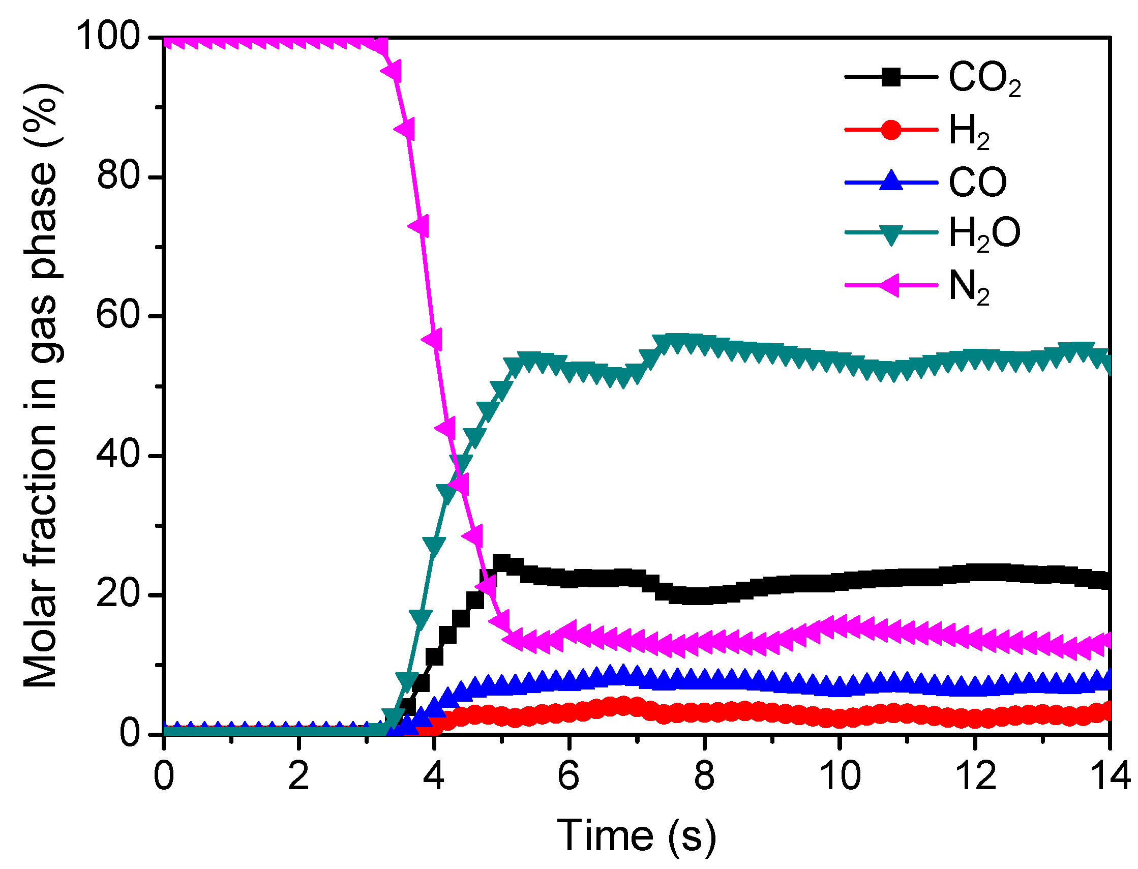
Figure 4 displays the variations in the molar fractions of gas compositions with time at the outlet of the fuel reactor. The composition distribution can be categorized into three periods, according to the variation trend with computation time. In the first period, i.e., when the computation time is less than 3.2 s, the molar fraction of N2 always equals to one while the other gas compositions remain zero, indicating the calculation process has not yet reached the outlet. Thus, the first stage can be called as the initialization stage. In the second period, i.e., when the computation time is between the range of 3.2 s to 5 s, the concentrations of all the gas compositions present rapid time-varying characteristics. Specifically, the molar fraction of N2 decreases rapidly, while the other compositions increase fast. According to the variation characteristics, this period can be referred to as the transition stage. When the downward concentration of N2 reaches the minimum, i.e., when the computation time is larger than 5 s, it comes to the third period, so called the stable stage. In this period, all of the gas concentrations reach quasi-equilibrium state, just with slight fluctuations. The average values of the gas compositions in this stage are obtained to be about 3.0% for H2, 7.2% for CO, 54.0% for H2O, and 22.1% for CO2. In conclusion, based upon the time-varying characteristics, the calculation should ensure reach the stable stage where the calculation results can be acquired with the time-averaging method.

3.2. Model Validation and Reaction Performance Evaluation

Before further modeling research, the simulation of steam-char gasification with sand as the bed material has been carried out for the model validation and providing reference to the reaction performance evaluation of iG-CLC. Figure 5 shows a comparison of the computed exhaust concentrations from steam-char gasification reaction over sand with the previous data [66]. The calculated gas concentrations agree well with the previous data. As a whole, the relative error of calculation is less than 8%, which illustrates the reasonability of the simulation results and the validity of the present model.
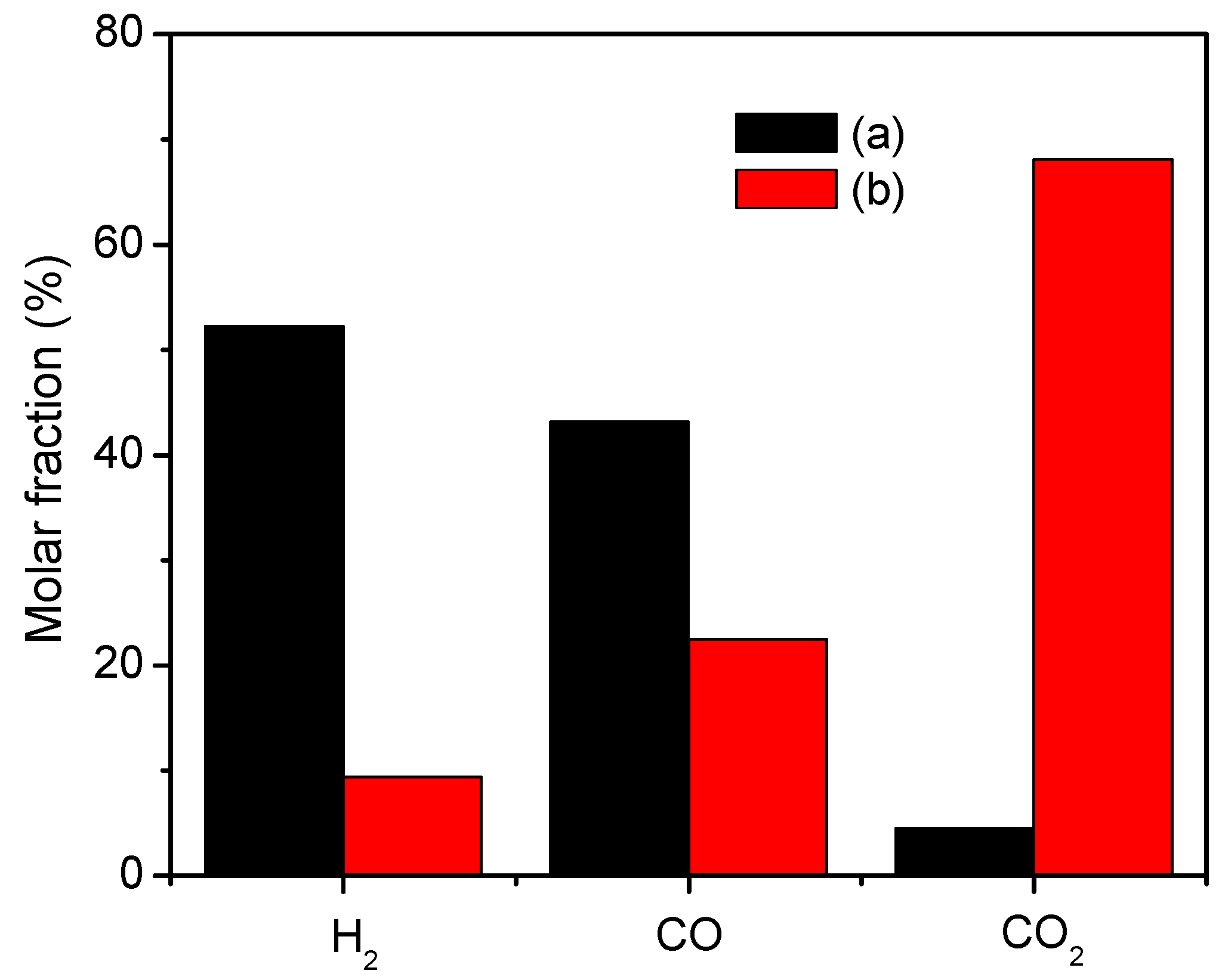
Figure 6 presents a comparison of N2-excluded flue gas concentrations (dry basis) with different solid materials. It can be found that the flue gas concentrations change a lot from gasification to iG-CLC. The mean concentrations of H2 and CO at the outlet for steam-char gasification over sand are 52.3% and 43.2%, which decrease to 9.4% and 22.5% for char-fueled iG-CLC, respectively. Meanwhile, the CO2 concentration increase from 4.5% for gasification to 68.1% for iG-CLC. Through the comparison we can conclude that most of the intermediate gasification products have been consumed by the oxygen carrier during the process of iG-CLC.

3.3. Patterns of Gas–Solid Reactions

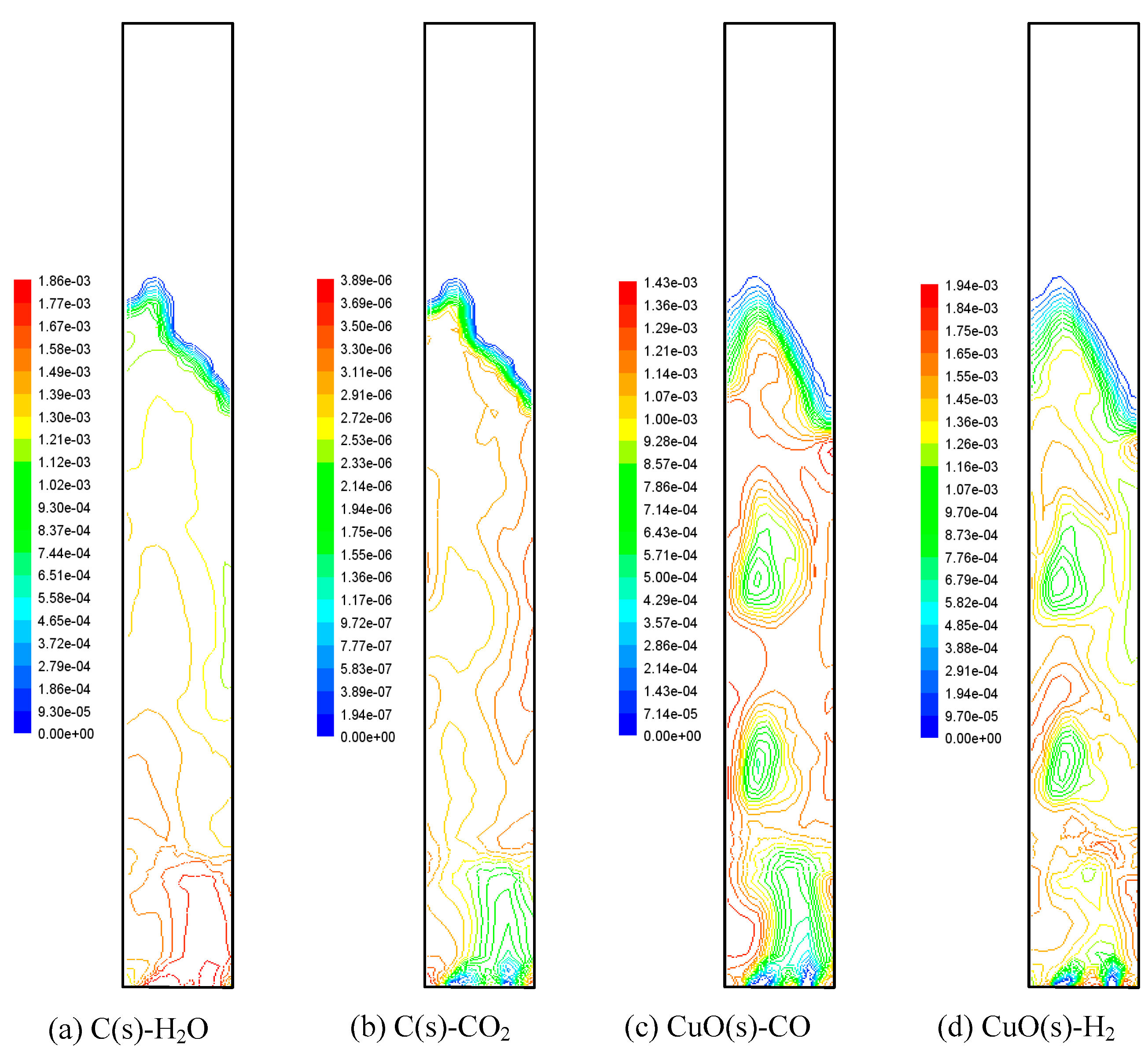
The reaction process in the iG-CLC process is complex because it involves not only the matching relation between the char gasification and the subsequent chemical-looping reactions of the gasification products with the oxygen carrier, but also the coupling relationship between the flow and reaction behaviors. Hence, the in-depth understanding of the iG-CLC reaction mechanism has significant meaning for the further development of iG-CLC applications. Figure 7 displays the axial distributions of heterogeneous reactions in the fuel reactor, where the color range from blue to red illustrates the change of reaction rate from minimum to maximum.

3.3.1. Gasification Reactions of Char

Figure 7a,b shows the gasification reactions of C(s)-H2O and C(s)-CO2. It can be seen that the reaction rate of C(s)-CO2 is much lower than that of C(s)-H2O, which is believed to be mainly related to the much lower reactivity of CO2 than H2O with char, and also the lower concentration. This demonstrates that the steam is a better candidate as the gasification agent during the operation temperature range of iG-CLC. On the other hand, by comparison of Figure 3c and Figure 7a, we can observe a close bond between the gasification reaction rate of C(s)-H2O and the concentration distribution of H2O. The C(s)-H2O rate drops along the bed height because the concentration and further the partial pressure of H2O decline during its ascent. On the contrary, from Figure 3b and Figure 7b, it can be found that the C(s)-CO2 rate increases with the bed height as more CO2 is generated in the higher area.

3.3.2. Chemical-Looping Reactions of Oxygen Carrier

Figure 7c,d displays the chemical-looping reactions of the intermediate gasification products and the Cu-based oxygen carrier. By comparison with Figure 7a, we can observe that the reaction rates of CuO(s)-CO and CuO(s)-H2 are at the same level with the gasification rate of C(s)-H2O. This reflects the high reactivity of the Cu-based oxygen carrier selected, which can ensure the timely conversion of the gasification products. Besides, by integrating the rate equations shown in Table 1, we can further find that the in-time consumption of the intermediate gasification products can guarantee the concentration of gasification agents, and further promote the front-end gasification rate. This illustrates the positive role of the direct mixing of oxygen carrier and fuel in the global reaction rate of the iG-CLC approach, by considering that the C(s)-H2O gasification is the rate-determining step of all the reactions [23,63,74]. In addition, according to Figure 3 and Figure 7, we can further find that the chemical-looping reaction rates of CuO(s)-H2 and CuO(s)-CO are also related to the flow patterns. Specifically, in the area where bubbles exist, the chemical looping rates are lower, which will further lead to a relatively low combustion efficiency. This observation demonstrates the negative effect of bubbles on the sufficient contact and reaction of gas–solid components, as mentioned in Section 3.1.

3.4. Influence of Solids Inventory

The solids inventory of the fuel reactor is one of the most important operating variables influencing the performance of a CLC system. Hence, three different cases have been carried out to study the influence of solids inventory (represented by the initial bed height) on the iG-CLC performance.
Figure 8 exhibits the distributions of N2-excluded flue gas concentrations (dry basis) in different solids inventories. The concentrations of H2 and CO at the outlet decrease with the increase of solids inventory while it is on the contrary for CO2. The average molar fractions of H2 and CO are 11.1% and 22.4% for the initial bed height of 0.9 m, and decrease to 8.2% and 20.8% for 1.3 m, respectively. The mean value of CO2 fraction is 64.4% at the bed height of 0.9 m, which increases to 71.1% at that of 1.3 m. The results illustrate that solids inventory promotes the increase of the fuel conversion and CO2 concentration. But it should be pointed out that the increase of solid inventory will also increase the system size and operation cost. Therefore, in order to select a suitable solid inventory, the comprehensive consideration of combustion efficiency and investment cost is necessary.
In addition, compared to our previous studies on the gas-fueled CLC [62], the influence of solids inventory on the fuel gas conversion is far smaller in the iG-CLC process. This is mainly because that in gas-fueled CLC, the increase of solids inventory can directly increase the reaction time and contact probability between the fuel gas and oxygen carrier. However, in the iG-CLC process, the chemical looping reaction rates between the oxygen carrier and the intermediate gasification products are mainly limited by the front-end slow reaction of char gasification, which further weakens the facilitation of solids inventory.

3.5. Influence of Fluidizing Number

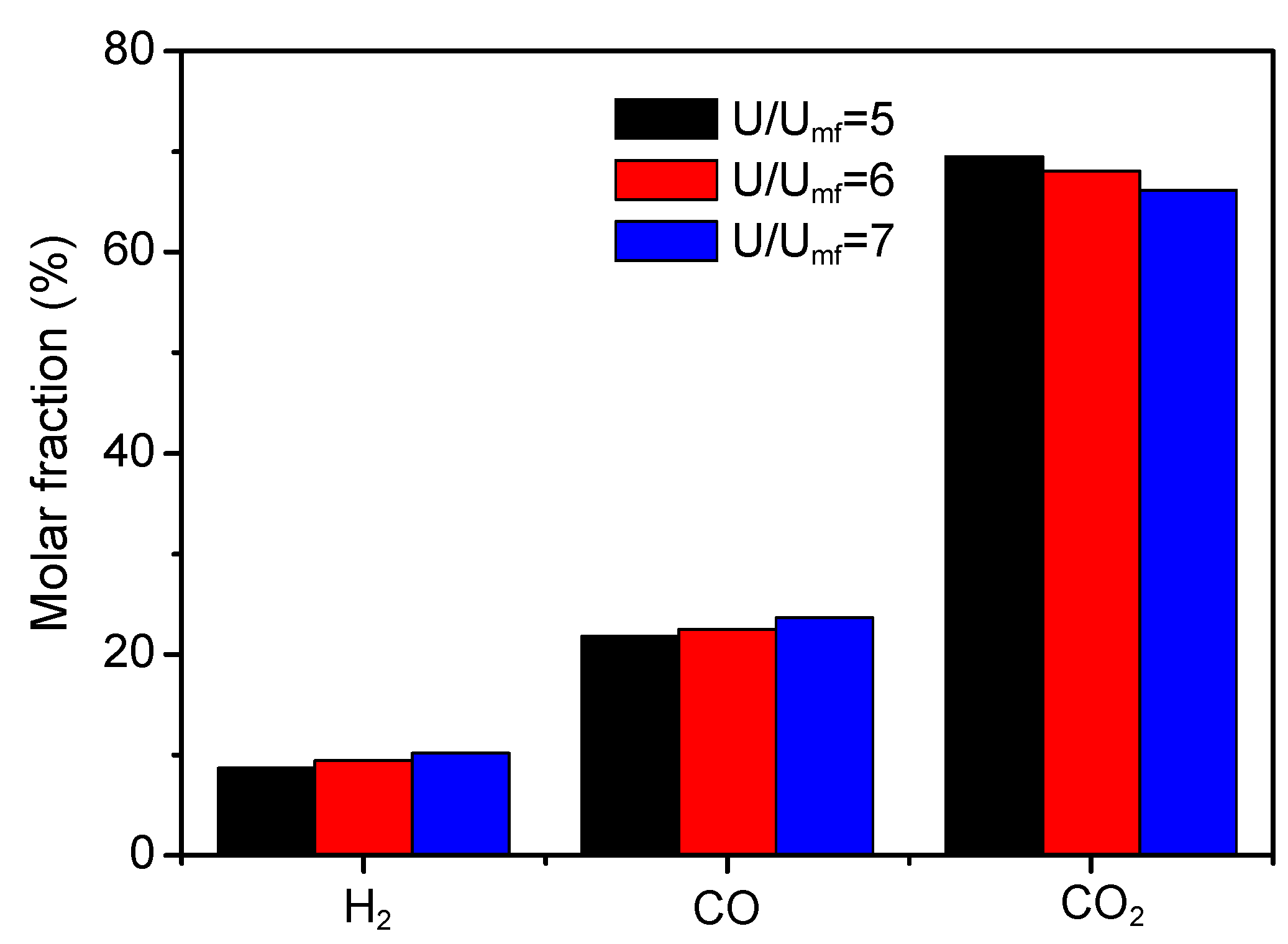
The gas stream of a fuel reactor is significant to the iG-CLC approach because it not only undertakes the task of carrying particles for flow and mixing, but also contains the reactive components for the reaction. Hence, it is very interesting to understand the effects of the gas stream (represented by the fluidizing number) on the iG-CLC performance. The fluidizing number is defined as the ratio between the superficial gas velocity U and the minimum fluidizing velocity Umf [75,76,77,78]. In this study, three different fluidizing numbers U/Umf ranging from five to seven are selected for calculation.
Figure 9 shows the comparison of the N2-excluded flue gas concentrations (dry basis) with different fluidizing numbers. It can be found that the increase of fluidizing number leads to a decline of CO2 concentration, and it is just the reverse for H2 and CO. The CO2 concentration decreases from 69.5% to 66.2% as the velocity ratio U/Umf increases from five to seven. The concentrations of H2 and CO increase from 8.7% and 21.8% to 10.2% and 23.6%, respectively. The change of gas conversions in different superficial gas velocities is mainly because of the variation in flow patterns, according to the previous literature [79]. Firstly, larger fluidizing gas velocities lead to shorter residence time of gas stream in the bed. In addition, the size of a bubble grows at a higher gas velocity, which weakens the gas–solid contact. However, similar to the observations mentioned in Section 3.4, the influence of the fluidizing number on the iG-CLC performance is much smaller than that on the gas-fueled CLC performance [61] because of the restriction from the char gasification rate.

4. Conclusions

A comprehensive three-dimensional CFD model is built to predict the char-fueled iG-CLC process in a BFB fuel reactor. The simulation results reveal the complex process mechanism of the iG-CLC approach, involving the coupling of hydrodynamics, char gasification, and chemical looping reactions of oxygen carrier, and its difference with gas-fueled CLC in terms of the adaptability to the operation conditions. The following conclusions can be drawn from this study:
(1)
In the fluidized regime, most of the intermediate products (CO and H2) from gasification are converted to CO2 and H2O by the oxygen carrier. However, the presence of bubble phase shows negative influence on the sufficient contact and reaction between gas–solid reactive components. In the freeboard region, the gas concentrations nearly keep constant because of the lack of solid phase in this region.
(2)
The N2-excluded CO2 concentration (dry basis) at the outlet for steam-char gasification over sand is 4.5%, which increases to 68.1% for iG-CLC of char. The concentrations of H2 and CO decrease from 52.3% and 43.2% to 9.4% and 22.5%, respectively. This implies that the Cu-based oxygen carrier selected is highly reactive to consume the intermediate gasification products during the iG-CLC process.
(3)
The gasification is the rate-determining step of all the reactions. In addition, the performance of the reaction is closely correlated with the flow patterns and the concentration distributions of components.
(4)
A higher CO2 concentration at the outlet can be achieved by increasing the solids inventory or decreasing the fluidizing number, which may cause the change of flow patterns such as gas residence time and bubble size. However, the effects of the solids inventory and fluidizing number on the iG-CLC performance are much smaller than those on the gas-fueled CLC because of the restriction from the front-end slow reaction of char gasification.
The results of these simulation investigations provide a deep understanding of the hydrodynamics and reaction characteristics of the iG-CLC process, which would be hard to come by under the current experimental conditions. Therefore, the present study provides important guidance for the design and application of future commercial iG-CLC power plants.

Author Contributions

Conceptualization, X.W.; supervision, B.J., Y.Z. and B.Z.; investigation, X.W.; formal analysis, X.W. and X.L.; writing—original draft preparation, X.W.; writing—review and editing, X.L. and Y.Z.

Funding

This financial supports by the National Natural Science Foundation of China (51806035), the Natural Science Foundation of Jiangsu Province (BK20170669), and the Fundamental Research Funds for the Central Universities (2242018K40117) are gratefully acknowledged.

Conflicts of Interest

The authors declare no conflict of interest.

References

  1. Abanades, J.C.; Rubin, E.S.; Anthony, E.J. Sorbent cost and performance in CO2 capture systems. Ind. Eng. Chem. Res. 2004, 43, 3462–3466. [Google Scholar] [CrossRef]
  2. Buhre, B.J.; Elliott, L.K.; Sheng, C.D.; Gupta, R.P.; Wall, T.F. Oxy-fuel combustion technology for coal-fired power generation. Prog. Energy Combust. 2005, 31, 283–307. [Google Scholar] [CrossRef]
  3. Lyngfelt, A.; Leckner, B.; Mattisson, T. A fluidized-bed combustion process with inherent CO2 separation; application of chemical-looping combustion. Chem. Eng. Sci. 2001, 56, 3101–3113. [Google Scholar] [CrossRef]
  4. Li, F.; Fan, L.S. Clean coal conversion processes–progress and challenges. Energy Environ. Sci. 2008, 1, 248–267. [Google Scholar] [CrossRef]
  5. Toftegaard, M.B.; Brix, J.; Jensen, P.A.; Glarborg, P.; Jensen, A.D. Oxy-fuel combustion of solid fuels. Prog. Energy Combust. 2010, 36, 581–625. [Google Scholar] [CrossRef]
  6. Fan, L.S.; Zeng, L.; Wang, W.; Luo, S. Chemical looping processes for CO2 capture and carbonaceous fuel conversion–prospect and opportunity. Energy Environ. Sci. 2012, 5, 7254–7280. [Google Scholar] [CrossRef]
  7. de Diego, L.F.; García-Labiano, F.; Gayán, P.; Celaya, J.; Palacios, J.M.; Adánez, J. Operation of a 10 kWth chemical-looping combustor during 200 h with a CuO–Al2O3 oxygen carrier. Fuel 2007, 86, 1036–1045. [Google Scholar] [CrossRef]
  8. Forero, C.R.; Gayán, P.; de Diego, L.F.; Abad, A.; García-Labiano, F.; Adánez, J. Syngas combustion in a 500 Wth Chemical-Looping Combustion system using an impregnated Cu-based oxygen carrier. Fuel Process. Technol. 2009, 90, 1471–1479. [Google Scholar] [CrossRef] [Green Version]
  9. Mattisson, T.; Järdnäs, A.; Lyngfelt, A. Reactivity of some metal oxides supported on alumina with alternating methane and oxygen application for chemical-looping combustion. Energy Fuels 2003, 17, 643–651. [Google Scholar] [CrossRef]
  10. Jin, H.; Ishida, M. A new type of coal gas fueled chemical-looping combustion. Fuel 2004, 83, 2411–2417. [Google Scholar] [CrossRef]
  11. Abad, A.; Mattisson, T.; Lyngfelt, A.; Rydén, M. Chemical-looping combustion in a 300W continuously operating reactor system using a manganese-based oxygen carrier. Fuel 2006, 85, 1174–1185. [Google Scholar] [CrossRef]
  12. Adánez, J.; Dueso, C.; de Diego, L.F.; García-Labiano, F.; Gayán, P.; Abad, A. Methane combustion in a 500 Wth chemical-looping combustion system using an impregnated Ni-based oxygen carrier. Energy Fuels 2008, 23, 130–142. [Google Scholar] [CrossRef]
  13. Kolbitsch, P.; Bolhàr-Nordenkampf, J.; Pröll, T.; Hofbauer, H. Operating experience with chemical looping combustion in a 120kW dual circulating fluidized bed (DCFB) unit. Int. J. Greenh. Gas Control 2010, 4, 180–185. [Google Scholar] [CrossRef]
  14. Hamers, H.P.; Gallucci, F.; Cobden, P.D.; Kimball, E.; van Sint Annaland, M. A novel reactor configuration for packed bed chemical-looping combustion of syngas. Int. J. Greenh. Gas Control 2013, 16, 1–12. [Google Scholar] [CrossRef] [Green Version]
  15. Ma, J.; Zhao, H.; Tian, X.; Wei, Y.; Zhang, Y.; Zheng, C. Continuous Operation of Interconnected Fluidized Bed Reactor for Chemical Looping Combustion of CH4 Using Hematite as Oxygen Carrier. Energy Fuels 2015, 29, 3257–3267. [Google Scholar] [CrossRef]
  16. Cao, Y.; Pan, W.P. Investigation of Chemical looping combustion by solid fuels: 1 Process analysis. Energy Fuels 2006, 20, 1836–1844. [Google Scholar] [CrossRef]
  17. Leion, H.; Mattisson, T.; Lyngfelt, A. Solid fuels in chemical-looping combustion. Int. J. Greenh. Gas Control 2008, 2, 180–193. [Google Scholar] [CrossRef]
  18. Fan, L.S.; Li, F. Chemical looping technology and its fossil energy conversion applications. Ind. Eng. Chem. Res. 2010, 49. [Google Scholar] [CrossRef]
  19. Abad, A.; Gayán, P.; de Diego, L.F.; García-Labiano, F.; Adánez, J. Fuel reactor modelling in chemical-looping combustion of coal: 1. Model formulation. Chem. Eng. Sci. 2013, 87, 277–293. [Google Scholar] [CrossRef]
  20. Cuadrat, A.; Abad, A.; Gayán, P.; de Diego, L.F.; García-Labiano, F.; Adánez, J. Theoretical approach on the CLC performance with solid fuels: Optimizing the solids inventory. Fuel 2012, 97, 536–551. [Google Scholar] [CrossRef] [Green Version]
  21. García-Labiano, F.; de Diego, L.F.; Gayán, P.; Abad, A.; Adánez, J. Fuel reactor modelling in chemical-looping combustion of coal: 2-simulation and optimization. Chem. Eng. Sci. 2013, 87, 173–182. [Google Scholar] [CrossRef]
  22. Adánez, J.; Abad, A.; Mendiara, T.; Gayán, P.; de Diego, L.F.; García-Labiano, F. Chemical looping combustion of solid fuels. Prog. Energy Combust. 2018, 65, 6–66. [Google Scholar] [CrossRef]
  23. Xiao, R.; Song, Q.; Song, M.; Lu, Z.; Zhang, S.; Shen, L. Pressurized chemical-looping combustion of coal with an iron ore-based oxygen carrier. Combust. Flame 2010, 157, 1140–1153. [Google Scholar] [CrossRef]
  24. Berguerand, N.; Lyngfelt, A. Design and operation of a 10 kWth chemical-looping combustor for solid fuels-testing with South African coal. Fuel 2008, 87, 2713–2726. [Google Scholar] [CrossRef]
  25. Berguerand, N.; Lyngfelt, A. The use of petroleum coke as fuel in a 10 kWth chemical-looping combustor. Int. J. Greenh. Gas Control 2008, 2, 169–179. [Google Scholar] [CrossRef]
  26. Shen, L.H.; Wu, J.H.; Xiao, J. Experiments on chemical looping combustion of coal with a NiO based oxygen carrier. Combust. Flame 2009, 156, 721–728. [Google Scholar] [CrossRef]
  27. Bayham, S.; McGiveron, O.; Tong, A.; Chung, E.; Kathe, M.; Wang, D.; Zeng, L.; Fan, L.S. Parametric and dynamic studies of an iron-based 25-kWth coal direct chemical looping unit using sub-bituminous coal. Appl. Energy 2015, 145, 354–363. [Google Scholar] [CrossRef]
  28. Linderholm, C.; Schmitz, M. Chemical-looping combustion of solid fuels in a 100 kW dual circulating fluidized bed system using iron ore as oxygen carrier. J. Environ. Chem. Eng. 2016, 4, 1029–1039. [Google Scholar] [CrossRef]
  29. Ma, J.; Zhao, H.; Tian, X.; Wei, Y.; Rajendran, S.; Zhang, Y.; Bhattacharya, S.; Zheng, C. Chemical looping combustion of coal in a 5 kWth interconnected fluidized bed reactor using hematite as oxygen carrier. Appl. Energy 2015, 157, 304–313. [Google Scholar] [CrossRef]
  30. Pérez-Vega, R.; Abad, A.; García-Labiano, F.; Gayán, P.; de Diego, L.F.; Adánez, J. Coal combustion in a 50 kWth Chemical Looping Combustion unit: Seeking operating conditions to maximize CO2 capture and combustion efficiency. Int. J. Greenh. Gas Control 2016, 50, 80–92. [Google Scholar] [CrossRef]
  31. Ströhle, J.; Orth, M.; Epple, B. Design and operation of a 1 MWth chemical looping plant. Appl. Energy 2014, 113, 1490–1495. [Google Scholar] [CrossRef]
  32. Thon, A.; Kramp, M.; Hartge, E.-U.; Heinrich, S.; Werther, J. Operational experience with a system of coupled fluidized beds for chemical looping combustion of solid fuels using ilmenite as oxygen carrier. Appl. Energy 2014, 118, 309–317. [Google Scholar] [CrossRef]
  33. Xiao, R.; Chen, L.; Saha, C.; Zhang, S.; Bhattacharya, S. Pressurized chemical-looping combustion of coal using an iron ore as oxygen carrier in a pilot-scale unit. Int. J. Greenh. Gas Control 2012, 10, 363–373. [Google Scholar] [CrossRef]
  34. Wang, X.; Jin, B.; Zhu, X.; Liu, H. Experimental Evaluation of a Novel 20 kWth in Situ Gasification Chemical Looping Combustion Unit with an Iron Ore as the Oxygen Carrier. Ind. Eng. Chem. Res. 2016, 55, 11775–11784. [Google Scholar] [CrossRef]
  35. Cheng, M.; Sun, H.; Li, Z.; Cai, N. Annular carbon stripper for chemical-looping combustion of coal. Ind. Eng. Chem. Res. 2017, 56, 1580–1593. [Google Scholar] [CrossRef]
  36. Wang, P.; Means, N.; Howard, B.H.; Shekhawat, D.; Berry, D. The reactivity of CuO oxygen carrier and coal in Chemical-Looping with Oxygen Uncoupled (CLOU) and In-situ Gasification Chemical-Looping Combustion (iG-CLC). Fuel 2018, 217, 642–649. [Google Scholar] [CrossRef]
  37. Fan, L.S. Chemical Looping Systems for Fossil Energy Conversions; John Wiley & Sons: Hoboken, NJ, USA, 2011. [Google Scholar]
  38. Adamczyk, W.P.; Bialecki, R.A.; Ditaranto, M.; Gladysz, P.; Haugen, N.E.L.; Katelbach-Wozniak, A.; Klimanek, A.; Sladek, S.; Szlek, A.; Wecel, G. CFD modeling and thermodynamic analysis of a concept of a MILD-OXY combustion large scale pulverized coal boiler. Energy 2017, 140, 1305–1315. [Google Scholar] [CrossRef]
  39. Liu, B.; Papadikis, K.; Gu, S.; Fidalgo, B.; Longhurst, P.; Li, Z.; Kolios, A. CFD modelling of particle shrinkage in a fluidized bed for biomass fast pyrolysis with quadrature method of moment. Fuel Process. Technol. 2017, 164, 51–68. [Google Scholar] [CrossRef] [Green Version]
  40. Wu, Y.; Liu, D.; Duan, L.; Ma, J.; Xiong, J.; Chen, X. Three-dimensional CFD simulation of oxy-fuel combustion in a circulating fluidized bed with warm flue gas recycle. Fuel 2018, 216, 596–611. [Google Scholar] [CrossRef]
  41. Nam, H.; Rodriguez-Alejandro, D.A.; Adhikari, S.; Brodbeck, C.; Taylor, S.; Johnson, J. Experimental investigation of hardwood air gasification in a pilot scale bubbling fluidized bed reactor and CFD simulation of jet/grid and pressure conditions. Energy Convers. Manag. 2018, 168, 599–610. [Google Scholar] [CrossRef]
  42. Deng, Z.G.; Xiao, R.; Jin, B.S.; Song, Q.L.; Huang, H. Multiphase CFD modeling for a chemical looping combustion process (fuel reactor). Chem. Eng. Technol. 2008, 31, 1754–1766. [Google Scholar] [CrossRef]
  43. Jung, J.; Gamwo, I. Multiphase CFD-based models for chemical looping combustion process: Fuel reactor modeling. Powder Technol. 2008, 183, 401–409. [Google Scholar] [CrossRef]
  44. Jin, B.; Xiao, R.; Deng, Z.; Song, Q. Computational fluid dynamics modeling of chemical looping combustion process with calcium sulphate oxygen carrier. Int. J. Chem. React. Eng. 2009, 7. [Google Scholar] [CrossRef]
  45. Kruggel-Emden, H.; Rickelt, S.; Stepanek, F.; Munjiza, A. Development and testing of an interconnected multiphase CFD-model for chemical looping combustion. Chem. Eng. Sci. 2010, 65, 4732–4745. [Google Scholar] [CrossRef]
  46. Mahalatkar, K.; Kuhlman, J.; Huckaby, E.D.; O’brien, T. Simulations of a circulating fluidized bed chemical looping combustion system utilizing gaseous fuel. Oil Gas Sci. Technol. 2011, 66, 301–311. [Google Scholar] [CrossRef]
  47. Kruggel-Emden, H.; Stepanek, F.; Munjiza, A. A study on the role of reaction modeling in multi-phase CFD-based simulations of chemical looping combustion. Oil Gas Sci. Technol. 2011, 66, 313–331. [Google Scholar] [CrossRef]
  48. Harichandan, A.B.; Shamim, T. CFD analysis of bubble hydrodynamics in a fuel reactor for a hydrogen-fueled chemical looping combustion system. Energy Convers. Manag. 2014, 86, 1010–1022. [Google Scholar] [CrossRef]
  49. Wang, S.; Lu, H.; Zhao, F.; Liu, G. CFD studies of dual circulating fluidized bed reactors for chemical looping combustion processes. Chem. Eng. J. 2014, 236, 121–130. [Google Scholar] [CrossRef]
  50. Wang, S.; Chen, J.; Lu, H.; Liu, G.; Sun, L. Multi-scale simulation of chemical looping combustion in dual circulating fluidized bed. Appl. Energy 2015, 155, 719–727. [Google Scholar] [CrossRef]
  51. Banerjee, S.; Agarwal, R. Transient reacting flow simulation of spouted fluidized bed for coal-direct chemical looping combustion with different Fe-based oxygen carriers. Appl. Energy 2015, 160, 552–560. [Google Scholar] [CrossRef]
  52. Zhang, Y.; Chao, Z.; Jakobsen, H.A. Modelling and simulation of chemical looping combustion process in a double loop circulating fluidized bed reactor. Chem. Eng. J. 2017, 320, 271–282. [Google Scholar] [CrossRef] [Green Version]
  53. Zhang, Z.; Zhou, L.; Agarwal, R. Transient simulations of spouted fluidized bed for coal-direct chemical looping combustion. Energy Fuels 2014, 28, 1548–1560. [Google Scholar] [CrossRef]
  54. Guan, Y.; Chang, J.; Zhang, K.; Wang, B.; Sun, Q. Three-dimensional CFD simulation of hydrodynamics in an interconnected fluidized bed for chemical looping combustion. Powder Technol. 2014, 268, 316–328. [Google Scholar] [CrossRef]
  55. Peng, Z.; Doroodchi, E.; Alghamdi, Y.A.; Shah, K.; Luo, C.; Moghtaderi, B. CFD–DEM simulation of solid circulation rate in the cold flow model of chemical looping systems. Chem. Eng. Res. Des. 2015, 95, 262–280. [Google Scholar] [CrossRef]
  56. Geng, C.; Zhong, W.; Shao, Y.; Chen, D.; Jin, B. Computational study of solid circulation in chemical-looping combustion reactor model. Powder Technol. 2015, 276, 144–155. [Google Scholar] [CrossRef]
  57. Mahalatkar, K.; Kuhlman, J.; Huckaby, E.D.; O’Brien, T. CFD simulation of a chemical-looping fuel reactor utilizing solid fuel. Chem. Eng. Sci. 2011, 66, 3617–3627. [Google Scholar] [CrossRef]
  58. Su, M.; Zhao, H.; Ma, J. Computational fluid dynamics simulation for chemical looping combustion of coal in a dual circulation fluidized bed. Energy Convers. Manag. 2015, 105, 1–12. [Google Scholar] [CrossRef]
  59. Sharma, R.; May, J.; Alobaid, F.; Ohlemueller, P.; Stroehle, J.; Epple, B. Euler-Euler CFD simulation of the fuel reactor of a 1 MWth chemical-looping pilot plant: Influence of the drag models and specularity coefficient. Fuel 2017, 200, 435–446. [Google Scholar] [CrossRef]
  60. May, J.; Alobaid, F.; Ohlemüller, P.; Stroh, A.; Ströhle, J.; Epple, B. Reactive two–fluid model for chemical–looping combustion–Simulation of fuel and air reactors. Int. J. Greenh. Gas Control 2018, 76, 175–192. [Google Scholar] [CrossRef]
  61. Wang, X.; Jin, B.; Zhong, W.; Zhang, Y.; Song, M. Three-dimensional simulation of a coal gas fueled chemical looping combustion process. Int. J. Greenh. Gas Control 2011, 5, 1498–1506. [Google Scholar] [CrossRef]
  62. Wang, X.; Jin, B.; Zhang, Y.; Zhong, W.; Yin, S. Multiphase computational fluid dynamics (CFD) modeling of chemical looping combustion using a CuO/Al2O3 oxygen carrier: effect of operating conditions on coal gas combustion. Energy Fuels 2011, 25, 3815–3824. [Google Scholar] [CrossRef]
  63. Wang, X.; Jin, B.; Zhang, Y.; Zhang, Y.; Liu, X. Three dimensional modeling of a coal-fired chemical looping combustion process in the circulating fluidized bed fuel reactor. Energy Fuels 2013, 27, 2173–2184. [Google Scholar] [CrossRef]
  64. Wang, X.; Jin, B.; Liu, H.; Zhang, B.; Zhang, Y. Prediction of In-Situ Gasification Chemical Looping Combustion Effects of Operating Conditions. Catalysts 2018, 8, 526. [Google Scholar] [CrossRef]
  65. Wang, X.; Shao, Y.; Jin, B.; Zhang, Y. Three-dimensional multiphase full-loop simulation of directional separation of binary particle mixtures in high-flux coal-direct chemical-looping combustion system. Particuology 2019. [Google Scholar] [CrossRef]
  66. Gordillo, E.D.; Belghit, A. A two phase model of high temperature steam-only gasification of biomass char in bubbling fluidized bed reactors using nuclear heat. Int. J. Hydrogen Energy 2011, 36, 374–381. [Google Scholar] [CrossRef]
  67. Jin, B.; Wang, X.; Zhong, W.; Tao, H.; Ren, B.; Xiao, R. Modeling on high-flux circulating fluidized bed with Geldart group B particles by kinetic theory of granular flow. Energy Fuels 2010, 24, 3159–3172. [Google Scholar] [CrossRef]
  68. Benyahia, S.; Syamlal, M.; O’Brien, T.J. Study of the ability of multiphase continuum models to predict core-annulus flow. AIChE J. 2007, 53, 2549–2568. [Google Scholar] [CrossRef]
  69. Ding, J.; Gidaspow, D. A bubbling fluidization model using kinetic theory of granular flow. AIChE J. 1990, 36, 523–538. [Google Scholar] [CrossRef]
  70. Gidaspow, D.; Bezburuah, R.; Ding, J. Hydrodynamics of circulating fluidized beds: Kinetic theory approach. In Proceedings of the 7th Engineering Foundation Conference on Fluidization, Brisbane, Australia, 3–8 May 1992. [Google Scholar]
  71. Umeki, K.; Yamamoto, K.; Namioka, T.; Yoshikawa, K. High temperature steam-only gasification of woody biomass. Appl. Energy 2010, 87, 791–798. [Google Scholar] [CrossRef]
  72. Abad, A.; Adánez, J.; García-Labiano, F.; de Diego, L.F.; Gayán, P. Modeling of the chemical-looping combustion of methane using a Cu-based oxygen-carrier. Combust. Flame 2010, 157, 602–615. [Google Scholar] [CrossRef] [Green Version]
  73. Lim, C.N.; Gilbertson, M.A.; Harrison, A.J.L. Bubble distribution and behaviour in bubbling fluidised beds. Chem. Eng. Sci. 2007, 62, 56–69. [Google Scholar] [CrossRef]
  74. Scott, S.A.; Dennis, J.S.; Hayhurst, A.N.; Brown, T. In situ gasification of a solid fuel and CO2 separation using chemical looping. AIChE J. 2006, 52, 3325–3328. [Google Scholar] [CrossRef]
  75. Cheng, L.; Basu, P. Effect of pressure on loop seal operation for a pressurized circulating fluidized bed. Powder Technol. 1999, 103, 203–211. [Google Scholar] [CrossRef]
  76. Kim, S.W.; Kim, S.D. Effects of particle properties on solids recycle in loop-seal of a circulating fluidized bed. Powder Technol. 2002, 124, 76–84. [Google Scholar] [CrossRef]
  77. Wang, X.; Jin, B.; Liu, X.; Zhang, Y.; Liu, H. Experimental investigation on flow behaviors in a novel in situ gasification chemical looping combustion apparatus. Ind. Eng. Chem. Res. 2013, 52, 14208–14218. [Google Scholar] [CrossRef]
  78. Wang, X.; Jin, B.; Liu, H.; Wang, W.; Liu, X.; Zhang, Y. Optimization of in situ gasification chemical looping combustion through experimental investigations with a cold experimental system. Ind. Eng. Chem. Res. 2015, 54, 5749–5758. [Google Scholar] [CrossRef]
  79. Chen, X.Z.; Shi, D.P.; Gao, X.; Luo, Z.H. A fundamental CFD study of the gas–solid flow field in fluidized bed polymerization reactors. Powder Technol. 2011, 205, 276–288. [Google Scholar] [CrossRef]
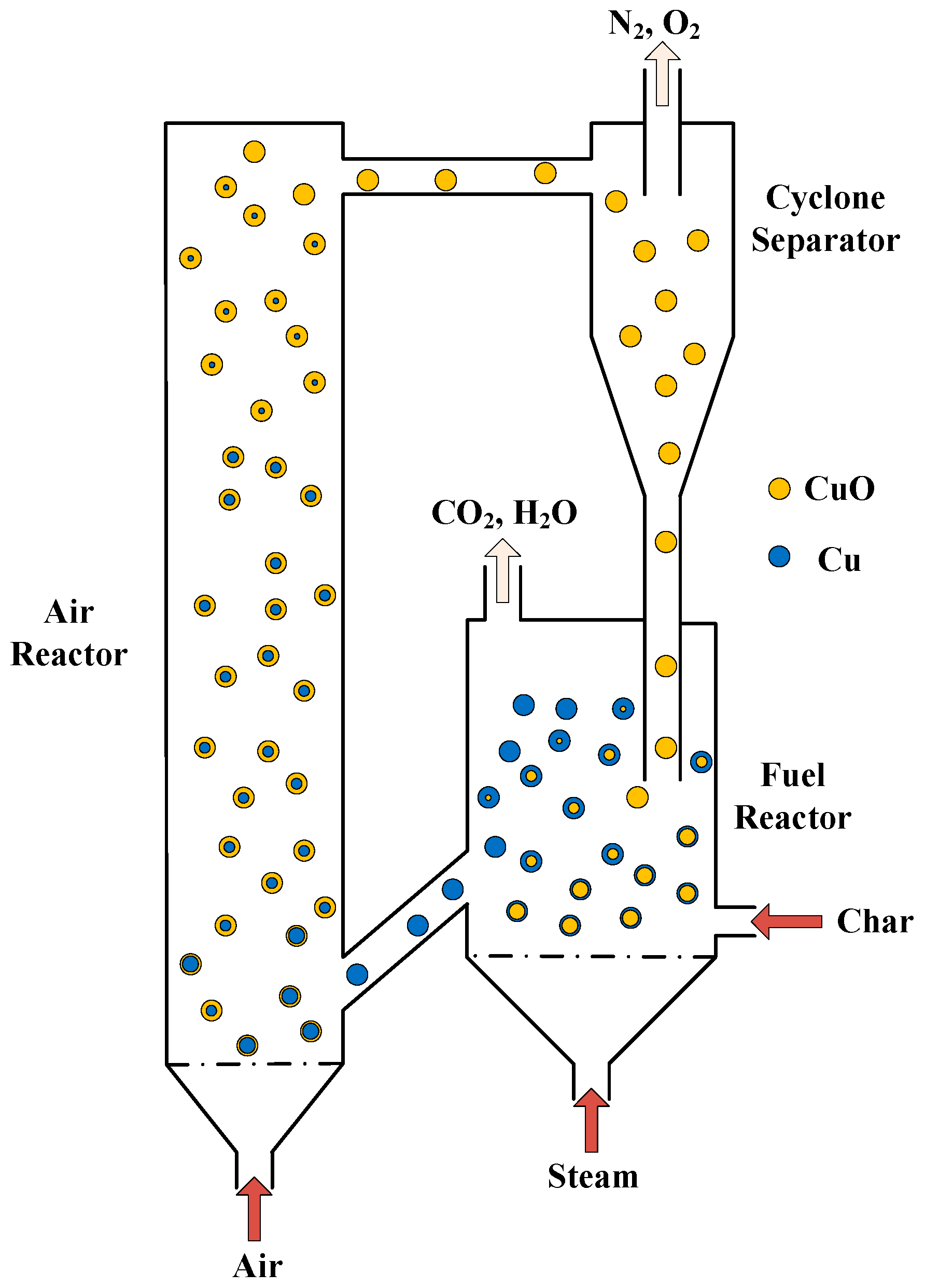
Figure 1. Schematic diagram of a conventional solid-fueled CLC system.
Processes 07 00603 g001
Figure 2. Geometry and mesh model of the BFB fuel reactor.
Processes 07 00603 g002
Figure 3. Axial (x = 0) distributions of flow patterns and gas–solid concentrations. (a) Solids holdup; (b) CO2 molar fraction in gas phase; (c) H2O molar fraction in gas phase; (d) Char mass fraction in solid phase.
Processes 07 00603 g003
Figure 4. Variations of the gas molar fractions with time at the fuel reactor outlet.
Processes 07 00603 g004
Figure 5. Comparison of the computed exhaust concentrations from steam-char gasification reaction over sand with the previous data: T0 = 1173 K, U/Umf = 4.5.
Processes 07 00603 g005
Figure 6. Comparison of N2-excluded flue gas concentrations (dry basis). (a) Gas concentrations for gasification over sand at the outlet; (b) Gas concentrations for iG-CLC at the outlet.
Processes 07 00603 g006
Figure 7. Distributions of heterogeneous reaction rates (Hb = 1.1 m, Qc = 1.6 kg/h, U/Umf = 6, Tb = 1073 K). (a) C(s)-H2O rate; (b) C(s)-CO2 rate; (c) CuO(s)-CO rate; (d) CuO(s)-H2 rate.
Processes 07 00603 g007
Figure 8. Distributions of N2-excluded flue gas concentrations (dry basis) in different solids inventories.
Processes 07 00603 g008
Figure 9. Distributions of N2-excluded flue gas concentrations (dry basis) in different fluidizing numbers.
Processes 07 00603 g009
Table 1. Rate parameters of the heterogeneous reactions occurred in the fuel reactor.
No.Reaction Rate Constant kReaction Rate rReference
1 k 1 = 2.07 × 10 4 exp ( 22000 / R T ) r 1 = k 1 P H 2 O 0.73 [71]
2 k 2 = 1.12 × 10 5 exp ( 245000 / R T ) r 2 = k 2 P C O 2 0.31 [71]
3 k 3 = 2.842 × 10 2 exp ( 3961.5 / R T ) r 3 = k 3 ( Y C O Y H 2 O Y C O 2 Y H 2 / K 3 e q ) [66]
4 k 4 = 1.54 × 10 3 exp ( 20000 / R T ) r 4 = k 4 C H 2 0.5 α p Y C u O / r g , C u O [7]
5 k 5 = 2.21 × 10 4 exp ( 11000 / R T ) r 5 = k 5 C C O 0.8 α p Y C u O / r g , C u O [7]
Table 2. Model parameters and initial conditions applied to the simulations.
DescriptionUnitValue
Reactor diameter m0.22
Reactor height m2
Mean particle density kg/m31560
Mean particle diameter mm0.5
Initial volume fraction of solid phase-0.55
Maximum packing of solid phase-0.64
Initial bed heightm1.1
Char feed rate kg/h1.6
Inlet steam temperatureK1073
Fluidizing number-6
Inlet boundary condition-velocity-inlet
Outlet boundary condition-outflow
Time step sizes10−4
Convergence criteria-10−4