Abstract
Argon stirring is one of the most widely used metallurgical methods in the secondary refining process as it is economical and easy, and also an important refining method in clean steel production. Aiming at the issue of poor homogeneity of composition and temperature of a bottom argon blowing ladle molten steel in a Chinese steel mill, a 1:5 water model for 110 t ladle was established, and the mixing time and interface slag entrainment under the different conditions of injection modes, flow rates and top slag thicknesses were investigated. The flow dynamics of argon plume in steel ladle was also discussed. The results show that, as the bottom blowing argon flow rate increases, the mixing time of ladle decreases; the depth of slag entrapment increases with the argon flow rate and slag thickness; the area of slag eyes decreases with the decrease of the argon flow rate and increase of slag thickness. The optimum argon flow rate is between 36–42 m3/h, and the double porous plugs injection mode should be adopted at this time.
1. Introduction
The major tasks in the production of clean quality steel include the removing of inclusions and unwanted impurities, the secondary refining process is the important step of cleansing molten steel, and argon bottom blowing is one of the most popular ladle metallurgical methods in all types of ladle metallurgy processes as it is economical and easy [1]. During the argon bottom blowing, the molten steel homogenization and entrapment of the top slag have a great effect on the result of the ladle metallurgy. The water model [2,3,4,5,6] and mathematical models [7,8,9] are often used to simulate metal bath in the ladle during the argon bottom blowing, as the flow field in the ladle can be observed in the laboratory without the interfering of high temperature molten steel, splashing and dust in the actual teeming ladle. Some researchers found that eccentric bottom blowing is in favor of bath mixing in the ladle [7,10]. Some investigators also found that the position of porous plugs, gas flow rate and the size of ladle have an abundant influence on bath mixing in the ladle [4,5,11,12,13,14,15,16,17]. It was discovered that the top slag layer could consume some part of kinetic energy of flow and enlarge the mixing time of the ladle [18,19,20,21,22]. Some researchers studied the flow field and inclusion removal in the ladle during argon blowing by studying the bubble motion in the process of argon stirring [23,24]. The results of Luis E. Jardón-Pérez’s research show that the ladle must be operated using a differentiated flow ratio for optimal performance [25]. With the help of the water model the argon bottom-blowing was improved dramatically. However, as the shortening of mixing time and decreasing top slag entrapment are a pair of contradictions during the argon bottom-blowing, the more reasonable and general compromise method should be studied based on the study of the detailed data of flow field in the metal bath of the ladle with the water model.
In this paper, based on the experiment of the water model, the bottom-blowing ladle of a Chinese steel mill was studied, and the effect of the layout of porous plug, argon flow rate and properties of top slag to ladle stirring efficiency, level fluctuation and slag entrapment. Based on the results, the operation of bottom-blowing of the ladle was improved.
2. Water Model
In order to uniform the composition and temperature of metal bath in the ladle, a 1:5 downscale water model was established, with the geometrical similarity of the actual ladle in a Chinese steel mill. Water and air were chosen to simulate molten steel and argon, the dimension data of the water model and prototype were shown in Table 1, and a schematic diagram of the prototype was in Figure 1.

Table 1.
The dimension data of the water model and prototype.
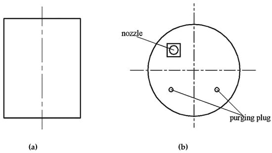
Figure 1.
Schematic diagram of the ladle prototype; (a) vertical section; (b) porous plug arrangement.
The major forces affecting the flow of molten steel in the ladle include float force, viscous force and gravity. According to similarity rules, modified Freud number can characterize the kinetic similarity of the argon blowing system in the ladle with bottom blowing of argon. In our study work, the water model should have the same modified Freud number as the prototype, as Equation (1):
That is,
where, ρair, ρwater, ρAr, ρsteel are the densities of air, water, argon and molten steel respectively, kg/m3; g is the acceleration of gravity, m/s2; uwater, usteel are the characteristic velocities of air and argon respectively, m/s; H is the height of steel bath in the ladle, m.
The characteristic velocity u can be expressed with Equation (3):
where, Q is the gas flow rate, m3/h; d is the equivalent diameter of the porous plug, m.
Based on the data of Table 1, Equations (2) and (3), the relation between gas flow rates in the water model and in the actual teeming ladle, i.e., Qm and Qp, was derived as Equation (4).
According to the range of flow rate of argon blown in the prototype ladle, that is 12–50 m3/h, the air flow rates were calculated from Equation (4) and listed in Table 2.

Table 2.
The flow rate of bottom gas in the water model and prototype ladle.
As the flow behaviour of molten steel-slag was influenced by interfacial tension of molten steel and slag, the weber numbers of the model should be equivalent to that of the prototype to insure the kinetic similarity at the interface between the molten steel and slag, Equation (5).
That is,
where, σwater-oil is the interfacial tension between the water and oil, N/m; σseel-slag is the interfacial tension between the steel and slag, N/m.
In the water model experiment, aviation kerosene and vacuum pump oil were mixed in a certain proportion to obtain a mixture oil with the same kinematic viscosity of the top slag.
The slag layer thickness of the prototype ladle is 60–100 mm, and the oil layer thickness (OLT) in the water model experiment is 12–20 mm according to the similarity ratio of 1:5. Five oil layer thicknesses were selected in the experiment, as shown in Table 3, to study the effect of the slag layer thickness to level fluctuation and slag entrapment of steel bath in the ladle.

Table 3.
The thicknesses of the top oil layer.
There were two methods of eccentric bottom blowing in the prototype ladle: One is a single porous plug with eccentric distance of 0.6 R, in which the eccentric distance is the distance between the centers of the porous plug and ladle; the other is a double porous plug with an intersection angle of 100° and eccentric distance of 0.6 R.
The schematic diagram of the water model experiment setup was shown in Figure 2. In the experiments, the mixing time of the model was measured through the stimulus-response method with a tracer of KCl solution, flow field, level fluctuation and slag entrapment of steel bath in the model ladle was recorded by high speed digital camera.
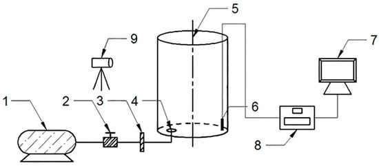
Figure 2.
Water model experiment setup: (1) Air compressor; (2) pressure gauge; (3) air flow rate controller; (4) porous plug; (5) model ladle; (6) conductivity probe; (7) computer; (8) conductivity meter; (9) high speed digital camera.
3. Results and Discussion
3.1. Mixing Time
In the water model experiment, seven air flow rates, that is 0.095, 0.143, 0.191, 0.238, 0.286, 0.333, 0.381 m3/h, were used to bottom-blow into the model ladle with/without an oil layer covered through single or double porous plugs.
The influences of the bottom air flow rate, slag layer and the number of porous plugs to the mixing time were shown in Figure 3.
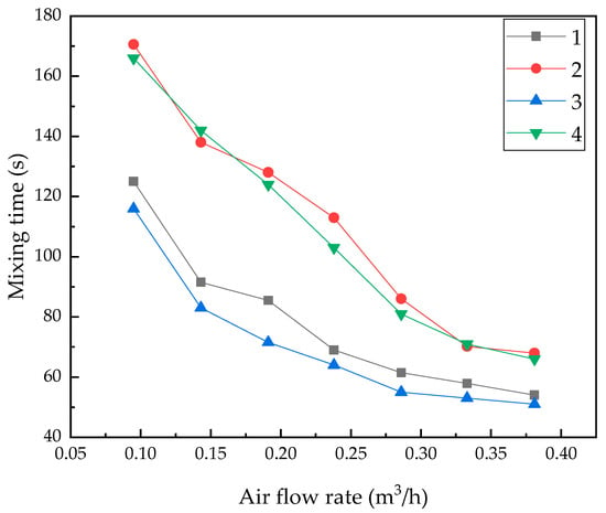
Figure 3.
The relation between mixing time and air flow rate in the ladle with single porous plug and double porous plugs: (1) Single porous plug without oil layer; (2) single porous plug with 16 mm OLT; (3) double porous plugs without oil layer; (4) double porous plugs with 16 mm OLT.
From Figure 3, it was found that as the increase of the bottom air flow rate, the mixing time of the metal bath in ladle decreased. When the bottom blowing air flow rate was equal to 0.095 m3/h (corresponding 12 m3/h in prototype), the mixing time of the steel bath was relatively long, as stirring power produced by the dispersing small bubbles from porous plugs was too small and the circulating flow rate in steel bath was weak.
As the bottom blowing air flow rate was increased from 0.143 m3/h to 0.286 m3/h (corresponding from 18 m3/h to 36 m3/h in the prototype), the mixing time was reduced abundantly. When the bottom air flow rate was above 0.143 m3/h, the bubble group in water model was transferred from dispersing small bubbles to spherical bubbles or coronal bubbles group. The stirring energy by the bubble group increased abundantly, so was the circulating flow in the steel bath of the ladle, which decreased the mixing time markedly.
When the bottom blowing flow rate increased above 0.286 m3/h, the mixing time of the steel bath increased slowly with the bottom blowing flow rate. The reason was that when the flow rate exceeds 0.286 m3/h, the diameter of the plume caused by bubble groups did not increase further, more bubbles were blown into the plume, bubble coalescence and breaking were more frequent, and more energy was exhausted in bubble coalescence and breaking, instead of driving circulate flow in the bath. At the same time, there were more energy consumed by the surface rise and splashing, which were caused by the escaping of a large number of bubbles. Therefore, when the bottom blowing flow rate increased above 0.286 m3/h (i.e., 36 m3/h in prototype), the increase of the bottom blowing gas flow rate could not improve the mixing of the bath in the ladle, and there was an obvious inflection point on the mixing time curve.
The slag layer could influence the mixing time, Figure 3. It was shown that at the same bottom blowing flow rate, the mixing time without the oil layer was obviously shorter than the mixing time with OLT of 16 mm. The reason was that the horizontal flow at the surface was obstructed by the slag layer at the bath top, so was the circulating flow in the bath. It can also be seen from the figure that the air flow rate at mixing time inflection without the oil layer in the ladle was 0.286 m3/h, and the air flow rate at mixing time inflection point with the oil layer in the ladle was 0.333 m3/h.
As there were two plumes in the ladle with double porous plugs, the intersection area of bubble columns doubled, and the mixing of the bath improved obviously. From Figure 3, it was found that the mixing time of the bath in the ladle with double porous plugs shortened abundantly.
The relation between the mixing time and bottom blowing flow rate in the ladle with double porous plugs was shown in Figure 4. It was found that with the increase of the bottom gas flow rate, the mixing time of the bath in the ladle was decreased. When the flow rate is above 0.333 m3/h (i.e., 42 m3/h in prototype), the mixing time was reduced slowly as the increase of the flow rate, and the trend was similar to the ladle with a single porous plug. The slag layer obstructed the mixing in the ladle with double porous plugs, as the work by viscous force at the surface of the bath in the ladle consumed the kinetic energy of plumes driven by bubbles blown from double porous plugs. The thickness of the slag layer had a large influence to the mixing time of the bath in the ladle, as the mixing time of the bath in the ladle decreased with the increase of thickness of the slag layer.
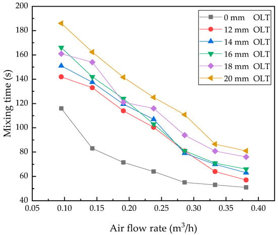
Figure 4.
The relation of mixing time and air flow rate in the ladle with double porous plugs.
In summary, for the actual operation of the prototype ladle, the best option of the bottom gas flow rate was 36–42 m3/h for the ladle. When the bottom flow rate in the actual ladle increased above that range, the mixing time could not be reduced effectively.
3.2. The Entrapment of Slag in Ladle
For the entrapment of the top slag in the ladle, the influence of the bottom gas flow rate, number of porous plugs and thickness of the slag layer to the top slag entrapment in the ladle was studied with an image processing method in the water model.
3.2.1. The Entrapment of Slag in Ladle with Single Porous Plug
In the water model, the entrapment of the top slag during bottom blowing was videoed to analyse the influence of the bottom gas flow rate to entrapment, Figure 5, and in the experiment the thickness of oil (simulating the slag layer) was 14 mm. It was found that as the bottom blowing gas flow rate was less than 0.143 m3/h, the fluctuation at the interface between the oil and water was gentle (Figure 5a,b), the escape of bubbles caused the little disturb at the interface between the oil and water and the horizontal flow at the interface driven by the upper flow around the bubble column caused the oil layer thickening at the area around the bubble escaping region. As the bottom flow rate was increased above 0.143 m3/h, the escape of bubbles caused the obvious disturb at the interface between the oil and water, the horizontal flow at the interface caused the oil layer obviously thickening at the area around the bubble escaping region, as shown in Figure 5c–f, the oil bump was formed at that area, the shear of horizontal flow resulted in the small droplet divided from the oil bump and the entrapment was formed, most of the oil droplets were soon floated up to the top oil layer. When the bottom gas flow rate was above 0.333 m3/h (Figure 5g,h), the entrapment worsened, most of the oil droplets were not floated up to the top oil layer, instead, they were dragged into the deep region in the water model by the downward flow.
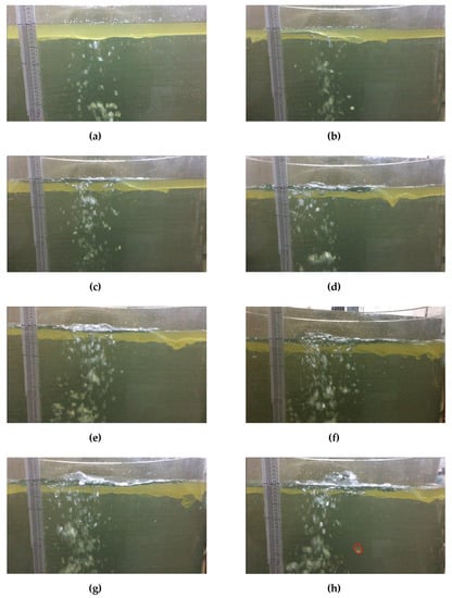
Figure 5.
The influence of the air flow rate to the entrapment in the water model simulating the ladle with a single porous plug and OLT of 14 mm: (a) Q = 0.0475 m3/h; (b) Q = 0.095 m3/h; (c) Q = 0.143 m3/h; (d) Q = 0.191 m3/h; (e) Q = 0.238 m3/h; (f) Q = 0.286 m3/h; (g) Q = 0.333 m3/h; (h) Q = 0.381 m3/h.
The area without the slag covering, which was caused by the bubbles-escaping at the top of the bath, was called the slag eye. The area of the slag eye in the water model with a single porous plug at different bottom gas flow rates and slag thicknesses was summarized in Table 4, which was measured from the digital image of the top of the water model during bottom blowing. From Table 4, it was found that the area of the slag eye increased as the increase of the bottom gas flow rate. The reason was that as the bottom gas flow rate increased, the rise velocity of the plume increased and then the horizontal velocity at the liquid-oil interface was also raised, the increase of the horizontal velocity raised the repulsive force at the interface between the water and oil and the area of the slag eye increased. On the other hand, as the raise of the top oil thickness, the work to repulsive the oil at the top of the water model, which overcame the interfacial tension and viscous force, increased and the area of the slag eye decreased at the same bottom gas flow rate.

Table 4.
The areas of the slag eye at different air flow rate and oil thickness in the water model with a single porous plug.
Figure 6 showed the relation between entrapping the depth of the top oil in the water model with a single porous plug, bottom flow rate and oil thickness. It was shown that at the same bottom flow rate the entrapping depth increased as the increase of oil thickness, and at the same oil thickness the entrapping depth increased as the bottom flow rate, but when the bottom flow rate was above a certain level, the entrapping depth would not increase as the increase of the flow rate. The reason was that as the bottom flow rate increased, more of the oil layer at the top of the water model was repulsed from the bubble escaping region of the plume, the horizontal velocity of water increased, the velocity of the downward flow around the plume also increased, the bump of the oil layer increased, Figure 5, the shear forced on the bump of the oil layer increased, and all these factors caused oil entrapping in the water model raising. From Figure 6, the critical bottom flow rates for oil entrapment in the water model were in the range of 0.095–0.143 m3/h (18–24 m3/h for prototype ladle).
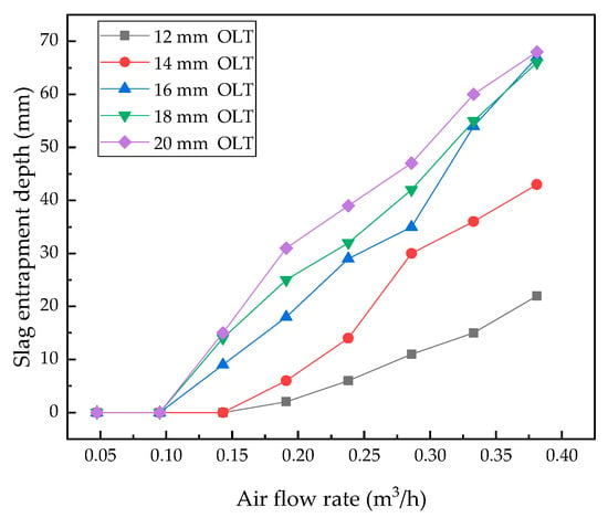
Figure 6.
The influence of air flow rate to entrapping depth in the water model with a single porous plug.
3.2.2. The Entrapment of Slag in Ladle with Double Porous Plugs
The entrapment of the slag in the ladle with double porous plugs was shown in Figure 7. For the water model with double porous plugs, the region between the porous plugs and the adjoining wall of the water model was signed as Region A, and the region between the two porous plugs was signed as Region B, as shown in Figure 8a. At Region A, the flow of water was similar to that of the water model with a single porous plug. However at Region B, the oil layer was pushed by the flows of counter directions from the two porous plugs, the bump of the oil layer was higher than that in the water model with a single porous plug, and the shear from the horizontal flow was stronger intensively, as shown in Figure 7. The plumes from the two porous plugs caused the vortex at Region B. So, there was oil entrapped into the vortex, which was called as vortex entrapment.
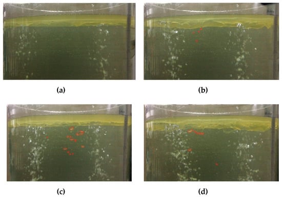
Figure 7.
Entrapment in the water model at a different bottom flow rate (16 mm OLT): (a) Q = 0.095 m3/h; (b) Q = 0.191 m3/h; (c) Q = 0.286 m3/h; (d) Q = 0.381 m3/h.
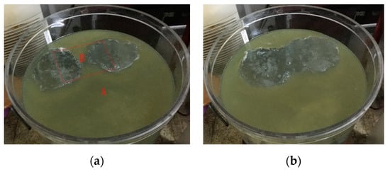
Figure 8.
The slag eyes in the water model with double porous plugs (16 mm OLT): (a) Q = 0.286 m3/h, (b) Q = 0.381 m3/h.
For the slag eye, when the bottom flow rate was small, there were two slag eyes formed at the top of the water model. When the bottom flow rate was large, the two slag eyes were merged and formed the goggle type slag eye, Figure 8. When the goggle type slag eye was formed, there was no slag floated at the Region B, Region A was the only region with slag entrapment.
Table 5 showed the areas of slag eyes at different flow rate and oil thickness. With the increase of the bottom flow rate the area of slag eyes increased for the same oil layer thickness, and with the oil layer thickness increasing the area of slag eyes decreased in the water model with double porous plugs, the trend of which was just like that in the water model with a single porous plug. Compared with Table 4, the slag eye is easier to form in the double porous plugs ladle, and the area of the slag eye is usually larger than that in a single porous plug ladle.

Table 5.
The areas of the slag eye at a different bottom flow rate and top oil thickness in the water model with a double porous plug.
As the increase of the bottom flow rate, the entrapping depth increased in the water model with double porous plugs, shown in Figure 9, the trend of which was similar to that in the water model with a single porous plug. In the water model with double porous plugs, the critical bottom flow rate causing entrapment was 0.095 m3/h (12 m3/h for prototype ladle). Compared with Figure 6, it was found that the entrapping depth was higher obviously in the water model with double porous plugs, because there was vortex entrapment formed in Region B.
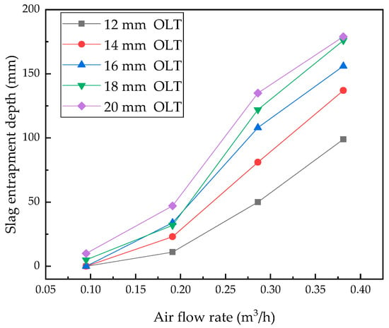
Figure 9.
The influence of a double porous plug bottom flow rate to entrapping depth in the water model.
3.3. Comprehensive Analysis of Mixing and Slag Entrapment
The results of mixing time show that the optimum gas flow rate for the prototype ladle is 36–42 m3/h, the ladle with double porous plugs should be selected at the same time. Slag thickness has a significant influence on the entrapping depth of the slag and slag eye area. In actual production, slag entrapment is beneficial to improve the refining effect, therefore, more consideration should be given to the area of the slag eye and bath mixing.
The bubble motion in the water model experiment was shown in Figure 10. Bubble motion is accompanied by the process of coalescence, collapse and re-coalescence. In the process of bubble floating up, the size and shape of the bubble have changed. When the diameter of the bubble exceeds 1 cm, the shape of the bubble changes into a spherical corona. In low viscosity liquids, the rising velocity of the spherical coronal bubble is independent of the properties of liquids and can be calculated by Equation (7) [26].
where, ub is the bubble velocity, m/s; g is the acceleration of gravity, m/s2; db is the bubble diameter, m.
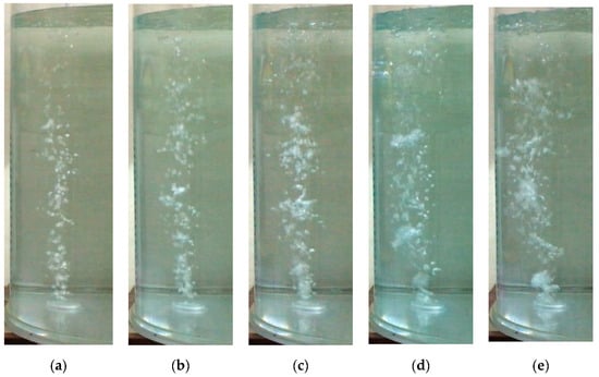
Figure 10.
The bubble motion in the water model: (a) Q = 0.0475 m3/h; (b) Q = 0.095 m3/h; (c) Q = 0.143 m3/h; (d) Q = 0.191 m3/h; (e) Q = 0.238 m3/h.
In order to apply the research results to more ladles, a dimensionless treatment was carried out for the slag layer thickness, gas flow rate and mixing time. Assuming that the diameter of the bubble is 1 cm, the product of the bubble velocity and area of the gas ports is taken as the characteristic flow rate.
where, Qb is the characteristic flow rate, m3/s; r1, r2,…, rn are the radius of gas ports, m; S is the area of gas ports of porous plugs, m2. The radius of gas port in the water model experiment is 12 mm.
The dimensionless gas flow rate was treated according to Equation (10), and the dimensionless slag layer thickness was treated according to Equation (11).
where, V* is the dimensionless gas flow rate; V is the gas flow rate, m3/h; h* is the dimensionless thickness of the slag layer; h is the thickness of the oil layer, m; hl is the depth of the molten bath, m. In the water model, the water depth is 0.643 m.
Assuming that the shape of the bubble is a spherical corona and does not deform in the process of bubble flotation, the residence time tb of the bubble in the water model can be calculated. Taking residence time tb as the characteristic time, the dimensionless mixing time can be calculated by Equation (12).
where, tb is the characteristic time, s; hl is the depth of the water, m; t* is the dimensionless time; t is the mixing time, s.
The relation between the dimensionless mixing time and dimensionless gas flow rate in the ladle with double porous plugs was shown in Figure 11, the 0, 0.0187, 0.0218, 0.0249, 0.028 and 0.0311 are dimensionless thickness in Figure 11 correspond to without oil and with oil layer of 12, 14, 16, 18, 20 mm. The trend of mixing time is consistent with Figure 4. In the water model, the optimum dimensionless flow rate is 0.157–0.183 for the ladle with double porous plugs.
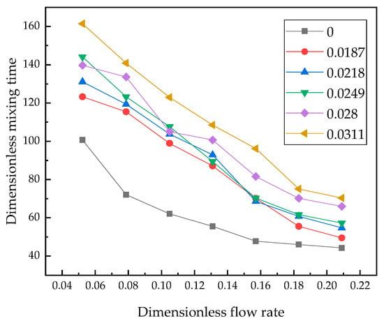
Figure 11.
The relation of dimensionless mixing time and dimensionless flow rate in the ladle with double porous plugs.
Using multiple linear regression, the relationship between dimensionless mixing time, dimensionless flow rate and dimensionless oil layer thickness was fitted by Equation (13). The coefficient of determination (R square) of fitting Equation (13) is equal to 0.942, which indicates that the equation has a high fitting degree and may be used to calculate the mixing time of the ladle with double porous plugs.
The area of the slag eye in the water model with a single porous plug at different dimensionless flow rates and dimensionless oil thicknesses was shown in Figure 12. It can be seen from the figure that when the dimensionless flow rate increases to 0.366 (corresponding to the prototype ladle flow rate of 42 m3/h), further increasing flow rate has little effect on the slag eye area, the dimensionless flow rate corresponding to the prototype ladle is 37.595. Therefore, considering the mixing time and slag entrainment, the optimized injection mode for the prototype ladle is the double porous plug with a flow rate of 36–42 m3/h.
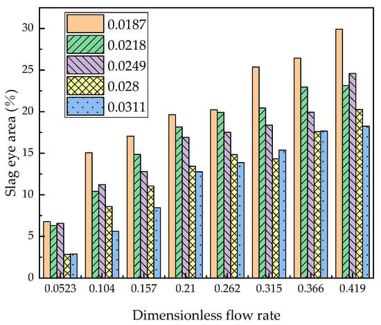
Figure 12.
The areas of slag eye at different flow rates and oil thickness in water model with single porous plug.
Using multiple linear regression, the relationship between the area of the slag eye, dimensionless flow rate and dimensionless oil layer thickness was fitted by Equation (14). The coefficient of determination (R-square) of fitting Equation (14) is equal to 0.93188, which indicates that the equation has a high fitting degree and may be used to calculate the area of the slag eye of a single porous plug ladle.
where, S% is the percentage of the slag eye area to the molten bath surface area.
Equations (13) and (14) use dimensionless experimental data, and the determinant coefficient shows that equations have a high fitting degree, so for the general ladles, Equations (13) and (14) can be used to calculate the mixing time and bare steel area by flow rate and slag layer thickness. However, in the process of dimensionless data processing, the characteristic flow rate is a fixed value, geometric similarity ratio has an effect on dimensionless flow rate, so the equations can not be directly used in the ladle. Therefore, when using Equations (13) and (14) in generic ladles, the model flow rate calculated by the geometric similarity ratio of 1:5 can be used to calculate the mixing time and slag hole area.
4. Conclusions
Through the establishment of the water model, the influence of the bottom blowing flow rate on the mixing time and slag entrapment were studied. Through dimensionless treatment and multivariate linear regression, the equations which may be used to calculate the mixing time and slag eye area of the ladle are obtained and the conclusions are as follows:
- (1)
- The bath mixing in the ladle is affected by the number of porous plugs, flow rate and slag layer. Under the same blowing flow rate, the mixing time of double porous plugs is shorter than that of a single porous plug. The mixing time of the two methods eccentric blowing is basically the same, and the mixing time decreases with the increase of the blowing flow rate, and increases with the increase of the slag layer thickness. There is an inflection point in the mixing time curve, the flow rate at the point is 0.333 m3/h (corresponding 42 m3/h in prototype), the mixing time before the inflection point changes significantly, but after the inflection point, the mixing time changes slowly. The mixing time of the ladle without the slag layer is significantly shorter than that with the slag layer.
- (2)
- The critical bottom flow rates for oil entrapment in the water model were in the range of 0.095–0.143 m3/h (18–24 m3/h for the prototype ladle) for the ladle with a single porous plug, and the critical bottom flow rate causing entrapment was 0.095 m3/h (12 m3/h for the prototype ladle) for the ladle with a double porous plug, the double porous plug is easier to the entrapped slag.
- (3)
- The entrapped slag depth increases with the argon flow rate and slag thickness; the area of slag eyes increases with the argon flow rate and decreases with slag thickness.
- (4)
- Considering the mixing time and slag entrainment, the optimized injection mode for the prototype ladle is a double porous plug with a flow rate of 36–42 m3/h.
Author Contributions
Conceptualization, Y.J., X.D.; Methodology, Y.J., F.Y.; Software, X.D., P.L.; Validation, P.L., F.Y. and X.D.; Formal analysis, Y.J., F.Y.; Investigation, P.L.; Resources, C.Z.; Data curation, L.S., J.P., and Q.C.; Writing—original draft preparation, F.Y.; Writing—review and editing, F.Y., Y.J.; Visualization, X.D.; Supervision, Y.L.; Project administration, Y.J.; Funding acquisition, C.Z., C.C.
Funding
This research was funded by the National Nature Science Foundation of China (NSFC), grant number 51674180 and grant number 51474163.
Acknowledgments
The technical assistance in the water model experiment provided by Yue Yu is greatly acknowledged.
Conflicts of Interest
The authors declare no conflict of interest.
References
- Zhu, M.Y.; Lou, W.T.; Wang, W.L. Research Progress of Numerical Simulation in Steelmaking and Continuous Casting Processes. Acta Metall. Sin. 2018, 54, 131–150. [Google Scholar]
- Parra, F.D.M.; Argáez, M.A.R.; Conejo, A.N.; Gonzalez, C. Effect of Both Radial Position and Number of Porous Plugs on Chemical and Thermal Mixing in an Industrial Ladle Involving Two Phase Flow. ISIJ Int. 2011, 51, 1110–1118. [Google Scholar] [CrossRef]
- Villeda, A.M.A.; Argáez, M.A.R.; Conejo, A.N. Effect of Slag Properties on Mixing Phenomena in Gas-stirred Ladles by Physical Modeling. ISIJ Int. 2014, 54, 1–8. [Google Scholar] [CrossRef]
- Zheng, W.; Tu, H.; Li, G.Q.; Shen, X.; Xu, Y.L.; Zhu, C.Y.; Lu, K. Physical simulation of refining process optimization for bottom argon blowing in a 250 t ladle. J. Univ. Sci. Technol. Beijing 2011, 36, 53–59. [Google Scholar]
- Liu, Z.Q.; Li, L.M.; Cao, M.X.; Li, B.K. Water model of mixing time and critical flow rate in a gas-stirred ladle. J. Mater. Metall. 2016, 15, 176–180. [Google Scholar]
- Conejo, A.N.; Kitamura, S.; Maruoka, N. Effects of Top Layer, Nozzle Arrangement, and Gas Flow Rate on Mixing Time in Agitated Ladles by Bottom Gas Injection. Metall. Mater. Trans. B 2013, 44, 914–923. [Google Scholar] [CrossRef]
- Li, L.M.; Liu, Z.Q.; Li, B.K.; Matsuura, H.; Tsukihashi, F. Water Model and CFD-PBM Coupled Model of Gas-Liquid-Slag Three-Phase Flow in Ladle Metallurgy. ISIJ Int. 2015, 55, 1337–1346. [Google Scholar] [CrossRef]
- Geng, D.Q.; Lei, H.; He, J.C. Optimization of mixing time in a ladle with dual plugs. Int. J. Miner. Metall. Mater. 2010, 18, 709–714. [Google Scholar] [CrossRef]
- Zhu, M.Y.; Inomoto, T.; Sawada, I.; Hsiao, T.C. Fluid fow and mixing phenomena in the ladle stirred by argon through multi-tuyere. ISIJ Int. 1995, 35, 472–479. [Google Scholar] [CrossRef]
- Van-Khang, N.; Bao, Y.P.; Wang, M.; Lin, L.; Li, X. Flow characteristics of argon bottom blowing in an ellipse ladle. J. Univ. Sci. Technol. Beijing 2014, 36, 1–5. [Google Scholar]
- Liu, H.P.; Qi, Z.Y.; Xu, M.G. Numerical Simulation of Fluid Flow and Interfacial Behavior in Three-phase Argon-Stirred Ladles with One Plug and Dual Plugs. Steel Res. Int. 2011, 82, 440–458. [Google Scholar] [CrossRef]
- Perez, L.E.J.; Amaro-Villeda, A.; Conejo, A.N.; Gonzalez-Rivera, C.; Ramirez-Argáez, M.A. Optimizing gas stirred ladles by physical modeling and PIV measurements. Mater. Manuf. Process. 2017, 33, 1–9. [Google Scholar]
- Amaro-Villeda, A.M.; Bello, G.J.A.; Ramirez-Argáez, M.A. Experimental Study on Mixing in Gas-Stirred Ladles with and without the Slag Phase through a Water Physical Model. MRS Online Proc. Libr. Arch. 2012, 1373. [Google Scholar] [CrossRef]
- Zhao, L.H.; Ma, W.J.; Wang, M. Physical modeling of argon bottom blowing refining in a 100 t ladle. J. Univ. Sci. Technol. Beijing 2014, 36, 140–144. [Google Scholar]
- Chattopadhyay, K.; SenGupta, A.; Ajmani, S.K.; Lenka, S.N.; Singh, V. Optimisation of dual purging location for better mixing in ladle: A water model study. Ironmak. Steelmak. 2009, 36, 537–542. [Google Scholar] [CrossRef]
- Cho, S.H.; Kim, C.W.; Han, J.W.; You, B.D.; Kim, D.S. Effect of Melt Depth and Nozzle Type on the Mixing Behavior in Bottom-Blown Steelmaking Ladle—A Water Model Approach. Mater. Sci. Forum 2006, 510–511, 494–497. [Google Scholar] [CrossRef]
- Zhan, Z.H.; Li, Q.C.; Yin, S.B.; Zhang, B.Q. Physical simulation of mixing time and critical flow rate of bottom blowing argon in a 135 t LF ladle. Contin. Cast. 2018, 43, 29–33. [Google Scholar]
- Amaro-Villeda, A.M.; Conejo, A.; Ramirez-Argáez, M.A. Effect of Slag on Mixing Time in Gas-Stirred Ladles Assisted with a Physical Model. MRS Online Proc. Libr. 2012, 1485, 101–106. [Google Scholar] [CrossRef]
- Cho, S.H.; Hong, S.H.; Han, J.W.; You, B.D. Effect of Slag Layer on Flow Patterns in a Gas Stirred Ladle. Mater. Sci. Forum 2006, 510–511, 490–493. [Google Scholar] [CrossRef]
- Patil, S.; Kumar, D.S.; Peranandhanathan, M.; Mazumdar, D. Mixing Models for Slag Covered, Argon Stirred Ladles. ISIJ Int. 2010, 50, 1117–1124. [Google Scholar] [CrossRef]
- Ramasetti, E.K.; Visuri, V.V.; Sulasalmi, P.; Mattila, R.; Fabritius, T. Modeling of the Effect of the Gas Flow Rate on the Fluid Flow and Open-Eye Formation in a Water Model of a Steelmaking Ladle. Steel Res. Int. 2019, 90. [Google Scholar] [CrossRef]
- Ramírez-Argáez, M.A.; Dutta, A.; Amaro-Villeda, A.; González-Rivera, C.; Conejo, A.N. A Novel Multiphase Methodology Simulating Three Phase Flows in a Steel Ladle. Processes 2019, 7, 175. [Google Scholar] [CrossRef]
- Gou, D.Z.; Wang, W.X.; Geng, D.Q.; Lei, H. Bubble Coalescence/Breakage and Movement in the Ladle with Argon Blowing. J. Northeast. Univ. Nat. Sci. 2018, 39, 195–199. [Google Scholar]
- Pan, S.M.; Chiang, J.D.; Hwang, W.S. Simulation of Large Bubble/Molten Steel Interaction for Gas-Injected Ladle. J. Mater. Eng. Perform. 1999, 8, 236–244. [Google Scholar] [CrossRef]
- Jardón-Pérez, L.E.; González-Morales, D.R.; Trápaga, G.; González-Rivera, C.; Ramírez-Argáez, M.A. Effect of Differentiated Injection Ratio, Gas Flow Rate, and Slag Thickness on Mixing Time and Open Eye Area in Gas-Stirred Ladle Assisted by Physical Modeling. Metals 2019, 9. [Google Scholar] [CrossRef]
- Xiao, X.G.; Xie, Y.G. Yejin Fanying Gongchengxue Congshu, 1st ed.; Metallurgical Industry Press: Beijing, China, 1997; p. 40. [Google Scholar]
© 2019 by the authors. Licensee MDPI, Basel, Switzerland. This article is an open access article distributed under the terms and conditions of the Creative Commons Attribution (CC BY) license (http://creativecommons.org/licenses/by/4.0/).