Article

Simple Alternatives to PID-Type Control for Processes with Variable Time-Delay

by
Dana Copot
1,2,*,†,
Mihaela Ghita
1,2,† and
Clara M. Ionescu
1,2,3,†
1
DySC Research Group on Dynamical Systems and Control, Department of Electrical Energy, Metals, Mechanical Constructions and Systems, Ghent University, Technologiepark 914, B9052 Ghent, Belgium
2
Core Lab EEDT, Flanders Make, 9000 Ghent, Belgium
3
Department of Automation, Technical University of Cluj Napoca, Memorandumului Street No. 28, 400027 Cluj, Romania
*
Author to whom correspondence should be addressed.
These authors contributed equally to this work.
Processes 2019, 7(3), 146; https://doi.org/10.3390/pr7030146
Submission received: 13 December 2018 / Revised: 20 February 2019 / Accepted: 25 February 2019 / Published: 8 March 2019
(This article belongs to the Section Process Control and Monitoring)

Abstract

:
Process industries include chemicals, petrochemicals, pulp and paper, steel, minerals, food, and power generation industries. Although diverse, all of these share common dynamics in terms of continuous variables and rely on the same measurements, e.g., level, flow, temperature, and pressure. They also have common actuators, such as valves and pumps. Additionally, they have variable time delays from process dynamics, such as mixing effects, measurement lines, or wireless data communication protocols. Processes with variable time delay can often lead to poor performance and instability. This paper proposes a fractional-order (FO) control design with adaptive laws for dealing with such processes, and a comparison is analysed against other controllers established in the literature for delayed dynamics. Two examples are presented to illustrate the advantages of the proposed approach. A real time-embedded control setup and interface to industrial standard devices is tested to illustrate the implementation aspects of the proposed fractional-order control. Comparison with other established controllers is given.

1. Introduction

The current state of automation in industry and process control units are largely based on developments in the 80s and has not been changed essentially since then [1]. With the advent of Industry 4.0, new challenges appear and changes to automation architecture are imminent. A large discrepancy is faced among the technology for computational power, maintenance, and ease of use. The main functionality is safety, monitoring, and control, as from ISA100.11 standard on SP100 usage classes for wireless control. The controllers nowadays show a wide availability of logical and mathematical functionality, such as auto-tuning capabilities, and adaptive Proportional-Integral-Differential (PID) laws. The integer-order PID controllers are preferred due to their simple structure, ease of implementation, and off-the-shelf tuning [2]. Studies have shown that 90% of all controllers in the process industry have a PID structure [3,4]. However, the performance of the PID controllers is limited in complex systems, such as systems with varying time delay, and more than 60% of them need re-tuning after only 6 months [5]. Time delays in processes can be responsible for poor performance, controller complexity, and the instability of systems in many processes.
As alternatives to classical integer-order PID control, Podlubny has proposed a new type of PID controllers based on fractional calculus—fractional-order PID (FOPID) controllers [6]. Studies have shown improved closed-loop performance when using FOPID controllers compared to the integer-order PID controller [7,8,9]. Additionally, the Commande Robuste d’Ordre Non Entier (CRONE) controller [10] and its improved generations [11], have indicated a high degree of robustness comparable to that of H control, at the price of theoretical control systems insight necessary for tuning controller parameters as a loop-shaping, frequency-dependent function. Freeware software for fractional-order control parameter design are already broadly available [12,13].
Variable time-delay systems have been studied for several decades and control proposed, ranging from the PID-type [14] to the MPC (Model Predictive Control)-type [15]. Established rules for easily tuning such controllers are based on approximation of high-order process dynamics by the first-order plus dead time (FOPDT) transfer function form, with additional weighting parameters for the user or operator to play. However, recently, it was shown that fractional-order controllers have the potential to enhance the performance of processes with varying time delay [16,17].
This paper tackles the control task for continuous processes with variable time delay properties. A fractional-order PID (FOPID) controller structure is proposed which permits adaptation to varying time delay values and has capabilities for auto-tuning of its parameters. Established integer-order controllers with similar features have been selected for comparison purposes, and a discussion on implementation aspects is included. Two examples are given, one in simulation and one including a real-time control loop.
This paper is structured as follows. Following some generic thoughts about automation systems and architectures, the proposed controller is described and its tuning in pragmatic context is given to the reader. Next, the realization of such non-rational transfer functions (controllers) is provided and its stability discussed. For comparison purposes, a section describing established integer-order controllers for time delay processes is included. The theoretical background is tested on two examples—a simulation case and a real-time experimental case. The results indicate the advantages of the proposed controller and robustness in a closed loop.

2. Proposed Fractional Order Controller with Adaptive Law

The benefits of fractional-order control over integer-order control have been long proven on a manifold of systems from the process industry [18]. Industrialization of controllers is much of a challenge nowadays in a competitive world, where companies tend to invest resources in order to bring down the cost of goods and improve the products’ benefits to the customers. As it was demonstrated, FOPID controllers have technical advantages over its integer-order counterparts, but the cost of producing such controllers and the cost–benefits the end user would get are still something that should be investigated. An ideal, “basic building-block” implementation of FO operators should be sought to compensate for the high-order approximation issue. This implementation must be cost-effective to facilitate industrial adoption of FO controllers [8]. A detailed review on the applicability of fractional-order control in the industry has been presented at the latest flagship conference on PID control in 2018 [8]. The aim of the paper is not to discuss their industrial application, but to make a comparison between fractional-order controllers and integer-order controllers.
In this paper, we propose a variation of fractional-order control which adapts its parameters to variations in plant’s dynamic, i.e., time constant and delay values.
In essence, high-order process dynamics can be reduced to the generic form:
G ( s ) = K T s + 1 e L s
with K the static gain of the system, L the time delay, and T the time constant, i.e., FOPDT approximation. Usually, these are extracted easily from the step response of the process in open loop. The processes are then classified into three groups, depending on the relative dynamic of the system, computed as:
τ = L L + T
whereas they are considered to be lag dominant if τ < 0.5 , balanced for τ 0.5 , and delay dominant for τ > 0.5 .
The proposed fractional-order PI controller can be represented by the following transfer function:
C F O ( s ) = K i · 1 s α + T s 1 α
and the controller is a combination of a fractional integral and fractional derivative, originating from:
C ( s ) = K i · T s + 1 s α
The open-loop transfer function of a controller and process is then given by:
C ( s ) G ( s ) = K i K e L s s α
with corresponding gain:
C ( j ω ) G ( j ω ) = K i K ω α
and phase:
ϕ = L ω α π 2
The controller can be further designed by means of Ziegler-Nichols methods [19,20] or relay feedback autotuning methods, as described in [21]. However, for the purposes of this work, model-based tuning is necessary for adapting controller parameters during operation of the process without necessity of additional tests (e.g., relay, or relay and delay).
Assume that the user defines a desired gain margin G m and a desired phase margin ϕ m . This is not unusual, since both specifications relate to time performance indexes as overshoot, settling time, rise time, and to frequency domain indexes as robustness.
We have that:
C ( j ω p ) G ( j ω p ) = G m 1 ϕ m = π + C ( j ω g ) G ( j ω g )
with ω p as the phase cross-over frequency and ω g as the gain cross-over frequency of the open-loop system and controller.
It follows that the gain is:
K K i ω g α = 1 ω p α K K i = G m
and the phase is:
ϕ m = π L ω g α π 2 π = α π 2 + L ω p
From these relations, one can extract the system:
G m = ω p ω g α ω p ω g = π α π 2 π ϕ m α π 2
In these relations, the unknown is then the fractional order α which can be extracted using numerical optimization from the relation:
G m = π α π 2 π ϕ m α π 2 α
The value of α the following controller parameters can then be determined analytically:
ω g = π ϕ m α π 2 L ω p = α α π 2 L K i = ω p α K G m = ω g α K K d = T K i
The fractional-order parameter alpha depends on the value of τ , and is almost invariant to the value of L. A summary of the tuning rules have been included in the new version of the manuscript, where a short discussion on the alpha parameter has also been included. However, since this is a standard approach, a detailed description has not been included, and instead, reference to the well-known book on fractional-order systems and control has been made. In [1], it has been shown that for different values of α , different discretization rules are obtained. As such, the choice of the alpha parameter has a weighting effect on the frequency response. More details regarding this are given in [1], and in this paper a comparison between the fractional-order controller with and without adaptation is performed. Although the above method has its advantages as it converges to an optimal solution, it requires nonlinear optimization to be executed online. Instead, we propose to make use of the approximated process parameter information to simplify the tuning procedure. Taking into account the intrinsic relation between integral action and specific dynamics of the process, one may extract the following rules of thumb [22,23,24]:
  • if τ < 0.05 , then α = 0.7
  • if 0.05 τ 0.1 , then α = τ + 0.6
  • if 0.1 τ 0.2 , then α = τ + 0.7
  • if 0.2 τ 0.4 , then α = 0.9
  • if 0.4 τ 0.6 , then α = τ + 0.5
  • if τ 0.6 , then α = 1.1
In this way, the parameter α is determined from the process characteristics, without requiring optimization. For a given phase margin, the controller parameters can be directly obtained as described above.
Notice that the values of τ may change if delay estimation techniques are introduced in the algorithm. Depending on the application, such delay estimation methods are not difficult to implement and thus can be exploited to increase robustness of the controller to variations in delay values in a larger operating range, and maintain performance despite great fluctuations in these parameters.

3. Realization of Fractional-Order Controllers

In the digital world of today’s automation systems, the realization of fractional-order controllers (FOC) relies greatly on approximating the fractional-order Laplace term ( s α ) or any other combination thereof by an interlacing of poles-zeros in a limited frequency interval. The methods for such interlacing are abundant and can be either in continuous-time, or in a discrete-time domain. However, digital control implies discrete-time polynomial forms of generic controller structure—hence, these are the most relevant.
Arriving at a discrete-time formulation of the FOC can be tedious and marked with pitfalls for the unskilled user. Tuning the order of the approximating filter (i.e., pole-zero interlacing pairs) is not an easy task, but rules of thumb are readily available in literature. A lot of methods exist, which are summarized and compared nicely in several works [25].
The literature offers several methods for approximating such non-rational continuous time-transfer functions, through various steps. The one used in this work has been outlined in [26], with various examples to illustrate the ability of the method.
De Keyser et al. [26] proposed a low-order, computationally stable, and efficient method for direct approximation of general-order (fractional-order) systems in the form of discrete-time rational transfer functions, such as processes and controllers. This is an original, efficient, direct approximation method based on the impulse response. The tedious step of computing an analytical form of the impulse response is avoided by instead using the frequency response of a fractional-order system. Employing the frequency response as a basis for computing the impulse response allows for increased flexibility of the method, and the proposed technique can be applied to any type of fractional-order system to determine its discrete-time approximation.
In short, the steps are as follows.
  • Step 1: Discretize FOC using a generating function.
    This function has been proposed as an interpolation between Euler and Tustin discretization rules:
    s ( z 1 ) = 1 + a T s 1 z 1 1 + a z 1
    with the weighting parameter a [ 0 , 1 ] and T s being the sampling period, with special cases for a = 0 (Euler discretization) and for a = 1 (Tustin discretization).
  • Step 2: Calculate the frequency response of the obtained discrete-time fractional-order system.
    This is done by substituting z = e j ω T s with 0 ω < π T s .
  • Step 3: Calculate the impulse response of the discrete-time fractional-order system.
    This step employs the inverse Fast Fourier Transform (FFT), which converts the previously computed frequency domain response into a time domain response.
  • Step 4: Identify a rational discrete time transfer function that produces a similar impulse response as that obtained from the inverse FFT.
The result is of the form:
B ( q 1 ) A ( q 1 ) = b 1 q 1 + + b n b q n b 1 + a 1 q 1 + + a n a q n a
which is then used as an input–output filter in real-time execution platforms acting on the error to bring the process output to the desired setpoint value and past control inputs.
In some applications, digital control is not used. For this, analogue realizations of FOC have already been proposed by several authors and tested in practice with great success. Some of the methods include nested multiple-loop control systems and negative impedance converters, operational amplifiers and resistor-capacitor (RC) filters, or combinations with analogue circuit electronics and micro-controller type PIC 16F876.

4. Stability of Fractional-Order Controllers

A recent novel approach for analysing stability in time-varying delayed systems has been proposed in [27], based on state space formulations of Lyapunov functions. However, in the case of FOPDT and FOC systems, these tools cannot be used due to the terms in s α . Stability of fractional order is based on the characteristic equation of the process and controller in open loop, which may be non-rational. The domain of the complex variable s is interpreted as a Riemann surface, with the principal sheet defined as π < arg ( s ) < π . In the case that α = ( 1 / n ) , with n N + , there will be n sheets in the Riemann surface, given by:
s = | s | e j ϕ , ( 2 i + 1 ) π < ϕ < ( 2 i + 3 ) π
with i = 1 , 0 , 1 , , n 2 . For instance, when i = 1 , the principal Riemann sheet is obtained, while for i = 0 the secondary Riemann sheet is obtained. To analyse the stability of fractional-order characteristic equations, mapping is used, replacing w = s α leading to the regions:
w = | w | e j θ , α ( 2 i + 1 ) π < θ < α ( 2 i + 3 ) π
For the case of commensurate-order systems, where all orders of derivation are integer multiples of a base order, the stability condition is defined by:
| θ | > α π 2
It follows that the condition for the principal Riemann sheet is obtained for i = 1 when:
α π < θ < α π
To fulfil both conditions implies:
θ α π 2 , α π α π , α π 2
which becomes for α = ( 1 / n ) , with n N + ,
θ π 2 n , π n π n , π 2 n
Hence, given the process model and the FOC, one is able to evaluate the stability before testing it in real life.

5. Integer-Order Controllers for Time Delay Systems

To better illustrate the benefits of the proposed controller, a comparison to other established controllers has been introduced. This section briefly describes the tuning rules of these comparative controllers.
A computer-aided control system design (CACSD) tool based on frequency response shaping for the Matlab software platform (2014, MathWorks, Natick, MA, USA) has been used, i.e., the FRTool [28]. The interface requires the availability of a process model and allows specifications as overshoot, settling time, robustness, phase margin, and gain margin. The toolbox permits introducing poles and zeros such that the frequency response beeline represented as a Nichols plot of the process and controller loop shapes around the specifications. The tool has been extensively used and can be freely obtainable upon request from the authors. The integer-order proportional-integer controller has the structure:
C 1 ( s ) = K p + K p T i 1 s
and is not adaptive, since its parameters do not explicitly depend on the L values of delay.
Most of the controllers are designed taking into account the process description from (1). Two controllers are selected, with the following tuning rules for balanced systems and delay dominant systems:
C 2 ( s ) = K p + K p T i 1 s ,   with K p = 1 K 0.2978 τ + 0.000307 T i = T 0.8578 τ 2 3.402 τ + 2.405
and
C 3 ( s ) = K p + K p T i 1 s ,   with K p = ( 0.7303 + 0.5307 T / L ) ( T + 0.5 L ) T i K ( T + L ) T i = T + 0.5 L
Another well-established set of controllers for processes with time delay were designed in [14]. Two controllers are used, namely:
C 4 ( s ) = K p + K p T i 1 s k c = T ( L + T 0 ) × K , K p = k c T + 0.5 × L T ; T i = T + 0.5 × L ;
with T 0 being a weighting parameter for the user, and:
C 5 ( s ) = K p + K p T i 1 s K p = 0.35 L + 2 × T K × L ; T i = T + L / 2 ;
Finally, important robustness issues have been addressed in a tuning methodology based on internal model control principles in [29,30]. Specifications such as maximum sensitivity are allowed for optimal tuning. The controller structure has been selected as:
C 6 ( s ) = K p T i s + 1 T i s K p = 1 K T T 0 + L T i = m i n ( T , 4 × ( T 0 + L ) ) ;
In all these controllers, except for the one from (22), they are adaptive in the term L, given the values of L are available during process operation via delay estimation techniques. The choice for the controllers selected for comparison in this paper is that these are the well-established controllers for this type of process (i.e., time delay systems).

6. Case Studies of Variable Time Delay Processes

6.1. Case Study 1: Quality Control in Continuous Steel Casting

In the continuous casting process, molten steel flows from a ladle, through a tundish into the mold. Once in the mold, the molten steel freezes against the water-cooled copper mold walls to form a solid shell. Drive rolls lower in the machine continuously withdraw the shell from the mold at a rate or “casting speed” that matches the flow of incoming metal, so the process ideally runs in a steady state. The block diagram of the process is given in Figure 1.
Based on baseline dominant dynamic characteristics, a simplified structure of the control loop has been elaborated hereafter. The values are not coming from real-life data, but they are able to capture the main dynamical properties necessary to illustrate the feasibility of the controlled loop in a realistic environment.
The transfer function for the hydraulic actuator which moves the stopper in the tundish is given by:
H A ( s ) = 39.48 s 2 + 8.796 s + 39.48
A PD-type controller transfer function has the following form:
P D = 0.3 ( s + 5 ) 2
The dynamics of the stopper are given by:
S t o p p e r ( s ) = 0.8 s + 1
The actual stopper position is measured with a position sensor which has the following dynamics (the output of the sensor is expressed in V):
S e n s o r ( s ) = 1 0.1 s + 1
The next element represents the effect of a variation of the stopper position on the flow speed of the steel [31]. The electro-magnetic stirrer is used to change the speed of the flow of steel in order to maintain the speed within a certain interval. As long as the speed of the steel flow is within these limits, the quality of the steel slab will be sufficient. The transfer function representing these dynamics is given by:
E M S ( s ) = 1 s 2 + 2 s + 1
Temperature gradient loss is represented by first-order dynamics, followed by a time delay indicating the measurement of temperature at the end of the continuous casting line. The transfer function capturing the delay and loss effects is given by:
D L ( s ) = 0.8 10 s + 1 e 30 s
In practice, all these time constants and delay values may vary slightly due to variations in the level of steel in the tundish and stopper position variations, and effects of disturbances (e.g., new ladle supply, noise, vibrations).
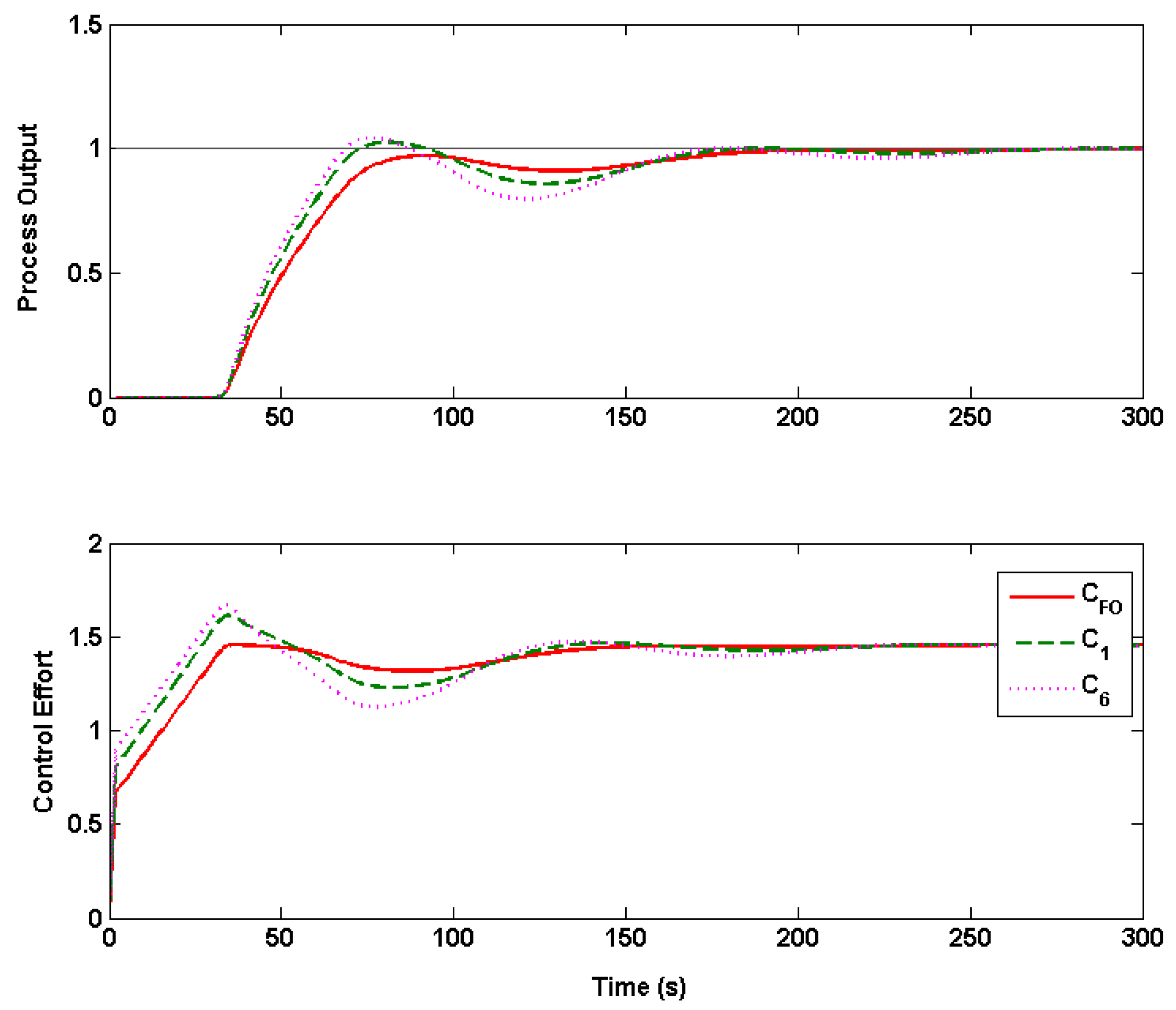
The proposed fractional-order controller was applied on a simulator of the real system in MATLAB/Simulink based on Figure 1. The results obtained from the simulation are depicted in Figure 2. It can be noticed that the proposed fractional-order controller ( C F O ) with adaptation has very good closed-loop performance (i.e., no overshoot).
The advantages of FOPID controllers can be seen most clearly by invoking frequency-domain analysis and control design methods. Seminal works on the subject include [23,24]. A clear theoretical demonstration of the advantages of fractional-order control was provided by [32] by considering Bode’s ideal transfer function. The gain margin property provides the advantage of the system being insensitive to gain changes. The variations of the gain result in the change in crossover frequency, but the phase margin of the system is unchanged. The performance of the controllers is evaluated using the Relative mean square error (MSE) performance index. The MSE for the simulated controllers is: C F O 0.0841; C 1 0.0878 and C 6 0.0884.
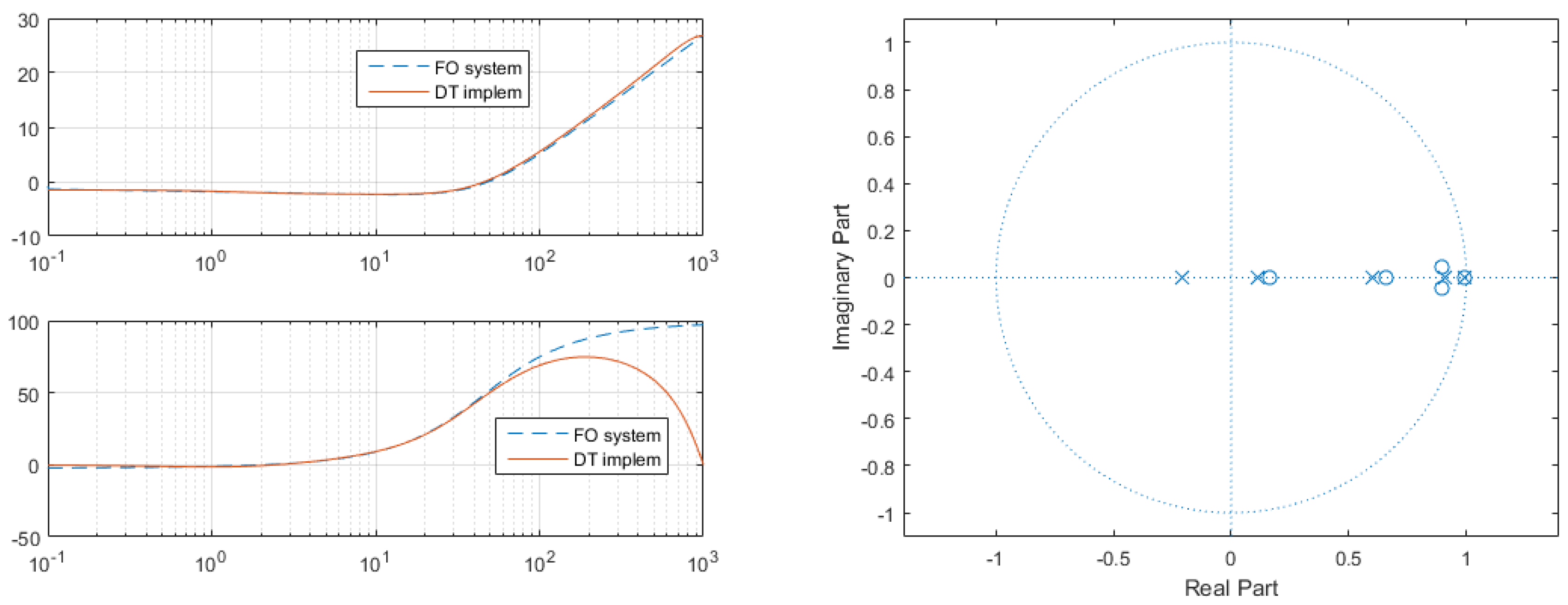
To show the stability of the proposed fractional-order controller, the bode characteristic and the pole-zero-map have been given in Figure 3. Based on Ziegler-Nichols rules for controller tuning, a K p parameter has been introduced. The controller parameters are: K p = 0.6429, K i = 0.0112, and K d = 0.1683, and the fractional-order parameter α = 1.1.

6.2. Case Study 2: Temperature Control

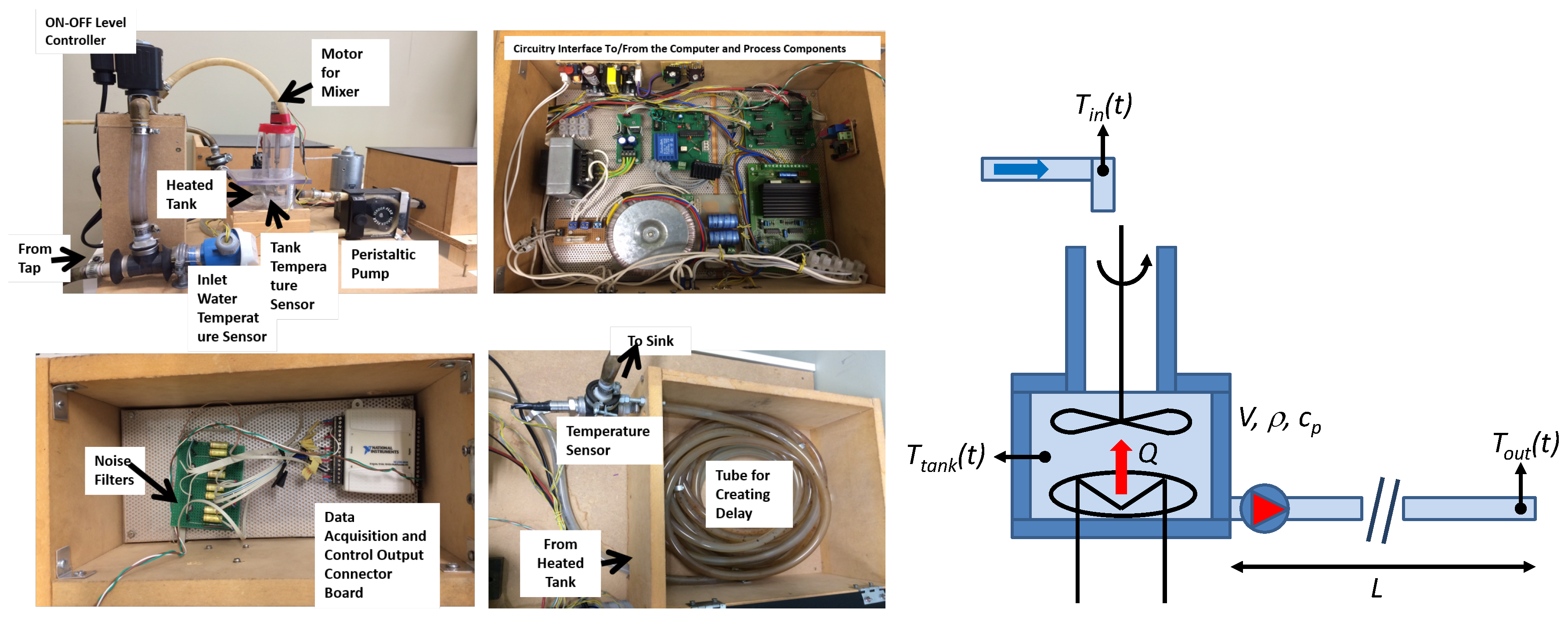
The process by which the new proposed controller will be implemented and tested in real-time has been described in [15] and controlled by nonlinear model predictive control to account for nonlinearities and variable time delays. The system is shown in Figure 4 together with its schematic representation. It consists of a heated tank in which the water level is controlled by a controllable valve, resulting in a constant water volume V. A submerged electrical heater delivers a constant heat flow Q which is used to warm up the water. By manipulating the flow q ( t ) , which is the outflow of the heated tank, the temperature in the vessel can be controlled. As the volume in the tank is constant, the same amount of water enters the tank from the cold tap. The outflow q ( t ) is created using a peristaltic pump (D2028, SparkFun Electronics, Boulder, Colorado) driven by a 24 DC motor. The relationship between the input voltage of the motor and the flow created by the pump is linear. At the outlet of the tank, a flexible tube of length L is attached, which introduces a variable transport delay T d ( t ) into the system. Two PT100 sensors (B&B sensors, Donaueschingen, Germany) are used to measure both the inlet temperature T i n ( t ) and the outlet temperature T o u t ( t ) at the end of the tube. A third temperature sensor (B&B sensors, Donaueschingen, Germany) is used to measure the tank temperature T t a n k ( t ) . A mixer ensures a homogeneous temperature in the water tank.
For estimation purposes, the mathematical model of the system is derived. The nonlinear dynamics of the tank between the outflow q ( t ) of the tank and the tank temperature T t a n k ( t ) are expressed by the following energy balance equation:
ρ c p V d T t a n k ( t ) d t = Q + ρ c p q ( t ) [ T i n ( t ) T t a n k ( t ) ]
where ρ and c p are the density and the specific heat of water, respectively; V is the volume of the water in the tank; Q is the amount of supplied heat; and T i n ( t ) is the measured inlet temperature. Heat losses are neglected when considering this balance equation. T t a n k ( t ) is related to the outlet temperature by the following relationship:
T o u t ( t ) = T t u b e ( t T d ( t ) )
In a discrete time domain, the variable time delay T d ( t ) , which is the time a water particle needs to travel from the tank to the outlet of the tube, can be represented by N d (number of sampling periods) as:
T s i = 1 N d q ( t i ) = L S
with T s as the sampling period, L the length of the tube, and S the cross-sectional area of the tube. Note here that if the flow is constant, this expression can be simplified to:
N d ( t ) = L S T s q ( t ) = V t u b e T s q ( t )
The numerical values of the heater tank are listed in Table 1.
A FOPDT approximation has been made for the step response evaluated around the operating point defined by ( q * = 0.025 /s, T t a n k * = 31.11 C):
T t a n k ( s ) q ( s ) = 764.5 14 s + 1 e T d s
In Figure 5, the simulation results of the proposed fractional-order controller and the integer-order controller are presented. The performance of the controllers was evaluated using the relative mean square error (MSE) performance index. The MSE for the simulated controllers is: C F O 38.7189; C 1 39.0995 and C 6 39.0492.
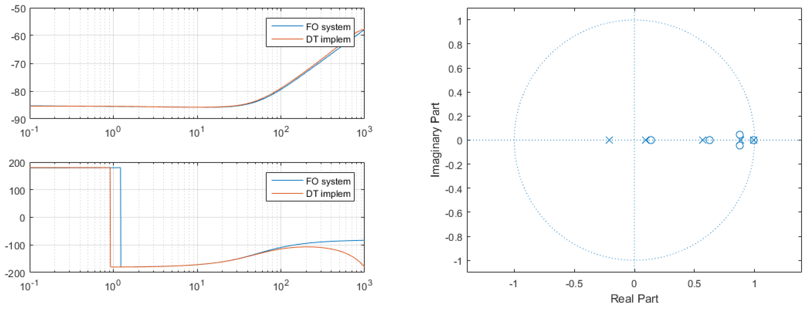
To prove stability of the proposed fractional-order controller, the bode characteristic and the pole-zero-map are given in Figure 6. Based on Ziegler-Nichols rules for controller tuning, a K p parameter has been introduced. The controller parameters are: K p = −4.7 × 10 5 ; K i = −6.49 × 10 7 and K d = −5.19 × 10 6 , the fractional-order parameter α = 1.1.

6.2.1. Real-Time Implementation

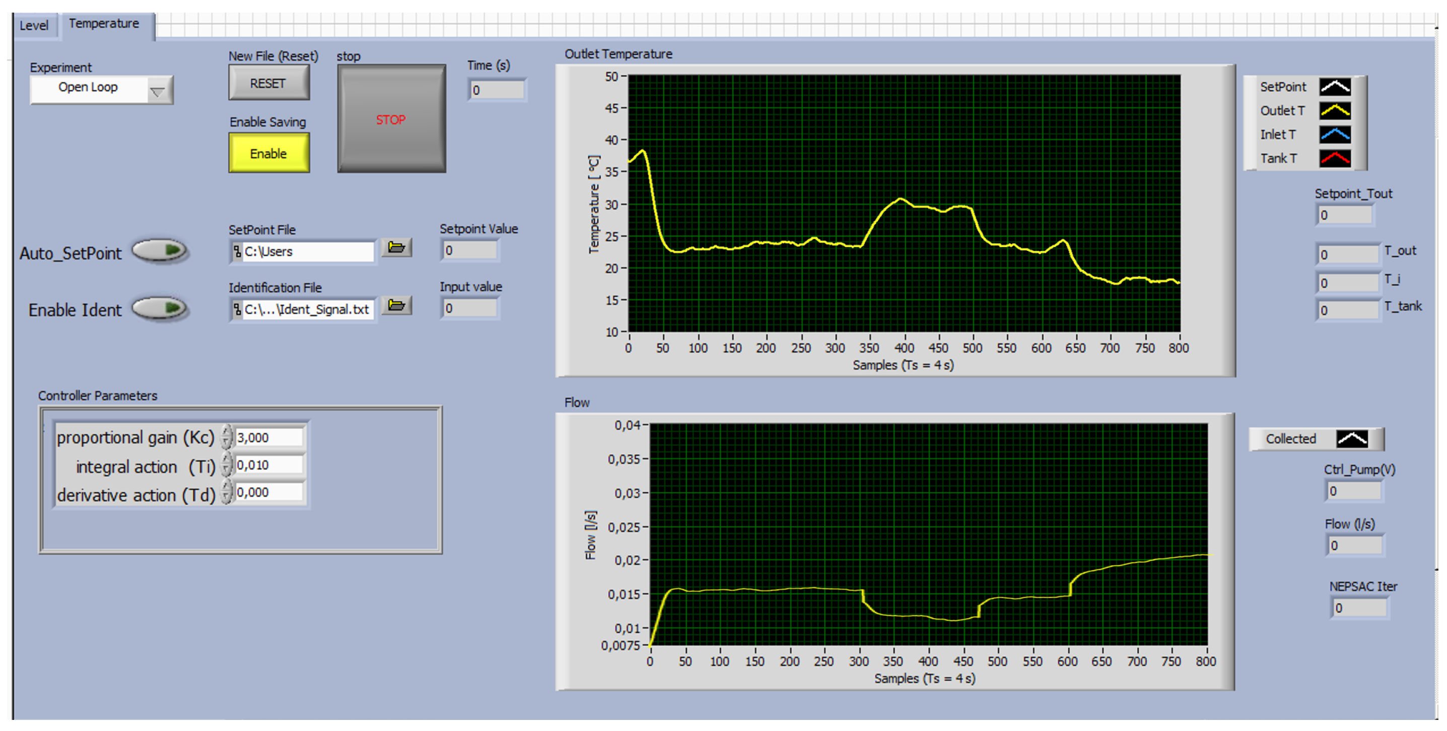
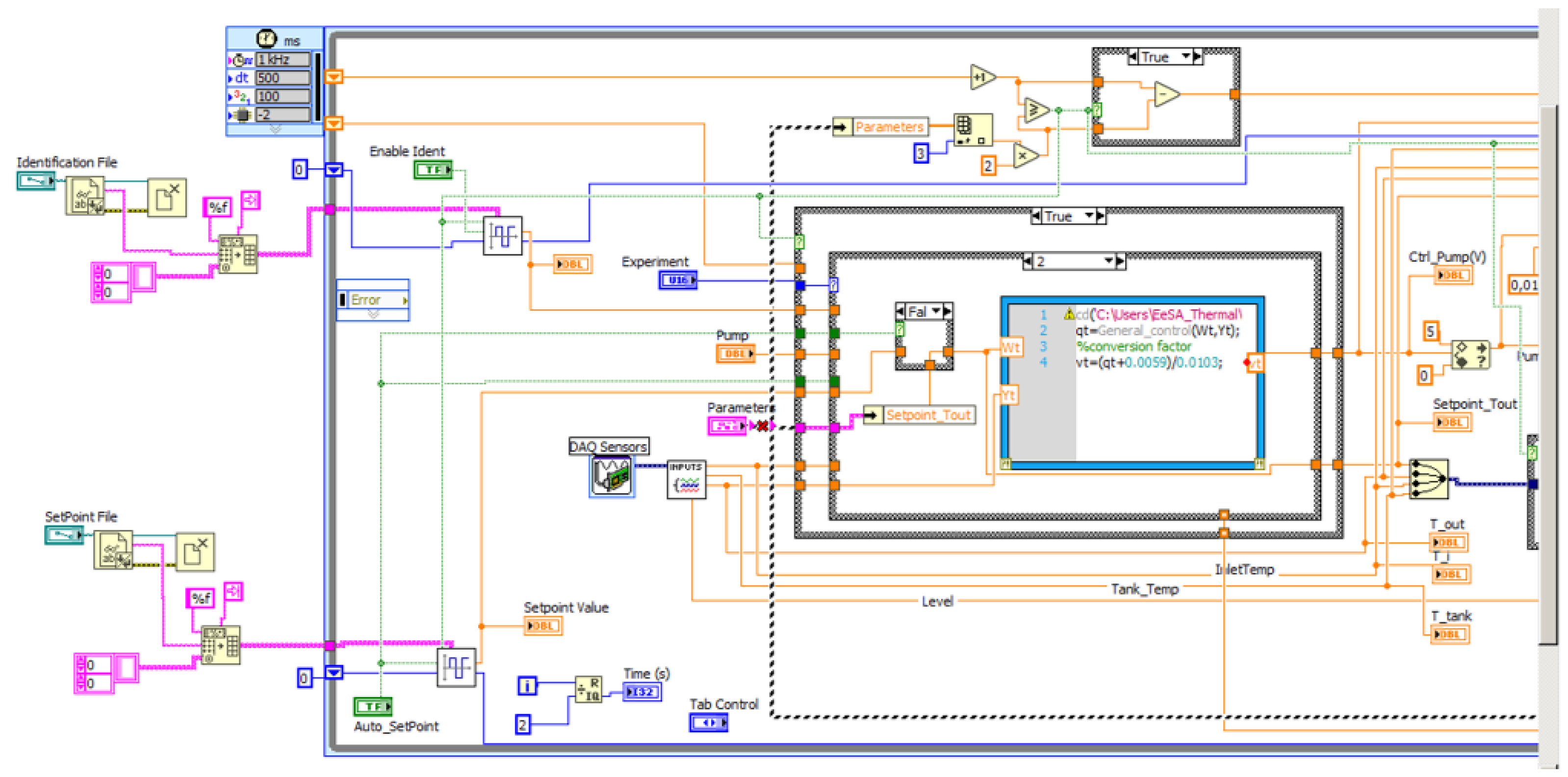
To implement of the designed controllers on the real plant, the Laboratory Virtual Instrumentation Engineering Workbench (LabVIEW) platform (National Instruments, 11500 N Mopac Expwy Austin, TX 78759-3504) was used. LabVIEW consists of Labview software (National Instruments, 11500 N Mopac Expwy Austin, TX 78759-3504, 2016), a data acquisition card (DAQ), and peripheral feedback equipment. LabVIEW uses data-flow programming, and the programs are known as Virtual Instruments (VIs). The VI has three components: block diagram, front panel, and icons/connectors. The front panel for the real-time experiment is shown in Figure 7 and the block diagram is shown in Figure 8. The front panel is the user interface which includes the control signal indications, the controller parameters, and wave chart of the set point, outlet temperature, inlet temperature, tank temperature, and flow.
All controllers have been designed and tested in MATLAB/Simulink. To deploy the controllers to the real plant, communication between Matlab and LabVIEW is required. Therefore, to be able to implement the proposed control strategy, the following steps need to be performed:
  • Design and test the controller in MATLAB/Simulink;
  • Create an Embedded function with the designed controller;
  • Create and configure the dynamic-link library (dll);
  • Define the path in the LabVIEW interface;
  • Select and configure the parameters of the inputs and outputs function in call library functions;
  • Define the path to save data, save the VI project, and test the controller.

6.2.2. Real-Time Results

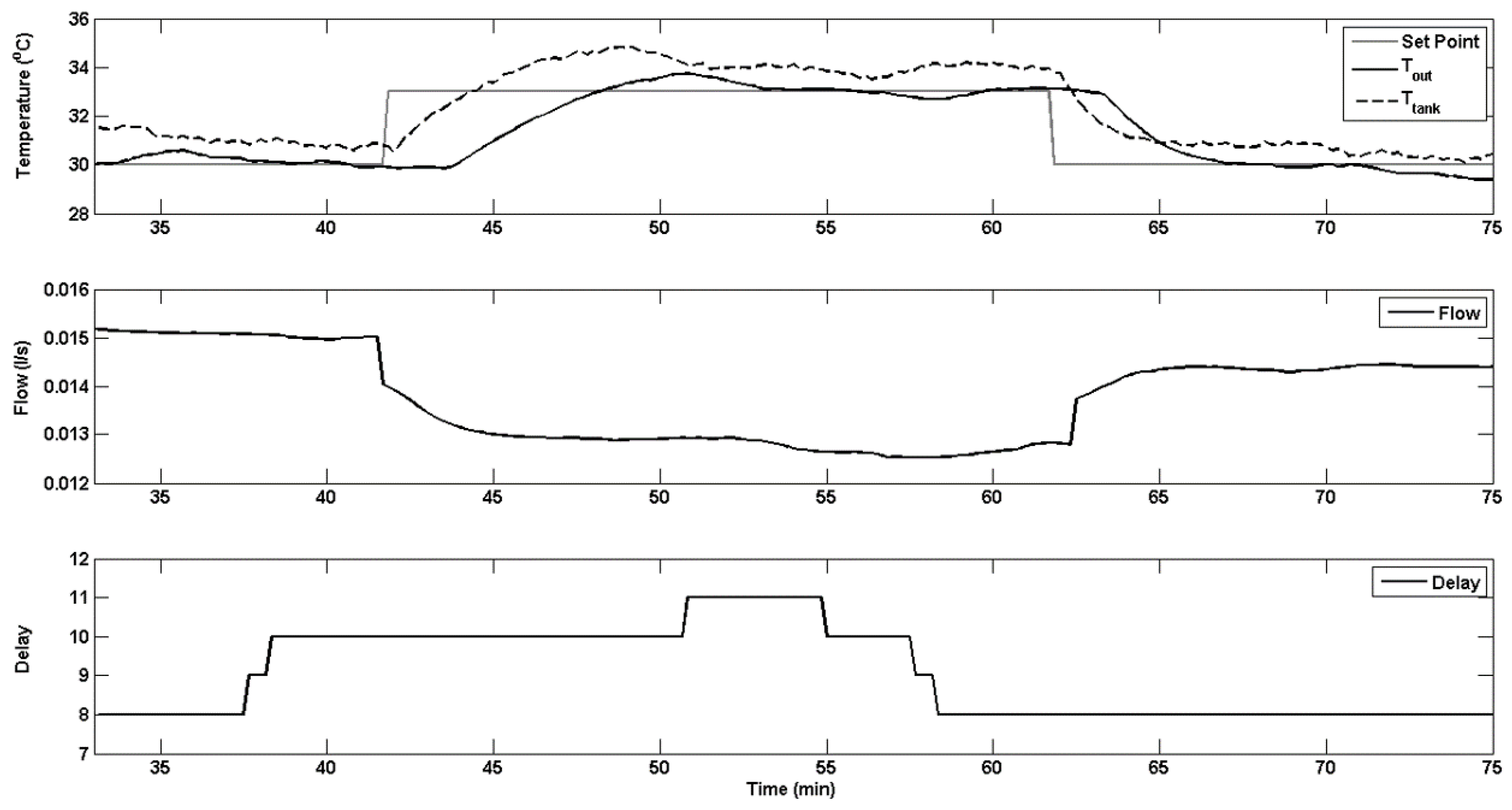
The proposed fractional-order controller C F O from (3) was implemented on the real system. The experiment on the real system consists of a series of step changes to the temperature from 30.4 C–31.5 C–32.7 C–35.9 C to 30.4 C. The results of this experiment are shown in Figure 9. Note from Figure 9 that the proposed FOC is able to track the reference temperature accurately and with a lower settling time. The delay profile is depicted in Figure 9 on the lower graph.
In Figure 10, the inlet temperature profile is shown. It can be noticed that the temperature has a fast decrease in the beginning of the experiment. This is expected behavior since the temperature of the water entering the tank depends on the geothermal variation and particularities of the buildings. After some time, the inlet temperature tends to stabilize; however, there are some fluctuations. These fluctuations can be due to disturbances, as for this example, a tap at another sink has been opened.

7. Conclusions

In this paper, alternatives to PID-type control for processes with variable time delay have been proposed. The mathematical description of the fractional-order controller and its implementation in the analogue and the discrete domains has been presented. A fractional-order controller with adaptive laws has been tested, both in simulation and experimentally. The obtained results indicate that fractional-order controllers have the potential to outperform classical controllers. The aim of this paper was to make a comparison analysis with other fractional-order controllers with and without adaptation laws. A comparison with other well-established controllers for processes with time delay was also performed, and the advantages of the fractional-order controller with adaptive law have been highlighted.

Author Contributions

Conceptualization: C.M.I. and D.C.; Methodology: C.M.I. and D.C.; investigation and data curation: M.G.; writing original draft preparation: D.C. and M.G.; writing, review and editing: C.M.I., D.C., M.G.; supervision: C.M.I.

Funding

This research received no external funding.

Conflicts of Interest

The authors declare no conflict of interest.

References

  1. Starr, K.; Petersen, H.; Bauer, M. Control loop performance monitoring—ABB’s experience over two decades. IFAC-PapersOnLine 2016, 49, 526–532. [Google Scholar] [CrossRef]
  2. Aström, K.J.; Hägglund, T. Advanced PID Control; Instrument Society of America: Research Triangle Park, NC, USA, 2006. [Google Scholar]
  3. Yamamoto, S.; Hasimoto, I. Present status and future needs: The view from Japanese industry. In Proceedings of the 4th International Conference on Chemical Process Control, Padre Island, TX, USA, 17–22 February 1991. [Google Scholar]
  4. Samad, T. A survey on industry impact and challenges thereof. IEEE Control Syst. 2017, 37, 17–18. [Google Scholar]
  5. Bauer M, I. Craig, Economic assessment of advanced process control—A survey and framework. J. Process Control 2008, 18, 2–18. [Google Scholar] [CrossRef]
  6. Podlubny, I. Fractional-order systems and PIλDμ-controllers. IEEE Trans. Autom. Control 1999, 44, 208–214. [Google Scholar] [CrossRef]
  7. Petras, I.; Dorcak, L.; Kostial, I. Control quality enhancement by fractional order controllers. Acta Montan. Slovaca 1998, 3, 143–148. [Google Scholar]
  8. Tepljakov, A.; Alagoz, B.; Yeroglu, C.; Gonzalez, E.; Hosseinnia, H.; Petlenkov, E. FOPID controllers and their industrial applications: A survey of recent results. In Proceedings of the 3rd IFAC Conference on Advances in Proportional-Integral-Derivative Control, Ghent, Belgium, 9–11 May 2018; pp. 25–30. [Google Scholar]
  9. Yuan, J.; Chen, Y.; Fei, S. Analysis of actuator rate limit effects on first-order plus time-delay systems under fractional order proportional integral control. In Proceedings of the 3rd IFAC Conference on Advances in Proportional-Integral-Derivative Control, Ghent, Belgium, 9–11 May 2018; pp. 37–42. [Google Scholar]
  10. Oustaloup, A. La Dérivation non Entière: Théorie, Synthèse et Applications; Hermes: Paris, France, 1995. [Google Scholar]
  11. Bauer, M.; Craig, I. CRONE control system design toolbox for the control engineering community: Tutorial and case study. Philos. Trans. R. Soc. A 2008, 18, 2–18. [Google Scholar]
  12. van Duist, L.; van der Gigten, G.; Toten, D.; Saikumar, N.; Hosseinnia, H. FLOreS—Fractional Order Loop Shaping MATLAB Toolbox. In Proceedings of the 3rd IFAC Conference on Advances in Proportional-Integral-Derivative Control, Ghent, Belgium, 9–11 May 2018; pp. 545–550. [Google Scholar]
  13. Cech, M. Web based fractional PID controller design: www.pidlab.com. In Proceedings of the 3rd IFAC Conference on Advances in Proportional-Integral-Derivative Control, Ghent, Belgium, 9–11 May 2018; pp. 563–568. [Google Scholar]
  14. Normey-Rico, J. Control of Dead-Time Processes; Springer: London, UK, 2007. [Google Scholar]
  15. Sbarciog, M.; De Keyser, R.; Cristea, S.; de Prada, C. Nonlinear predictive control of processes with variable time delay. A temperature control case study. In Proceedings of the 17th IEEE International Conference on Control Applications, Part of IEEE MCSC, San Antonio, TX, USA, 3–5 September 2008; pp. 1001–1006. [Google Scholar]
  16. Pop, C.; Ionescu, C.; De Keyser, R.; Dulf, E. Robustness evaluation of fractional order control for varying time delay processes. Signal Image Video Process. 2012, 6, 453–461. [Google Scholar] [CrossRef]
  17. Pop, C.; Ionescu, C.; Keyser, R.D. Time delay compensation for the secondary processes in a multivariable carbon isotope separation unit. Chem. Eng. Sci. 2012, 80, 205–218. [Google Scholar] [CrossRef]
  18. Petras, I.; Vinagre, B. Practical application of digital fractional order controller to temperature control. Acta Montan. Slovaka 2002, 7, 131–137. [Google Scholar]
  19. Åström, K.; Hägglund, T. Revisiting the Ziegler-Nichols step response method for PID control. J. Process Control 2004, 14, 635–650. [Google Scholar] [CrossRef]
  20. Nise, N. Control Systems Engineering; John Wiley and Sons Inc.: Hoboken, NJ, USA, 2017. [Google Scholar]
  21. Ionescu, C.; De Keyser, R. The next generation of relay-based PID autotuners (PART1): Some insights on the performance of simple relay-based PID autotuners. In Proceedings of the IFAC Conference on Advances in PID Control (PID’12), Brescia, Italy, 28–30 March 2012. [Google Scholar]
  22. Vilanova, R.; Visioli, A. PID Control in the Third Millenium; Springer: Berlin/Heidelberg, Germany, 2012. [Google Scholar]
  23. Monje, C.; Vinagre, B.; Feliu, V.; Chen, Y. Tuning and auto-tuning of fractional order controllers for industry applications. Control Eng. Pract. 2008, 16, 798–812. [Google Scholar] [CrossRef] [Green Version]
  24. Monje, C.; Chen, Y.; Vinagre, B.; Xue, D.; Feliu, V. Fractional-order Systems and Controls: Fundamentals and Applications. In Advances in Industrial Control; Springer: London, UK, 2010. [Google Scholar]
  25. De Keyser, R.; Muresan, C.; Ionescu, C. A novel auto-tuning method for fractional order PI/PD controllers. ISA Trans. 2016, 62, 268–275. [Google Scholar] [CrossRef] [PubMed]
  26. De Keyser, R.; Muresan, C.I.; Ionescu, C.M. An efficient algorithm for low-order direct discrete-time implementation of fractional order transfer functions. ISA Trans. 2018, 74, 229–238. [Google Scholar] [CrossRef] [PubMed] [Green Version]
  27. Lee, T.; Park, J.H. A novel Lyapunov functional for stability of time-varying delay systems via matrix-refined-function. Automatica 2017, 80, 239–242. [Google Scholar] [CrossRef]
  28. De Keyser, R.; Ionescu, C. FRtool: A frequency response tool for CACSD in Matlab. In Proceedings of the IEEE Conference on Computer Aided Control Systems Design, Munich, Germany, 4–6 October 2006; pp. 461–466. [Google Scholar]
  29. Skogestad, S. Simple analytic rules for model reduction and PID controller tuning. J. Process Control 2003, 13, 291–309. [Google Scholar] [CrossRef] [Green Version]
  30. Grimholt, C.; Skogestad, S. Should we forget the Smith Predictor? In Proceedings of the 3rd IFAC Conference on Advances in Proportional-Integral-Derivative Control, Ghent, Belgium, 9–11 May 2018; pp. 769–774. [Google Scholar]
  31. Dekemele, K.; Ionescu, C.; Doncker, M.D.; Keyser, R.D. Closed loop control of an electromagnetic stirrer in the continuous casting process. In Proceedings of the European Control Conference, Aalborgh, Denmark, 29 June–1 July 2016; pp. 61–66. [Google Scholar]
  32. Vinagre, B.; Chen, Y.; Petráš, I. Two direct Tustin discretization methods for fractional-order differentiator/integrator. J. Frankl. Inst. 2003, 340, 349–362. [Google Scholar] [CrossRef]
Figure 1. Schematic representation of the continuous casting process.
Processes 07 00146 g001
Figure 2. Comparison between the proposed fractional-order controller and other established controllers (the controllers with satisfactory performance). In the upper figure the process output for the proposed control strategies is shown while in the lower figure the control effort is presented. For the upper figure the same legend as for the lower figure applies.
Processes 07 00146 g002
Figure 3. Left: Bode characteristics of the proposed fractional-order controllers (FOC). Upper graph: Magnitude as a function of frequency (rad/s); Lower graph: Phase as a function of frequency (rad/s). Right: Pole zero map of the proposed FOC.
Processes 07 00146 g003
Figure 4. The heater tank system and its schematic representation.
Processes 07 00146 g004
Figure 5. Comparison between the newly proposed fractional order proportional-integer-derivative controller and integer-order controllers for temperature control.
Processes 07 00146 g005
Figure 6. Left: Bode characteristics of the proposed FOC. Upper graph: Magnitude as a function of frequency (rad/s); Lower graph: Phase as a function of frequency (rad/s). Right: Pole zero map of the proposed FOC.
Processes 07 00146 g006
Figure 7. LabVIEW interface of the temperature control system.
Processes 07 00146 g007
Figure 8. Block diagram VI in LabVIEW for control implementation.
Processes 07 00146 g008
Figure 9. Upper graph: Performance of the proposed fractional-order controller. Middle graph: Control effort. Lower graph: Delay profile.
Processes 07 00146 g009
Figure 10. Inlet temperature profile during the experimental test of the proposed FOC.
Processes 07 00146 g010
Table 1. Parameters of the heater tank.
NotationParameterValueUnit
ρ water density1kg/
τ t u b e time constant of the tube transfer function11.1-
c p specific heat coefficient of water4186J/(kg C)
K t u b e gain of the tube transfer function0.95-
Qamount of heat2000W
T i n ( t ) inlet temperature12 C
T s sampling period4s
Vvolume of the tank0.35
V t u b e volume of the tube1.7