Article

Salp Swarm Optimization Algorithm-Based Controller for Dynamic Response and Power Quality Enhancement of an Islanded Microgrid

1
School of Electrical Engineering, Universiti Teknologi Malaysia, Johor Bahru 81310, Malaysia
2
Department of Electrical Engineering, Mehran University of Engineering and Technology SZAB Campus Khairpur Mirs, Khairpur 66020, Pakistan
3
Department of Electronic Engineering, The Islamia University of Bahawalpur, Bahawalpur 63100, Pakistan
4
Department of Electrical Engineering, Balochistan University of Information Technology, Engineering and Management Sciences, Quetta 87300, Pakistan
*
Author to whom correspondence should be addressed.
Processes 2019, 7(11), 840; https://doi.org/10.3390/pr7110840
Submission received: 8 October 2019 / Revised: 5 November 2019 / Accepted: 7 November 2019 / Published: 10 November 2019

Abstract

:
The islanded mode of the microgrid (MG) operation faces more power quality challenges as compared to grid-tied mode. Unlike the grid-tied MG operation, where the voltage magnitude and frequency of the power system are regulated by the utility grid, islanded mode does not share any connection with the utility grid. Hence, a proper control architecture of islanded MG is essential to control the voltage and frequency, including the power quality and optimal transient response during different operating conditions. Therefore, this study proposes an intelligent and robust controller for islanded MG, which can accomplish the above-mentioned tasks with the optimal transient response and power quality. The proposed controller utilizes the droop control in addition to the back to back proportional plus integral (PI) regulator-based voltage and current controllers in order to accomplish the mentioned control objectives efficiently. Furthermore, the intelligence of the one of the most modern soft computational optimization algorithms called salp swarm optimization algorithm (SSA) is utilized to select the best combination of the PI gains (kp and ki) and dc side capacitance (C), which in turn ensures optimal transient response during the distributed generator (DG) insertion and load change conditions. Finally, to evaluate the effectiveness of the proposed control approach, its outcomes are compared with that of the previous approaches used in recent literature on basis of transient response measures, quality of solution and power quality. The results prove the superiority of the proposed control scheme over that of the particle swarm optimization (PSO) and grasshopper optimization algorithm (GOA) based MG controllers for the same operating conditions and system configuration.

1. Introduction

Due to the recent developments in power electronics and artificial intelligence technology, the flexible deployment and performance of distributed generators (DGs) have been improved significantly. This is necessary in order to cope up with the increasing power demand along with improvement in power quality and reliability of the power system. Furthermore, these DGs combine together with a group of loads to form a small entity of an electrical network called Microgrid (MG) [1]. MG can be interconnected with the utility grid through a static switch at point of common coupling (PCC) or operated isolated. In the grid-tied mode, the power can be imported or exported between the MG and main grid as needed while in the islanded mode the MG operates to support the load at its own without any external support from the utility grid. Furthermore, in grid-tied mode, the voltage magnitude and frequency are dictated by the giant power system, while power flow between DGs and the main grid is the major control concern. Contrary to that, one of the very basic tasks of any control architecture in islanded mode is to regulate the voltage magnitude and frequency at their rated values. A general structure of the MG is shown in Figure 1.
Figure 1 portrays a very general structure of an MG where the DGs (wind and solar in this case), battery banks and loads are connected to the point of common coupling through three-phase circuit breakers. To inject a controlled amount of power at rated voltage and frequency, generally, a controlled non-linear power electronic device is utilized. These devices are non-linear in nature and hence need to be properly controlled in order to achieve a higher power quality along with the proper accomplishment of control objectives such as voltage, frequency and power flow regulation. In grid-connected mode, the sole objective of the MG controller is to ensure proper sharing of power among DGs and between MG and utility grid while in islanded mode the prime control objective is to regulate voltage and frequency at their rated values along with controlled power-sharing among DGs and power quality. Since MG faces more challenges in the islanded mode as compared to that of the grid-connected mode, this research is purely dedicated to the islanded mode of MG operation.
The study aims to improve the transient response of an islanded MG under different operating conditions. The mentioned task is accomplished by using the intelligence of the salp swarm optimization algorithm (SSA) to obtain the optimal combination of Proportional plus Integral (PI) controller parameters and dc-link side capacitance value provides the least settling time and overshoot during DG injection and load switching conditions. SSA is one of the most intelligent optimization algorithms introduced by Mirjalili et al. [3]. As compared to Genetic Algorithm (GA) and Particle Swarm Optimization (PSO), SSA is a more evolved algorithm for solving the different optimization problems [3]. It has been applied and found better than its competitor algorithms in solving many engineering problems like parameter identification of Photo-Voltaic (PV) modules [4], optimal allocation and capacity of DGs [5], extracting optimal parameters of fuel cells [6], training ANN for pattern recognition [7] and load-frequency control [8]. The mentioned studies have duly verified the effectiveness of SSA in solving the studied optimization problems better than conventional optimization techniques. This research work utilizes the intelligence of SSA for obtaining the optimal combination of PI gains and dc-link capacitance value to improve the dynamic response of studied islanded MG and regulating voltage and frequency under the DG insertion and load change conditions. The controller utilizes the droop control in the control structure as a power-sharing controller along with the voltage and current control loops. To authenticate the effectiveness of the proposed control technique, its performance is compared with that of the PSO and GOA based controllers for the identical operating conditions.
The subsequent sections are described as follows; Section 2 discusses the modern MG control architectures and a brief literature review of the available techniques used to tackle the presented problem. Section 3 describes the considered islanded MG along with its complete mathematical model and control architecture. In Section 4 the proposed methodology for obtaining an optimal transient response of studied MG system and basics of SSA along with the justification for considered fitness function has been provided. Finally, in Section 5, the obtained results are presented.

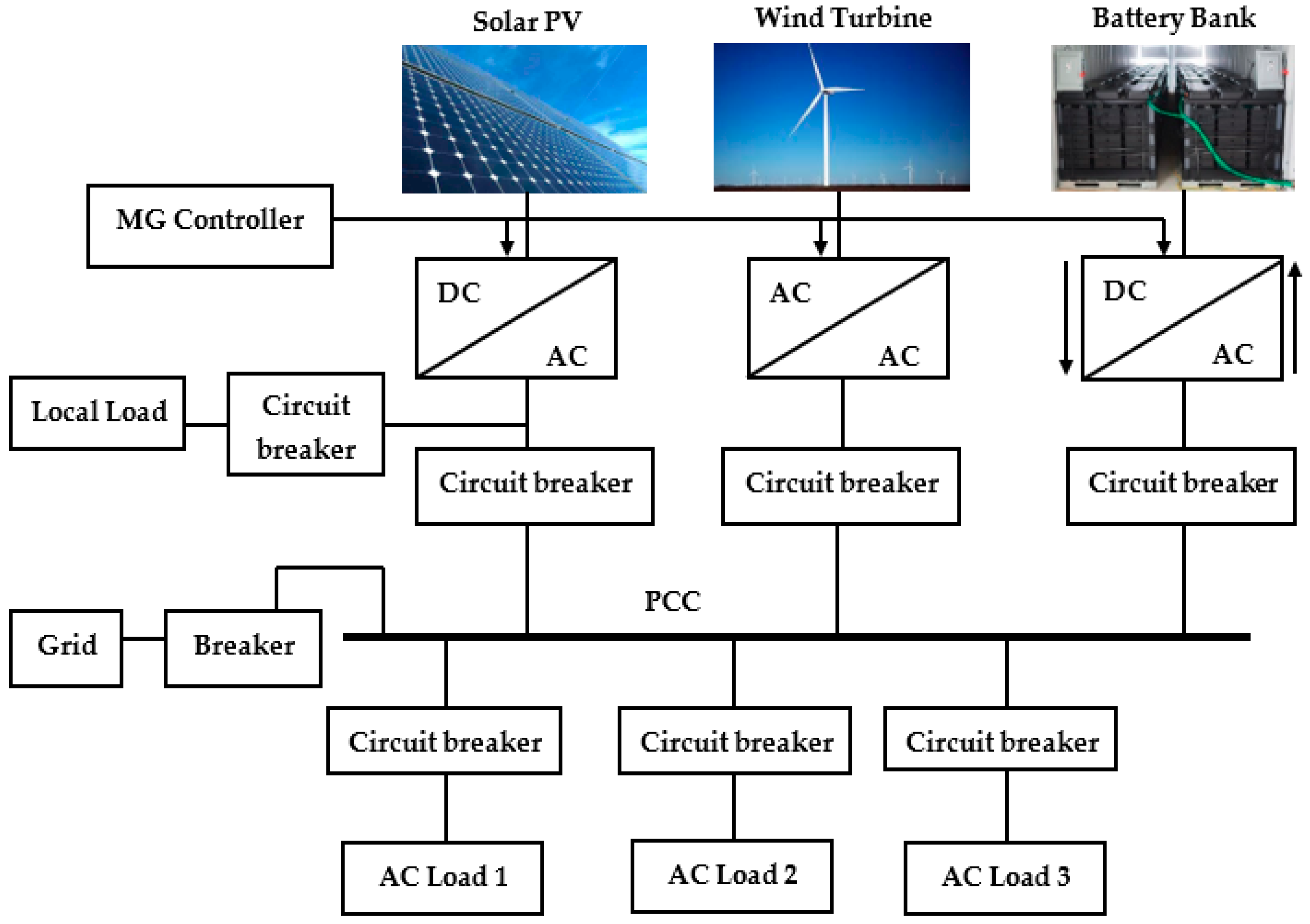
2. Modern Microgrid Control Architectures

Recently, several control architectures have been developed for the islanded MGs using proportional plus integral (PI) regulator-based power, voltage and current control loops. The generalized control architecture of the MG based on the above-mentioned control loops is shown in Figure 2.
For the grid-tied mode, there is no requirement of the voltage controller as it is dictated by the main grid while the power controller may be replaced by a voltage controller in case of the autonomous mode. Due to the robust structure and simple control action, PI controllers are found to be the most widely used regulators in these control loops. The main drawback of using PI regulators in modern MG control architectures is that their performance is dictated by their proportional and integral gains (kp and ki). Hence, selection of these gains decides the overall performance of the controller and consequently, the studied system. Over the last years, these gains were selected by using the “trial and error” or Ziegler-Nicolas (Z-N) method. These conventional methods of PI tuning suffer from many disadvantages, such as excessive time consumption, uncertainty in gain selection and complex calculations which restricted PI controller application in the latest MG control architectures up to a large extent. Most recently, with the development in the area of artificial intelligence (AI) and its applications in optimization field, several AI methods such as fuzzy logic (FL), genetic algorithm (GA) and particle swarm optimization (PSO) were explored to optimize PI controller parameters for dynamic response enhancement of islanded ac MGs. The results presented in the mentioned research papers clearly show the importance of the AI techniques in obtaining optimal PI parameters, which led to the enhanced transient response of the studied MG systems.
Many researchers around the world have worked on solving the mentioned optimization problem using different AI techniques. Al-Saedi et al. [9] developed an MG controller for controlling voltage and frequency of an autonomous MG. The PSO was utilized to optimize the system parameters and hence dynamic response. The developed controller successfully regulated the voltage magnitude and managed to keep it within standard limits (±5% of the rated value). However, the frequency level was not up to the standard (±1% of the rated value) during transient conditions. An attempt was made to solve the mentioned problem in reference [10] where the PSO based controller was developed for regulating voltage and frequency of an islanded MG. The designed controller successfully regulated the frequency and kept in well within the standard limits despite the huge load and source variations. However, the study did not consider the voltage profile, which is one of the very important parameters in the islanded mode of MG. Authors in the references [11,12] developed an AI-based controller for the voltage regulation of an islanded MG using Pareto based BB-BC and hybrid big-bang big-crunch (BB-BC) algorithms, respectively. In both case studies, the frequency declined to 59.7 Hz from its rated value (60 Hz) during DG insertion and load change conditions. Most recently, Qazi et al. [13] used the whale optimization algorithm (WOA) for regulating frequency and voltage independently by formulating two different fitness functions in an islanded MG. However, it may be noted that the voltage and frequency are two interrelated parameters [12], and therefore, it is not practically possible to independently optimize these two inter-dependent parameters. Most recently, in November 2018, the authors in reference [14] explored the grasshopper optimization algorithm (GOA) in order to regulate voltage and frequency along with the optimal transient response of an islanded MG. The authors achieved a better dynamic response as compared to previous quoted literature; however, as compared to WOA and PSO, no significant improvement was observed in overshoot and settling time during load change conditions. To address the stated limitation, for the very first time as per the best of authors’ knowledge, an additional parameter that is dc side capacitance has been adopted as optimization variable along with four gains of two PI regulators in islanded MG controls. In almost all previous MG control architectures the dc side capacitance value has been adopted based on “trial and error” method whose disadvantages are already discussed earlier.

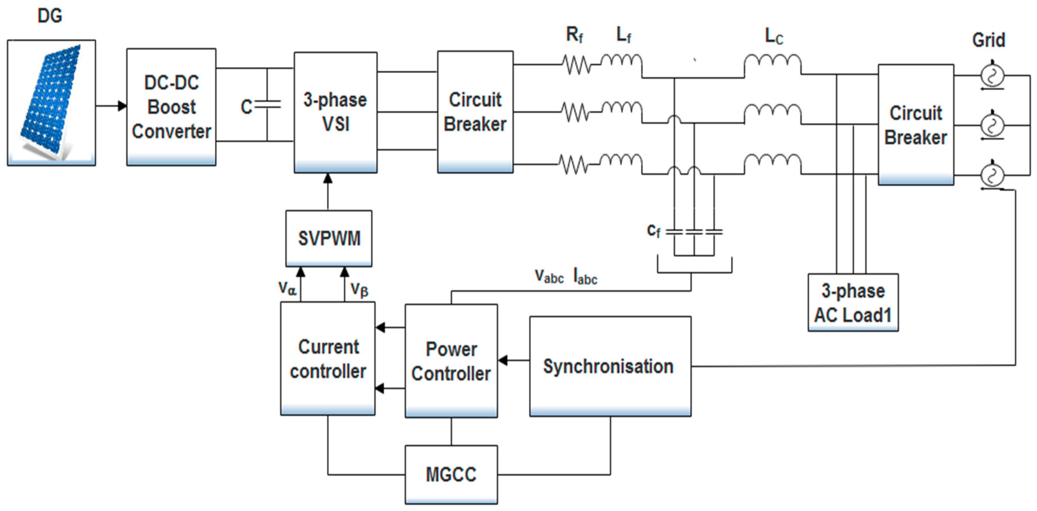
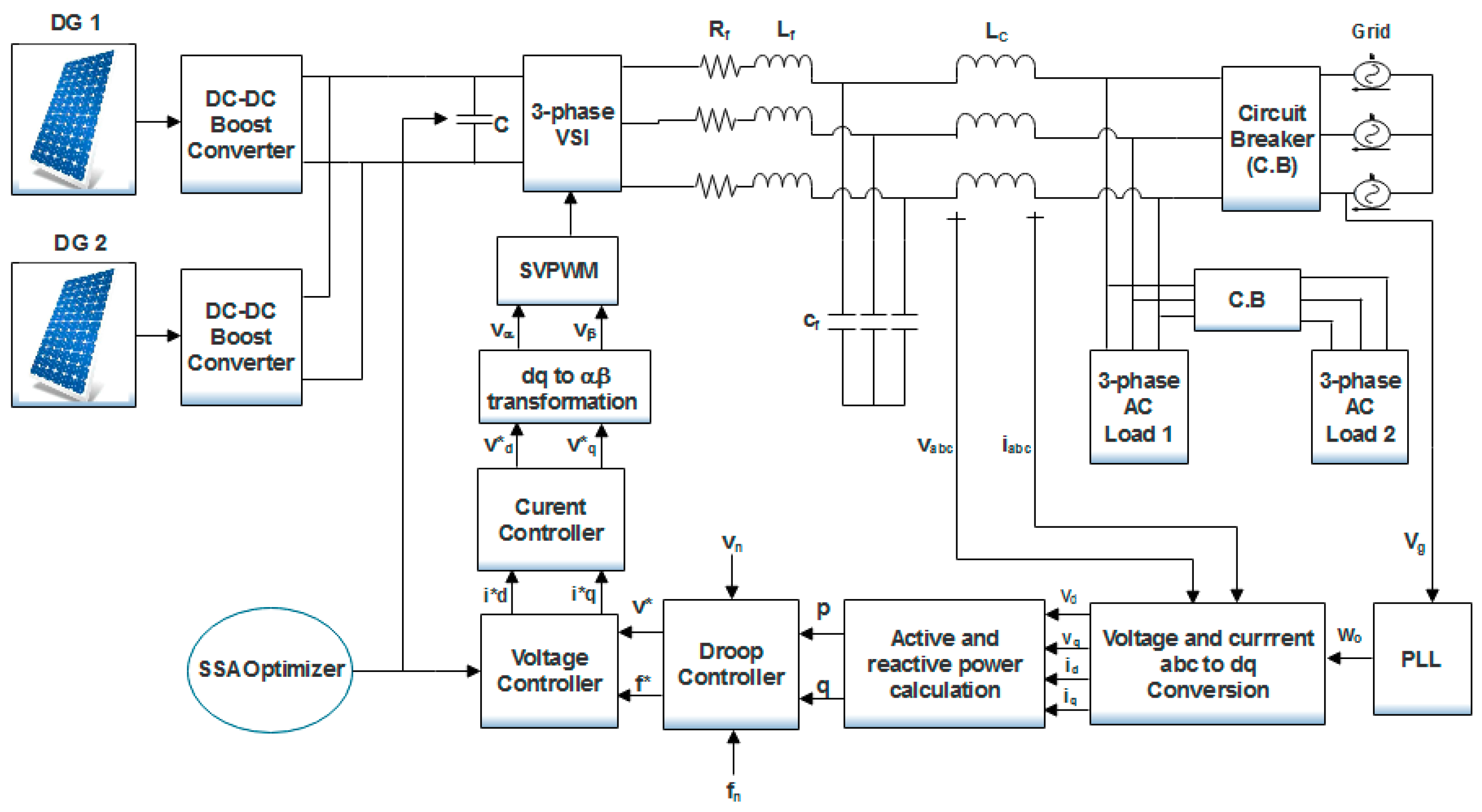
3. Proposed Islanded MG Architecture

In this section, a detailed insight of the islanded MG model along with the proposed SSA based voltage-frequency (v-f) controller is provided. A comprehensive block diagram of the power and control circuit of the studied islanded infinite bus MG system is shown in Figure 3.
The power circuit contains two solar photovoltaic (PV) modules, a three-phase voltage source inverter (VSI), RLC filter, coupling inductor and two RL loads. Since the studied MG is operated in an islanded mode, the utility grid disconnected from the rest of the network using a three-phase circuit breaker. In order to control the voltage and frequency of the studied MG system, the voltage and current signals are converted from abc to dq reference frame by using well-known Park’s transformation as given in Equations (1) and (2), respectively:
[ v d v q v o ] =   2 3   [ cos θ cos ( θ 2 π 3 ) cos ( θ + 2 π 3 ) sin θ sin ( θ 2 π 3 ) sin ( θ + 2 π 3 ) 1 2 1 2 1 2 ] [ v a v b v c ]
[ i d i q i o ] =   2 3   [ cos θ cos ( θ 2 π 3 ) cos ( θ + 2 π 3 ) sin θ sin ( θ 2 π 3 ) sin ( θ + 2 π 3 ) 1 2 1 2 1 2 ] [ i a i b i c ]
The basic aim of this transformation is to achieve an equivalent two-phase orthogonal stationary reference frame from three-phase rotating signals. This conversion is necessary because the PI controllers do not work properly on sinusoidal reference signals. A more detailed version of the proposed control architecture is depicted in Figure 4.
After obtaining the voltage and current signals in dq reference frame, the active and reactive power is measured using Equations (3) and (4), respectively:
p =   v d i d +   v d i q
q =   v d i q   v q i q
In order to remove the harmonic contents from the fundamental active and reactive power curves, a low pass filter (LPC) with the following transfer function models is used:
P p =   w c s +   w c
Q q =   w c s +   w c
It may be noted that in conventional synchronous generator-based power systems, the voltage and frequency of the system are regulated by an auto-voltage regulator (AVR) and governor system respectively. However, these methods do not work for DGs such as solar PV, where the output power from panels is dc and fluctuating in nature due to unpredictable weather conditions and continuous load switching. Hence, in this case, a droop controller is utilized to compensate for the voltage and frequency sags and swells during any source and load change conditions. Droop control can instantly compensate for the voltage and frequency drop without any communication link with the central MG controller. It does so by continuously measuring the power output and accordingly changing the reference signals (v* and f*) for the voltage controller. The dynamics for the droop control are given in Equations (7) and (8):
f * =   f n   k w P
v * =   v n   k v Q
The values for the v n and f n are taken as 220 V and 50 Hz, respectively. The two output signals of the droop controller, i.e., which v* and f*, are then compared with their respective nominal values using a comparator and errors (ev and ef) are fed to two PI controllers whose gains are optimized by SSA optimizer. The sole aim of optimizing PI gains is to achieve an optimal dynamic response of the studied MG system with minimum overshoot and settling time in voltage and frequency curves. In order to precisely track the current reference signals ( i d * and i q * ), two more PI controllers are used in the current controller block of the proposed controller. Since the gains for the PI controller used in voltage controller block were optimized using SSA, optimizing gains for PI regulators in the current controller block will increase the complexity and duration of the overall optimization process and may result in un-optimal results at the end due to the excessive number of optimization variables. The transfer function equations for the current controller as derived from Figure 4 are as in Equations (9) and (10):
v d * = k p v +   k i v s   ( i d r e f   i o d )   w L f i o q + v d
v q * = k p f +   k i f s   ( i d r e f   i o d ) + w L f i o d + v q
Finally, the space vector pulse width modulation (SVPWM) technique is used to generate the firing pulses for VSI so that a regulated quantity of power with high power quality can be injected to feed the connected load.

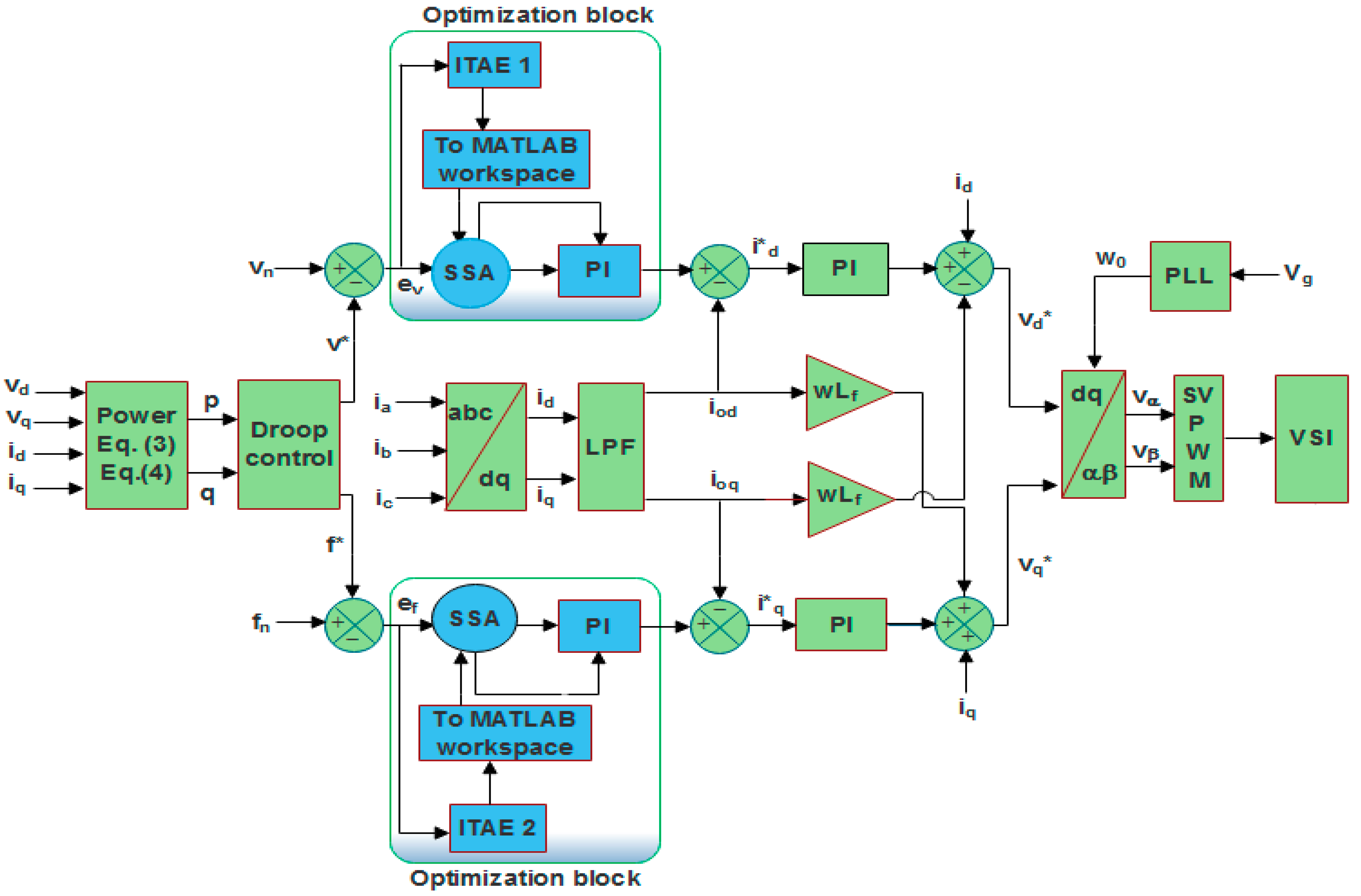
4. Proposed Methodology

This section is further divided into two subsections. The first section discusses the mathematical formulation of SSA for optimizing MG control parameters, while the fitness function to be minimized by the SSA is presented in the second section.

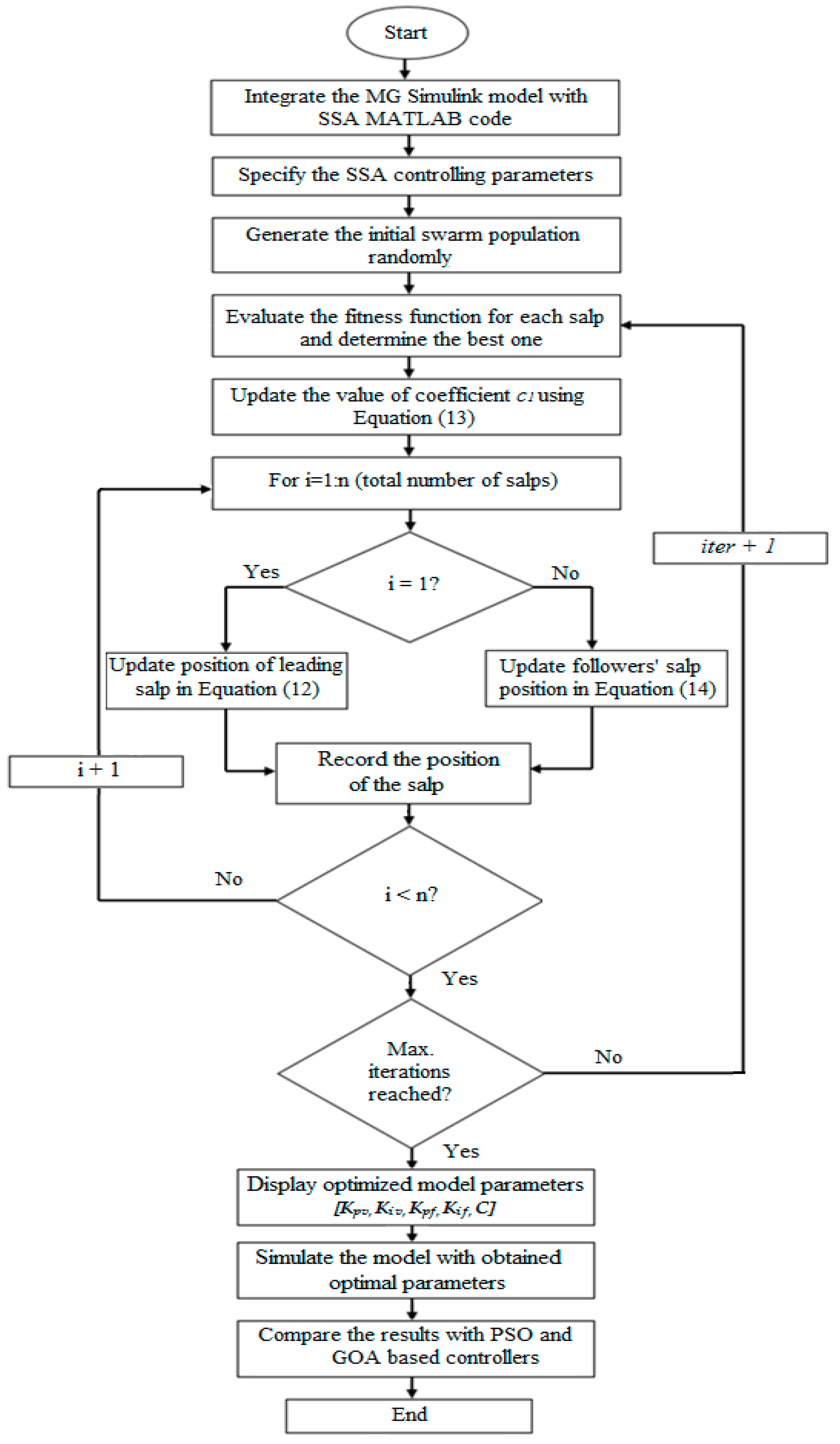
4.1. Salp Swarm Algorithm and Its Implementation

In this section, the motivation behind the proposed optimization algorithm along with its complete mathematical model is discussed in detail. Salps are the family member of the Salpidae group. They possess the translucent barrel-shaped figure and move similar to that of jellyfish. To model their movement mathematically, their initial positions are initialized randomly as portrayed in Equation (11) [3]:
K 1 1 : n = r a n d   ( ) ( u b j   l b j ) + l b j , j   n o .   o f   v a r i a b l e s
where K 1 1 : n shows the initial positions of the salps, u b j and l b j represents the upper and lower limit, respectively, and rand (…) is the command for generating random numbers between 0–1.
Afterward, two groups are formed: leader and followers. All the salps except those at the rear are labeled as followers while the front ones are called leaders. The leader salps guide the whole swarm while the followers follow them continuously in order to search for a food source labeled as M in this case. Similar to other metaheuristic optimization techniques, the location of each salp is defined in a defined search space having n number of dimensions that are equal to the number of controlled parameters in an optimization problem. Furthermore, the location of the entire number of salps is kept in a matrix K, which is defined in Equation (12) [3]:
K j 1 =   { M i + c 1 ( ( u b j   l b j ) c 2 +   l b j ) c 3 0 M i c 1 ( ( u b j   l b j ) c 2 +   l b j ) c 3 < 0
where the symbol K j 1 symbolizes the position of leader salp in the jth dimension, M i shows the location of the food source in the jth dimension and c1, c2 and c3 denote the random numbers. It is significant to note that, unlike conventional optimization methods such as GA and PSO, the SSA effectively manages to avoid trapping into local minimum due to its adaptive optimization mechanism. SSA updates the position of follower salps with respect to each other and allows them to move gradually towards the leading salp, which prevents the algorithm from stagnating into the local optima. Thus, the algorithm produces an optimal or near-optimal solution precisely during an optimization process [3]. Furthermore, SSA has better exploration versus exploitation balancing capability, which is the fundamental requirement for reaching the best available solution for an optimization problem. As can be seen from Equation (12), the leader salp upgrades its location with reference to the food source only. The coefficient c1 in Equation (12) is one of the very important parameters in SSA since it helps in balancing the exploitation and exploration characteristics of SSA and is defined in Equation (13):
c 1 = 2 e ( 4 l L ) 2
where l represents the current number of iteration, while L denotes the number of maximum iterations. The symbols c2 and c3 used in Equation (12) represents the random numbers between 0 and 1. In order to upgrade the location of the follower salps, a similar equation to that of Newton’s law of motion is used:
K j i = 1 2   a t 2 + v 0   t
where i ≥ 2 and K j i is the positions of ith follower salp in jth dimension, t denotes the time and v0 is the symbol used for the velocity at the start of the optimization process, which is generally taken as 0. As the time in the optimization procedure can be replaced by the iterations and the variance between two successive iterations cannot be in a fractional number, hence by assuming v0 = 0, the Equation (14) can be re-written as given underneath:
K j i =   K j i +   K j i 1 2
where i ≥ 2 and K j i denotes the position of ith follower salp in jth dimension. It is important to note that the salp chain possesses the potential of moving towards the continuously changing global optimum (food source) in order to find a better solution by exploring and exploiting the defined search space. Some of the very important features of SSA which make it different from the conventional optimization algorithms are listed as follows [3];
  • The algorithm keeps the best-obtained solution after each iteration and assigns it to the global optimum (food source) variable. Hence, it can never be wiped out even if the whole population deteriorates.
  • SSA updates the position of the leading salp with respect to the food source only, which is the best solution obtained thus far; therefore, the leader salp always explores and exploits the space around it for a better solution.
  • SSA updates the position of follower salps with respect to each other in order to let them move towards the leading salp gradually.
  • Gradual movements of follower salps prevent the SSA from being easily stagnating into local optima.
  • Parameter c1 is decreased adaptively over the course of iterations, which helps the algorithm to explore the search space at starting and exploits it at the ending phase.
  • SSA has only one main controlling parameter (c1), which reduces the complexity and makes it easy to implement.
The above-mentioned merits of SSA make it potentially able to solve the optimization problems better than conventional optimization methods and hence became the motivation for the current research work. In addition, the adaptive mechanism of SSA allows this algorithm to find an accurate estimation of the best solution by continuously avoiding the trapping into local solutions.
Further details of SSA along with its pseudo-code and benchmarking against the conventional optimization methods can be found in reference [3]. It may be noted that for tuning the characteristics of the SSA for solving a specific problem, two parameters may be adjusted, namely the number of searching salps and the total iterations’ number. The complete methodology of obtaining optimal PI parameters and dc-link capacitance for enhancing the dynamic response of the grid-tied MG system using SSA is depicted in the flow-chart shown in Figure 5.
Similar to other metaheuristic optimization methods, SSA spread a specified number of random search agents within searching space in the first stage. Based on the operating mechanism of SSA as given in Figure 5, these search agents are permitted to change their position in the restricted search space to minimize the stated Fitness Function (FF) subjected to a defined set of constraints. It is important to note that the mathematical model for simulating salp chains cannot be directly employed to solve optimization problems. In other words, there is a need to tweak the model according to the studied system configuration in order to make it applicable to solve the specific optimization problem. The ultimate goal of any optimization algorithm is to determine the global optimum which is generally carried out by minimization or maximization process of a defined FF. In SSA, the mentioned objective is accomplished by making the leading salp to move towards the food source and the follower salps follow the leading salp as per the governing equations of the algorithm. In the context of the optimization process, the food source is treated as the global optimum; therefore, the salp chain automatically moves towards it. It is assumed that the best solution obtained so-far is the global optimum and the food source to be chased by the salp chain until the termination criterion is reached. In the current case study, the completion of the maximum number of iterations is set as the termination criteria of the optimization process. Hence, once the pre-decided maximum number of iterations is reached, the obtained optimized PI gains and capacitance value are collected from the MATLAB workspace and are exported to the PI controller and dc side capacitor block in MG Simulink model. After that, the MG Simulink model is executed for 0.5 s to obtain the optimized power, voltage and current curves.

4.2. Fitness Function Formulation

The operating point of the power system fluctuates continuously and abruptly due to continuous and sudden load variations. Furthermore, in grid-connected MG power systems, the sudden insertion and desertion of DGs into the power system may push it into an unstable region of operation due to large power fluctuations and overshoots. One of the solutions to avoid such a situation is to use optimized controller parameters that can provide an optimum transient response of the system. Keeping in view the mentioned issues in the power system, the two gains of each PI controller (Kpv, Kiv, Kpf, Kif) placed in the first control loop of the studied MG controller along with the dc link capacitance (C) are optimized by SSA. In fact, for all metaheuristic and evolutionary optimization methods, the presence of the FF is a compulsory requirement that evaluates the fitness of each and every search agent and selects the best one for further comparison during the next iteration. In the context of the current study, where the optimal tuning of PI controller is required, four FF criterions that are generally considered in the literature are Integral Square Error (ISE), Integral Absolute Error (IAE), Integral Time Square Error (ITSE) and Integral Time Absolute Error (ITAE). However, ITAE is the most widely used FF criterion than its compilators due to the easy implementation, realistic error indexing and better outcomes [15,16]. The ITSE and ISE used to square the error which produces large perturbation in results even for a very small change in error signal, and hence generates impractical results. In addition, due to the continuous-time multiplication with the absolute value of error, the ITAE produces more realistic error indexing as compared to IAE. Hence looking at the prominent features of the ITAE criterion, it is adopted as the FF to be minimized in this study. Mathematically, the ITAE is expressed as provided in Equations (16) and (17):
I T A E 1 =   0 t | e v |   d t
I T A E 2 =   0 t | e f |   d t
where t refers to the total time of simulation, | e v | and | e f | are the absolute values errors in active and reactive power measurement, respectively, which are figured out by arithmetically deducting the measured power values from the setpoint power values. The overall FF is formed by mathematically adding two measured ITAE values as given in Equation (18):
F F =   M i n {   0 t   | e v | d t +   0 t   | e f | d t   }
It is important to understand that the magnitude of the FF in Equation (18) needs to be minimized by SSA in order to acquire the optimal PI parameter values that provide an optimum transient response of the MG system. The islanded MG modeling along with its controller and formulation of FF is carried out in MATLAB/SIMULINK version 2018a, while the coding of SSA along with its parameters like the total number of salps, iterations and optimization variables are depicted in the MATLAB editor window. Furthermore, the Simulink model is made to run for the pre-set maximum number of iterations using the “sim ( )” command from the editor window. Finally, once the simulation is finished, the optimized PI gains are placed into the corresponding PI block in MATLAB/SIMULINK model to achieve the optimal dynamic behavior of the designed MG power system.

5. Results and Discussion

The evaluation of the dynamic response for the developed islanded MG system is studied by using MATLAB/SIMULINK version 2018a. In order to make a justified evaluation of PSO, GOA and SSA the identical system parameters are used for both simulations and are depicted in Table 1.
The optimized parameters obtained at the end of the optimization process are provided in Table 2.
The considered MG is purely operated in islanded mode, and hence, no grid-connection is made throughout its operation. Furthermore, the voltage magnitude and frequency curves are measured at the load connection point. In addition, since the operating conditions, the number of iterations and simulation time is pre-defined for studied islanded MG model, the optimized variables obtained through PSO, GOA and SSA at the end of the simulation ensure optimal dynamic response of the studied MG system for its complete operation. The obtained optimized parameters are inserted into the islanded MG SIMULINK model and the developed model is then evaluated for the three cases which are thoroughly discussed in the subsequent subsection.

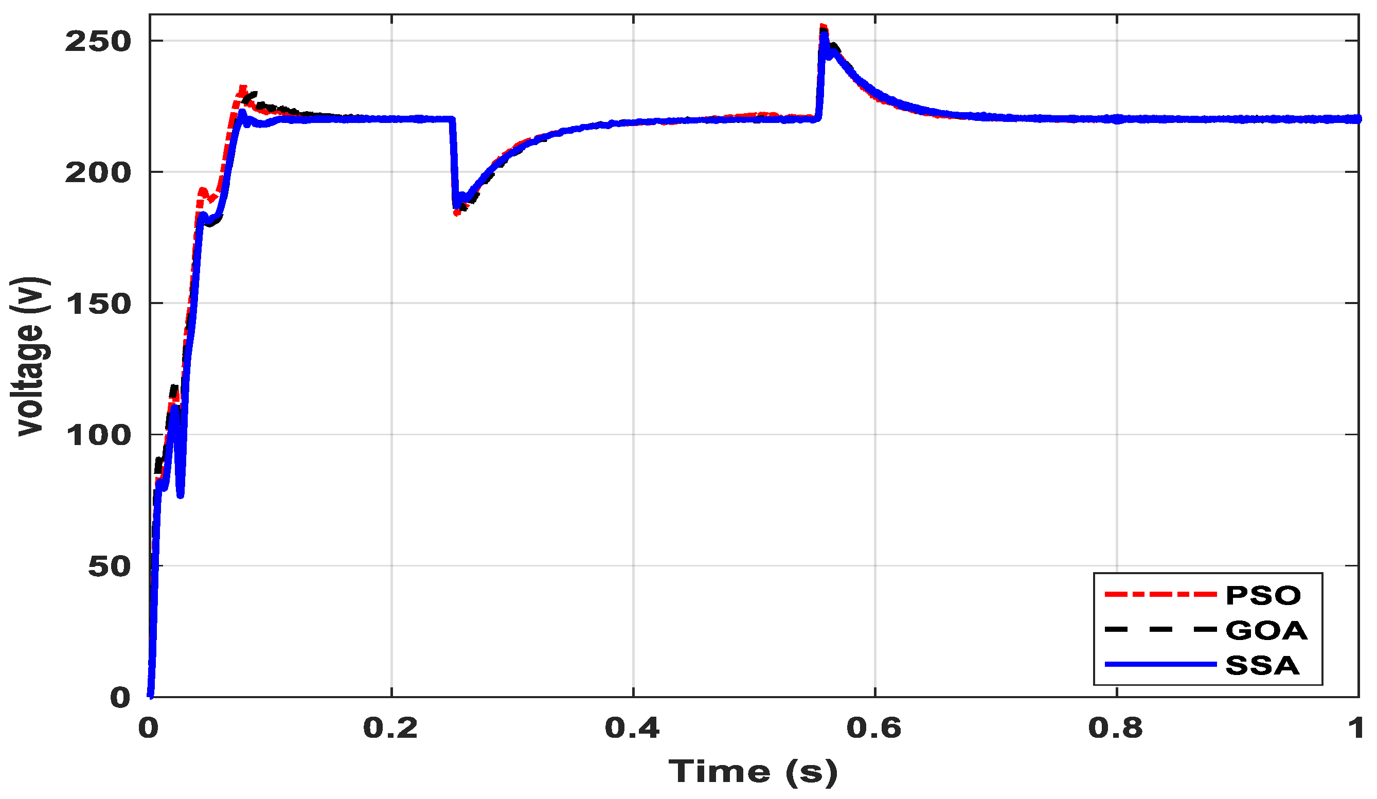
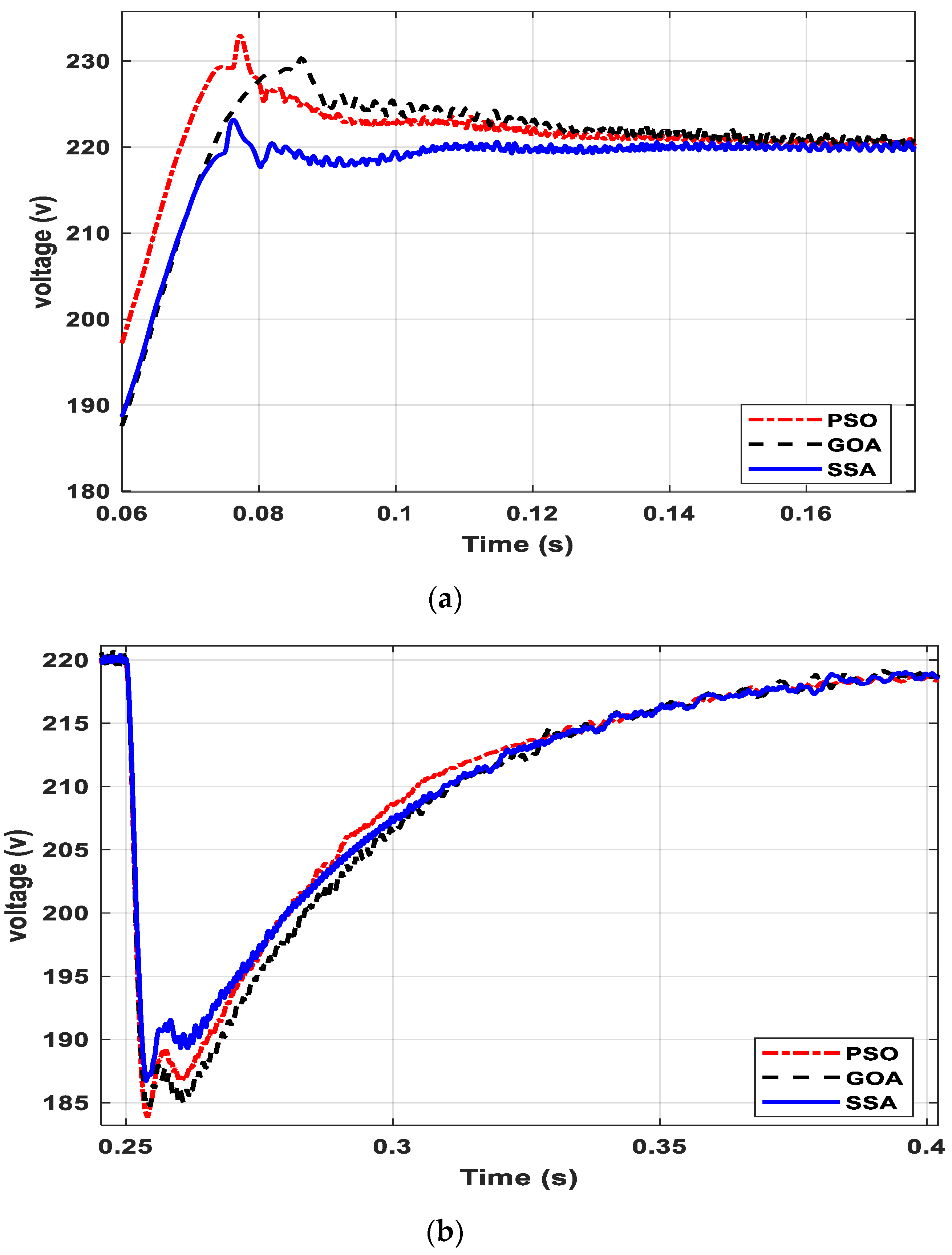
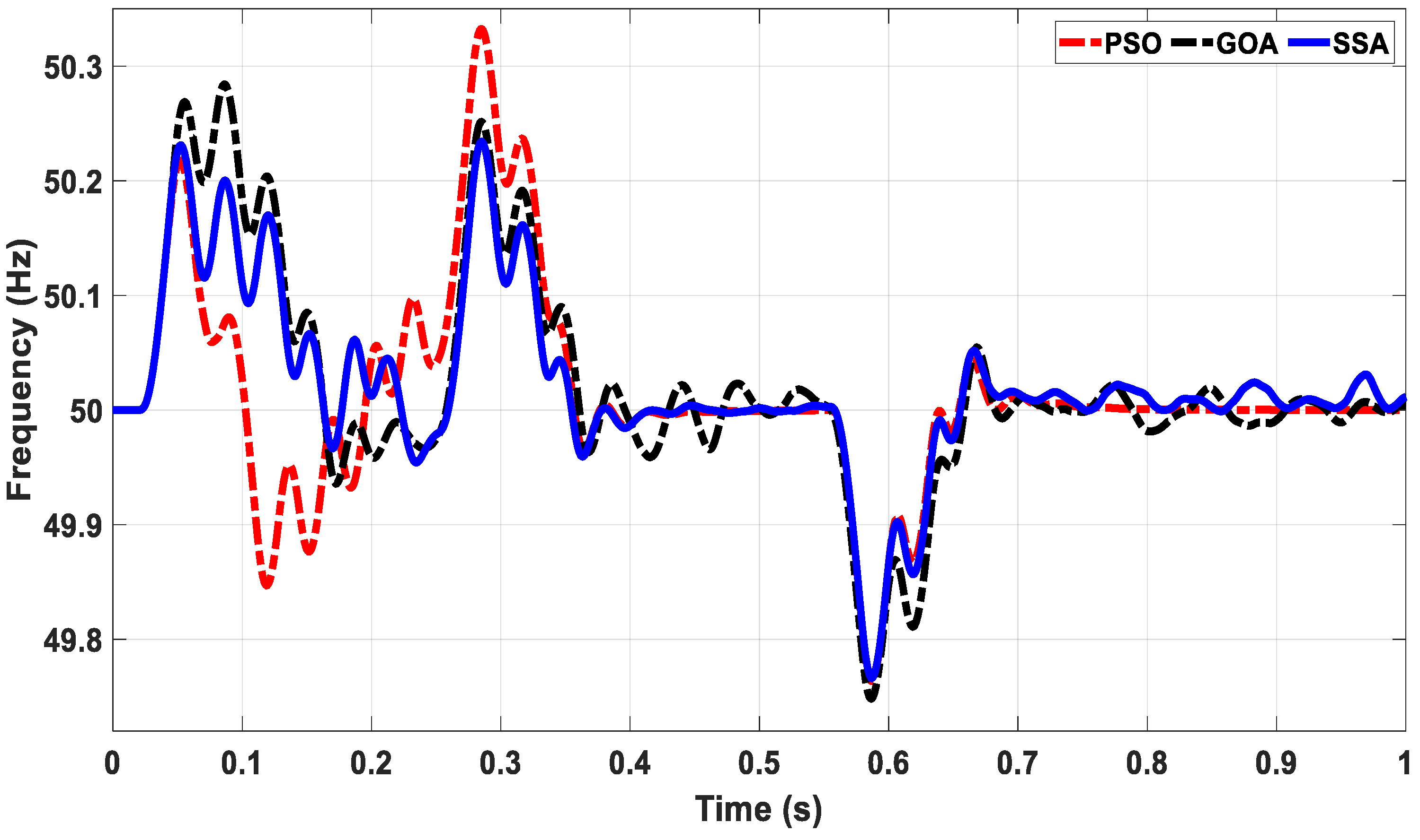
5.1. Voltage and Frequency Regulation during DG Insertion and Load Change

As discussed earlier, the regulation of voltage and frequency is one of the major control concerns in any islanded MG due to the absence of support from the main grid. Achieving a stable rated voltage and frequency after the DG insertion and abrupt load changes with minimum overshoot and settling time needs fine-tuning of the system parameters. Hence, three different metaheuristic techniques, i.e., PSO, GOA and SSA, were utilized separately to obtain the optimal set of PI parameters and dc-link capacitance in order to minimize the overshoot and settling time after a disturbance in the MG system. Once the simulation started from the MATLAB editor, the SSA initiated its searching process for the most suitable PI gains and capacitance combination that delivers the least value of FF in order to achieve optimal dynamic response with least possible overshoot and settling time. It simulates the developed SIMULINK MG model for the pre-set number of iterations. Finally, at the end of the simulation, optimal values of four PI gains along with the capacitance value were obtained that provided minimum error integrating the FF value, which in turn guarantees the optimal dynamic behavior of the developed MG model. At exactly 0.05 s, the solar PV modules were switched on through a three-phase CB. Once the DGs were injected into the power system, they caused overshoots in the system voltage, as depicted in Figure 6.
It may be noted from Figure 6 that the system voltage observed an overshoot during the DG insertion at 0.05 s of simulation. The magnitude of the overshoot depended on the DG rating as well as the selection of controller parameters. In order to have a fair comparison between the three optimal parameter selection methods, i.e., PSO, GOA and SSA, the DG rating and other system parameters were taken identical for all three cases. At 0.25 s of the simulation, a load of 40 kW, 20 kVAR was added to the system, and as a result of that, the system voltage observed a dip in voltage. Similarly, at 0.55 s, the load-3 was disconnected from the system. The corresponding response shows a swell in voltage at the mentioned simulation time. A zoomed version of Figure 6 during DG injection, load injection and load detachment is shown in Figure 7a–c, respectively.
It is obvious from Figure 7a–c that the optimal parameters obtained by the SSA optimization method provide better results compared to PSO and GOA in terms of overshoot and settling time for all three studied conditions. Another parameter that needs to be regulated during the islanded mode of MG operation is the frequency of the system. The frequency response of the system for PSO, GOA and SSA based MG system is shown in Figure 8.
Figure 8 shows the frequency response of the MG system for all three optimization methods. The result shows that all the metaheuristic methods provide a stable system frequency response within the allowable deviation range (±1%). However, the SSA based MG provides a better dynamic response as compared to its compotators. Table 3 shows a comparative analysis of all the studied methods for the voltage and frequency regulation of the studied islanded MG.
It may be noted from Table 3 that the SSA based controller provided better results for the most important dynamic response indicators as compared to PSO and GOA based controllers for the same operating conditions. Furthermore, it provided the most stable operation of the studied MG system and maintained the voltage within ±5% and frequency within ±1% of their nominal values, and hence, satisfied the IEEE standards. It is important to note that the settling time for the frequency is not provided. This is due to the reason that the frequency curve did not cross the ±2% of the rated value, and hence, settling time calculation is not applicable in this case.

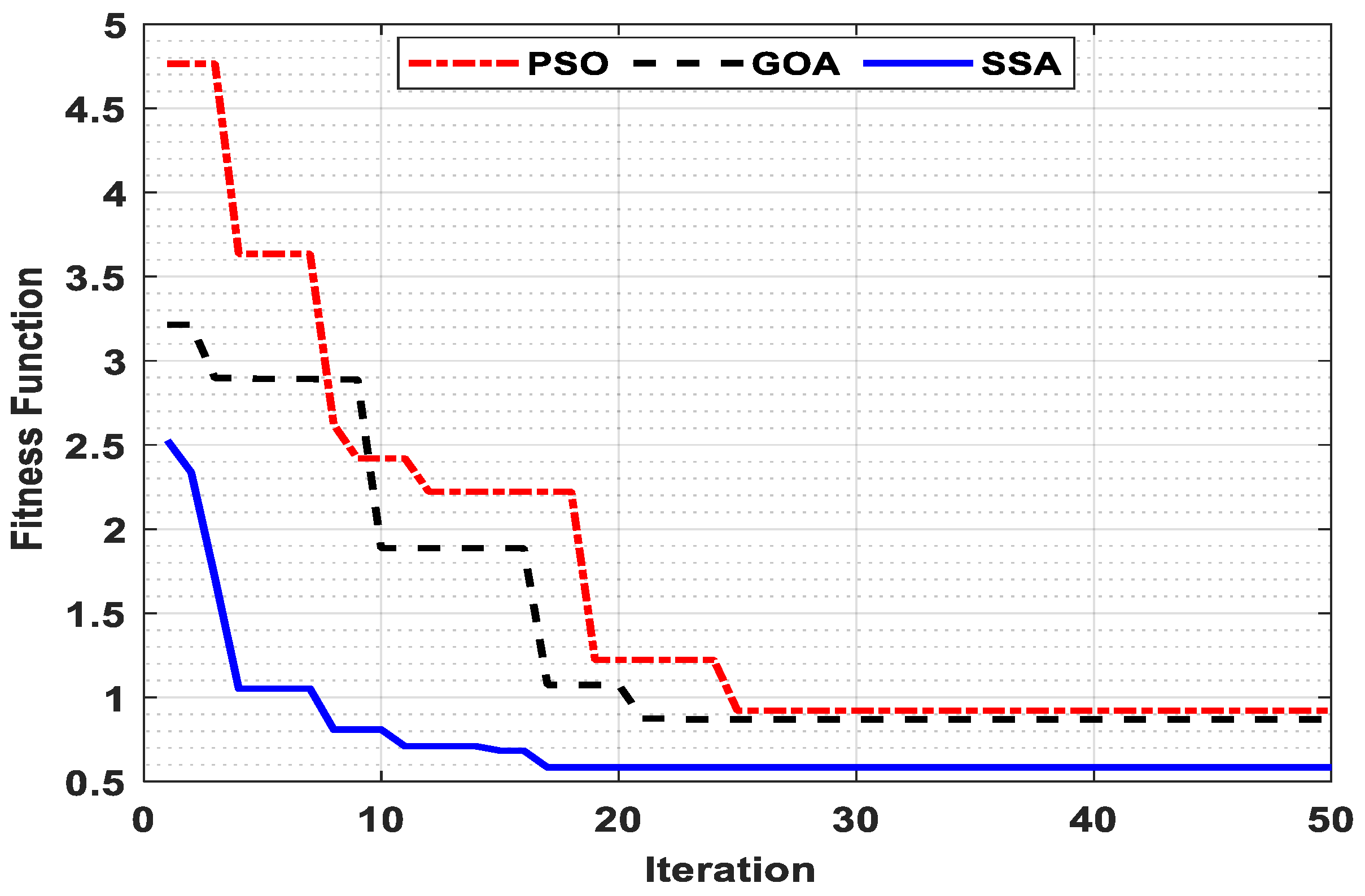
5.2. Performance Evaluation of Studied Optimization Algorithms

In this section, the results obtained from the performance evaluation of the studied optimization algorithms are presented. Three different optimization algorithms, namely PSO, GOA and SSA, were tested to minimize the stated fitness function under identical operating conditions and system parameters. Furthermore, in order to carry out a fair comparison among the mentioned algorithms, all algorithms were tested for an identical number of iterations, i.e., 50 iterations, and number of search agents, i.e., 50 number of search agents. Since all the metaheuristic algorithms were initiated by spreading the search agents randomly in the bounded search area, the current study was tested for 20 simulation runs for each algorithm and the best (minimum) fitness function values were adopted for comparison. The convergence curve for the tested algorithms is shown in Figure 9.
It can be seen from Figure 9 that the SSA achieves the least value of fitness function (0.5840618) in the 17th iteration, whereas for the PSO and GOA the least magnitude obtained was recorded as 0.9211586 and 0.8748774 in the 21st and 25th iteration, respectively. Hence, the SSA converges faster and provides a higher quality of solution as compared to its competitors.

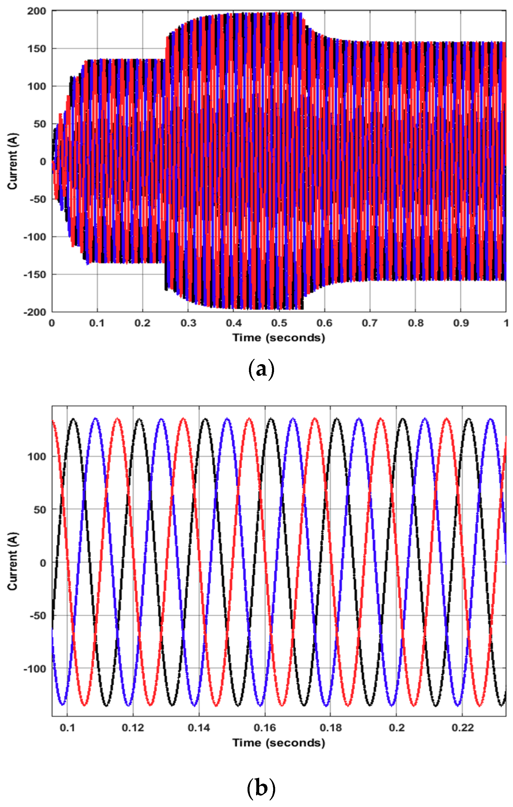
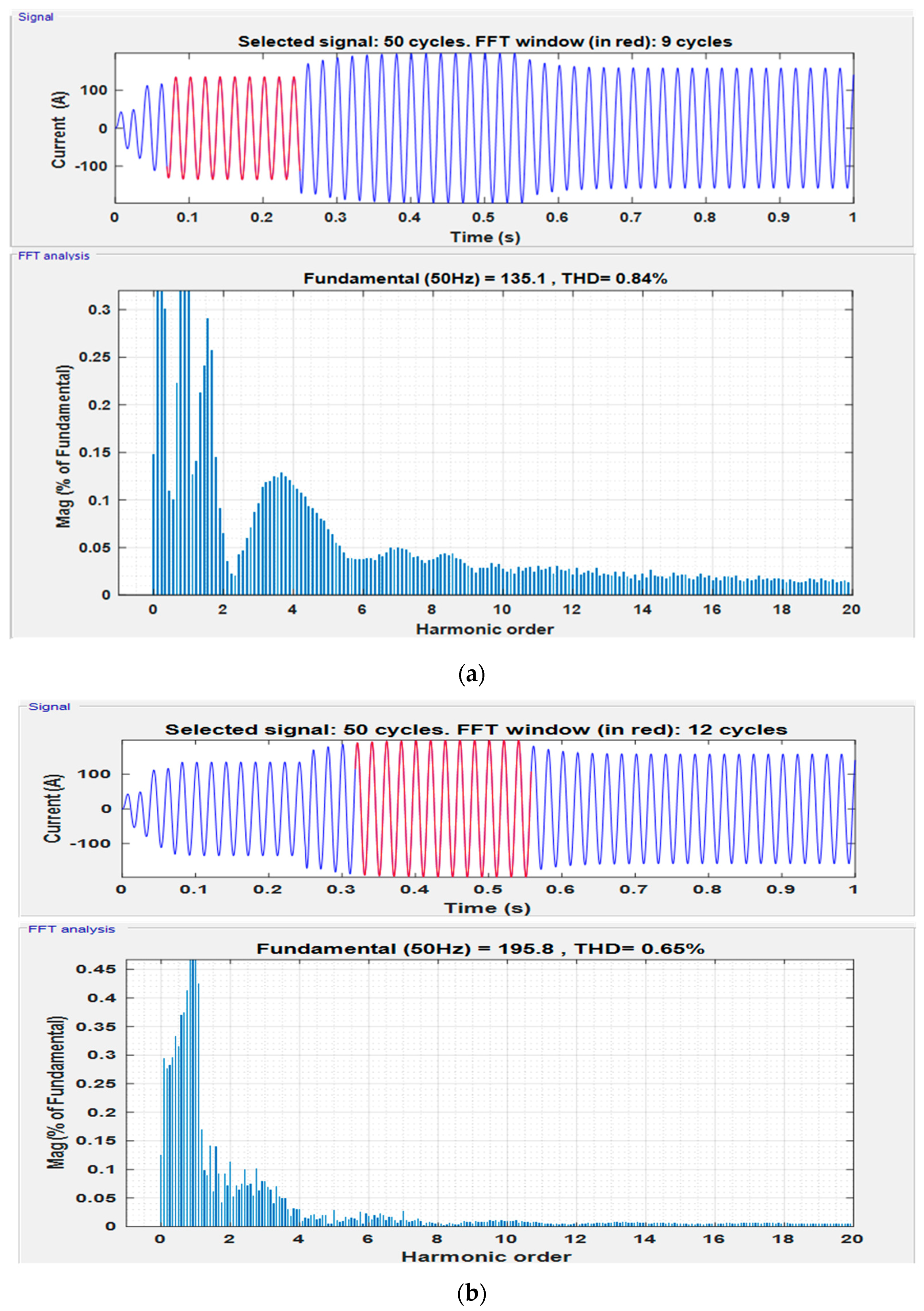
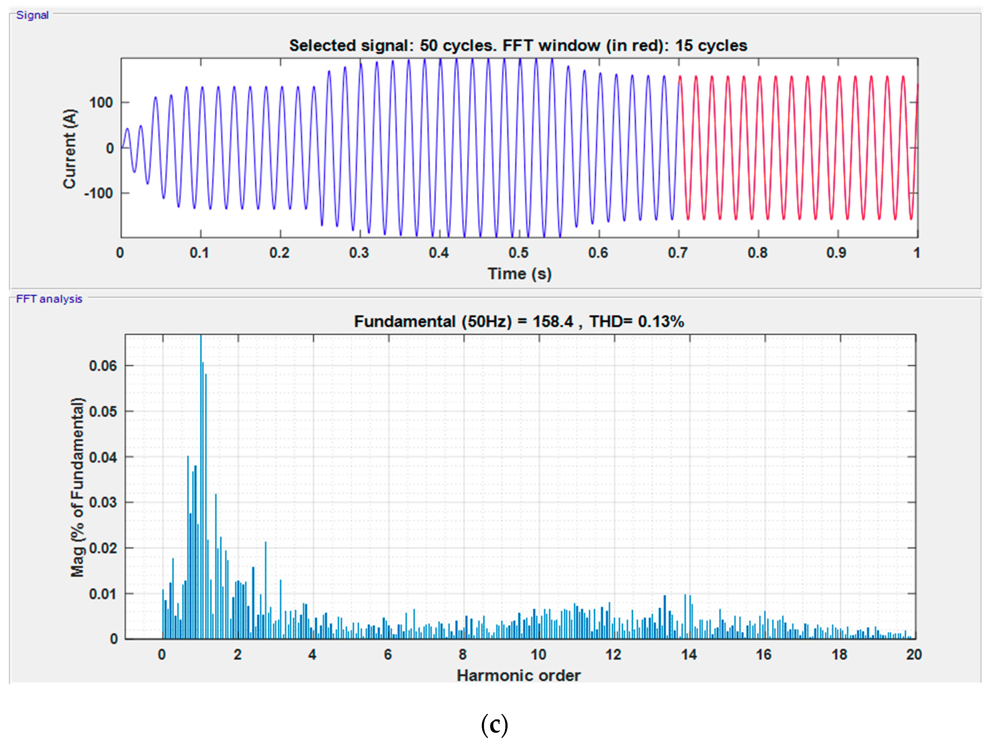
5.3. Power Quality Analysis

Due to the presence of non-linear power electronic devices like VSI and absence of the utility grid, maintaining the power quality and hence sinusoidality of the supply voltage and current is a very challenging task. A proper control architecture with optimal parameters can ensure pure sinusoidal voltage and current waveforms along with the high-power quality in such cases. The three-phase output current waveform for the studied system during all studied conditions is shown in Figure 10a, while its zoomed version from 0.1 to 0.22 s of simulation run is given in Figure 10b.
It can be seen from Figure 10 that the solar PV dc output current is inverted into almost pure sinusoidal waveform by the proposed controller with the least possible distortion. Furthermore, to analyze the harmonic contents present in the obtained current waveform, the Fast Fourier Transform (FFT) analysis has been carried out for all three operating conditions of the system and the results are depicted in Figure 11.
It is clear from the FFT analysis of the studied power system that the SSA based controller duly satisfies the power quality standards set by IEEE 1547–2003 [17]. The results from Figure 11 are explained in tabular form in Table 4.
It is obvious from Figure 11 and Table 4 that the proposed controller provides a high quality of power supply under all studied operating conditions and provides pure sinusoidal waveform, which shows the effectiveness of the proposed controller in maintaining optimal transient response with high power quality.

6. Conclusions

In this paper, an optimal controller for islanded MG has been successfully developed using the intelligence of SSA. The developed controller has successfully maintained the voltage and frequency at their nominal values with minimum possible overshoot and settling time during MG injection and load change conditions. The convergence behavior of the studied optimization algorithms proved that the SSA offers a higher quality of solution and faster optimization capabilities as compared to its counterpart optimization algorithms. Furthermore, the results from the power quality analysis show that the developed controller achieves high power quality and maintained almost perfect sinusoidal waveform of the voltage and current. The outcomes of the proposed controller were compared with that of the PSO and GOA based controller for the same operating conditions and system configuration. The results show that the SSA based parameter selection provides an optimal dynamic response during all studied conditions and has superior performance as compared to its competitors.

Author Contributions

Each author has contributed significantly. The first and the corresponding author has initiated the idea and carried out the simulations along with preparation of the initial draft. The second author (M.W.M.) supervised the whole project and made significant corrections in the initial version of the article. M.M.R. has reviewed the article and helped in validation process. W.A. and S.A. helped in software and writing the revised version of the article respectively.

Funding

No funding was opted for this project.

Conflicts of Interest

The authors declare no conflict of interest.

List of Symbols

SymbolName
C f Low pass filter capacitance
K 1 1 : n initial positions of the salps
K j 1 Position of leader salp
L f Low pass filter inductance
M i Location of the food source in the jth dimension
R f Low pass filter resistance
V g Grid voltage
e f Frequency error
e v Voltage error
f * Reactive frequency
f n Nominal frequency
i a b c Three-phase current
i d * Direct reference current
i q * Quadrature reference current
k v Droop constant for voltage
k w Droop constant for frequency
l b j Lower bound of search boundary
u b j Upper bound of search boundary
v * Reference voltage
v a b c Three-phase voltage
v d * Direct reference voltage
v n Nominal or rated voltage
v q * Quadrature reference voltage
v α , v β Reference voltage in αβ frame
aAcceleration of the leading salp
iSalp number
Cdc-link capacitance
c1, c2, c3Random numbers
Kpf, KifGains for the lower arm PI controller
Kpv, KivGains for the upper arm PI controller
lNumber of iterations
LNumber of maximum iterations
MFood source position
ƟReference angel
pActive power
qReactive power
randRandom number
tTotal simulation time
ω Angular frequency
ω c Filter cut-off frequency
v 0 Initial velocity of leading salp

References

  1. Hatziargyriou, N. Microgrids: Architectures and Control; John Wiley & Sons: Chichester, UK, 2014. [Google Scholar]
  2. Jumani, T.A.; Mustafa, M.W.; Rasid, M.M.; Mirjat, N.H.; Baloch, M.H.; Salisu, S. Optimal Power Flow Controller for Grid-Connected Microgrids using Grasshopper Optimization Algorithm. Electronics 2019, 8, 111. [Google Scholar] [CrossRef]
  3. Mirjalili, S.; Gandomi, A.H.; Mirjalili, S.Z.; Saremi, S.; Faris, H.; Mirjalili, S.M. Salp Swarm Algorithm: A bio-inspired optimizer for engineering design problems. Adv. Eng. Softw. 2017, 114, 163–191. [Google Scholar] [CrossRef]
  4. Abbassi, R.; Abbassi, A.; Heidari, A.A.; Mirjalili, S. An efficient salp swarm-inspired algorithm for parameters identification of photovoltaic cell models. Energy Convers. Manag. 2019, 179, 362–372. [Google Scholar] [CrossRef]
  5. Tolba, M.; Rezk, H.; Diab, A.; Al-Dhaifallah, M. A novel robust methodology based Salp swarm algorithm for allocation and capacity of renewable distributed generators on distribution grids. Energies 2018, 11, 2556. [Google Scholar] [CrossRef]
  6. El-Fergany, A.A. Extracting optimal parameters of PEM fuel cells using Salp Swarm Optimizer. Renew. Energy 2018, 119, 641–648. [Google Scholar] [CrossRef]
  7. Abusnaina, A.A.; Ahmad, S.; Jarrar, R.; Mafarja, M. Training neural networks using salp swarm algorithm for pattern classification. In Proceedings of the 2nd International Conference on Future Networks and Distributed Systems, Amman, Jordan, 26–27 June 2018; p. 17. [Google Scholar]
  8. Kumari, S.; Shankar, G. A Novel Application of Salp Swarm Algorithm in Load Frequency Control of Multi-Area Power System. In Proceedings of the 2018 IEEE International Conference on Power Electronics, Drives and Energy Systems (PEDES), Chennai, India, 18–21 December 2018; pp. 1–5. [Google Scholar]
  9. Al-Saedi, W.; Lachowicz, S.W.; Habibi, D.; Bass, O. Voltage and frequency regulation based DG unit in an autonomous microgrid operation using Particle Swarm Optimization. Int. J. Electr. Power Energy Syst. 2013, 53, 742–751. [Google Scholar] [CrossRef]
  10. Vinayagam, A.; Alqumsan, A.A.; Swarna, K.; Khoo, S.Y.; Stojcevski, A. Intelligent control strategy in the islanded network of a solar PV microgrid. Electr. Power Syst. Res. 2018, 155, 93–103. [Google Scholar] [CrossRef]
  11. Moarref, A.E.; Sedighizadeh, M.; Esmaili, M. Multi-objective voltage and frequency regulation in autonomous microgrids using Pareto-based Big Bang-Big Crunch algorithm. Control Eng. Pract. 2016, 55, 56–68. [Google Scholar] [CrossRef]
  12. Sedighizadeh, M.; Esmaili, M.; Eisapour-Moarref, A. Voltage and frequency regulation in autonomous microgrids using Hybrid Big Bang-Big Crunch algorithm. Appl. Soft Comput. 2017, 52, 176–189. [Google Scholar] [CrossRef]
  13. Qazi, S.H.; Mustafa, M.W.; Sultana, U.; Mirjat, N.H.; Soomro, S.A.; Rasheed, N. Regulation of Voltage and Frequency in Solid Oxide Fuel Cell-Based Autonomous Microgrids Using the Whales Optimisation Algorithm. Energies 2018, 11, 1318. [Google Scholar] [CrossRef]
  14. Jumani, T.A.; Mustafa, M.W.; Rasid, M.M.; Mirjat, N.H.; Leghari, Z.H.; Saeed, M.S. Optimal Voltage and Frequency Control of an Islanded Microgrid using Grasshopper Optimization Algorithm. Energies 2018, 11, 3191. [Google Scholar] [CrossRef]
  15. Killingsworth, N.; Krstic, M. Auto-tuning of PID controllers via extremum seeking. In Proceedings of the American Control Conference, Portland, OR, USA, 8–10 June 2005; pp. 2251–2256. [Google Scholar]
  16. Seborg, D.E.; Edger, T.F.; Mellichamp, D.A. Process Dynamics and Control, 2nd ed.; John Wiley & Sons: Chichester, UK, 2004. [Google Scholar]
  17. Association, I.S. IEEE 1547 Standard for Interconnecting Distributed Resources with Electric Power Systems; IEEE Standards Association: Piscataway, NJ, USA, 2003. [Google Scholar]
Figure 1. A basic structure of Microgrid [2].
Processes 07 00840 g001
Figure 2. A generalized control structure for MGs.
Processes 07 00840 g002
Figure 3. Studied islanded MG with power and control architecture.
Processes 07 00840 g003
Figure 4. Detailed diagram of the salp swarm optimization algorithm based controller for islanded MG.
Processes 07 00840 g004
Figure 5. Proposed SSA based optimal plus integral (PI) parameter selection in studied islanded MG.
Processes 07 00840 g005
Figure 6. The voltage response of the system during DG insertion and load change.
Processes 07 00840 g006
Figure 7. Voltage profile at (a) DG insertion (b) abrupt Load increment (c) abrupt load decrement.
Processes 07 00840 g007aProcesses 07 00840 g007b
Figure 8. The frequency response of the MG system for the studied optimization methods.
Processes 07 00840 g008
Figure 9. Convergence profile for PSO, GOA and SSA.
Processes 07 00840 g009
Figure 10. Three-phase sinusoidal current waveform (a) complete operation (b) zoomed version from 0.1–0.22 s.
Processes 07 00840 g010
Figure 11. FFT analysis of studied MG system during (a) DG injection, (b) load injection and (c) load detachment.
Processes 07 00840 g011aProcesses 07 00840 g011b
Table 1. Studied MG system parameters.
ParameterSymbolValue
Solar PV ratingPs150 kW
Filter capacitanceCf2.5 mF
Filter inductanceLf95 mH
Switching frequencyfsw10 kHz
Sampling frequencyfs500 kHz
Load 1Pl, Q150 kW, 30 kVAR
Load 2P2, Q240 kW, 20 kVAR
Load 3P3, Q340 kW, 20 kVAR
Table 2. The optimized parameters obtained at the end of the simulation.
OptimizationKpvKivKpfKifC (mF)
PSO0.257109325.63920190.93749059.384785223.817
GOA0.944155712.836585026.7686541.247457517.458
SSA1.54859630.873029752.138599215.58393219.954
Table 3. Dynamic response evaluation of the proposed controller for voltage and frequency regulation.
Studied ConditionMethodMaximum Overshoot/Undershoot (%)Peak Time (ms)Settling Time (ms)
VoltageMG insertionPSO5.8627.237.7
GOA4.6836.364.5
SSA1.4526.226.36
Load injectionPSO16.454.0094.21
GOA16.004.7094.20
SSA15.043.9094.19
Load detachmentPSO16.417.7073.50
GOA15.597.5078.50
SSA14.777.8077.40
FrequencyMG injectionPSO0.442.05-
GOA0.545.58-
SSA0.462.30-
Load injectionPSO0.6635.2-
GOA0.5034.8-
SSA0.4635.0-
Load detachmentPSO0.5036.4-
GOA0.4836.7-
SSA0.4636.8-
Table 4. FFT analysis understudied operating conditions.
Operating ConditionPercentage Harmonics (%)
MG injection0.84
Load injection0.65
Load detachment0.13

