Article

Energetic Analysis of Different Configurations of Power Plants Connected to Liquid Chemical Looping Gasification

1
School of Mechanical Engineering, University of Adelaide, Adelaide, SA 5005, Australia
2
Department of Civil and Environmental Engineering, Florida International University, Miami, FL 33174, USA
3
Department of Electrical Engineering, College of Engineering, King Saud University, P.O. Box. 800, Riyadh 11421, Saudi Arabia
4
Department of Electrical Engineering, Faculty of Energy Engineering, Aswan University, Aswan 81528, Egypt
5
Sustainable Management of Natural Resources and Environment Research Group, Faculty of Environment and Labour Safety, Ton Duc Thang University, Ho Chi Minh City, Vietnam
*
Author to whom correspondence should be addressed.
Processes 2019, 7(10), 763; https://doi.org/10.3390/pr7100763
Submission received: 22 September 2019 / Revised: 13 October 2019 / Accepted: 15 October 2019 / Published: 18 October 2019
(This article belongs to the Special Issue Thermodynamics: Modeling and Simulation)

Abstract

:
In this article, a thermodynamic study was conducted on the energetic and exergy performance of a new configuration of liquid chemical looping gasification (LCLG) plant integrated with a power block to assess the overall performance of the system including exergy partitioned in syngas and first law efficiency (FLE). LCLG is a relatively new concept for the production of high-quality synthetic gas from solid feedstock such as biomass. As the temperature and pressure of the looping system are high, there is thermodynamic potential to co-produce chemical products, power and heat. Hence, in the present work, three different configurations of a power cycle were thermodynamically assessed. In the first proposed power cycle, the produced syngas from the gasifier was combusted in a combustion chamber and the exhausted gases were fed into a gas turbine. In the second and third proposed power cycles, the hot air was directly fed into a gas turbine or was used to produce steam for the steam turbine combined cycle. The processes were simulated with Aspen Plus and Outotec HSC chemistry software packages. The influence of different operating parameters including temperature and pressure of the air reactor and type of oxygen carrier on the first law and exergy efficiency (exergy partitioned in synthetic gas) was assessed. Results showed that the FLE for the proposed gas turbine and steam turbine combined cycles was ~33% to 35%, which is within the range of the efficiency obtained for the state-of-the-art power cycles reported in the literature. Results also showed that lead oxide was a suitable oxygen carrier for the LCLG system, which can be integrated into a steam turbine combined cycle with an FLE of 0.45, while copper oxide showed an FLE of 0.43 for the gas turbine combined cycle.

1. Introduction

In recent years, syngas production using gasification has received special attention as coal will continue to remain the dominant source of energy production due to its lower price and availability in comparison with other fuels [1,2]. Chemical looping gasification is a promising technology for converting carbonaceous fuel into syngas by means of looping the solid oxygen carrier between the air reactor (AR) and the fuel reactor (FR) [3,4,5,6,7]. Generally, metal oxides are employed as the oxygen carrier and they are reduced in the fuel reactor and are successively oxidized in the air reactor.
Oxidation and reduction of metal oxides in a chemical looping system occur at high-temperature conditions resulting in morphological changes of particles. In addition, agglomeration and sintering are other issues, which decrease the lifetime and operability of the particles in the system [8]. Recently, Sarafraz and his co-workers have proposed the use of liquid metals instead of solid metal oxides to improve the thermal performance and chemical efficiency of the chemical looping gasification system [9,10]. They have shown that if the rate of oxygen in the system is limited to sub-stoichiometric quantities, the proposed system works as a chemical looping gasification. This brings immense benefits to syngas production technology as it controls the amount of carbon dioxide production, avoiding the appearance of nitrogen in the product, which addresses the nitrogen dilution problem. Moreover, the outlet air from the air reactor can also be used in a gas turbine combined cycle to increase the overall thermodynamic efficiency of the system by producing work.
Integrated gasification combined cycle coupled with chemical looping combustion (IGCC–CLC) and direct coal chemical looping combustion (CDCLC) for generating electricity from carbonaceous fuel has extensively been studied in the literature [11,12,13,14]. In this type of chemical looping combustion (CLC) system, coal is used as a feedstock and is mixed with a solid oxygen carrier such as carbonates or metal oxides. The produced syngas can later be burnt in an after-burner to produce hot gas for gas turbine combined cycle. Since coal is a low-grade feedstock, the syngas produced in the gasifier has higher ratio of hydrogen to CO due to the presence of steam. Steam is normally used in CDCLC to maintain the temperature and provide sufficient mixing between the oxygen carrier and coal particles. Despite a relatively good heat and mass transfer rate in the fluidised bed gasifier, the presence of ash and heavy metals in the structure of the coal affects the purity and reaction sites on the oxygen carrier particles. Hence, CDCLC is extensively investigated to improve its thermal and energetic efficiency. It is worth mentioning that in most studies, the produced syngas is partially filtered as well to coproduce hydrogen and electricity [3], or fully combusted to generate electricity only [13,15]. In some investigations on the integrated gasification combined cycle (IGCC) working with biomass, it has been demonstrated that biomass fuel in large quantities causes some problems, which limit the use of large scale biomass systems for steam cycles or integrated gasification combined cycles. These problems include low efficiency, environmental pollution and complexity in kinetics and reactor design. Thus, solid biomass is yet to be commercialized in an IGCC system and can only be used in small-scale conventional plants [16,17]. The rate of carbon dioxide production and its sequestration in IGCC systems connected to CLC systems is another challenge [18,19,20,21], however, it is beyond the scope of the present research.
CLC systems working with solid oxygen carriers have encountered the challenge over the limited application of solid particles in the system, as they are sintered, deformed and agglomerated at high temperatures and pressure conditions. In addition, oxy-fuel combustion systems require an air separation unit, which is energy-intensive. In addition, for controlling the temperature of the flame to prevent from NOx formation (due to the presence of nitrogen fuel) in oxy-fuel combustion, carbon dioxide is partly recycled into the system to decrease the temperature, which reduces the quality of the product and efficiency of the carbon sequestration process. While liquid chemical looping gasification (LCLG) offers a potential approach for solving the nitrogen dilution problem, sintering and agglomeration challenge solid particle oxygen carriers and effective ash separation for carbonaceous fuel.
In light of above, the main aim of the present work is to assess the thermodynamic potential of the liquid chemical looping gasification process for the co-production of synthetic fuel and electricity through integration with power blocks. Thus, in the present work, different configuration of power blocks including gas turbine, steam turbine and integrated gasification combined cycles were connected to an LCLG with the view to assess the first law efficiency and exergy partitioned into the synthetic fuel. The effect of operating parameters such as pressure and temperature of the LCLG gasification reactor on the first law efficiency of the system was thermodynamically assessed and discussed. To the best of our knowledge, there are no investigations on the integration of power block and liquid chemical looping gasification systems. Hence, the results of this study contribute to the state of the art area of chemical looping integrated processes.

2. Materials and Methods

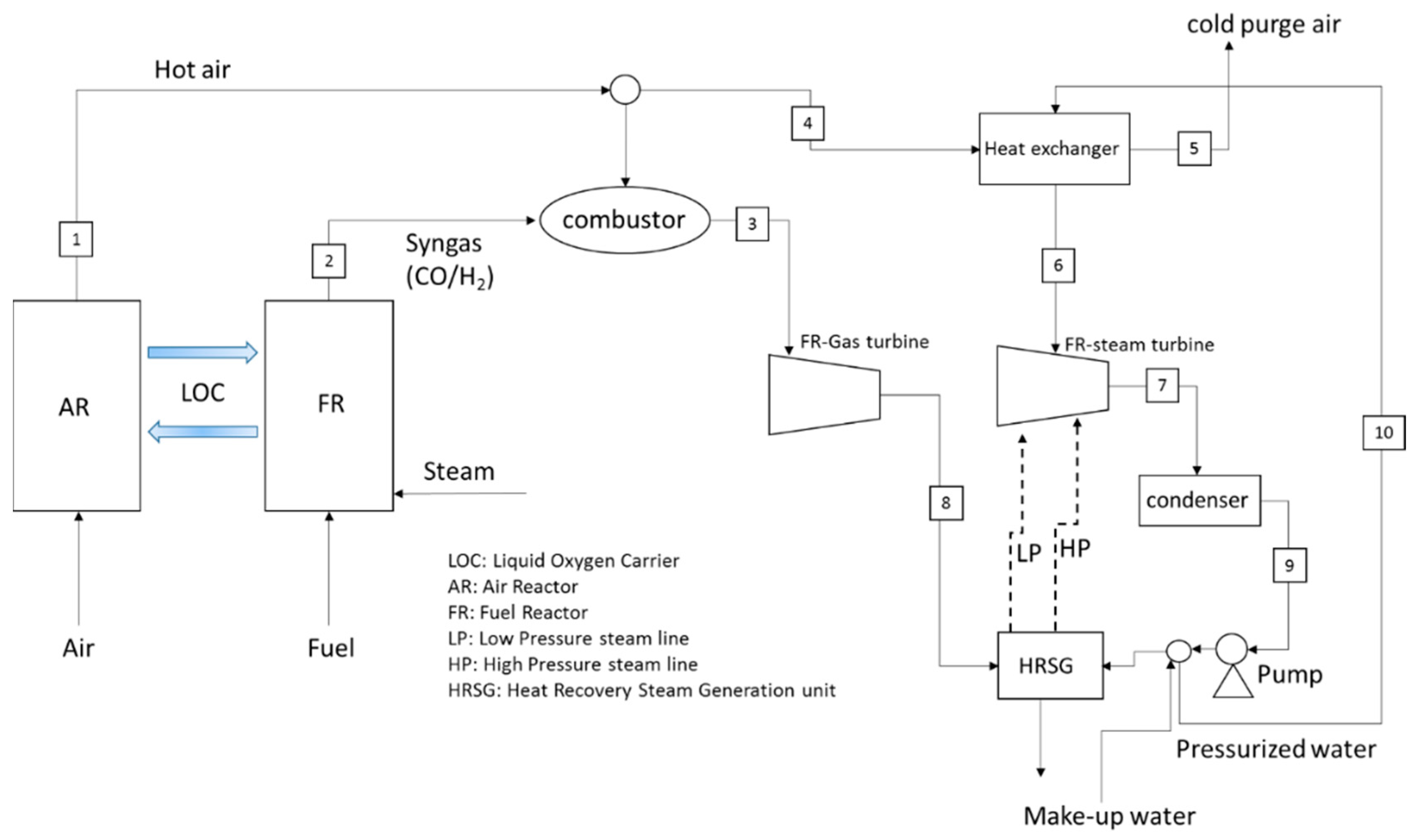
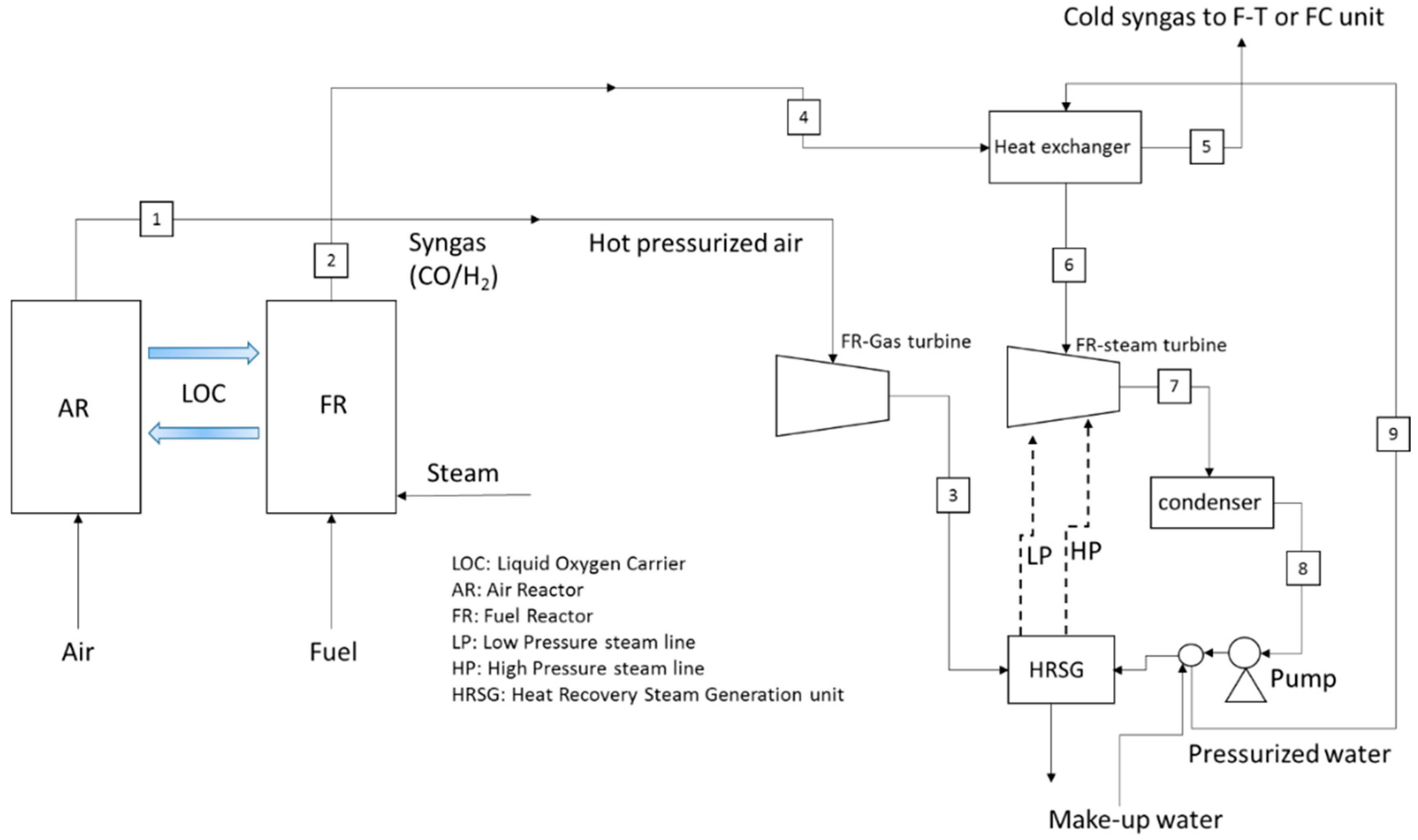
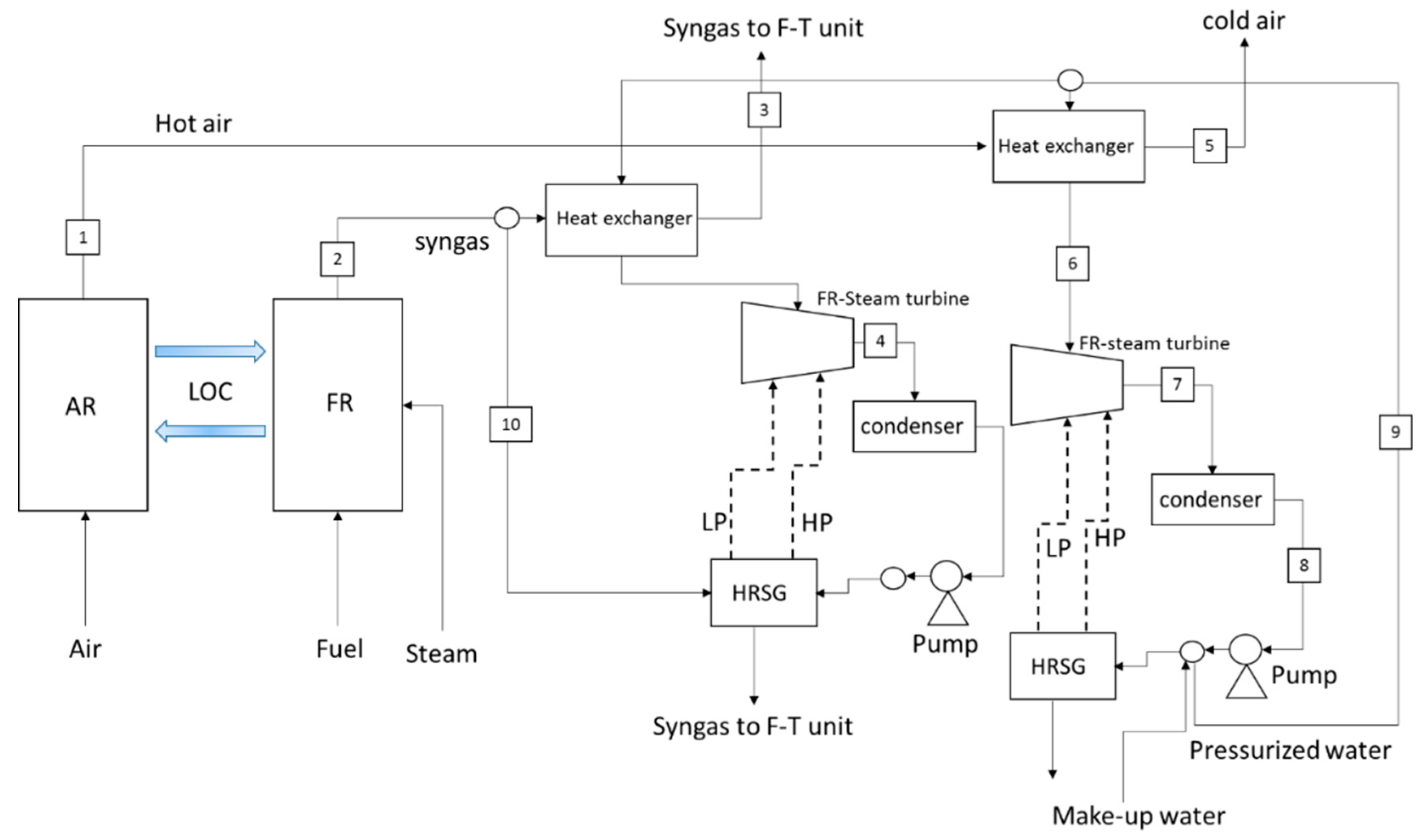
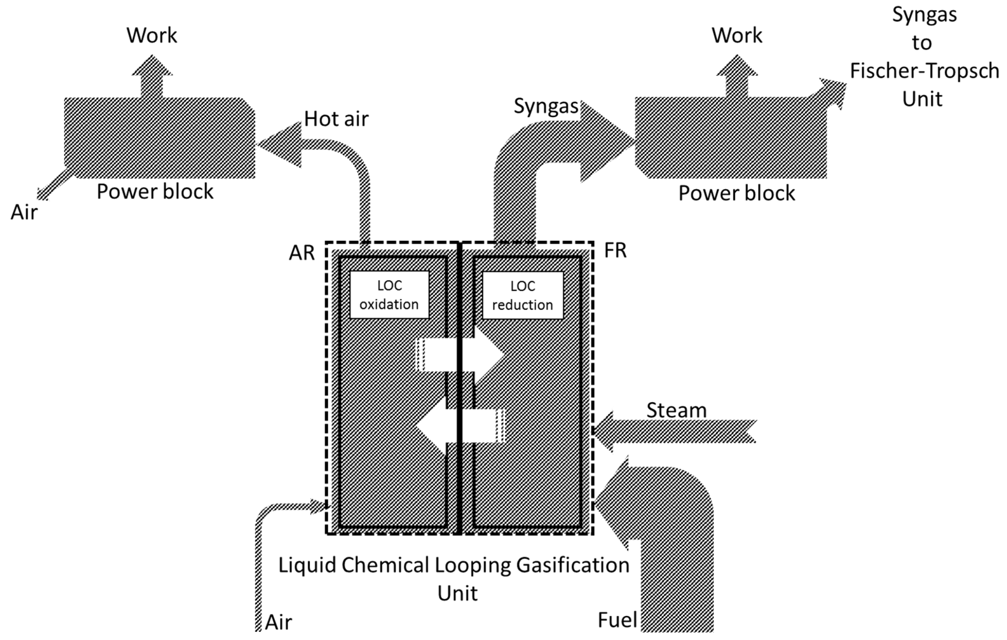
2.1. LCLG Syngas Production Plant and Power Blocks

Figure 1 shows the schematic diagram of a configuration of the LCLG system incorporated in a gas turbine combined cycle (GTCC). In this power cycle, the produced syngas from the LCLG system was combusted at high pressure and temperature in a combustion chamber, and the product gases were transported to a gas turbine to produce the work. Depending on the quality of syngas produced from the LCLG system, heat load and quantity of exhausted gas varied which directly influenced the exergy and produced work of the power cycle. The outlet gas from the gas turbine was fed into a heat recovery steam generation (HRSG) unit to produce high pressure, (HP) (60 bar) and low pressure (LP) (5 bar) steam lines, which both were fed into a steam turbine to produce more work. Outlet air from the air reactor was separately utilized for heating a high-pressure water line to produce the steam for the steam turbine and the cold air was released into the atmosphere. The high-pressure steam (600 °C and 60 bar) produced by the heat recovery steam generation unit was fed to the 4-stage steam turbine (FR-steam turbine). An optional water make-up line was also considered to compensate the water inside the loop in case of evaporation or any leakages. For this study, this line was neglected for mass and energy balances as the water/steam loops were closed.
Figure 2 shows the gas turbine combined cycle power plant connected to the LCLG system. In this configuration of the power block, the outlet from the air reactor was directly fed into the gas turbine. Therefore, temperature and pressure of the air reactor had to be sufficiently high to be used in the gas turbine (GT). Hence, as will be discussed later, copper oxide can be used in the LCLG system, which can work at temperatures and pressures as high as 1300 °C and 10 bar, respectively. The produced syngas from the LCLG system was fed into the heat exchanger to be cooled and discharged downstream for further applications in a Fischer–Tropsch unit. A high-pressure water line was also fed into the heat exchanger for producing high temperature and pressure steam for the steam turbine. The outlet stream from the gas turbine and steam turbine were transported into a heat recovery steam generation (HRSG) unit for producing low and high-pressure steam to be fed into the steam turbine and to enhance the efficiency of the power cycle.
For the third power cycle, as shown in Figure 3, syngas was first cooled by a high-pressure line of water to produce the steam for steam turbine combined cycle (STCC) and the cooled syngas was used in a Fischer–Tropsch unit. The hot air was also used for producing the steam to be fed into the steam turbine. For this power cycle, two outlets in the Fischer–Tropsch were considered, the outlet from the heat exchanger and the outlet stream from the HRSG (LP/HP: 10/85 bar, respectively). Another HRSG unit was also employed with different heat loads to produce low and high-pressure steam lines (5 and 60 bar, respectively).

2.2. Simulation of the LCLG and Power Plants

Simulations of the power plants were performed using the Aspen Plus software package. The modelling involved the solution of coupled governing equations of energy and mass. Three different thermodynamic equations of state including non-ideal Peng–Robinson, Uniquac and Non-Random Two Liquid (NRTL) were employed to predict the thermo-physical properties of the compounds and it was found that results were in a good agreement—within 1.1% deviation against themselves. Therefore, non-ideal Peng–Robinson was selected to be used for the simulation as previously introduced by [22]. The power generated or consumed by the pump, gas and steam turbines was computed assuming that all the systems were isentropic with a constant isentropic efficiency [23]. For pressurising the LCLG reactors, the work required by compressors were separately estimated and considered as the auxiliary work. For the LCLG section, simulations were performed using HSC chemistry software using Gibbs minimization method to analyse the equilibrium composition of the products in air and fuel reactors. Two different metal oxides were considered for the study namely copper and lead oxides. In order to obtain the appropriate operating condition, solid/liquid phase diagrams of the materials were used.

2.3. Operating Regime of the LCLG

Figure 4 presents the phase diagram of copper and oxygen as a function of temperature and pressure. Within the region specified by blue colour (Region 1), a homogenous liquid slag formed from Cu (l), CuO (l) and Cu2O (l) over the range of mass fractions of oxygen from 0.01 to 0.5. For the oxygen mass fractions from 0.01 to 0.33, the slag comprised Cu (l) and Cu2O (l), while for 0.33–5, Region 1 consisted of Cu2O (l) and CuO (l). For temperatures lower than 1384 °C and XO = 0.5, solid CuO was formed while at temperatures lower than 1232 °C and XO = 0.33, solid Cu2O was formed. Below the solidification line (boundary line between the blue and white zones), (two-phase Region 3), the slag comprised both the solid and liquid phases with unknown compounds of copper and oxygen. This regime was inappropriate for gasification because the two-phase condition led to unknown heat and mass transfer between the phases. Therefore, Region 1 was thermodynamically preferred for the gasification process.
Figure 5 shows the phase diagram of the lead oxide at different pressure and temperatures. As shown, it was clear that the region confined with the red rectangle (blue region) in between temperatures of 600 °C–900 °C was in the form of a liquid mixture comprising PbO and Pb, which was suitable for reduction and oxidation reactions in the LCLG system. Other regions mostly formed a two-phase solid/liquid molten lead, which was not meritorious for the LCLG system as the formation of solid material resulted in system failure.
To investigate the influence of different operating parameters on the energetic performance of the LCLG system, a sensitivity analysis was performed on the fuel reactor. For this purpose, a new parameter was defined as the ratio of liquid oxygen carrier (LOC) to the fuel as:
ϕ L O C = n ˙ L O C n ˙ f u e l
In which, n ˙ is the mole flow rate of the LOC and fuel. Quantity of the steam fed into the fuel reactor was a key parameter affecting the exergy and energetic performance of the system. Hence, another parameter was defined as the molar ratio of steam to fuel:
ϕ s t e a m = n ˙ s t e a m n ˙ f u e l
Here, n ˙ is the number of moles of the components for steam and fuel. To assess the exergy performance of the system, it was imperative to understand the quantity of exergy carried by syngas or exhausted gases. It was also assumed that there was no exergy destruction in the system, thus the total exergy of the system was obtained by Equation (3):
E x t o t a l = E x f u e l ( E x s y n g a s + E e x h a u s t e d g a s ) + Δ E x d e s t r u c t i o n
Exergy of the fuel, syngas and exhausted gases can be calculated using the following equations:
E x f u e l = n ˙ f u e l . L H V c a r b o n f u e l
In Equation (4), n ˙ is the mole flow rate of the fuel and Lower Heating Value of the fuel is shown with LHV. For syngas, exergy can be calculated as:
E x s y n g a s = n ˙ s y n g a s . L H V s y n g a s
where, n ˙ is the mole flow rate of the outlet syngas from the fuel reactor. The rest of the products leave the reactor as hot gases (exhaust gases), which carry a significant amount of energy as they are at high temperature and pressure. The exergy for exhausting gases can be obtained from Equation (6).
E x E x h a u s t e d g a s = n ˙ . L H V c a r b o n f u e l n ˙ . L H V s y n g a s
Ex is the exergy and n ˙ is the mole flow rate of the fuel (feedstock) and syngas.
The net produced work by the power block can be obtained from Equation (7):
W n e t = p r o d u c e d W c o n s u m p t i o n W = W G T + W S T W p u m p
where, W is the work generated by a gas turbine (WGT), or a steam turbine (WST) and Wpump is the work required for the operation of the pump(s). The first law efficiency (FLE) of the system can be expressed as the ratio of net obtained work from the system to the total input energy as given in Equation (8):
η = W n e t n ˙ f u e l . L H V c a r b o n f u e l
where W is the work generated by the power plant. The exergy efficiency (exergy partitioned and/or transported by syngas) of the LCLG plant is the ratio of syngas produced to the input exergy by the fuel.
χ = n ˙ s y n g a s . L H V s y n g a s n ˙ f u e l . L H V c a r b o n f u e l
n ˙ is the flow rate of the syngas and carbon feedstock. The exergy of the hot gases including air and exhaust gases can be obtained by:
χ h o t g a s = 1 χ s y n g a s
As represented in Figure 6, the Sankey-like diagram shows the conceptual design of the proposed process integrated with power blocks. Fuel and steam were fed into the fuel reactor for the reduction by molten metal oxide. The reduced molten metal was then transported to the air reactor for successive oxidation reactions. Noticeably, as shown in Figure 6, the outlet syngas from the fuel reactor and hot air from the air reactor, both carried the exergy of the system, however, the portion of exergy carried by syngas strongly depended on the quality of syngas. More importantly, depending on the quantity of oxygen in the fuel reactor, the outlet of the FR comprised some amount of exhausted gases. Therefore, outlets can be connected to power plants for producing work.
Table 1 shows the assumptions, specifications and flow rates of stream lines and units used in the simulations by HSC chemistry software (for the LCLG unit) and Aspen Plus software (for the power cycle unit).
The flow characteristics of each stream and units have been given in Table 2. The parameters were calculated using HSC chemistry (for the LCLG system) and Aspen Plus (for power cycles).

3. Results

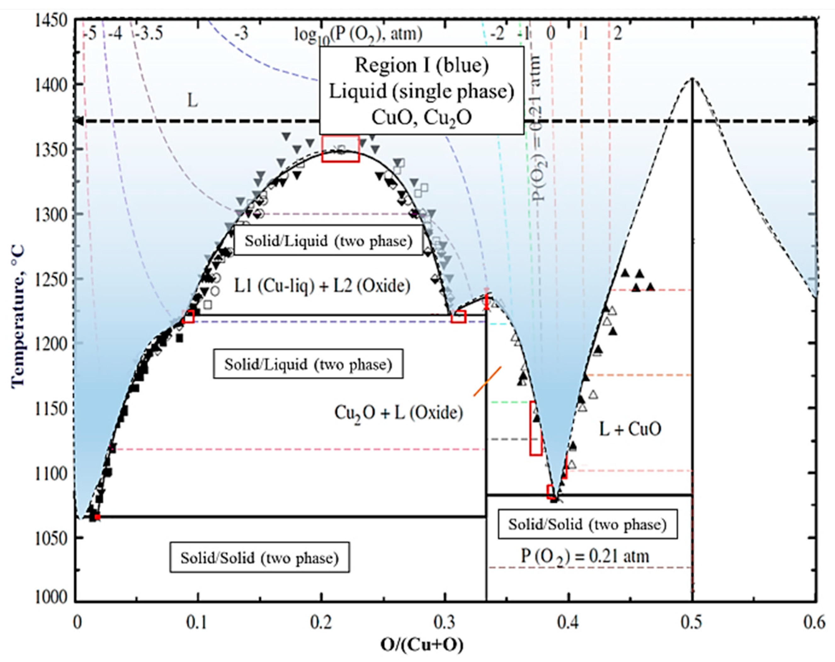
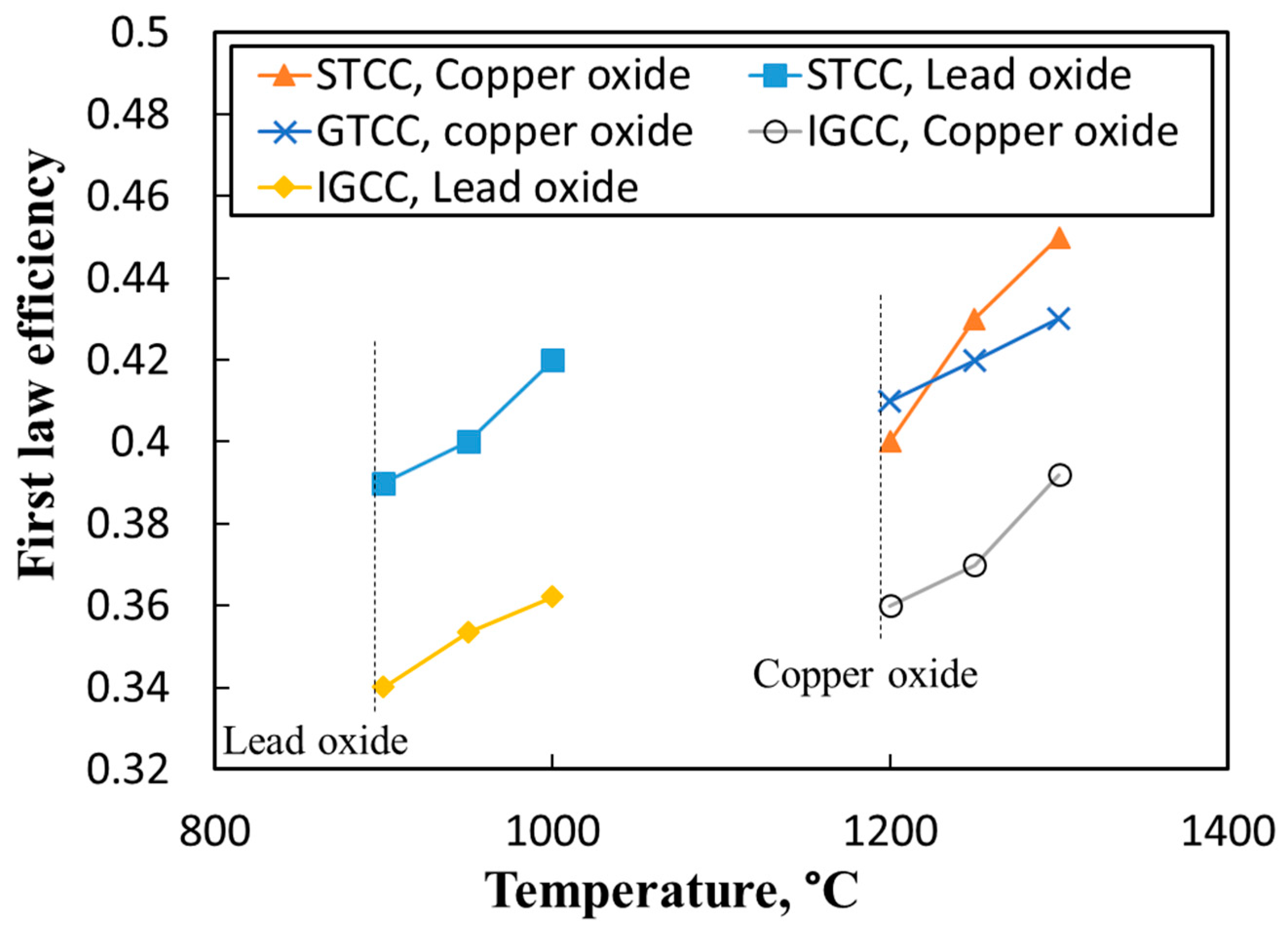
3.1. Operating Temperature in the Air Reactor

The FLE of the IGCC, STCC and GTCC power blocks as a function of temperature is depicted in Figure 7. Lead oxide can only be used for integrated gasification combined cycle (IGCC) at a temperature range between 900 and 1000 °C and steam turbine combined cycle (STCC) at a temperature between 1200 and 1300 °C. The melting temperature of metal oxides determined the operating temperature of the power cycles. For lead oxide, the STCC power block showed a higher FLE in comparison with IGCC. For instance, at a operating temperature of 1000 °C, the FLE was 0.42 for the STCC, while it was only 0.37 for the IGCC. This was simply because the LCLG system prevents direct contact between air and fuel. As a result, nitrogen was removed from the syngas and the ratio of Cp/Cv of the exhausted gas due to the combustion of high-quality syngas (mainly CO2, H2O) was lower than that of the exhausted gases obtained from conventional gasifiers (CO2, H2, N2) (1.08 vs. 1.21). Overall, it can be stated that the LCLG process produced high-quality syngas, which was neither suitable for integrated gasification nor the combustion process.
For copper oxide, higher operating temperature was required in comparison with lead oxide. Hence, STCC and GTCC showed better energetic performance in comparison with IGCC. For copper oxide, the thermodynamically defined upper limit temperature was considerably higher than that of lead oxide (1300–1350 °C versus 900–1000 °C), therefore, higher Carnot efficiency was obtained from the power cycle connected to the LCLG working with copper oxide. As can be seen in Figure 7, at operating temperatures higher than 1250 °C, the FLE of STCC power block was higher than that of GTCC and IGCC. For instance, at 1300 °C, the FLE for STCC was 0.45, which was 7% higher than the efficiency obtained for GTCC at this temperature. The IGCC power block still represented the lowest FLE of 0.39 at 1300 °C. Temperature was found to have a strong influence on the efficiency of power cycles. Regardless of the type of working medium in the LCLG system, FLE of the power cycle linearly increased with temperature, meaning that the highest efficiency was obtained at the highest temperature, which in turn was the upper limit temperature of the power cycle.

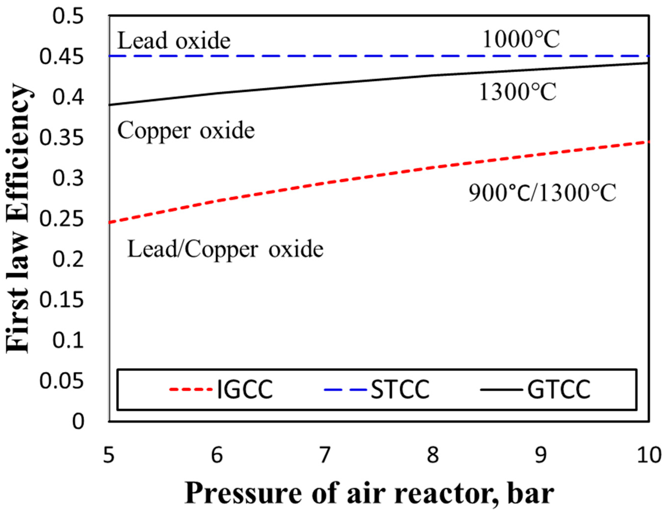
3.2. Operating Pressure in the Air Reactor

Pressure was another operating parameter in the LCLG process, which directly influenced the outlet lines connected to the power cycles. More importantly, pressurizing the reactors, (particularly the air reactor), hindered the solidification of liquid copper oxide, while increasing the exergy in the outlet of reactors.
The FLE of the system, as a function of the pressure of the reactor, has been depicted in Figure 8. For the STCC, pressurizing the air reactor had no impact on the efficiency of the power cycle, as the major quantity of work was obtained from the main gas turbine (FR-GT) and the air reactor outlet was used in a steam generation unit. However, pressurizing the air reactor may have facilitated the operating of the air reactor when the lead oxide was used to handle the process exactly in the operating region shown in Figure 5, and to maintain the plausible condition for better phase contact, while preventing solidification.
For the GTCC power cycle, increasing the pressure of the air reactor provided higher exergy in the main gas turbine (FR-GT), which generated more work. Based on the phase diagram, we considered the minimum and maximum pressure limitations to be 5 and 10 bar, respectively. Notably, at temperatures such as 1300 °C, operation of the pressurized reactor was technically challenging and needed specific design and considerations, which hinged on the type of material used for the fabrication of the reactor, its design and operating mode (batch, semi-batch or continuous operation). Refractory materials offered a wide range of characteristics such as high-temperature resistance, high-pressure tolerance, reduced erosion and corrosion. As shown in Figure 8, the work produced in the GTCC power cycle increased as the pressure of the air reactor increased. For instance, at a pressure of 5 bar, the FLE was calculated to be 0.36, which increased to 0.45 at a pressure of about 10 bar. One advantage of the STCC power cycle was that this power cycle offers identical performance without any requirements for pressurizing the air reactor, allowing operating costs to be reduced. For the IGCC power cycle, pressure had a slight impact on the FLE of the power cycle. By increasing the temperature, the FLE increased, however, overall efficiency was considerably lower than that of GTCC and STCC due to the absence of nitrogen in exhausted gases that decreased the Cp/Cv ratio and amount of work delivered by the turbine due to the expansion of exhausted gases.
Notably, the flow rate of air had two major effects on the performance of the air reactor. It not only affected the composition of the vitiated air from the air reactor, but it also affected the enthalpy and exergy carried by the vitiated gas from the air reactor. Likewise, it controlled the rate of regeneration of the oxygen carrier in the air reactor. The detailed assessment of the air reactor had already been done in previous works and was beyond the scope of the present investigation [9,10].

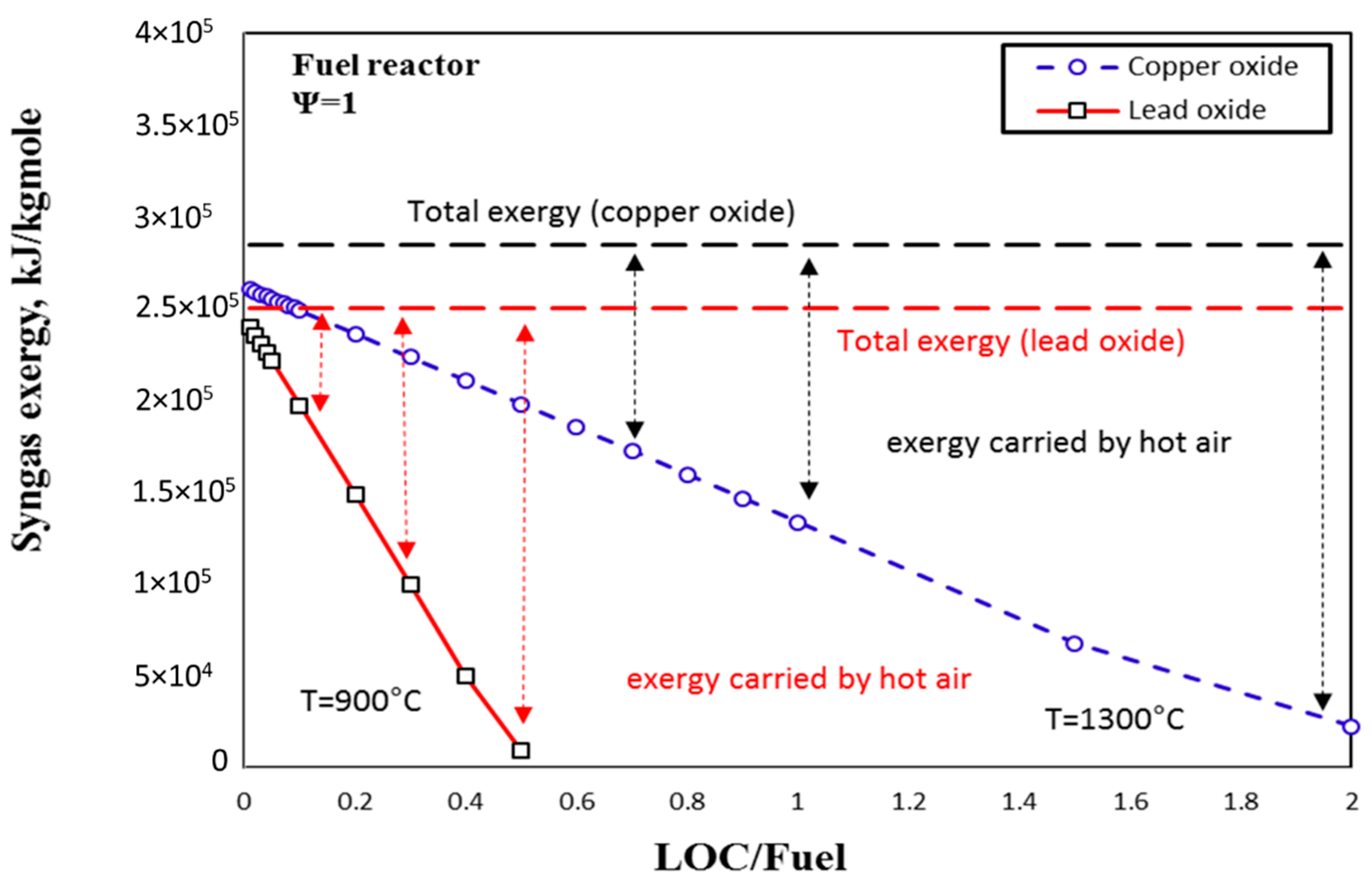
3.3. Exergy Analysis of LCLG

Figure 9 shows the dependence of syngas exergy on the parameter φ for copper and lead oxides. As can be seen, for copper oxide, as operating temperature was high, the LCLG system presented higher total exergy. At lower values of φ , syngas carried the larger portion of exergy. As φ increased, the LCLG system behaviour changed to the chemical looping combustion, meaning that the outlet of the reactor mainly comprised of carbon dioxide and water, therefore, more exergy was carried by the hot air from the air reactor. This behaviour can be seen for both lead and copper oxide, however, for a given φ , syngas produced by the LCLG working with copper oxide had a higher syngas quality and subsequently carried more exergy. This was the significant impact of this system—the LCLG system not only produced sufficient work when compared to other available technologies but also provided a clean line of syngas, which carried a significant amount of exergy.
For a better understanding, the variation of exergy efficiency for different values of φ is shown in Figure 10, which presents the portion of exergy carried by syngas and hot air. Figure 10 presents the variation of exergy efficiency with φ for the LCLG system working with liquid copper oxide as the LOC at a temperature of 1300 °C. As can be seen, for small values of φ , exergy efficiency remained constant but at higher values (0.68 to 0.65), with increasing φ , syngas lost its quality and exergy at the same time. Interestingly, at φ = 0.5, both syngas and hot air carried the same amount of exergy, which can be used for further application. Accordingly, the LCLG offered the exergy management and flexibility to manipulate the quantity of exergy required for any applications.
Figure 11 shows the exergy analysis for the LCLG system working with liquid lead oxide. As can be seen at φ = 0.1, the portion of exergy for syngas and hot gases was similar and at lower values of φ , exergy efficiency varied from 0.61 to 0.58 for φ = 0.01 to φ = 0.05, however, exergy efficiency of syngas for φ higher than 0.5 was less than 0.05, meaning that the significant amount of exergy was carried by the hot air. A rough comparison between the exergy efficiency of syngas for copper oxide and lead oxides revealed that syngas produced by the LCLG working with copper oxide had higher exergy efficiency in comparison with the one produced in the LCLG working with lead oxide (0.68 vs. 0.61). However, to provide this amount of exergy with copper oxide, the LCLG needed to work at temperatures and pressures as high as 1300 °C and 5 bar, respectively, which is very challenging.

3.4. Comparison of the Proposed Power Cycles and Those Available in the Literature

To compare the energetic performance of the proposed power cycles with those available in the literature, power cycles working at similar temperatures and pressure to that of the LCLG were selected from the literature. Figure 12 comparatively shows the FLE of the IGCC power cycle in comparison with the literature. The temperature was 1300 °C and the copper oxide was used in the LCLG system. As can be seen, FLE of the IGCC power cycle integrated with the LCLG stood amongst the state of the art IGCC power cycles. For instance, efficiency of the IGCC power cycle was only 3% lower than that for the power cycle proposed by Alvaro et al. [29], 6% lower than that reported by Milan University [30] and was the same as the one reported by National Energy Technology Laboratory (NETL) [31]. However, the LCLG system offered a clean stream of high-quality syngas, which carried a significant amount of exergy that can be used for further applications such as Fischer–Tropsch, hydrogen production or in a combustion process. This advantage kept the proposed IGCC-LCLG amongst the state-of-the-art power cycles.
Figure 13 shows a comparison between the FLE of the proposed GTCC power cycle with those publicaly available in the literature at the same operating conditions. The operating temperature was 1300 °C and the LCLG system worked with copper oxide. As can be seen, the proposed GTCC power cycle wa the second efficient power cycle with the efficiency of 43.8% after the power cycle proposed by Spelling et al. [35] with the efficiency of 55%, and represented the same FLE equivalent to that of reported by Taimoor et al. [36] (43.8%), for its power cycle. The efficiency was higher than some works performed by Xuan et al. [37] (35%), and Rio et al. [38] (40%). More importantly, the GTCC power cycle offered a clean, low-temperature stream of syngas, which can be directly used by Fischer–Tropsch, or any fuel cells. This feature implied that the proposed power cycle was more efficient in comparison with other power cycles considering the post-application of the syngas.
Figure 14 shows the comparison between the FLE of the proposed STCC power cycle and those available in the literature. The operating temperature was 900 °C and the LCLG system worked with lead oxide. As observed in this figure, the FLE for the proposed power cycle stands second (efficiency = 45%) after Ozgener et al. [39], which achieved an FLE equivalent to 57%. The efficiency was equivalent to the power cycle proposed by Jaffar et al. [40], which was around 45% and was higher than the rest of the works. The LCLG still offered a clean line of syngas, which can be used for post-applications. The rate of carbon dioxide can be as low as 0.2% depending on the quality of the syngas and rate of circulation of LOC in the system.
It is worth mentioning that despite the similar efficiency of the proposed combined cycles, they can coproduce synthetic gas as well, which in turn promotes the chemical exergy and chemical efficiency of the power plants. Hence, the main advantage of the proposed power plants is to produce a high-quality synthetic gas at lower temperatures (e.g., 800 °C) in comparison with the state of the art GTCC power plants (e.g., 1200 °C) with higher chemical exergetic and energetic efficiency.

4. Conclusions

Exergy and energy performance of the LCLG integrated with three different configurations of power block were carried out. The key conclusions of this work are:
(1)
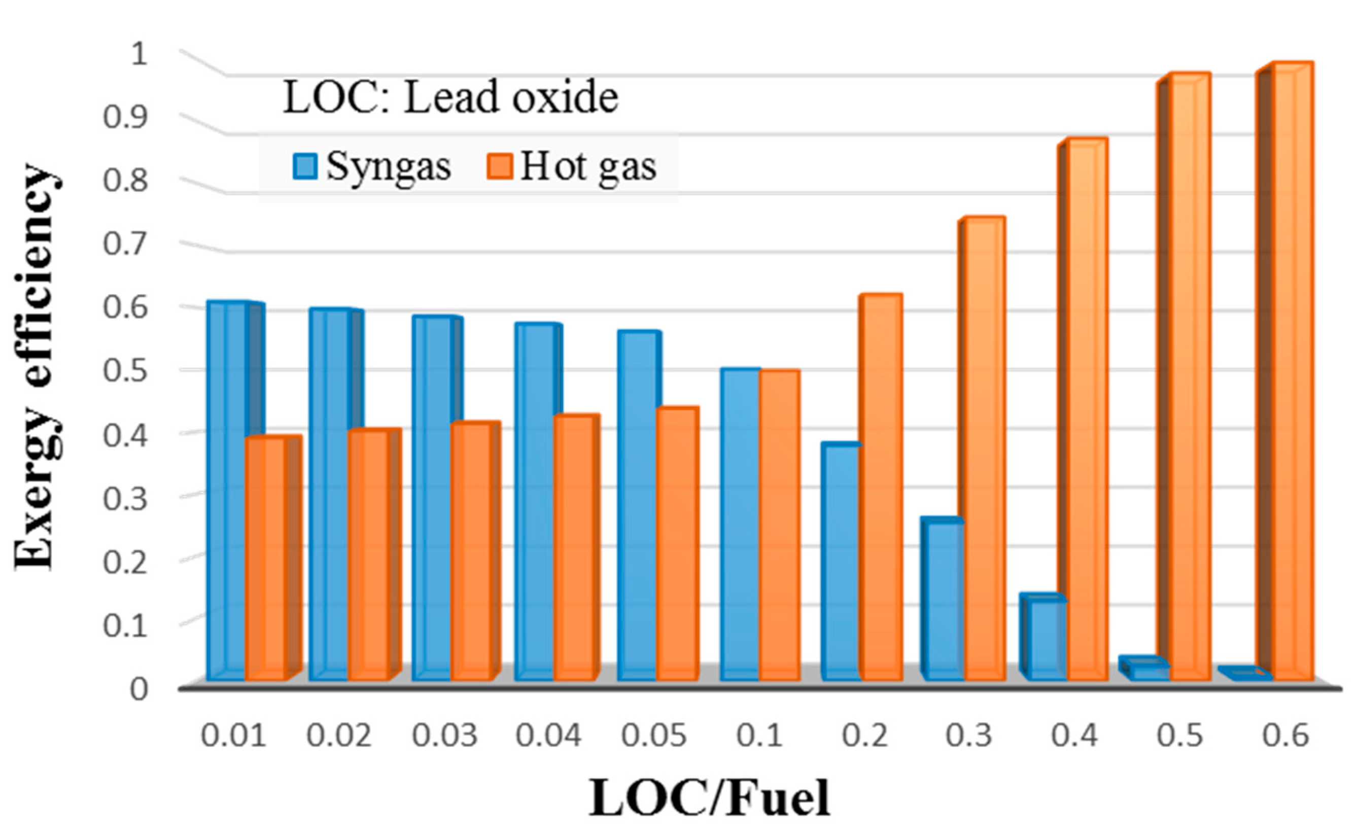
Exergy analysis of the LCLG system working with molten lead oxide showed that ϕ had a strong influence on the quality and level of exergy carried by syngas. For 0.01 < ϕ < 0.05 , more exergy was carried by the syngas produced, while for values ϕ > 0.05 , hot air carried the higher exergy as the quality of syngas reduced. This meant that the LCLG system working at ϕ > 0.05 could provide more work by power block, while ϕ < 0.05 syngas could provide more work in Fischer–Tropsch or other applications.
(2)
When copper oxide was used in LCLG, for 0.01 < ϕ < 0.5 , more exergy was carried by syngas, and at ϕ > 0.5 , the system was capable of producing more work by power block.
(3)
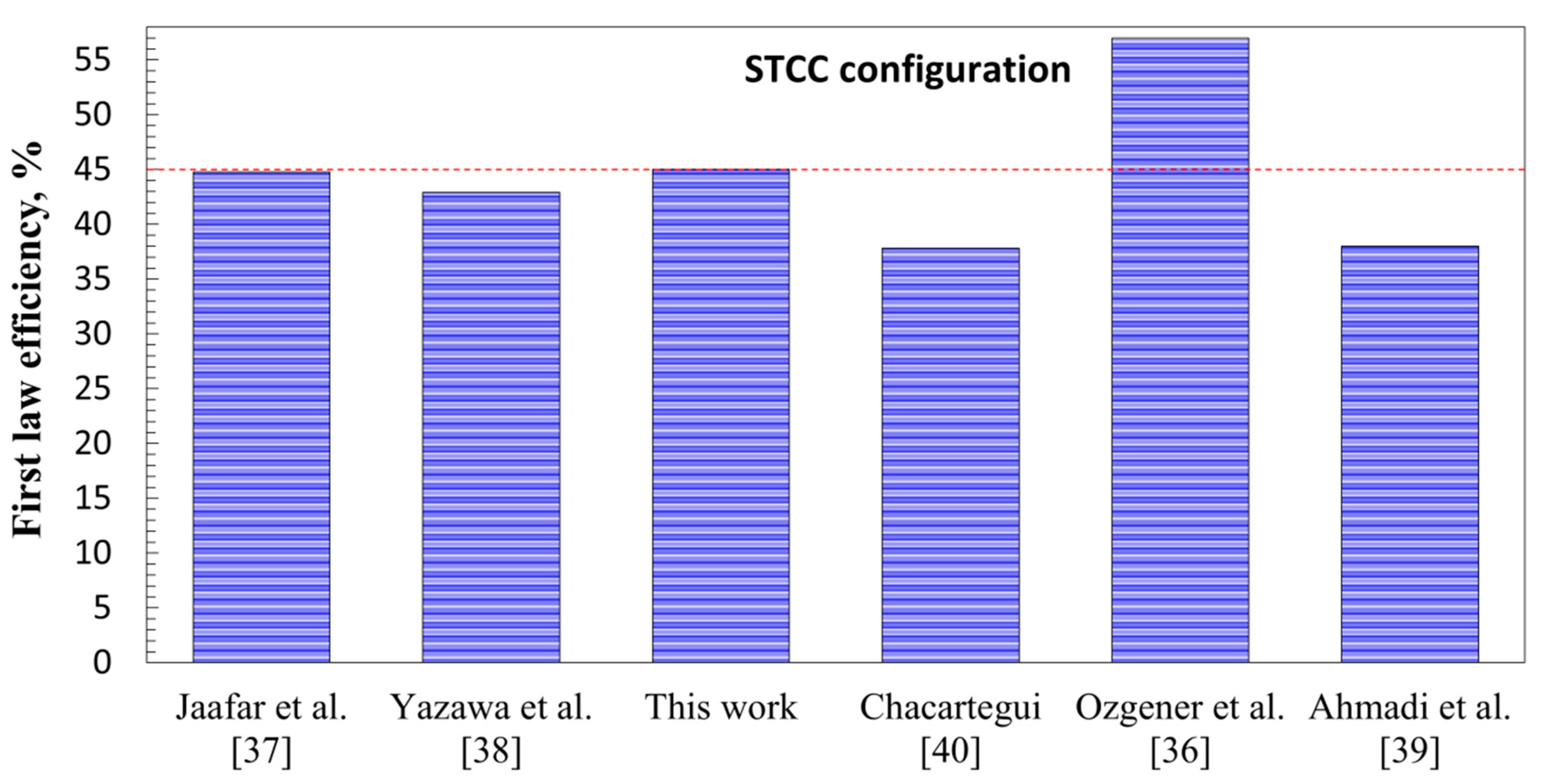
The STCC integrated with the LCLG system working with lead oxide showed that the first law and exergy efficiency for ϕ = 0.05 achieved values of 0.43 and 0.68, respectively. It provided a cold and clean stream of high-quality syngas, which can be used in a Fischer–Tropsch unit.
(4)
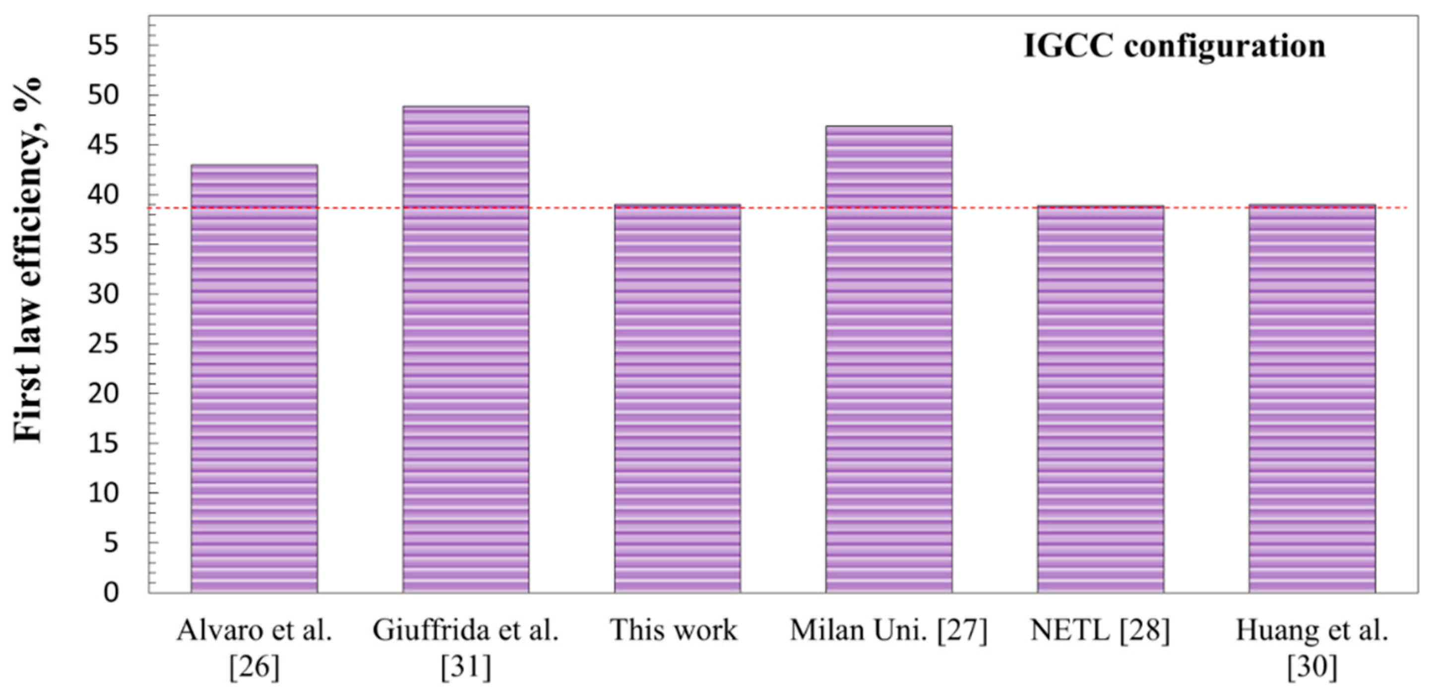
The IGCC integrated with the LCLG system working with both copper oxide and lead oxide showed lower efficiency in comparison with the STCC and GTCC power blocks. This is because in outlet syngas, nitrogen is omitted and the quality of syngas is high enough for other chemical applications rather than combustion or producing work.

Author Contributions

Conceptualization, M.M.S, M.R.S, M.G., A.S.L.; methodology, M.M.S., U.K.; formal analysis, M.M.S., R.M.; investigation, M.M.S., M.R.S.; writing—original draft preparation, M.M.S., M.G.; writing—review and editing, A.S.L., M.G., M.M.S., M.R.S., U.K., R.M.

Funding

This work is financially supported by the Deanship of Scientific Research at King Saud University through Research Group No. (RG-1439-70).

Acknowledgments

The authors acknowledge the University of Adelaide for providing experimental facilities. The authors also extend their appreciation to the Deanship of Scientific Research at King Saud University for funding this work through Research Group No. (RG-1439-70).

Conflicts of Interest

The authors declare no conflicts of interest.

Nomenclature

ExExergy, kJ/kmol
WWork, kJ
n ˙ Molar flow rate, kmol/hr
Greek letters
φ Liquid oxygen carrier to fuel ratio or steam to fuel ratio
Δ Difference
η First law efficiency, %
χ Exergy efficiency, %
Abbreviations
ARAir Reactor
Eq.Equation
FRFuel Reactor
GTGas Turbine
GTCCGas Turbine Combined Cycle
STSteam Turbine
STCCSteam Turbine Combined Cycle
LHVLower Heating Value, MJ/kg
LOCLiquid Oxygen Carrier

References

  1. Ge, H.; Zhang, H.; Guo, W.; Song, T.; Shen, L. System simulation and experimental verification: Biomass-based integrated gasification combined cycle (BIGCC) coupling with chemical looping gasification (CLG) for power generation. Fuel 2019, 241, 118–128. [Google Scholar] [CrossRef]
  2. Hu, J.; Li, C.; Guo, Q.; Dang, J.; Zhang, Q.; Lee, D.-J.; Yang, Y. Syngas production by chemical-looping gasification of wheat straw with Fe-based oxygen carrier. Bioresour. Technol. 2018, 263, 273–279. [Google Scholar] [CrossRef]
  3. Li, F.; Kim, H.R.; Sridhar, D.; Wang, F.; Zeng, L.; Chen, J.; Fan, L.-S. Syngas chemical looping gasification process: Oxygen carrier particle selection and performance. Energy Fuels 2009, 23, 4182–4189. [Google Scholar] [CrossRef]
  4. Dadsetani, R.; Sheikhzadeh, G.A.; Safaei, M.R.; Alnaqi, A.A.; Amiriyoon, A. Exergoeconomic optimization of liquefying cycle for noble gas argon. Heat Mass Transf. 2019, 55, 1995–2007. [Google Scholar] [CrossRef]
  5. Fan, L.; Li, F.; Ramkumar, S. Utilization of chemical looping strategy in coal gasification processes. Particuology 2008, 6, 131–142. [Google Scholar] [CrossRef]
  6. Scott, S.; Dennis, J.; Hayhurst, A.; Brown, T. In situ gasification of a solid fuel and CO2 separation using chemical looping. AIChE J. 2006, 52, 3325–3328. [Google Scholar] [CrossRef]
  7. Safaiy, M.; Maghmoumi, Y.; Karimipour, A. Economic evaluation of utilization of electro-feed water pump and turbo-feed water pump and compare them in a 12.5-megawatts steam unit thermal cycle and provide the optimum solution. AIP Conf. Proc. 2012, 1440, 550–555. [Google Scholar]
  8. Adanez, J.; Abad, A.; Garcia-Labiano, F.; Gayan, P.; Luis, F. Progress in chemical-looping combustion and reforming technologies. Progress Energy Combust. Sci. 2012, 38, 215–282. [Google Scholar] [CrossRef]
  9. Sarafraz, M.M.; Jafarian, M.; Arjomandi, M.; Nathan, G.J. Potential use of liquid metal oxides for chemical looping gasification: A thermodynamic assessment. Appl. Energy 2017, 195, 702–712. [Google Scholar] [CrossRef] [Green Version]
  10. Sarafraz, M.M.; Jafarian, M.; Arjomandi, M.; Nathan, G.J. The relative performance of alternative oxygen carriers for liquid chemical looping combustion and gasification. Int. J. Hydrogen Energy 2017, 42, 16396–16407. [Google Scholar] [CrossRef]
  11. Cormos, A.-M.; Cormos, C.-C. Investigation of hydrogen and power co-generation based on direct coal chemical looping systems. Int. J. Hydrogen Energy 2014, 39, 2067–2077. [Google Scholar] [CrossRef]
  12. Cormos, C.-C. Evaluation of syngas-based chemical looping applications for hydrogen and power co-generation with CCS. Int. J. Hydrogen Energy 2012, 37, 13371–13386. [Google Scholar] [CrossRef]
  13. Maurstad, O. An Overview of Coal Based Integrated Gasification Combined Cycle (IGCC. In Proceedings of Technology; MIT LFEE 2005-002 WP; Laboratory for Energy and the Environment, Massachusetts Institute of Technology: Cambridge, MA, USA, 2005. [Google Scholar]
  14. Ståhl, K.; Neergaard, M. IGCC power plant for biomass utilisation, Värnamo, Sweden. Biomass Bioenergy 1998, 15, 205–211. [Google Scholar] [CrossRef]
  15. Gasification, I. An Overview of Coal Based Integrated Gasification Combined Cycle (IGCC) Technology; Cambridge, MA, USA, 2005. Available online: citeseerx.ist.psu.edu/viewdoc/download?doi=10.1.1.208.5891&rep=rep1&type=pdf (accessed on 22 September 2019).
  16. Manente, G.; Lazzaretto, A. Innovative biomass to power conversion systems based on cascaded supercritical CO2 Brayton cycles. Biomass Bioenergy 2014, 69, 155–168. [Google Scholar] [CrossRef]
  17. Traverso, A.; Massardo, A.F.; Scarpellini, R. Externally fired micro-gas turbine: Modelling and experimental performance. Appl. Therm. Eng. 2006, 26, 1935–1941. [Google Scholar] [CrossRef]
  18. Bracht, M.; Alderliesten, P.; Kloster, R.; Pruschek, R.; Haupt, G.; Xue, E.; Ross, J.; Koukou, M.; Papayannakos, N. Water gas shift membrane reactor for CO2 control in IGCC systems: Techno-economic feasibility study. Energy Convers. Manag. 1997, 38, S159–S164. [Google Scholar] [CrossRef]
  19. Chiesa, P.; Kreutz, T.G.; Lozza, G.G. CO2 sequestration from IGCC power plants by means of metallic membranes. J. Eng. Gas Turbines Power 2007, 129, 123–134. [Google Scholar] [CrossRef]
  20. Holt, N.; Booras, G.; Todd, D. A summary of recent IGCC studies of CO2 capture for sequestration. In Proceedings of the Gasification Technologies Conference, San Francisco, CA, USA, 12–15 October 2003; pp. 12–15. [Google Scholar]
  21. Mukherjee, S.; Kumar, P.; Yang, A.; Fennell, P. Energy and exergy analysis of chemical looping combustion technology and comparison with pre-combustion and oxy-fuel combustion technologies for CO2 capture. J. Environ. Chem. Eng. 2015, 3, 2104–2114. [Google Scholar] [CrossRef]
  22. Jafarian, M.; Arjomandi, M.; Nathan, G.J. The energetic performance of a novel hybrid solar thermal & chemical looping combustion plant. Appl. Energy 2014, 132, 74–85. [Google Scholar] [CrossRef]
  23. Abbott, M.M.; Smith, J.M.; Van Ness, H.C. Introduction to Chemical Engineering Thermodynamics; McGraw-Hill: New York, NY, USA, 2001. [Google Scholar]
  24. Shishin, D.; Decterov, S.A. Critical assessment and thermodynamic modeling of the Cu–O and Cu–O–S systems. Calphad 2012, 38, 59–70. [Google Scholar] [CrossRef]
  25. Risold, D.; Nagata, J.-I.; Suzuki, R. Thermodynamic description of the Pb-O system. J. Phase Equilibria 1998, 19, 213–233. [Google Scholar] [CrossRef] [Green Version]
  26. Hong, H.; Han, T.; Jin, H. A low temperature solar thermochemical power plant with CO2 recovery using methanol-fueled chemical looping combustion. J. Sol. Energy Eng. 2010, 132, 031002. [Google Scholar] [CrossRef]
  27. Gou, C.; Cai, R.; Hong, H. A novel hybrid oxy-fuel power cycle utilizing solar thermal energy. Energy 2007, 32, 1707–1714. [Google Scholar] [CrossRef]
  28. Naqvi, R.; Wolf, J.; Bolland, O. Part-load analysis of a chemical looping combustion (CLC) combined cycle with CO2 capture. Energy 2007, 32, 360–370. [Google Scholar] [CrossRef]
  29. Álvaro, Á.J.; Paniagua, I.L.; Fernández, C.G.; Martín, J.R.; Carlier, R.N. Simulation of an integrated gasification combined cycle with chemical-looping combustion and carbon dioxide sequestration. Energy Convers. Manag. 2015, 104, 170–179. [Google Scholar]
  30. Anantharaman, R.; Bolland, O.; Booth, N.; van Dorst, E.; Ekstrom, C.; Sanchez Fernandes, E.; Franco, F.; Macchi, E.; Manzolini, G.; Nikolic, D. European best practice guidelines for assessment of CO2 capture technologies. SINTEF Trondheim Norway. 2007, 1. Available online: www.academia.edu/download/45301000/D_1.4.3_Euro_BP_Guid_for_Ass_CO2_Cap_Tech_280211.pdf (accessed on 22 September 2019).
  31. Coal, B.; Gas, N. Fossil Energy Power Plant Desk Reference; USA, 2007. Available online: citeseerx.ist.psu.edu/viewdoc/download?doi=10.1.1.222.3202&rep=rep1&type=pdf (accessed on 22 September 2019).
  32. Cormos, C.-C. Integrated assessment of IGCC power generation technology with carbon capture and storage (CCS). Energy 2012, 42, 434–445. [Google Scholar] [CrossRef]
  33. Huang, Y.; Rezvani, S.; McIlveen-Wright, D.; Minchener, A.; Hewitt, N. Techno-economic study of CO2 capture and storage in coal fired oxygen fed entrained flow IGCC power plants. Fuel Process. Technol. 2008, 89, 916–925. [Google Scholar] [CrossRef]
  34. Giuffrida, A.; Romano, M.C.; Lozza, G. Efficiency enhancement in IGCC power plants with air-blown gasification and hot gas clean-up. Energy 2013, 53, 221–229. [Google Scholar] [CrossRef]
  35. Aichmayer, L.; Spelling, J.; Laumert, B. Thermoeconomic Analysis of a Solar Dish Micro Gas-turbine Combined-cycle Power Plant. Energy Procedia 2015, 69, 1089–1099. [Google Scholar] [CrossRef] [Green Version]
  36. Taimoor, A.A.; Muhammad, A.; Saleem, W. Humidified exhaust recirculation for efficient combined cycle gas turbines. Energy 2016, 106, 356–366. [Google Scholar] [CrossRef]
  37. Aminov, Z.; Nakagoshi, N.; Xuan, T.D.; Higashi, O.; Alikulov, K. Evaluation of the energy efficiency of combined cycle gas turbine. Case study of Tashkent thermal power plant, Uzbekistan. Appl. Therm. Eng. 2016, 103, 501–509. [Google Scholar] [CrossRef]
  38. Del Rio, M.S.; Lucquiaud, M.; Gibbins, J. Maintaining the Power Output of an Existing Coal Plant with the Addition of CO2 Capture: Retrofits Options With Gas Turbine Combined Cycle Plants. Energy Procedia 2014, 63, 2530–2541. [Google Scholar]
  39. Ersayin, E.; Ozgener, L. Performance analysis of combined cycle power plants: A case study. Renew. Sustain. Energy Rev. 2015, 43, 832–842. [Google Scholar] [CrossRef]
  40. Ganjehkaviri, A.; Jaafar, M.M.; Hosseini, S. Optimization and the effect of steam turbine outlet quality on the output power of a combined cycle power plant. Energy Convers. Manag. 2015, 89, 231–243. [Google Scholar] [CrossRef]
  41. Yazawa, K.; Koh, Y.R.; Shakouri, A. Optimization of thermoelectric topping combined steam turbine cycles for energy economy. Appl. Energy 2013, 109, 1–9. [Google Scholar] [CrossRef]
  42. Ahmadi, G.R.; Toghraie, D. Energy and exergy analysis of Montazeri Steam Power Plant in Iran. Renew. Sustain. Energy Rev. 2016, 56, 454–463. [Google Scholar] [CrossRef]
  43. Chacartegui, R.; Sánchez, D.; De Escalona, J.M.; Jimenez-Espadafor, F.; Munoz, A.; Sánchez, T. SPHERA project: Assessing the use of syngas fuels in gas turbines and combined cycles from a global perspective. Fuel Process. Technol. 2012, 103, 134–145. [Google Scholar] [CrossRef]
Figure 1. Configuration of the proposed power block to be integrated with a liquid chemical looping gasification (LCLG) system (integrated gasification combined cycle—IGCC).
Processes 07 00763 g001
Figure 2. Configuration of the proposed power block to be integrated into an LCLG system (gas turbine combined cycle—GTCC), which can operate with molten copper oxide only.
Processes 07 00763 g002
Figure 3. Configuration of the proposed power block to be integrated into an LCLG system (steam turbine combined cycle—STCC).
Processes 07 00763 g003
Figure 4. Phase diagram of molten copper oxide reproduced with permission from [24].
Processes 07 00763 g004
Figure 5. Thermodynamic phase diagram obtained for lead and oxygen reproduced with permission from [25].
Processes 07 00763 g005
Figure 6. A schematic of the LCLG system connected to the power block. The liquid oxygen carrier (LOC) is circulated between reactors and the quality and exergy of syngas are controlled by the rate of circulation controls.
Processes 07 00763 g006
Figure 7. Dependence of first law efficiency (FLE) and produced work by steam turbines on the temperature of the air reactor for the LCLG-IGCC power block.
Processes 07 00763 g007
Figure 8. Dependence of FLE on the pressure of the air reactor.
Processes 07 00763 g008
Figure 9. Dependence of exergy carried by syngas and hot gas on the LOC/fuel ratio.
Processes 07 00763 g009
Figure 10. Exergy efficiency for the LCLG working with liquid copper oxide.
Processes 07 00763 g010
Figure 11. Exergy efficiency for LCLG working with liquid lead oxide.
Processes 07 00763 g011
Figure 12. A comparison between the FLE of the IGCC prepared in this work and those publically available [32,33,34].
Processes 07 00763 g012
Figure 13. A rough comparison between FLE obtained for the proposed GTCC and the values reported for other power blocks.
Processes 07 00763 g013
Figure 14. A rough comparison between FLE of the STCC assessed in this work and those reported in the literature [41,42,43].
Processes 07 00763 g014
Table 1. Assumptions and reference conditions used in the simulation.
Operating ConditionRangeSource
Gasifier
Operating pressure (for lead oxide)
Operating pressure (for copper oxide)
1–10 bar
1–10 bar
-
Operating temperature (for lead oxide)
Operating temperature (for copper oxide)
900–1000 °C
1100–1300 °C
-
LOC to fuel ratio (for lead oxide)0.01–0.5-
LOC to fuel ratio (for copper oxide)0.01–2-
Air reactor
Pressure (for lead oxide)
Pressure (for copper oxide)
1 bar
1 bar
-
Temperature (for lead oxide)
Temperature (for copper oxide)
900 °C
1300 °C
-
Power cycles
Gas turbine’s isentropic efficiency0.91[22,26]
Efficiency of the heat exchangers0.75-
Steam turbine’s isentropic efficiency0.9[27]
Pump’s efficiency0.75[22,28]
Gas turbine’s mechanical efficiency0.99[22]
Steam turbine’s mechanical efficiency0.99[22]
Table 2. Specification and characteristics of the IGCC, GTCC and STCC.
No.IGCC (Copper and Lead Oxide)GTCC (Only Copper Oxide)STCC (Copper and Lead Oxide)
TP Q ˙ TP Q ˙ TP Q ˙
11300 °C (Cu)
1000 °C (Pb)
10 bar
10 bar
1000 tonnes/hr (Cu)
1000 tonnes/hr (Pb)
1300 °C10 bar1000 tonnes/hr1300 °C (Cu)
1000 °C (Pb)
1 bar1000 tonnes/hr
21300 °C (Cu)
1000 °C (Pb)
10 bar
10 bar
998 tonnes/hr (Cu) and (Pb)1300 °C1 bar1000 tonnes/hr1300 °C (Cu)
1000 °C (Pb)
1 bar1000 tonnes/hr
31250 °C10 bar81,290 kmol/hr10841 bar34,541.2 kmol/hr35 °C1 bar52,158.7 kmol/hr
41300 °C (Cu)
1000 °C (Pb)
10 bar495 tonnes/hr (Cu)
422 tonnes/hr (Pb)
1300 °C1 bar1000 tonnes/hr166 °C1 bar24,590.2 kmol/hr
542 °C1 bar495 tonnes/hr (Cu)
422 tonnes/hr (Pb)
159 °C5 bar34,541.2 kmol/hr66 °C1 bar16,375 kmol/hr
6610 °C60 bar30,017 kmol/hr600 °C60 bar20,108 kmol/hr600 °C60 bar16,375 kmol/hr
7158 °C1 bar30,017 kmol/hr164 °C1 bar29,586 kmol/hr163 °C1 bar16375 kmol/hr
8160 °C1 bar81,290 kmol/hr58 °C1 bar29,586 kmol/hr54 °C1 bar16,375 kmol/hr
938 °C1 bar30,017 kmol/hr58 °C60 bar20,108 kmol/hr66 °C60 bar10,500 kmol/hr
1043 °C60 bar30,017 kmol/hr---1300 °C (Cu)
1000 °C (Pb)
1 bar500 tonnes/hr

