Overall Adaptive Controller Design of PMSG Under Whole Wind Speed Range: A Perturbation Compensation Based Approach


Abstract
1. Introduction
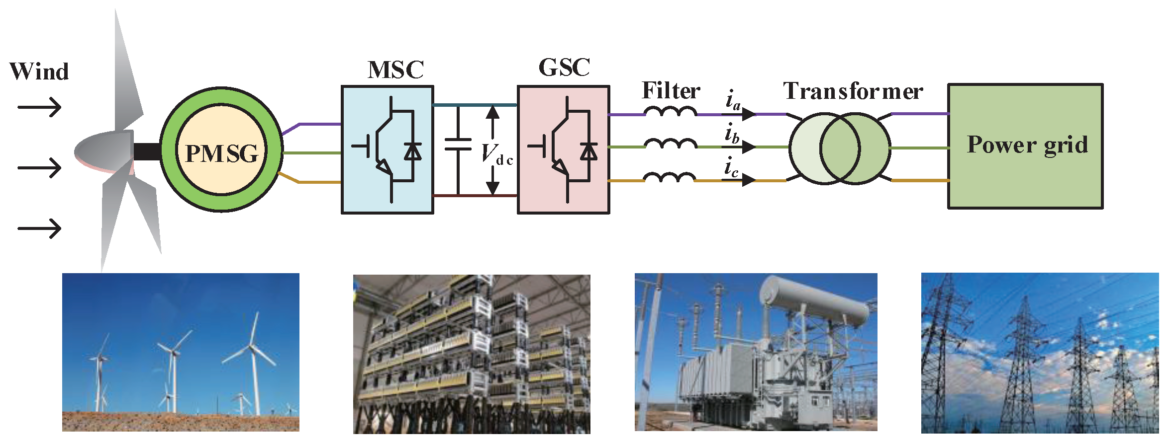
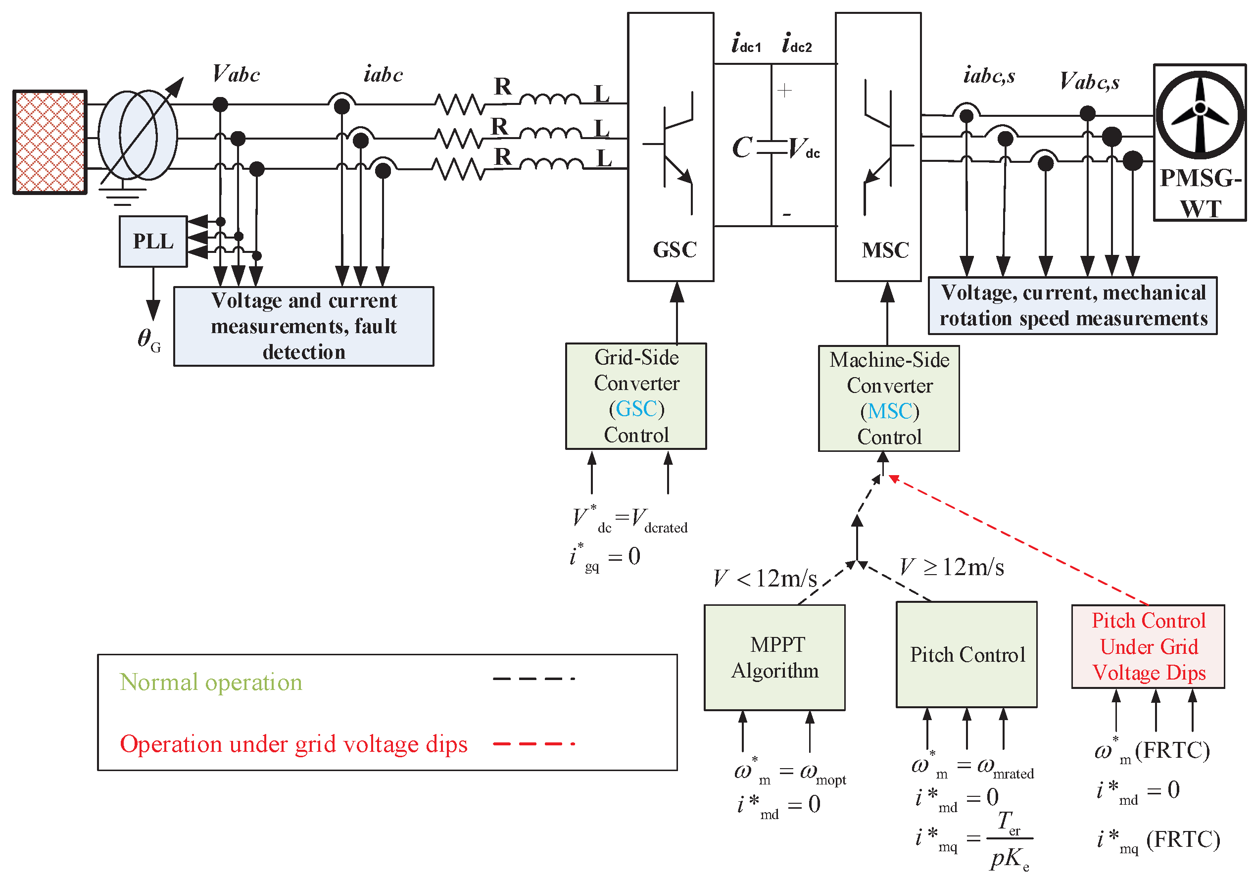
2. System Model
2.1. Model of Machine Side
2.2. Model of Grid Side
3. Adaptive Overall Control Approach of the WECS
3.1. Adaptive Pitch Control
3.1.1. Design for Proposed Strategy
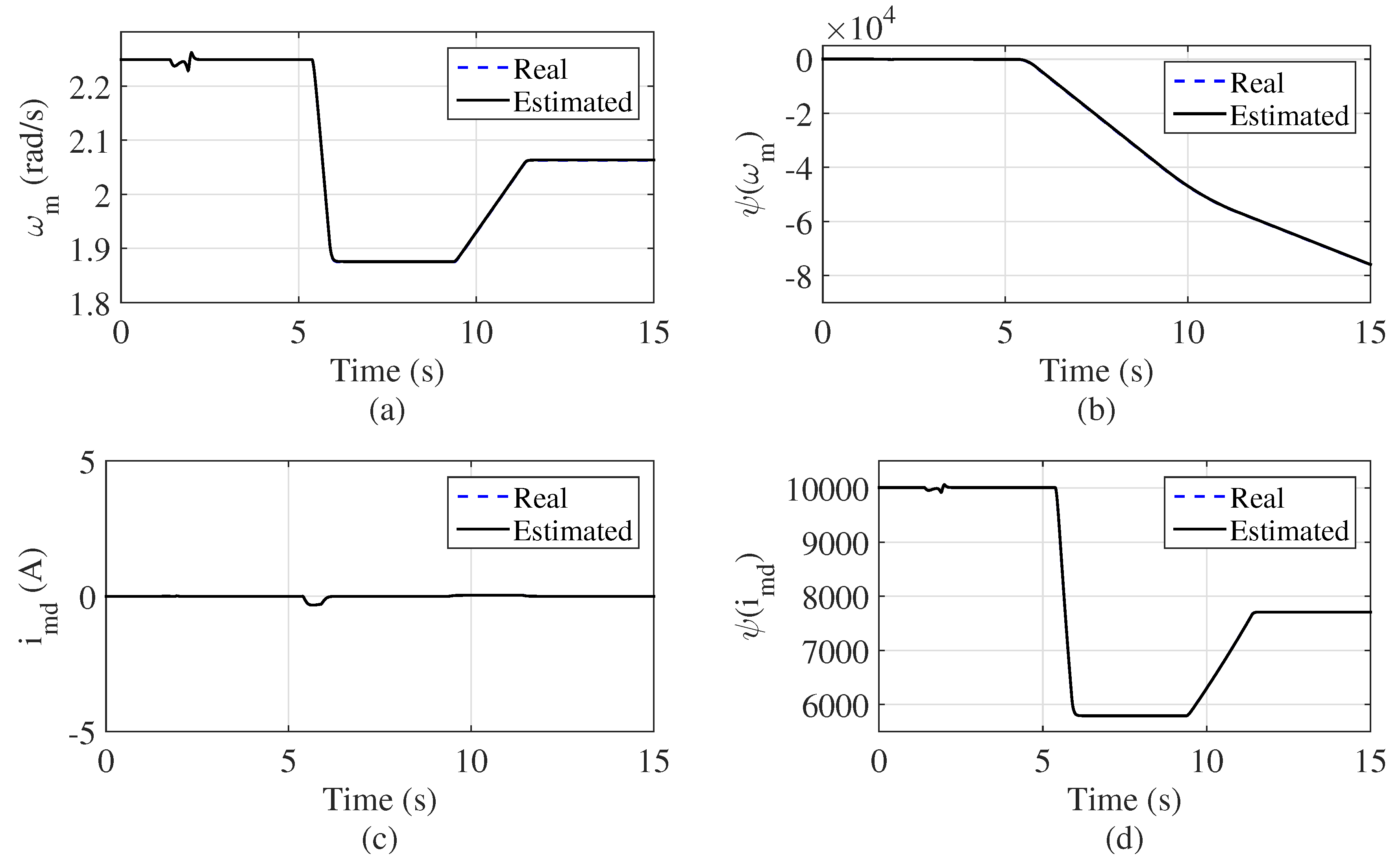
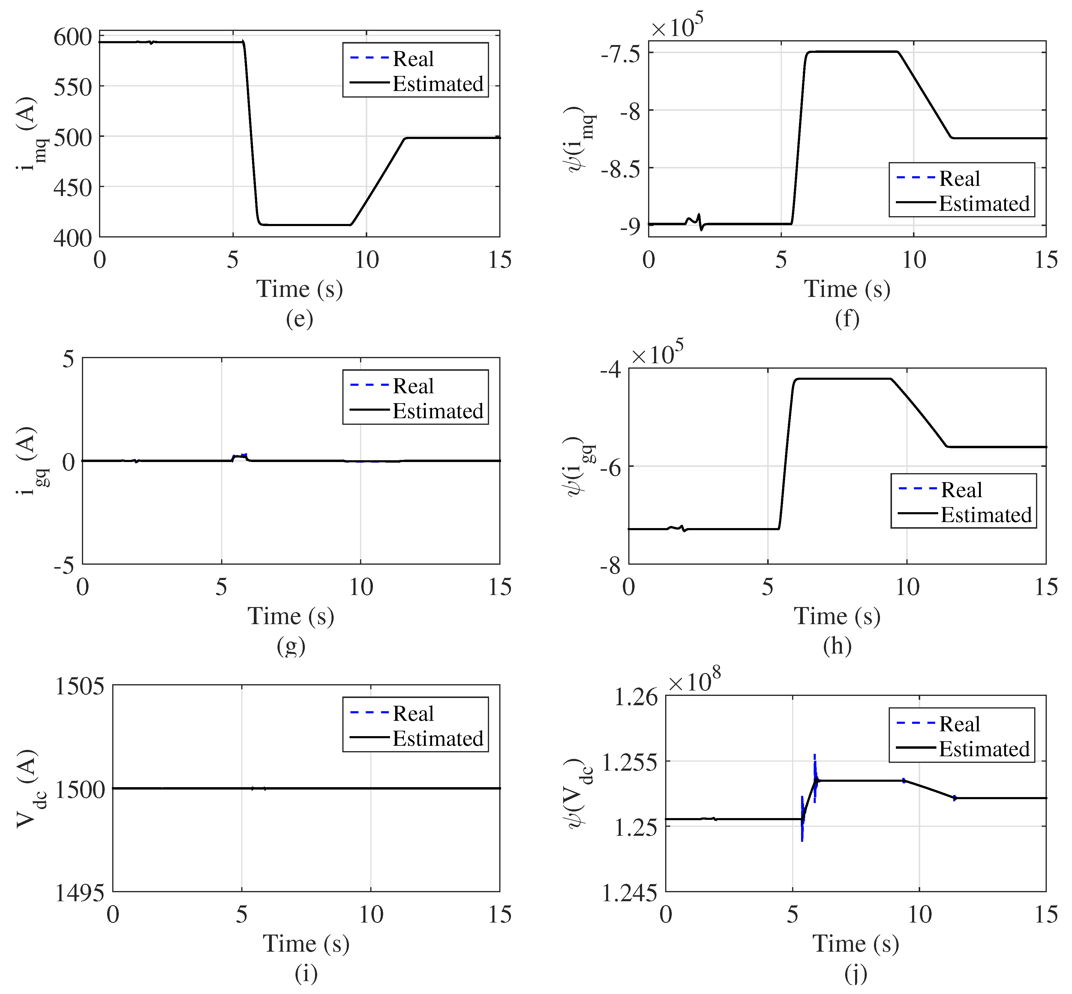
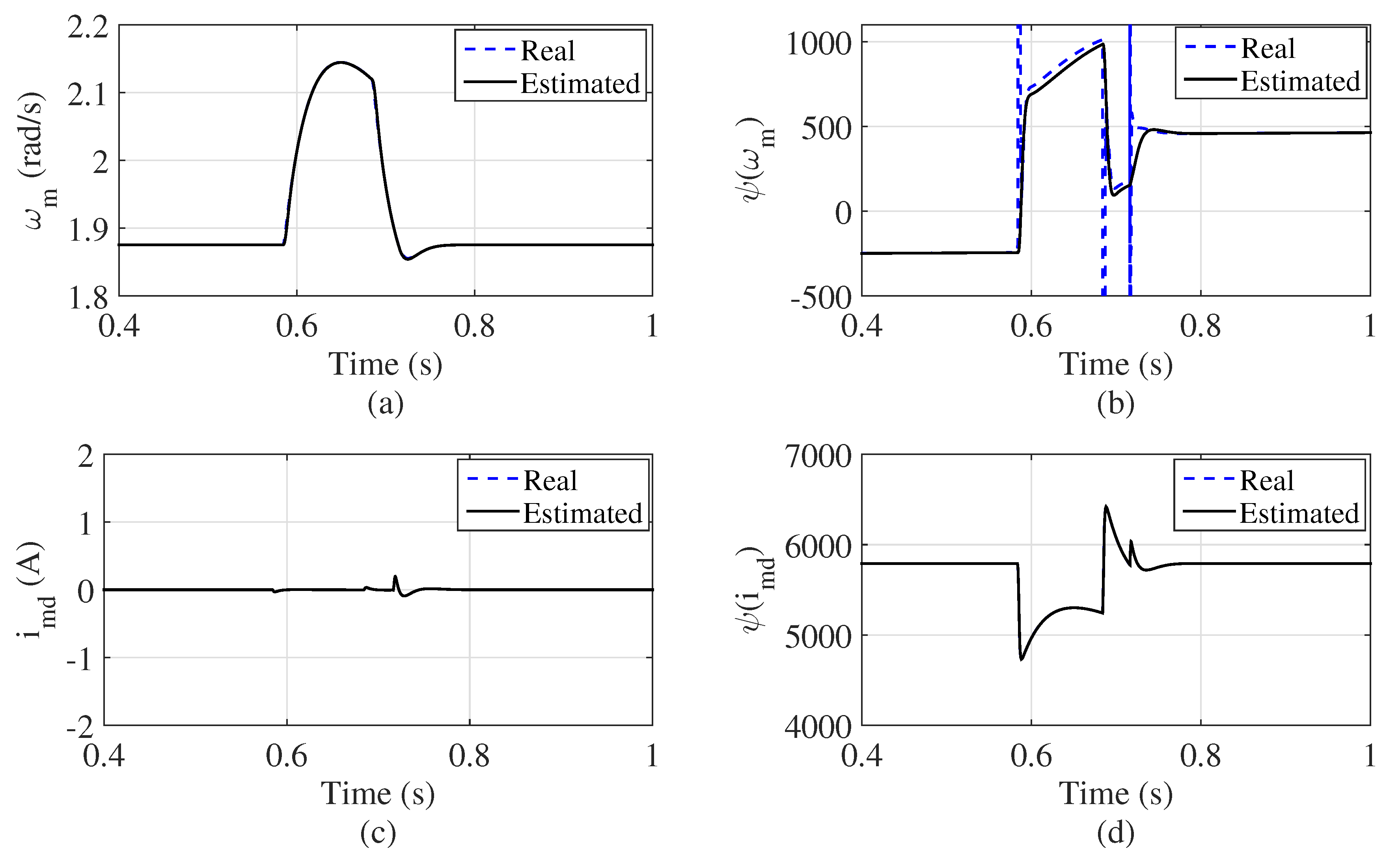
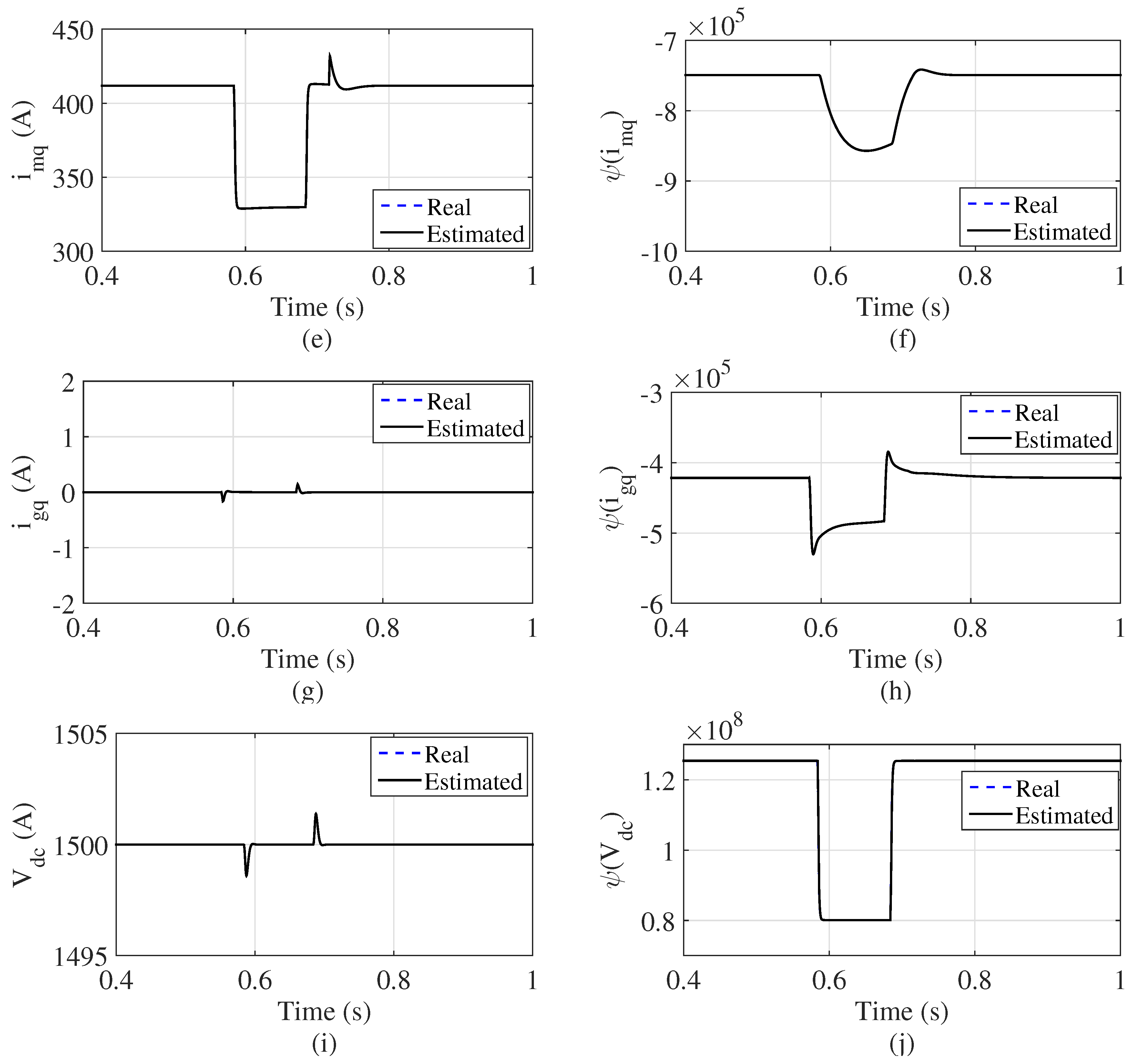
3.1.2. States and Perturbation Observer
- A.1.
- is chosen to meet: , where is a positive constant.
- A.2.
- The function and are locally Lipschitz in their arguments in the domain of interest and are globally bounded in x:where and are positive constants. Besides, and . Assumption can assure that the origin is an equilibrium point in the open-loop system.
3.1.3. Adaptive Control for PMSG-WT
3.2. Normal Operation
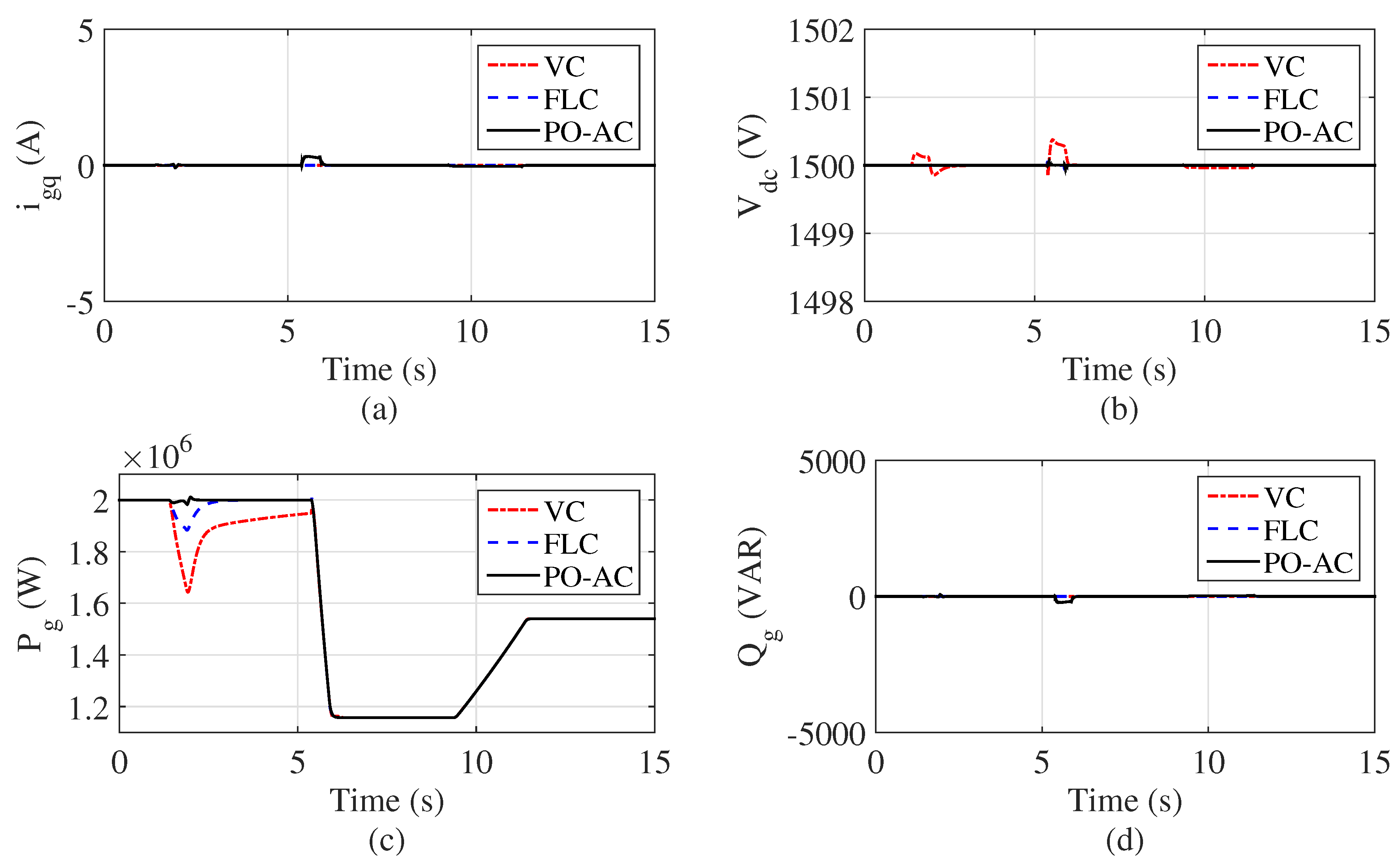
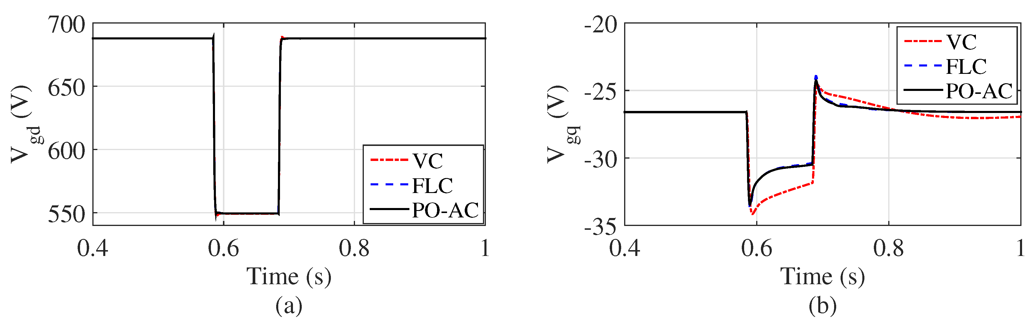
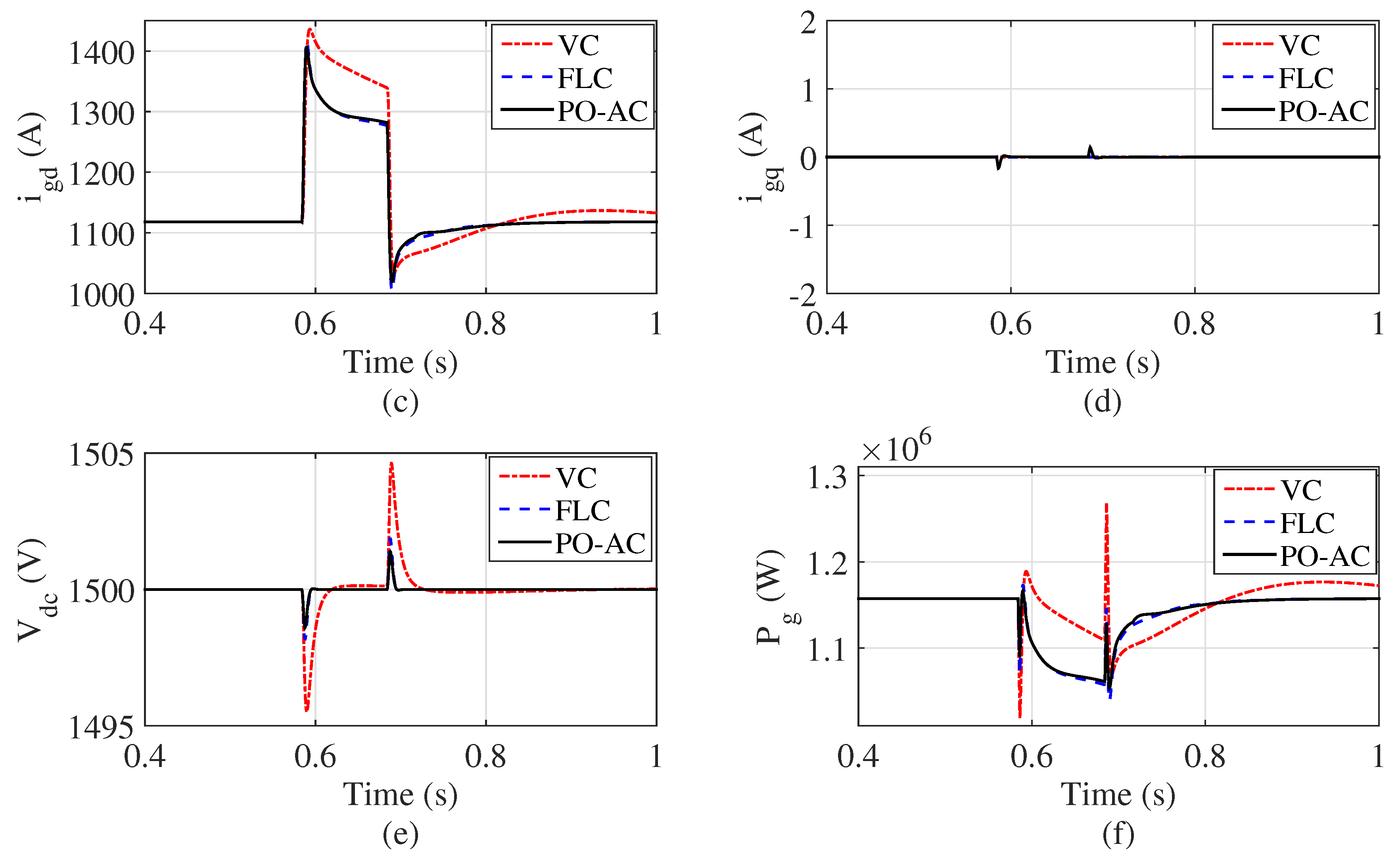
3.3. Operation Under Grid Voltage Dips
4. Simulation Results
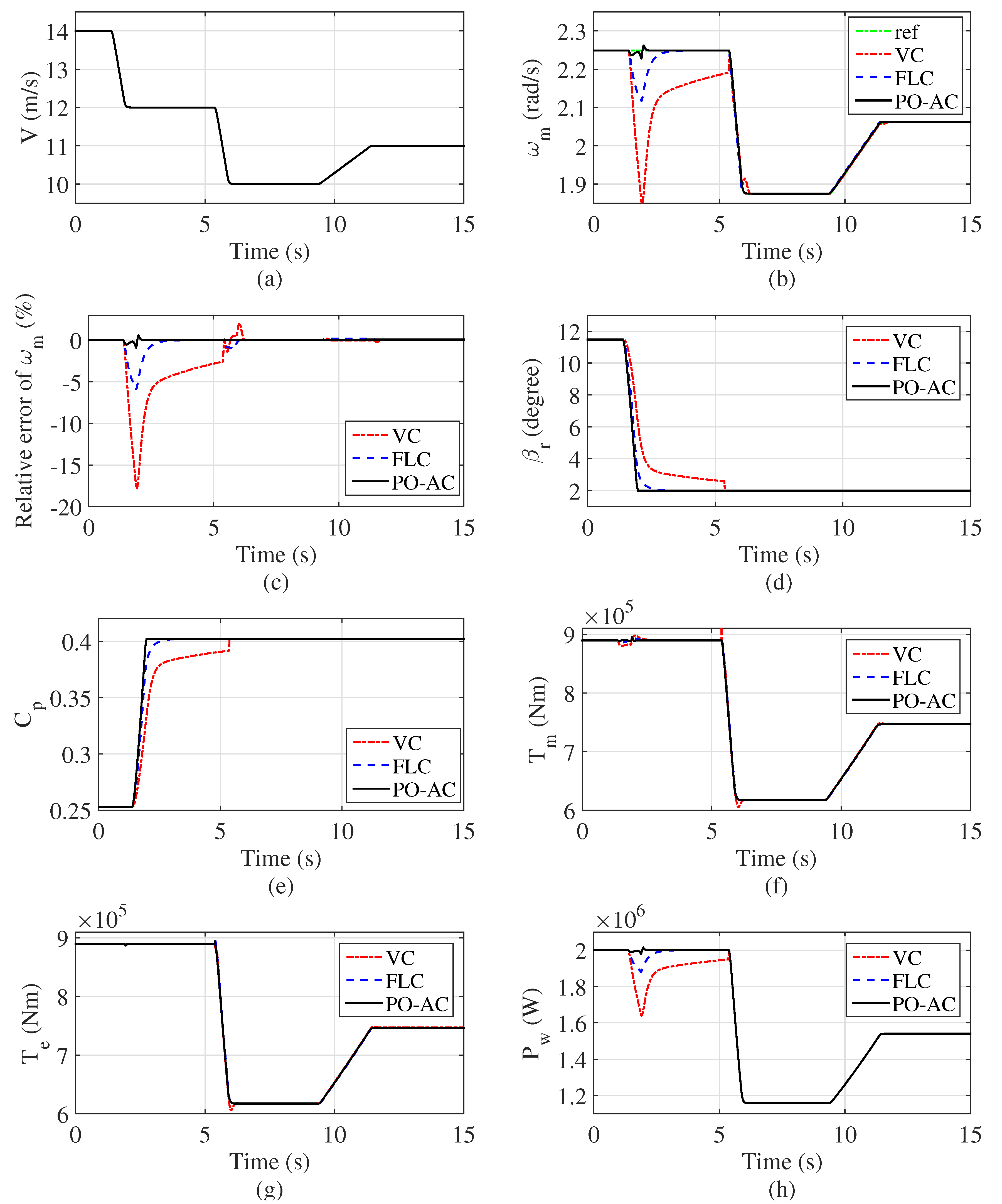
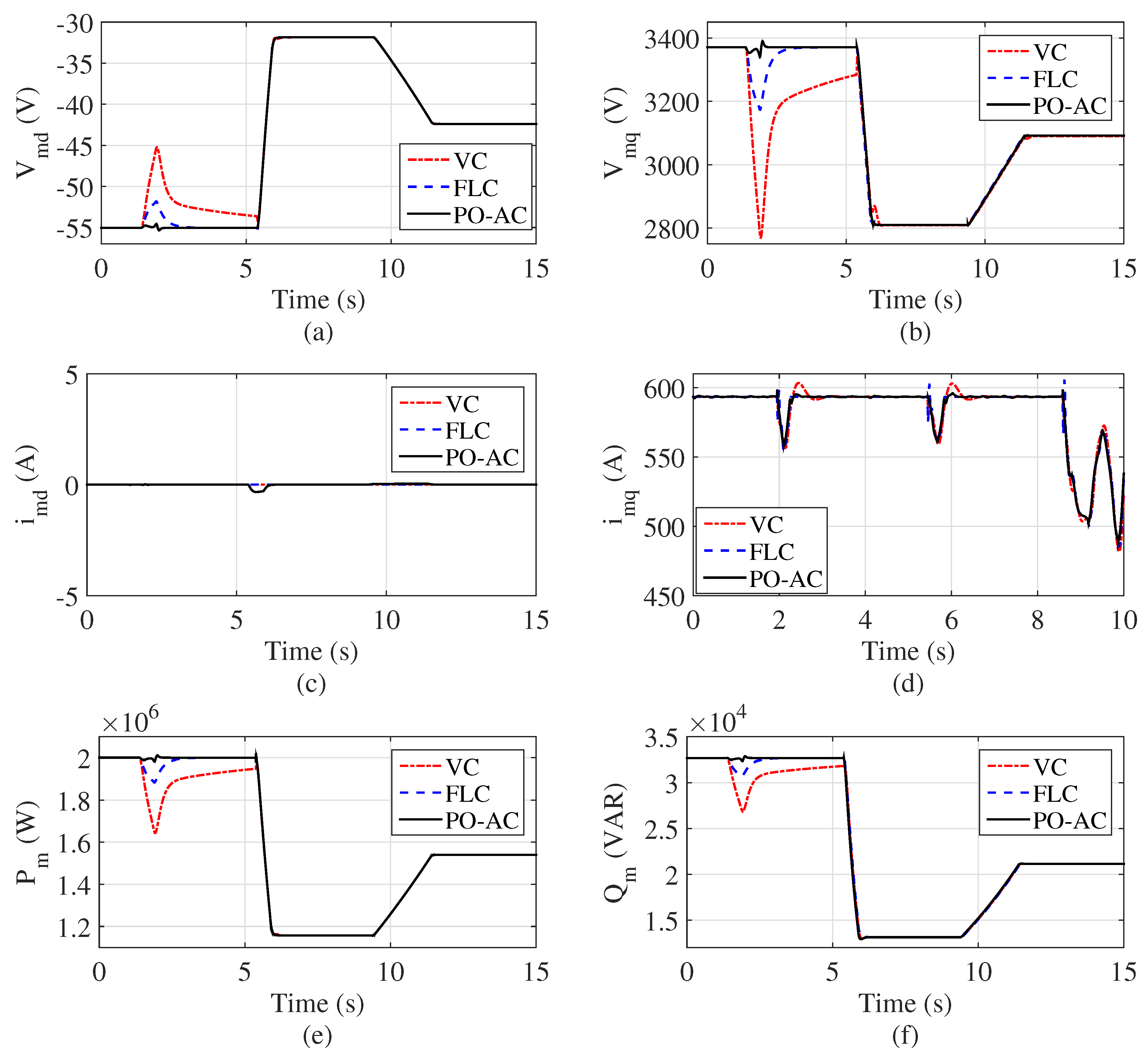
4.1. Ramp Wind Speed
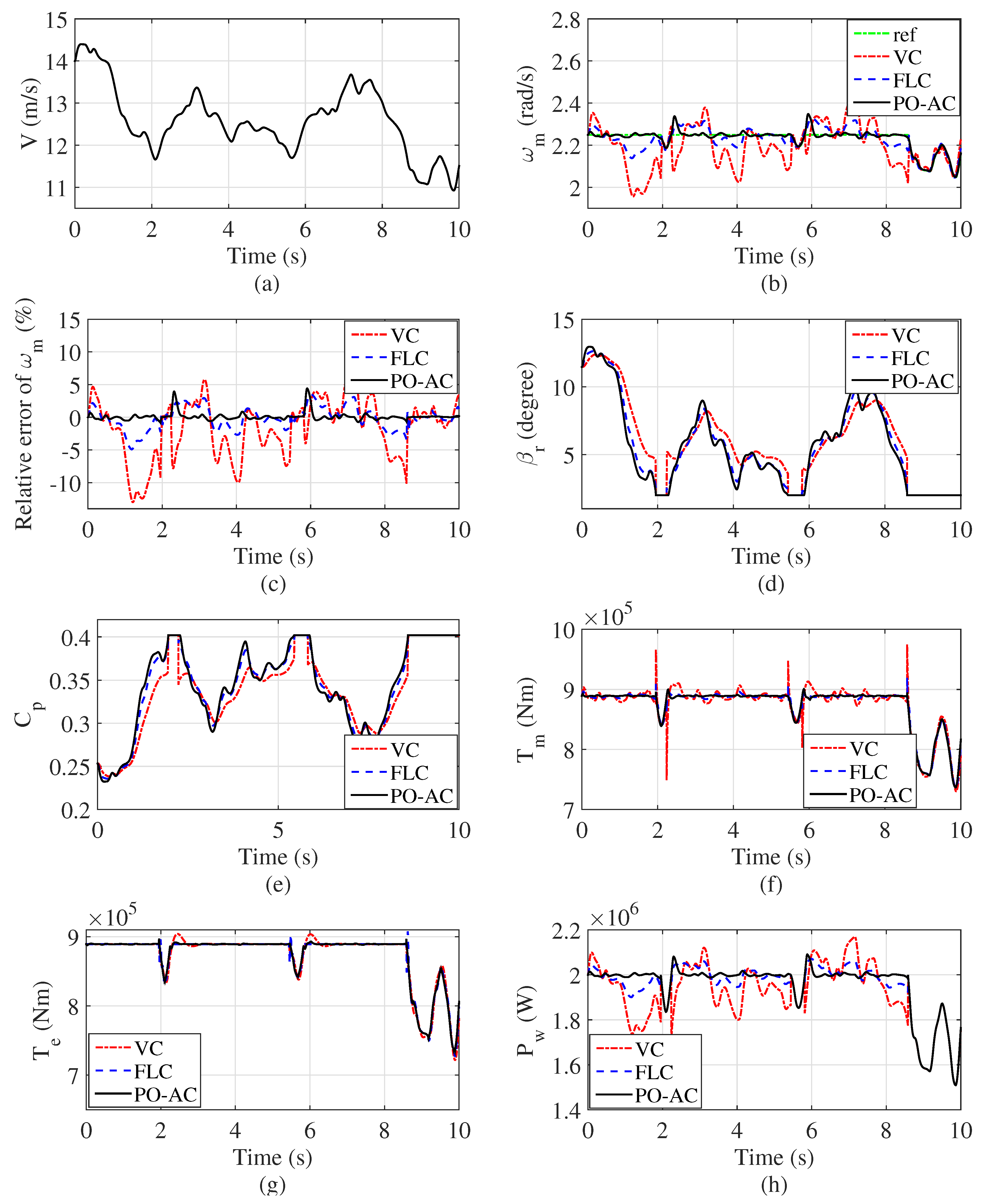
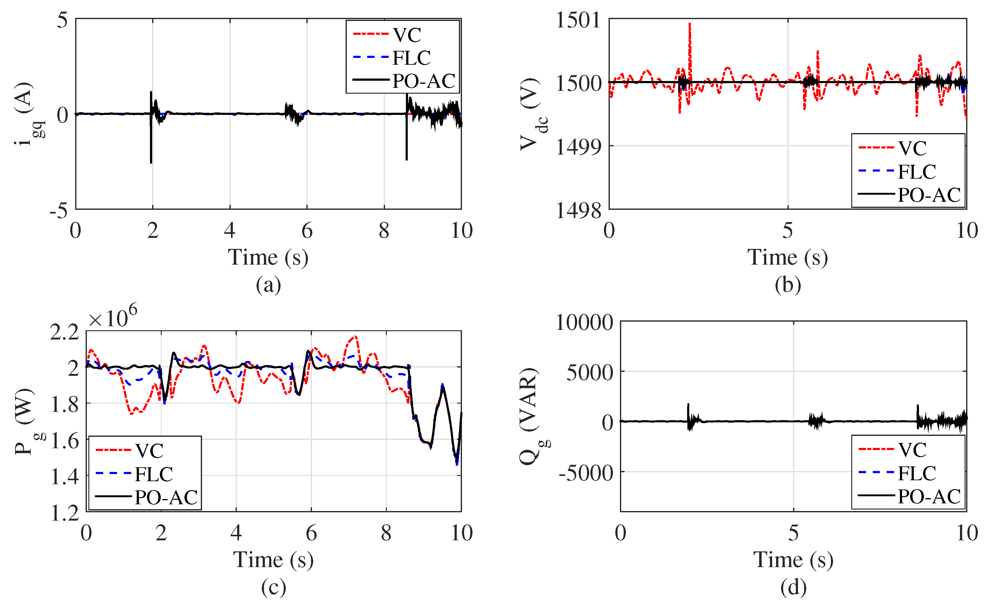
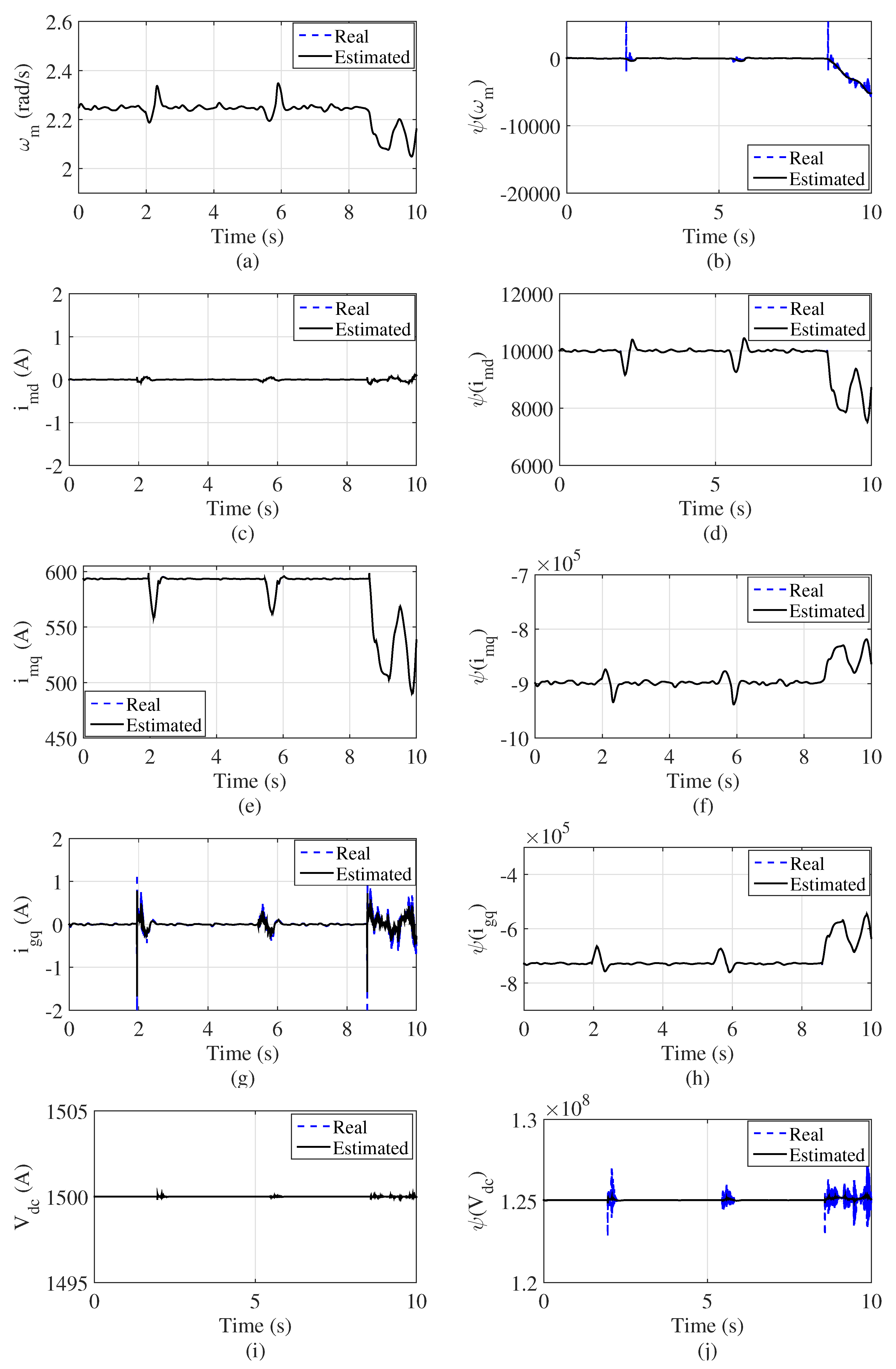
4.2. Random Wind Speed
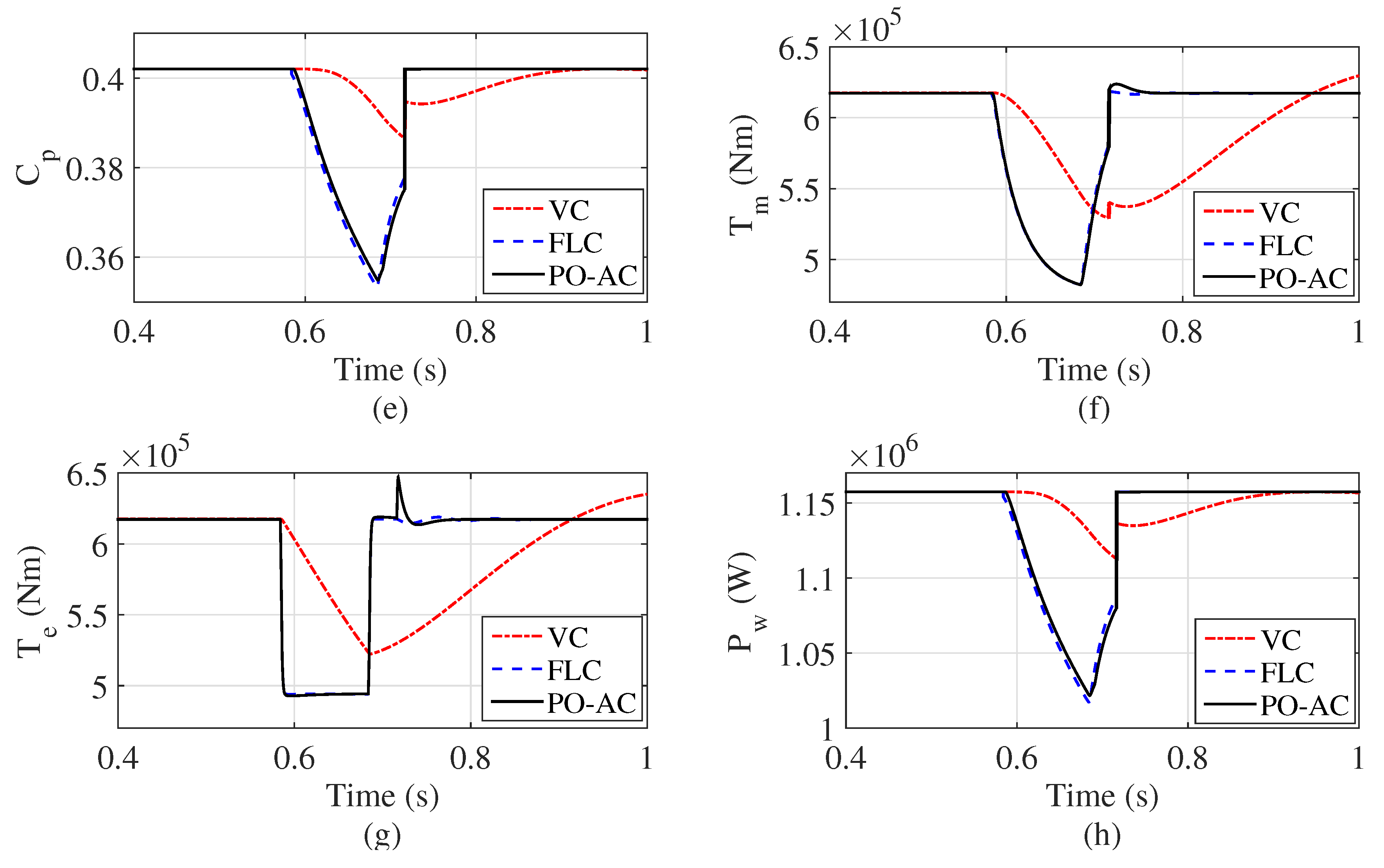
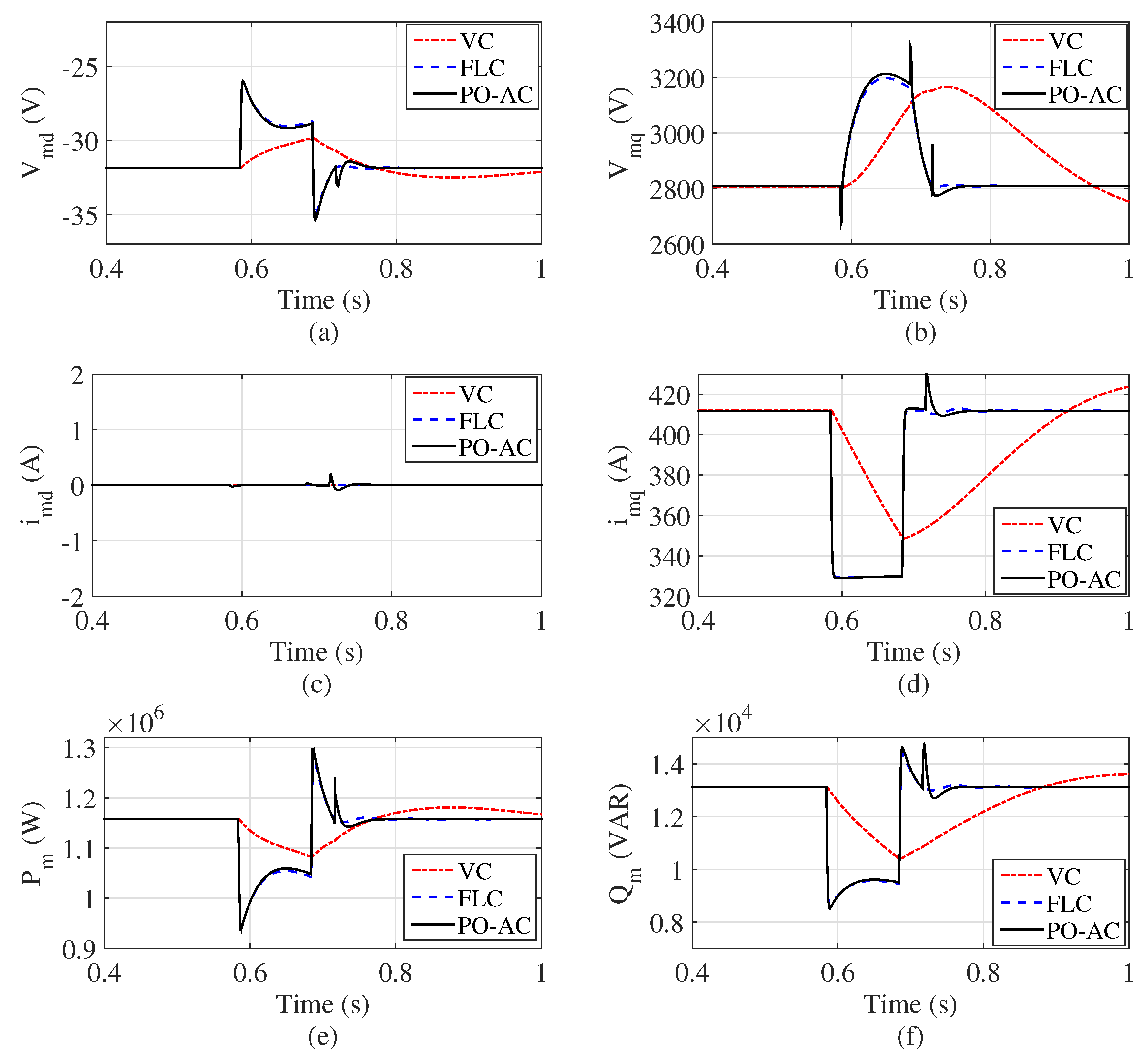
4.3. FRTC Compliance With the Pitch Control
5. Conclusions
Author Contributions
Funding
Conflicts of Interest
Abbreviations
| WECSs | Wind energy conversion systems |
| VSWTs | Variable-speed wind turbines |
| WT | Wind turbine |
| DFIGs | Doubly fed induction generators |
| PMSGs | Permanent magnet synchronous generators |
| GSC | Grid-side converter |
| MSC | Machine-side converter |
| FRTC | Fault ride-through capability |
| PMSG-WT | Permanent magnet synchronous generator based wind turbine |
| MPPT | Maximum power point tracking |
| FLC | Feedback linearisation control |
| VC | Conventional vector control with proportional-integral |
| PO-AC | Perturbation observer based adaptive control |
| LHP | Left-half plane |
References
- Yang, B.; Zhang, X.S.; Yu, T.; Shu, H.C.; Fang, Z.H. Grouped grey wolf optimizer for maximum power point tracking of doubly-fed induction generator based wind turbine. Energy Convers. Manag. 2017, 133, 427–443. [Google Scholar] [CrossRef]
- Liao, S.W.; Yao, W.; Han, X.N.; Wen, J.Y.; Cheng, S.J. Chronological operation simulation framework for regional power system under high penetration of renewable energy using meteorological data. Appl. Energy 2017, 203, 816–828. [Google Scholar] [CrossRef]
- Yang, B.; Jiang, L.; Yao, W.; Wu, Q.H. Nonlinear maximum power point tracking control and modal analysis of DFIG based wind turbine. Int. J. Electr. Power Energy Syst. 2016, 74, 429–436. [Google Scholar] [CrossRef]
- Haque, M.E.; Saw, Y.C.; Chowdhury, M.M. Advanced control scheme for an IPM synchronous generator- based gearless variable speed wind turbine. IEEE Trans. Sustain. Energy 2014, 5, 354–362. [Google Scholar] [CrossRef]
- Kim, Y.S.; Chung, I.Y.; Moon, S.I. An analysis of variable-speed wind turbine power-control methods with fluctuating wind speed. Energies 2013, 6, 3323–3338. [Google Scholar] [CrossRef]
- Liu, J.; Yao, W.; Wen, J.Y.; Fang, J.K.; Jiang, L.; He, H.B.; Cheng, S.J. Impact of power grid strength and PLL parameters on stability of grid-connected DFIG wind farm. IEEE Trans. Sustain. Energy 2019. [Google Scholar] [CrossRef]
- Said, B.; Hafedh, A.; Ahmed, E.H.; Mohamed, C. Comparative study of three types of controllers for DFIG in wind energy conversion system. Prot. Control Mod. Power Syst. 2018, 3, 214–225. [Google Scholar]
- Haque, M.E.; Negnevitsky, M.; Muttaqi, K.M. A novel control strategy for a variable-speed wind turbine with a permanent-magnet synchronous generator. IEEE Trans. Ind. Electron. 2010, 46, 331–339. [Google Scholar] [CrossRef]
- Chinchilla, M.; Arnaltes, S.; Burgos, J.C. Control of permanent-magnet generators applied to variable-speed wind-energy systems connected to the grid. IEEE Trans. Energy Convers. 2006, 21, 130–135. [Google Scholar] [CrossRef]
- Karakasis, N.E.; Mademlis, C.A. High efficiency control strategy in a wind energy conversion system with doubly fed induction generator. Renew. Energy 2018, 125, 974–984. [Google Scholar] [CrossRef]
- Yang, B.; Yu, T.; Shu, H.C.; Zhang, Y.M.; Chen, J.; Sang, Y.Y.; Jiang, L. Passivity-based sliding-mode control design for optimal power extraction of a PMSG based variable speed wind turbine. Renew. Energy 2018, 119, 577–589. [Google Scholar] [CrossRef]
- Liu, J.; Wen, J.Y.; Yao, W.; Long, Y. Solution to short-term frequency response of wind farms by using energy storage systems. IET Renew. Power Gener. 2016, 10, 669–678. [Google Scholar] [CrossRef]
- Seixas, M.; Relício, R.; Mendes, V.M.F. Fifth harmonic and sag impact on PMSG wind turbines with a balancing new strategy for capacitor voltages. Energy Convers. Manag. 2014, 79, 721–730. [Google Scholar] [CrossRef]
- Shen, Y.; Yao, W.; Wen, J.Y.; He, H.B.; Jiang, L. Resilient wide-area damping control using GrHDP to tolerate communication failures. IEEE Trans. Smart Grid 2019, 10, 2547–2557. [Google Scholar] [CrossRef]
- Corradini, M.L.; Ippoliti, G.; Orlando, G. Robust control of variable-speed wind turbines based on an aerodynamic torque observer. IEEE Trans. Control Syst. Technol. 2013, 21, 1199–1206. [Google Scholar] [CrossRef]
- Hansen, A.D.; Michalke, G. Multi-pole permanent magnet synchronous generator wind turbines’ grid support capability in uninterrupted operation during grid faults. IET Renew. Power Gener. 2009, 3, 333–348. [Google Scholar] [CrossRef]
- Li, S.H.; Haskew, T.A.; Swatloski, R.P.; Gathings, W. Optimal and direct-current vector control of direct-driven PMSG wind turbines. IEEE Trans. Power Electron. 2012, 27, 2325–2337. [Google Scholar] [CrossRef]
- Hong, C.M.; Chen, C.H.; Tu, C.S. Maximum power point tracking-based control algorithm for PMSG wind generation system without mechanical sensors. Energy Convers. Manag. 2013, 69, 58–67. [Google Scholar] [CrossRef]
- Xia, Y.; Ahmed, K.H.; Williams, B.W. A new maximum power point tracking technique for permanent magnet synchronous generator based wind energy conversion system. IEEE Trans. Power Electron. 2011, 26, 3609–3620. [Google Scholar] [CrossRef]
- Li, H.; Shi, K.L.; McLaren, P.G. Neural-network-based sensorless maximum wind energy capture with compensated power coefficient. IEEE Trans. Ind. Appl. 2005, 41, 1548–1556. [Google Scholar] [CrossRef]
- Abdullah, M.A.; Yatim, A.H.M.; Tan, W.C.; Saidur, R. A review of maximum power point tracking algorithms for wind energy systems. Renew. Sustain. Energy Rev. 2012, 16, 3320–3327. [Google Scholar] [CrossRef]
- Camblong, H. Digital robust control of a variable speed pitch regulated wind turbine for above rated wind speeds. Control Eng. Pract. 2008, 16, 946–958. [Google Scholar] [CrossRef]
- Kumar, A.; Stol, K. Simulating feedback linearization control of wind turbines using high-order models. Wind Energy 2009, 13, 419–432. [Google Scholar] [CrossRef]
- Boukhezzar, B.; Siguerdidjane, H. Nonlinear Control of a variable-speed wind turbine using a two-mass model. IEEE Trans. Energy Convers. 2011, 26, 149–162. [Google Scholar] [CrossRef]
- Tsili, M.; Papathanassiou, S. A review of grid code technical requirements for wind farms. IET Renew. Power Gener. 2009, 3, 308–332. [Google Scholar] [CrossRef]
- Lee, C.T.; Hsu, C.W.; Cheng, P.T. A low-voltage ride-through technique of grid-connected converters of distributed energy resources. IEEE Trans. Ind. Appl. 2011, 47, 1812–1832. [Google Scholar] [CrossRef]
- Kim, K.H.; Jeung, Y.C.; Lee, D.C.; Kim, H.G. LVRT scheme of PMSG wind power systems based on feedback linearization. IEEE Trans. Power Electron. 2012, 27, 2376–2384. [Google Scholar] [CrossRef]
- Popat, M.; Wu, B.; Zargari, N.R. Fault ride-through capability of cascaded current-source converter-based offshore wind farm. IEEE Trans. Sustain. Energy 2013, 4, 314–323. [Google Scholar] [CrossRef]
- Iov, F.; Hansen, A.; Sorensen, P.; Cutululis, N. Mapping of Grid Faults and Grid Codes; Risoe National Laboratory, Technical University of Denmark: Copenhagen, Denmark, 2007. [Google Scholar]
- Yang, J.; Gao, Y.J.; O’Reilly, J. Permanent magnet synchronous generator converter protection analysis during DC wind farm open-circuit fault condition. In Proceedings of the 2009 IEEE Electrical Power & Energy Conference (EPEC), Montreal, QC, Canada, 22–23 October 2009; pp. 1–6. [Google Scholar]
- Noureldeen, O.; Hamdan, I. A novel controllable crowbar based on fault type protection technique for DFIG wind energy conversion system using adaptive neuro-fuzzy inference system. Prot. Control Mod. Power Syst. 2018, 3, 328–339. [Google Scholar] [CrossRef]
- Rizo, M.; Rodriguez, A.; Bueno, E.; Rodriguez, F.J.; Giron, C. Low voltage ride-through of wind turbine based on interior permanent magnet synchronous generators sensorless vector controlled. In Proceedings of the 2010 IEEE Energy Conversion Congress and Exposition, Atlanta, GA, USA, 12–16 September 2010; pp. 2507–2515. [Google Scholar]
- Seman, S.; Niiranen, J.; Arkkio, A. Ride-through analysis of doubly fed induction wind-power generator under unsymmetrical network disturbance. IEEE Trans. Power Syst. 2006, 21, 1782–1789. [Google Scholar] [CrossRef]
- Dai, J.Y.; Xu, D.W.; Wu, B.; Zargari, N.R. Unified DC-Link current control for low-voltage ride-through in current-source-converter-based wind energy conversion systems. IEEE Trans. Power Electron. 2011, 26, 288–297. [Google Scholar]
- Liang, J.Q.; Qiao, W.; Harley, R.G. Direct transient control of wind turbine driven DFIG for low voltage ride-through. In Proceedings of the 2009 IEEE Power Electronics and Machines in Wind Applications, Lincoln, NE, USA, 24–26 June 2009; pp. 1–7. [Google Scholar]
- Grilo, A.P.; Mota, A.S.A.; Mota, L.T.M.; Freitas, W. An analytical method for analysis of large-disturbance stability of induction generators. IEEE Trans. Power Syst. 2007, 22, 1861–1869. [Google Scholar] [CrossRef]
- Vrionis, T.; Koutiva, X.; Vovos, N.; Giannakopulos, G. Control of an HVDC link connecting a wind farm to the grid for fault ride-through enhancement. IEEE Trans. Power Syst. 2007, 22, 2039–2047. [Google Scholar] [CrossRef]
- Conroy, J.F.; Watson, R. Low voltage ride-through of a full converter wind turbine with permanent magnet generator. IET Renew. Power Gener. 2007, 1, 182–189. [Google Scholar] [CrossRef]
- Mullane, A.; Lightbody, G.; Yacamini, R. Wind turbine fault ride through enhancement. IEEE Trans. Power Syst. 2005, 20, 1929–1937. [Google Scholar] [CrossRef]
- Matas, J.; Castilla, M.; Guerrero, J.M.; Garcia de Vicuna, L.; Miret, J. Feedback linearization of direct-drive synchronous wind turbines via a sliding mode approach. IEEE Trans. Power Electron. 2008, 23, 1093–1103. [Google Scholar] [CrossRef]
- Matas, J.; Rodriguez, P.; Guerrero, J.M.; Vasquez, J.C. Ride through improvement of wind-turbines via feedback linearization. In Proceedings of the 2008 IEEE International Symposium on Industrial Electronics, Cambridge, UK, 30 June–2 July 2008; pp. 2377–2382. [Google Scholar]
- Valenciaga, F.; Puleston, P.F.; Battaiotto, P.E. Variable structure system control design method based on a differential geometric approach to a wind energy conversion subsystem. IEE Proc.-Control Theory Appl. 2004, 151, 6–12. [Google Scholar] [CrossRef]
- Hosseinzadeh, M.; Rajaei Salmasi, F. Analysis and dection of a wind system failure in a micro-grid. J. Renew. Sustain. Energy 2016, 8, 043302. [Google Scholar] [CrossRef]
- Hosseinzadeh, M.; Yazdanpanah, M.J. Performance enhanced model reference adaptive control through switching non-quadratic Lyapunov functions. Syst. Control Lett. Syst. 2015, 76, 47–55. [Google Scholar] [CrossRef]
- Chen, J.; Jiang, L.; Yao, W.; Wu, Q.H. Perturbation estimation based nonlinear adaptive control of a full-rated converter wind-turbine for fault ride-through capability enhancement. IEEE Trans. Power Syst. 2014, 29, 2733–2743. [Google Scholar] [CrossRef]
- Yang, B.; Yu, T.; Shu, H.C.; Dong, J.; Jiang, L. Robust sliding-mode control of wind energy conversion systems for optimal power extraction via nonlinear perturbation observers. Appl. Energy 2018, 210, 711–723. [Google Scholar] [CrossRef]
- Chen, J.; Yao, W.; Zhang, C.K.; Ren, Y.X.; Jiang, L. Design of robust MPPT controller for grid-connected PMSG-Based wind turbine via perturbation observation based nonlinear adaptive control. Renew. Energy 2019, 134, 478–495. [Google Scholar] [CrossRef]
- Uehara, A.; Pratap, A.; Goya, T.; Senjyu, T.; Yona, A.; Urasaki, N.; Funabashi, T. A coordinated control method to smooth wind power fluctuations of a PMSG-based WECS. IEEE Trans. Energy Convers. 2011, 26, 550–558. [Google Scholar] [CrossRef]
- Jiang, L.; Wu, Q.H.; Wen, J.Y. Decentralized nonlinear adaptive control for multimachine power systems via high-gain perturbation observer. IEEE Trans. Circuits Syst. I Regul. Pap. 2004, 51, 2052–2059. [Google Scholar] [CrossRef]
- Jiang, L.; Wu, Q.H. Nonlinear adaptive control via sliding-mode state and perturbation observer. IEE Proc. Inst. Electr. Eng.-Control Theory Appl. 2002, 149, 269–277. [Google Scholar] [CrossRef]
- Tao, G. Model reference adaptive control with L1+α tracking. Int. J. Control. 1996, 64, 859–870. [Google Scholar] [CrossRef]
- Alepuz, S.; Calle, A.; Busquets-Monge, S.; Kouro, S.; Wu, B. Use of stored energy in PMSG rotor inertia for low-voltage ride-through in back-to-back NPC converter-based wind power systems. IEEE Trans. Ind. Electron. 2013, 60, 1787–1796. [Google Scholar] [CrossRef]
- Heier, S. Grid Integration of Wind Energy Conversion Systems; Wiley: Hoboken, NJ, USA, 2006. [Google Scholar]


| Parameters of the adaptive controller | |
| Gains of observer (12) | , , , |
| Gains of observer (19) | , , |
| Gains of observer (20) | , , |
| Gains of linear controller | , , , |
| Simulation Scenarios | Variables | Controllers | ||
|---|---|---|---|---|
| VC | FLC | PO-AC | ||
| Ramp wind speed | 0.5116 | 0.09338 | ||
| Random wind speed | 0.814 | 0.2949 | ||
| FRTC compliance with the pitch control | 0.04794 | 0.02485 | ||
| 0.1299 | 0.01892 | 0.01419 | ||
© 2019 by the authors. Licensee MDPI, Basel, Switzerland. This article is an open access article distributed under the terms and conditions of the Creative Commons Attribution (CC BY) license (http://creativecommons.org/licenses/by/4.0/).
Share and Cite
Chen, J.; Duan, W.; Yang, X.; Zhang, L.; Shan, Y.; Yang, B.; Shu, H.; An, N.; Yu, T. Overall Adaptive Controller Design of PMSG Under Whole Wind Speed Range: A Perturbation Compensation Based Approach. Processes 2019, 7, 732. https://doi.org/10.3390/pr7100732
Chen J, Duan W, Yang X, Zhang L, Shan Y, Yang B, Shu H, An N, Yu T. Overall Adaptive Controller Design of PMSG Under Whole Wind Speed Range: A Perturbation Compensation Based Approach. Processes. 2019; 7(10):732. https://doi.org/10.3390/pr7100732
Chicago/Turabian StyleChen, Jian, Wenyong Duan, Xiaodong Yang, Lanhong Zhang, Yi Shan, Bo Yang, Hongchun Shu, Na An, and Tao Yu. 2019. "Overall Adaptive Controller Design of PMSG Under Whole Wind Speed Range: A Perturbation Compensation Based Approach" Processes 7, no. 10: 732. https://doi.org/10.3390/pr7100732
APA StyleChen, J., Duan, W., Yang, X., Zhang, L., Shan, Y., Yang, B., Shu, H., An, N., & Yu, T. (2019). Overall Adaptive Controller Design of PMSG Under Whole Wind Speed Range: A Perturbation Compensation Based Approach. Processes, 7(10), 732. https://doi.org/10.3390/pr7100732