1. Introduction
1.1. Background
New product development (NPD) is a key success factor for growing organizations, as they are constantly re-engineering and developing new products to stay competitive [
1,
2]. Transitioning new products from the research and development (R&D) stage to the prototyping stage, and finally to the manufacturing stage is a common problem for organizations of all sizes [
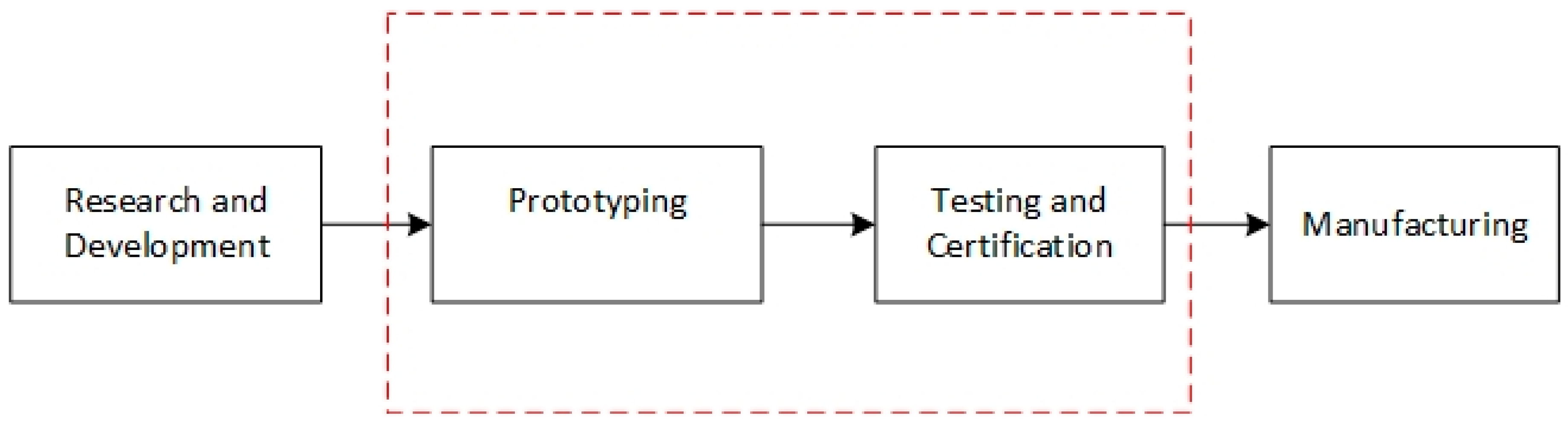
3]. The stages of NPD from an engineering perspective are shown in
Figure 1.
The middle phase of the NPD process highlighted in
Figure 1 is often the most difficult phase, due to cost and time constraints; especially for innovative start-up firms and small organizations [
4]. In the case of polymer products, injection molding (IM) is one of the most widely used polymer processing techniques. Conventionally, IM tools are machined out of blocks of steel, aluminium, or copper–beryllium alloys, and the choice of mold material is dependent on factors such as the molding material, the complexity of the part, the required life, and the available budget [
5,
6,
7]. In cases of low-volume production, the capital cost of the injection molds is the largest cost component of an injection molded part, followed by the molding material and the processing costs [
8]. Complex product geometry requires complex tooling, which increases the cost and lead times if manufactured by conventional methods, which does not work well for keeping the costs of prototype tooling low [
6,
9]. Hence, the NPD process for injection molded parts typically faces issues (delays) during the prototyping and testing phases. Since more than 35% by weight of all polymers is by IM, the highest demand for low cost tooling is from the IM industry [
8]. To stay competitive, industries are looking to reduce the wastage of raw materials, shorten product lead times, and eliminate the need for expensive tooling [
10]. In the above situations, industries increasingly turn to additive manufacturing (AM) to solve these challenges via direct part production [
11]. However, there are disadvantages: lack of material availability; varied material properties; inaccurate representations of the final part; poor surface finish. For accurate evaluations of a prototype, industries prefer to manufacture prototypes by using the same materials and the same process as the final part. In such situations, industries may use rapid tooling (RT).
1.2. Polymer Rapid Tooling (PRT)
RT is a process that uses AM techniques to build tools at low cost. RT negates the need for complex conventional machining operations and direct labor, and instead uses an additive approach of building objects layer by layer [
12,
13]. The initial push for developing objects quickly without the need for complex tooling came from the American automotive industry [
14]. RT involves both the use of polymer and metal AM systems. However, the cost of metal AM systems and operating consumables are significantly higher than polymer-based AM systems. Rapid Tools built using polymer AM systems are referred to as polymer rapid tooling (PRT). Fluid-based AM processes such as Stereolithography (SLA) and Material Jetting (MJ) are the most commonly used processes for manufacturing PRT inserts for injection molding. Selective laser sintering (SLS) and fused deposition modelling (FDM) have also been used, but not as commonly as the fluid-based AM processes [
15].
1.3. Failure of Polymer Rapid Tools
This section deals with the various types of failures, and their causes as presented in the literature. Most of the failures were classified as mechanical failures that occurred due to high injection pressure and higher melt temperature. The second most common reason of failure was due to insufficient draft on the walls of the tool. Several suggestion have also been identified by authors to improve tool life and to avoid failure.
1.3.1. Failures Due to Mold and Melt Temperature
The first PRT inserts made using SLA technology were not robust, and they failed during the start-up of the injection molding process; they had a very low thermal conductivity, which caused thermal degradation, and resulted in mechanical failure [
16]. The life of a PRT insert is largely dependent on the resin being molded, and the molding parameters in use [
17]. The co-efficient of thermal expansion in polymers varies with the temperature; at temperatures above the glass transition temperature (
Tg) of the material, the co-efficient of expansion increases significantly. This causes the mold to expand drastically and sometimes fail [
18]. Adjusting the process parameters to keep the tool temperature below its glass transition temperature (
Tg), to avoid softening of the tool, is one suggested solution to avoid such failure [
19]. However, this solution is only possible if the molding polymer allows a lower mold temperature; for polycarbonates requiring higher mold temperatures, it is not applicable.
1.3.2. Failures Due to Injection Pressure
Failure typically occurs after several shots. Since the shear and bending forces induced by IM should not increase, it is therefore suggested that failure occurs due to a change in the mechanical properties of the tool [
16]. PRT inserts were seen to be deforming and failing catastrophically, due to the pressure exerted by the molten polymer during the injection and packing stages of the molding process [
20]. Inserts tend to fail if the stresses created by the flowing polymer are more than the yield strength of the tool at that temperature [
21]. The injection of the polymer is also known to cause stresses on features, which may lead to crack propagation and the eventual failure of the insert [
22]. Static friction between the polymer mold and part determine the ejection force, and the static friction increases with an increase in the mold surface area. Cooling cycles can determine the amount of shrinkage, and thereby the ejection forces as well; higher ejection forces will lead to tool wear and gradual failure [
17]. The surface roughness of molds plays an important role in the ejection forces; small build-up layers and high gloss-finished molds experience smaller ejection forces [
23]. There is also a possibility of surface smoothening over the life of molds which can be good for tool life, but they can lead to excessive flashing. 3D-printed tool designers have recommend having draft angles of about 5% in polymer molds for the ease of ejection of parts; higher draft angles will lead to easier part ejections [
24].
1.4. Opportunities for Development
SLA-based materials such as Accura Bluestone
® from 3D systems [
25], and Somos
® Perform from DSM [
26], are more suited for produce PRT inserts than the MJ materials, such as Digital ABS and Visijet M3-X reported in this paper [
27]. These materials contain reinforcement, and they have better thermal performance. However, the cost of the AM machines that are required to print these materials is high, and is generally not accessible to smaller industries. The journal literature for polymer-based RT is predominantly based on the SLA process, and it lacks data for other processes such as MJ and FDM.
The cost of the AM machines and material used in the MJ process are significantly lower compared to the SLA process. Hence, there is still a place for RT tools that are printed via the MJ process. This is especially for start-ups and small organizations, where keeping costs low is one of the biggest challenges. Currently there is ongoing work into the use of the MJ process to create low-cost PRT inserts, and methods for strengthening the PRT inserts. The application of metal layers (coatings) onto the PRT inserts has been suggested to improve their properties, such as wear resistance and hardness [
28,
29]. Compositing FDM parts with high-strength resins filled into the voids printed has also been known to improve the strength of the PRT inserts [
30]. However, PRT inserts made from the MJ process tend to fail abruptly, and they have life issues. The life of these inserts is dependent on factors that are not very well documented. Understanding the failure modes and the possible causes of failure, and developing a process to prolong the tool life can be quite beneficial for creating low-cost tooling.
Therefore, this paper focuses on the categorization of failures that occur during the injection molding process, using PRT inserts manufactured by the material jetting technique.
1.5. Aim
PRT inserts lack the strength and robustness of conventional steel and aluminium inserts, and they typically only last for 50–100 shots before the surface starts deteriorating, and features on the insert begin to fail. The materials for PRT inserts made from the MJ process are cross-linked polymer systems (thermosets). These do not necessarily have a melting temperature, but instead have a glass transition temperature (Tg). Digital ABS®, the most commonly used material for PRT, has a Tg of 53 °C. The current industrial trend is to use PRT inserts to mold polymers with relatively low processing temperatures of about 150–200 °C. These include commodity resins such as polypropylene (PP), acrylonitrile butadiene styrene (ABS), and polystyrene (PS). These resins have a good melt flow index, and they require mold temperatures in the range of 45–50 °C which is below the Tg of Digital ABS®. Lexan-943-A® is a resin that is commonly used by the aerospace industry for cabin interiors. However, the mold temperature that is required for molding Lexan-943-A is 80–95 °C, which is higher than the Tg of Digital ABS®, and the processing temperature is in the range of 285–315 °C. This presents a challenging opportunity to develop a process that would help in achieving low volume production (10–100 parts) of aerospace cabin interior parts (polymer) using PRT inserts.
The main aim of this study was to identify and categorize the different failures that occur in a PRT insert when it is used for injection molding resins with processing temperatures of above 275 °C. We are particularly interested in analyzing real-world components, and determining the best practices for users. An understanding of failure modes and the underlying mechanisms will help with predictions of tool failure, and assist with improvements in the operating life of PRT inserts.
2. Materials and Methods
We applied a case study methodology to real production parts. Three case studies were performed, of progressive complexity, both in terms of molding and part geometry. The first case study was a standard test specimen used for flame and toxicity testing in the aerospace industry; the geometry was flat and did not involve any complex features. The challenge in case study 1 was to completely fill the mold without damaging the PRT insert. The second case study was an electronic enclosure used in the navigation industry; the geometry was complex, as it had features such as thin walls, bosses, and ribs. The third case study was a finger guard used in the aerospace industry; the mold geometry did not have a flat parting line, and had walls with no draft on them. The complexity in case study 3 was to avoid scalding of the tool due to the lack of air vents. The details of the case studies are shown in
Table 1.
In all of the case studies, the molding was been performed with an aerospace resin: Lexan 943-A. The key issues are that the mold temperature required for processing Lexan 943-A is higher than the Tg of the PRT material. Hence the mold is operating under conditions of extreme thermal overload.
The case studies were devised based on a progressive regime of improving the tool life of PRT inserts. The findings from how the failures occurred in case study 1 were used to inform the design of case study 2, etc. For example, case study 1 gave important insights into the need to control the injection pressure to avoid failure at first shot, and case study 2 gave insights into the cooling time. The PRT insert from case study 1 that had failed on the fifth shot was examined; the runner wall had sheared, due to the incoming melt pressure. For case study 2, we used a low injection pressure, and built it up over each shot, until the pressure was sufficient to fill the cavity. The mold surface and features were examined after each shot, for any potential defects. If any defects such as chipping, erosion, or cracks were observed, the parameters for that shot were highlighted. Shot size, melt temperature, and mold temperature were all kept constant; the injection pressure was increased until it was sufficient to fill approximately 85% of the mold. Examinations were done on the failure regions to determine the type and cause of the failure.
The process for setting up each case study, and for extracting failure insights is shown in
Figure 2.
The different failures observed in the PRT inserts occurred at different times during the molding cycle. We identified the shot number, during which we first observed the signs of each failure type. Each part was inspected to detect failures, and likewise the tool. We continued the molding process, while the tool damage was minor (surface deterioration, surface scalding, bending), and terminated the test when catastrophic tool failure occurred.
2.1. Case Study Setups
2.1.1. Case Study 1—FAR Test Specimen
The flame and toxicity testing for aerospace parts are performed, according to the standard tests specified in Federal Aviation Regulation (FAR) 25.853 and FAR 25.855. FAR 25.853 requires the standard test specimen to be manufactured via the same process as the final part. The part chosen for this case study was a standard test specimen used for the vertical Bunsen burner test for cabin and cargo compartment materials. It is a flat rectangular plate (304.80 × 50.80 × 2.56 mm), and the solid model that was used for printing the core insert is shown in
Figure 3.
SOLIDWORKS 2016
® was used to design the core and cavity inserts. The inserts were printed on a Stratasys OBJET 350 Connex 3 Polyjet Machine. Digital ABS
® was the material that was used for printing the inserts with a 30-micron layer height setting, and glossy print mode was used. The inserts were fitted into a standard master unit die (MUD) base, and a 230-ton TOYO IM machine was used. No post-processing was done, other than water jet cleaning of the inserts to remove the wax support material. The process parameters used for injection molding is shown in
Table 2.
2.1.2. Case Study 2—Electronic Enclosure
Case study 2 represents a part with more complex geometric features, including a boss, thin walls, and thin core pins; see
Figure 4. An aerospace resin Lexan 943-A from Sabic Australia PTY LTD Melbourne was injected. The part chosen was already in production using a steel insert, and was used as a reference. The inserts were printed on a Stratasys OBJET 350 Connex 3 Polyjet Machine from Stratasys, Minnesota, United States. Digital ABS
® from Stratasys, Minnesota, United States was the material used for printing the inserts, with a 30 micron layer height setting and glossy print mode being used. The inserts were not hand-polished, as there was a risk of damaging the parting surface. A 450 ton injection molding machine with a maximum injection pressure of 170 MPa was used. The mold temperature was set at 45 °C to keep the tool below its
Tg, which is about 53 °C. The recommended mold temperature from the resin supplier was 105 °C.
Table 3 compares the process parameters for the meal molds recommended by the resin supplier, and the parameters used for the study.
2.1.3. Case Study 3—Aerospace Part
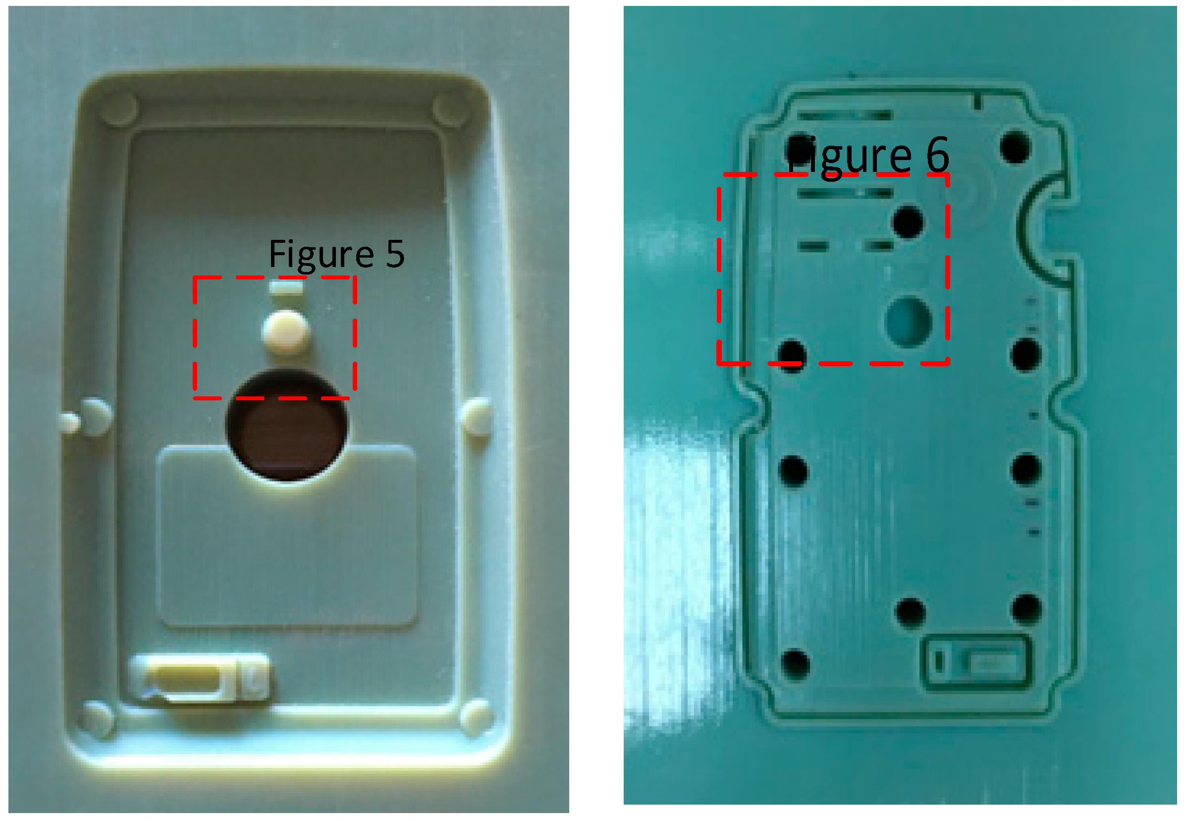
For case study 3, we used a production part for the aerospace industry; see
Figure 5, which shows the core and cavity insert. The inserts were printed onto a 3D systems ProJet MJP 3600 series printer from 3D systems, South Carolina, United States. The material used was Visijet M3-X
® from 3D systems, South Carolina, United States. An ultra-high definition (750 × 750 dpi) print mode with a 29 µm layer thickness setting was used to print the inserts. For post processing, the inserts were placed in an oven at 100 °C for 1 h; they were then cooled and scrubbed with a hot detergent to remove all the wax (support material).
A modified method of the process parameter settings was used for the initial start-up process. A Moldex3D flow simulation were used to determine the process parameters. The process parameters used for the study are shown in
Table 4.
3. Results
Various common failures were identified during the three case studies. We have categorized the failures into three failure modes: surface failures (crack formation); delamination (crack growth); feature failure (fracture). The individual failure mechanisms are described below.
3.1. Surface Failures (Stage 1—Crack Formation)
3.1.1. Surface Deterioration/Micro-Spallation
As the molten polymer enters the cavity, it begins to cool, while the PRT inserts begin to rise in temperature; at a certain stage of the molding cycle, the tool temperature is above the
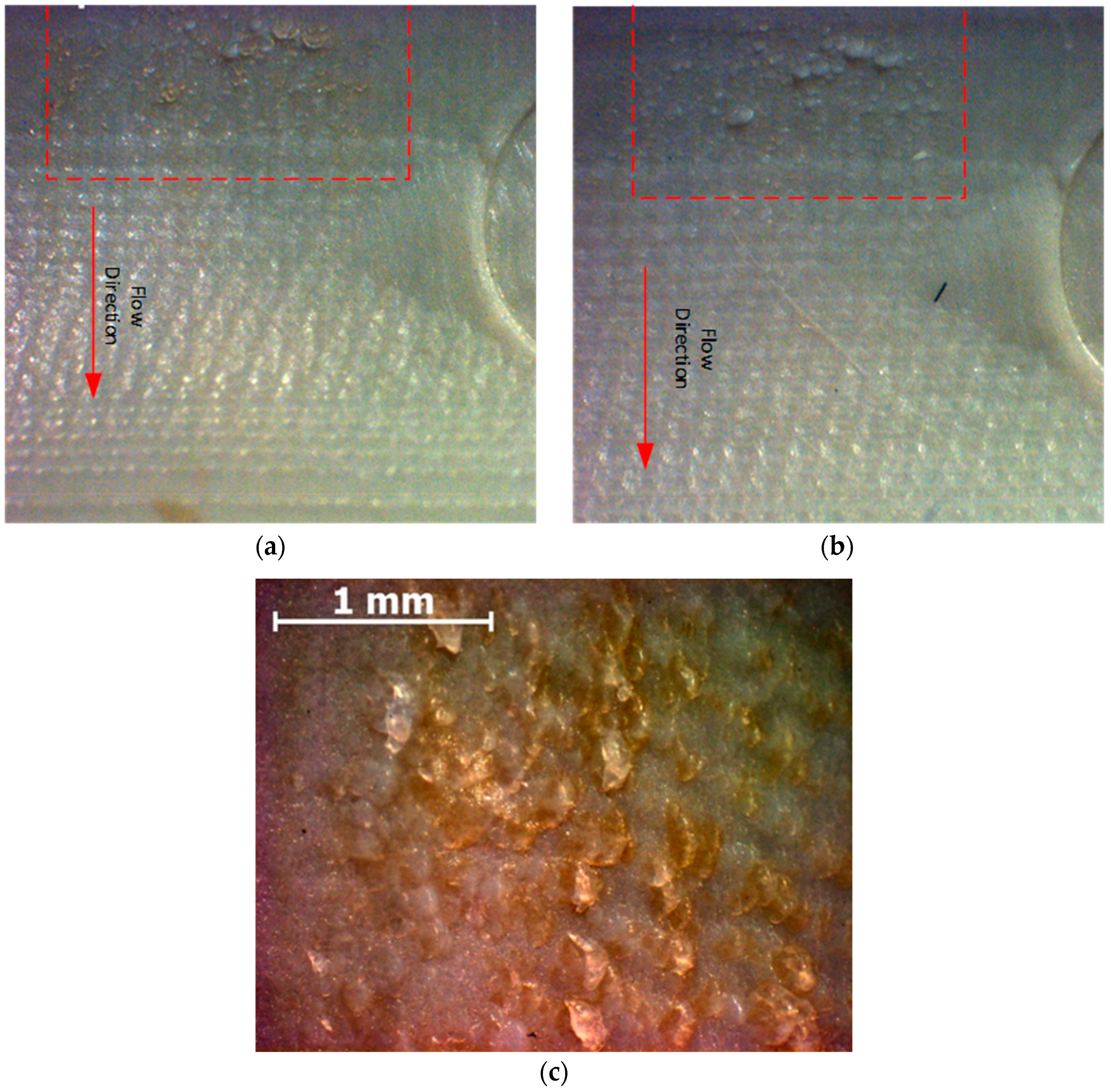
Tg of the tooling material, which causes the tool to soften. During the injection stage, as the polymer flows, there is a constant shear between the molten polymer and the top surface of the tool, resulting in erosion/spallation of the tool. The erosion tends to increase, with polymers having a low melt flow index, as they usually require a higher injection pressure. The erosion was microscopic, and could not be seen by the naked eye on the inserts in between shots, and the tool surface had failed completely by the end of the production cycle. The surface erosion was detected only when the parts were viewed by using a microscope. In
Figure 6a, the brown protrusions are pieces of the tool material that have been eroded and stuck to the part, thus creating small voids over the tool surface. Since the tool surface is no longer flat, the next molded part will have protrusions that are similar to the eroded area. In
Figure 6b, similar protrusions are evident as in
Figure 6a, but now they are the same color as the part. The surface degradation worsened after each shot. A magnified image of the deteriorated surface can be seen in
Figure 6c; the magnified image shows both the protrusions molded from the previous shot in white, and the brown protrusions are new fragments of the eroded surface from the current shot.
After each molding cycle, the parts were inspected for quality, and once the part showed any signs of quality defect, we inspected the tool to assess tool damage. No quality defect was identified for the first six shots. A small area of deteriorated surface was seen on the seventh shot, on the tool and the part. The surface deterioration worsened after each subsequent shot.
3.1.2. Surface Scalding
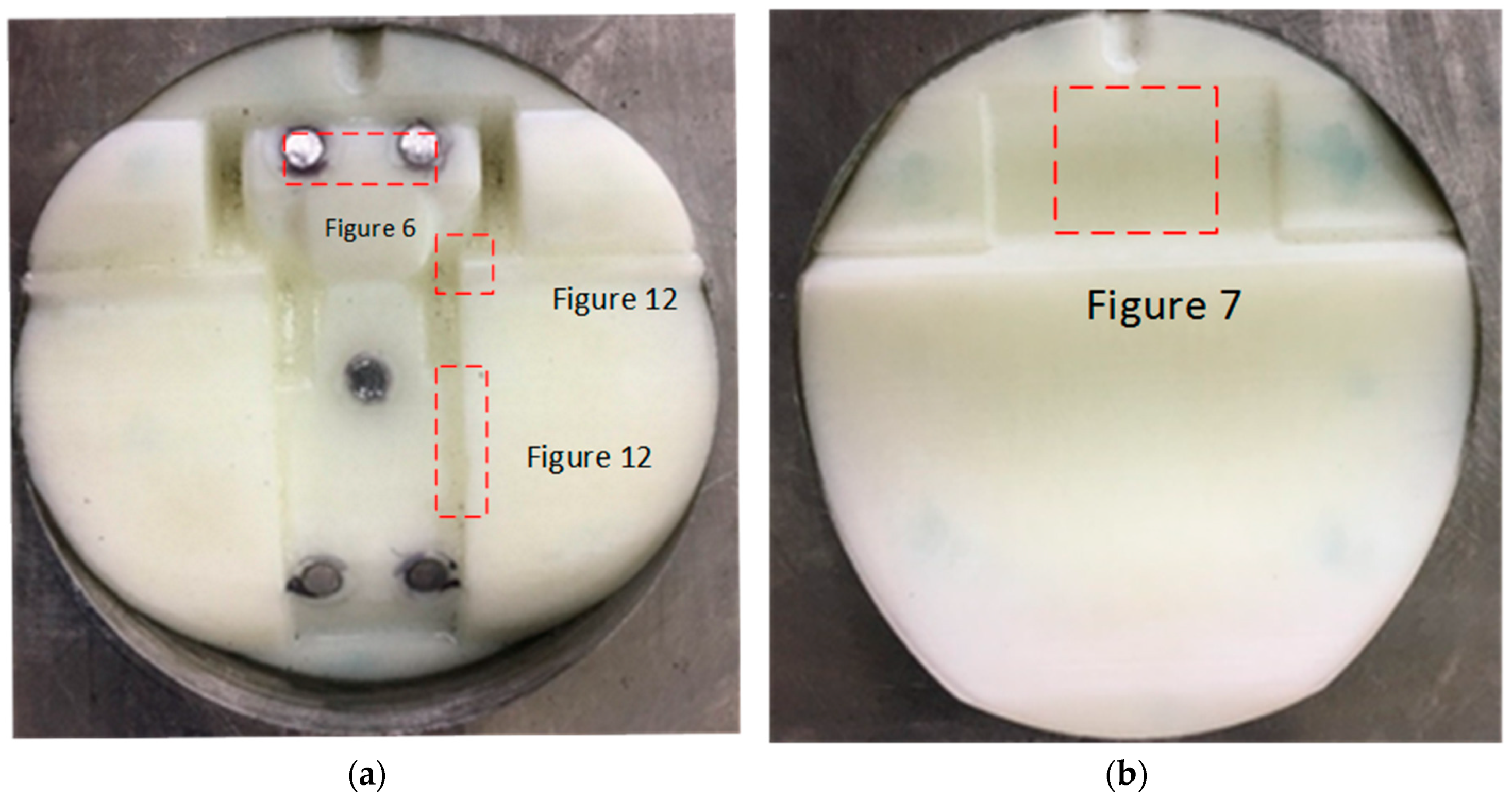
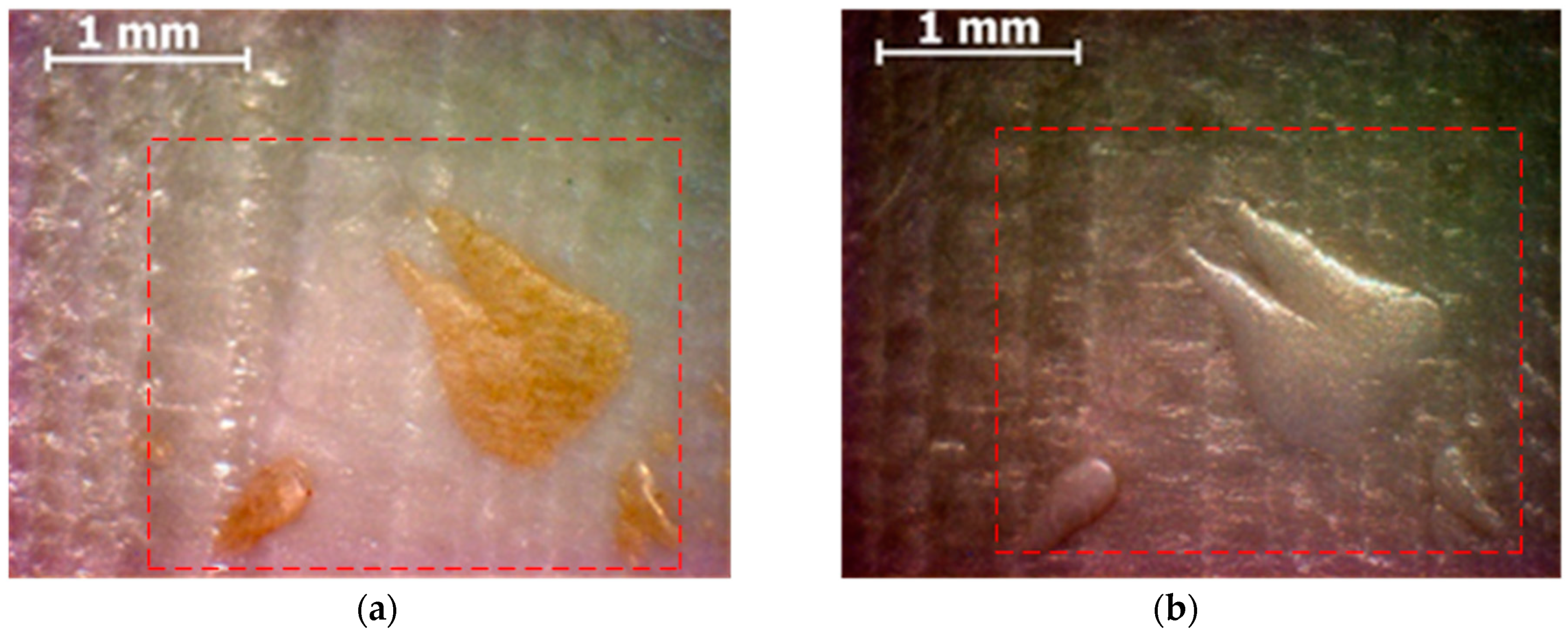
Surface scalding refers to the burning of the tool surface, due to the incoming polymer melt or the hot air/gases developed during the molding process. This damage mode is characterized by browning of the tool in small patches, see
Figure 7. Since MJ resins are thermosets, they do not melt; at higher temperatures, they usually degrade. Even though the tool temperature was kept below the
Tg (53 °C) of the tooling material before every shot, the tool temperature would rise as the molten polymer entered the tool. The first two case studies had a planar parting surface, which made it easier for air vents to be printed, but for case study 3, the part had a curved parting surface, and the faces were intersecting with the MUD base, and hence, no air vents were printed on the tool. Surface scalding was not seen in the first two case studies, and was only seen in the third case and lack of air venting was suspected to be one of the reasons for the tool degradation. In addition, the periphery of the tool had discolored, and showed signs of scalding. This failure was evident at the 12th molding shots. This rapidly progressed to catastrophic failure at the 13
th shot, as the tool surface material was removed.
3.2. Avulsion/Delamination (Stage 2—Crack Growth)
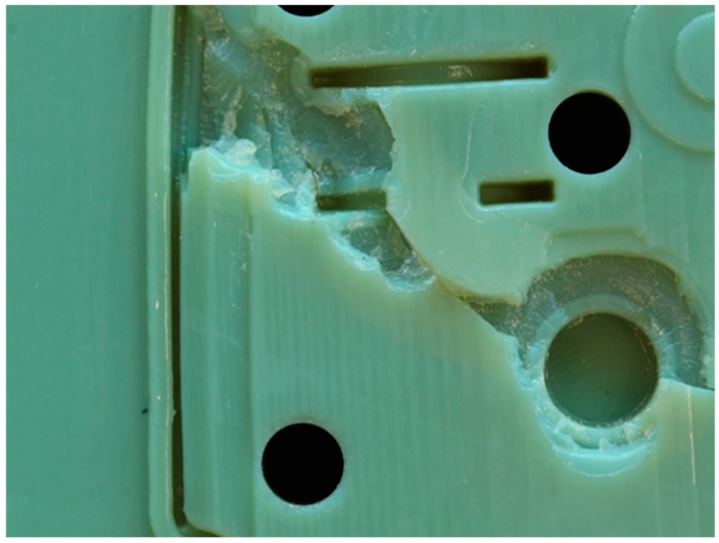
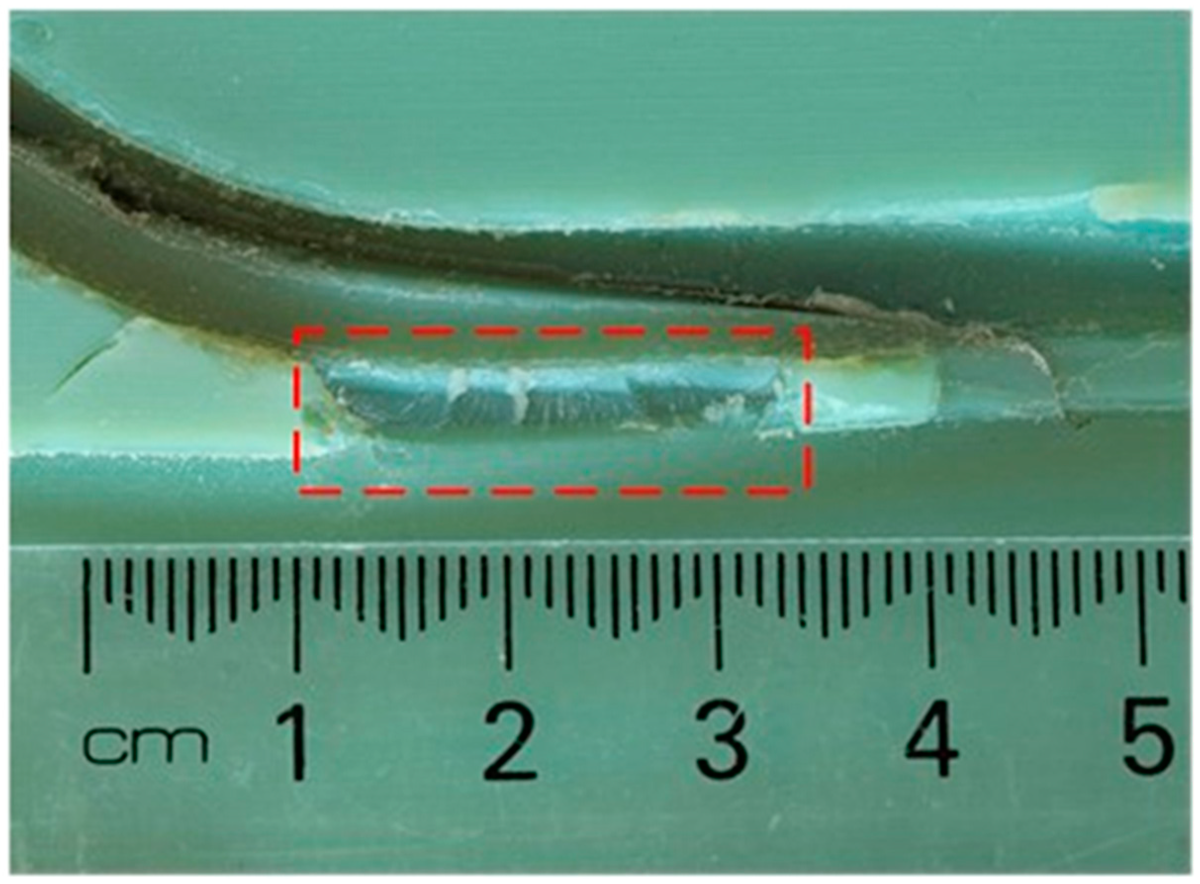
Once the mold was 95% filled, a second stage (hold) pressure was applied, to force excess melt into the cavity, to compensate for the shrinkage of the injected polymer. This second-stage pressure resulted in adhesion between the deteriorated surface of the PRT insert and the part. Avulsion failure was observed in case study 2 on the core insert; see
Figure 8 and
Figure 9. The central hole on the core insert was initially observed to be deteriorating, and as the cracks extended, the part was seen to be avulsing chunks of material from the insert during each shot.
The insert at this stage was at a higher temperature than the Tg of the tool. We infer that this causes the tool to lose its strength, and also when the part is ejected; hence, avulsion of the mold surface may occur. The term avulsion refers to the ripping and peeling of the surface material of a body. Our proposed explanation is that during the first few shots, surface damage occurs, which leads to surface cracks (micro-spallation). During subsequent shots, molten polymer enters these micro-cracks and enlarges them; as the cracks grow, more molten polymer is forced into the cracks before solidifying. During ejection, this solidified polymer causes layers of the mold to be torn off. Avulsion failure is a progressive rather than an abrupt failure mode.
3.3. Feature Damage (Stage 3—Fracture of Features)
3.3.1. Shear Failure
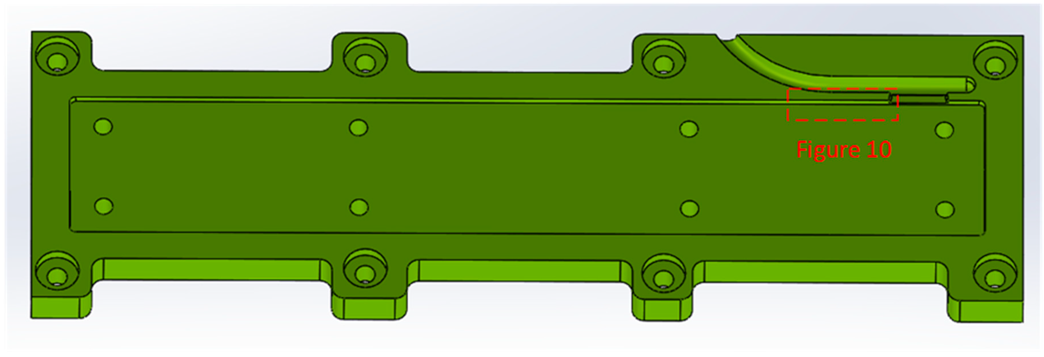
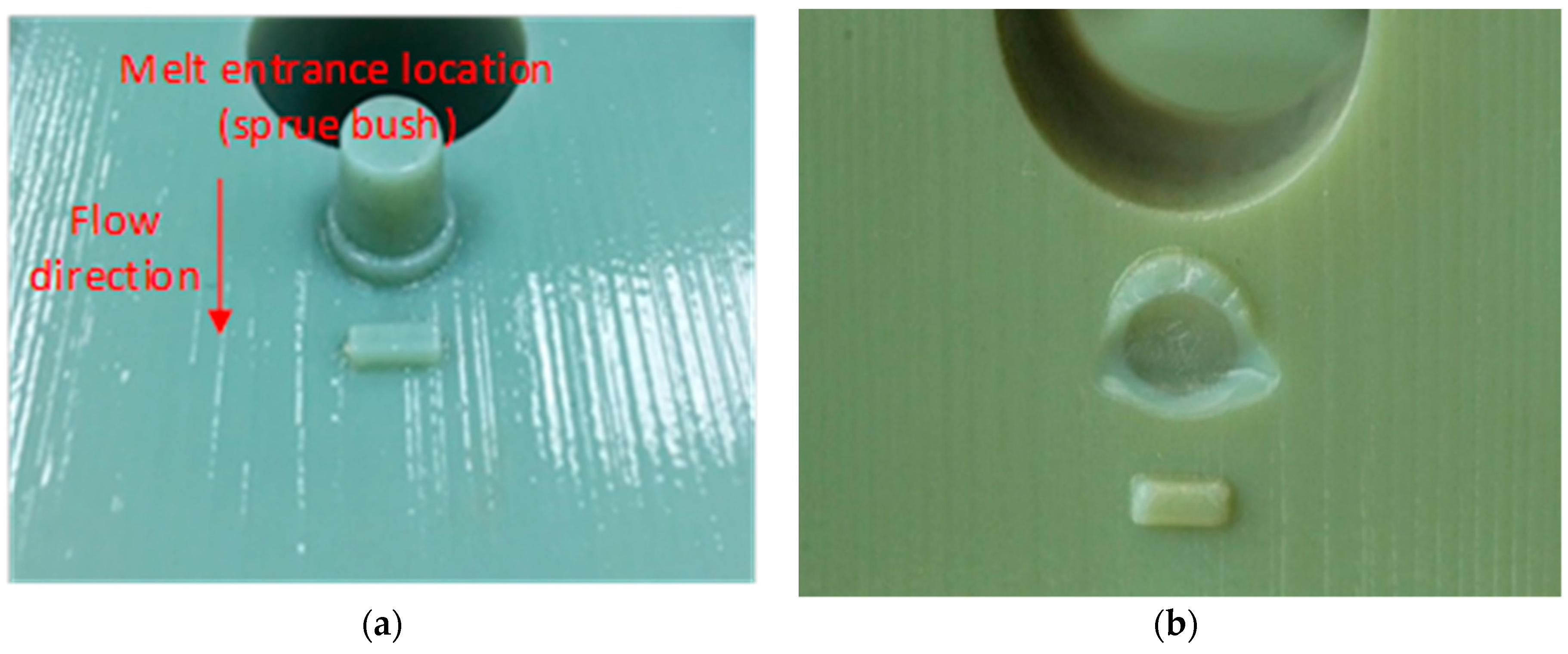
During the injection stage, the polymer melt is forced into the insert under pressure. The polymer melt while filling the cavity exerts a force on the mold features, such as walls, bosses, and ribs. This force is responsible for a stress which, if exceeds the ultimate tensile strength of the material at that temperature, may result in the failure of the feature. The injection pressure is highest during the start of the injection cycle, and gradually reduces; this means that the features of the insert that are the closest to the injection point (gate) are more susceptible to failure. Shear failure was observed during case study 1 on the runner wall of the PRT insert; see
Figure 10. The high melt pressure during the initial process parameter setup phase caused the wall to shear and cause a catastrophic failure of the mold. The wall of the runner sheared off on the first shot, but it did not completely break off from the mold surface; during the subsequent shots, the wall broke off the mold surface.
Figure 3 shows the wall of the runner that sheared off. This was classified as shear failure, due to the low aspect ratio (height/thickness) of the wall. This was a critical failure, as it was a runner wall, and we could not produce any more parts from the insert—it would be unsafe to try. We infer that shear failure may be a particular risk in areas with low aspect ratio thin walls that are close to the gate (melt entrance).
3.3.2. Bending Failure
A bending failure was observed in case 2; see
Figure 11. This feature on the tool was supposed to create a hole on the part, but the boss feature was broken off the tool after five shots, and all the parts molded after it had a thick section instead of a hole. Although this made the part functionally defective, it was not considered a critical failure, as it was still safe to operate the tool. The melt pressure was causing the boss to bend during the initial filling stage. This eventually led to a crack at the bottom surface, and failure of the boss in subsequent shots. The boss was situated directly 5 mm in front of the injection point; this meant that the boss was experiencing the highest pressure of all of the features on the tool.
The incoming polymer melt during the injection stage exerts a pressure on the front face of a feature, leading to a deflection; as the melt front reaches the back face of the feature, there is a reduced pressure difference between the back and front faces, and the deflection of the feature reduces. This cycle is repeated during each molding cycle, and may be responsible for the development of a crack, which may eventually lead to a complete failure of the PRT insert. Features with high aspect ratios (height/thickness) should in principle, be the most vulnerable to bending failure.
3.3.3. Edge Fractures
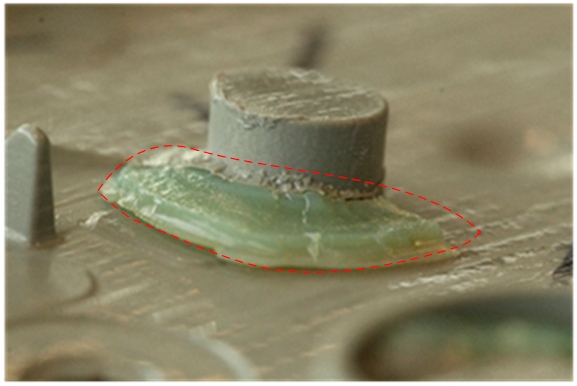
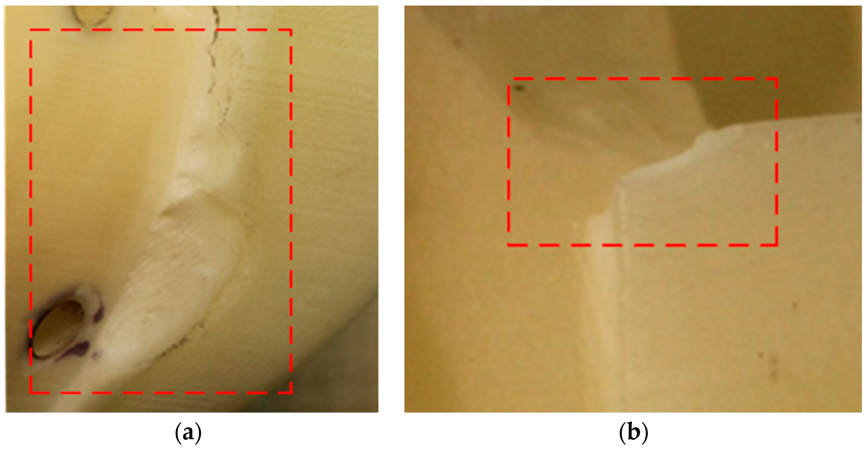
The edges of the PRT insert deteriorated with each shot, and small chips of the material were seen to be eroding from the edges; see
Figure 12. This was particularly worse near the areas of the runner (melt entrance) where the melt pressure was high; the edge deterioration was less on the edges at the end of the melt flow.
The other reason for the edge failure is the draft on the walls. During ejection, there is constant friction between the part and the mold walls. The mold during the ejection stage is above its Tg and has low yield strength. The part while ejecting starts to degrade the surface (erosion) during the early shots, and results in chipping when there is significant deterioration. An advanced version of the edge failure was observed in case study 3. During case study 1, edge failure was not considered as a significant failure, because it did not pose any safety issues, and it was not flashing. However, the PRT insert in case study 2 was only used for five shots, after which it failed via the shear failure mode. In case study 3 the tool survived the initial process parameter setup phase, and the edges deteriorated progressively from the ninth to the 13th shot. During the ejection of the 14th shot, a large shard of material was pulled out. After this shot, the tool was flashing, due to the failure of the edge that was on the parting line of the tool. Surface erosion was seen on all of the edges along the flow path, and chipping was only seen on edges that had no draft. At the end of the 19th shot, the fracture was about 5 mm wide, and this was the final failure on the tool.
3.4. Categorization of Failures
Based on the above case studies, and after examining the molds and sectioning the inserts in the cracked region, we identified a list of common failure modes. The main categories of failure were identified as: shear failure; bending failure; avulsion; surface deterioration; edge failure; surface scalding.
Table 5 summarizes the types of failure, the probable reasons and the common regions of occurrence for each type of failure. This table may be useful as a guide for part, tool, and process design.
4. Discussion
4.1. Towards a Theory of Failure
We propose that multiple failure mechanisms are operating: thermal degradation of the surface of the tool material (scalding); crack growth due to creep (surface deterioration); localized tensile failure of surface (avulsion); crack formation due to applied stresses on the tool features (bending and shear); crack growth due to the intrusion of pressurized molten material, with subsequent avulsion of tool material. The failure modes appear to influence each other, and be connected in cascade sequences.
Injection pressure, injection temperature, and mold temperature are identified as major factors that contribute to the failure mechanisms. The combined effect is a progressive failure that leads to catastrophic failure after a few molding cycles.
Three phases in the Failure Process.
The results have identified the types of locations where the failures initiate, and the appearance of the final failure. Generally, the progression shows three stages: crack initiation, crack growth, and structural failure.
First stage: Occurrence of surface damage (surface deterioration, scalding), which then results in a crack. The surface damage occurs due to the tool temperature, melt temperature, and shear heating. The latter is affected by the injection pressure.
Second stage: Crack growth (avulsion). Once a crack forms, its growth is rapid. A large extension of the crack was evident at each shot. In conventional applications of creep-fatigue, the crack is hidden inside the bulk of the material. However, in the case of IM, there is an additional mechanism that is highly deleterious. This is the combination of the intrusion of melt material into the crack, the solidification of that material, and the subsequent violent avulsion thereof at ejection. The ejection occurs at the opening of the tool, and is driven by ejector pins. Hence, there is another source of external loading on the features, other than injection pressure, that occurs at the end of each cycle. This process causes extensive damage to the cracked region, and this sets up the geometry for further damage at the next cycle.
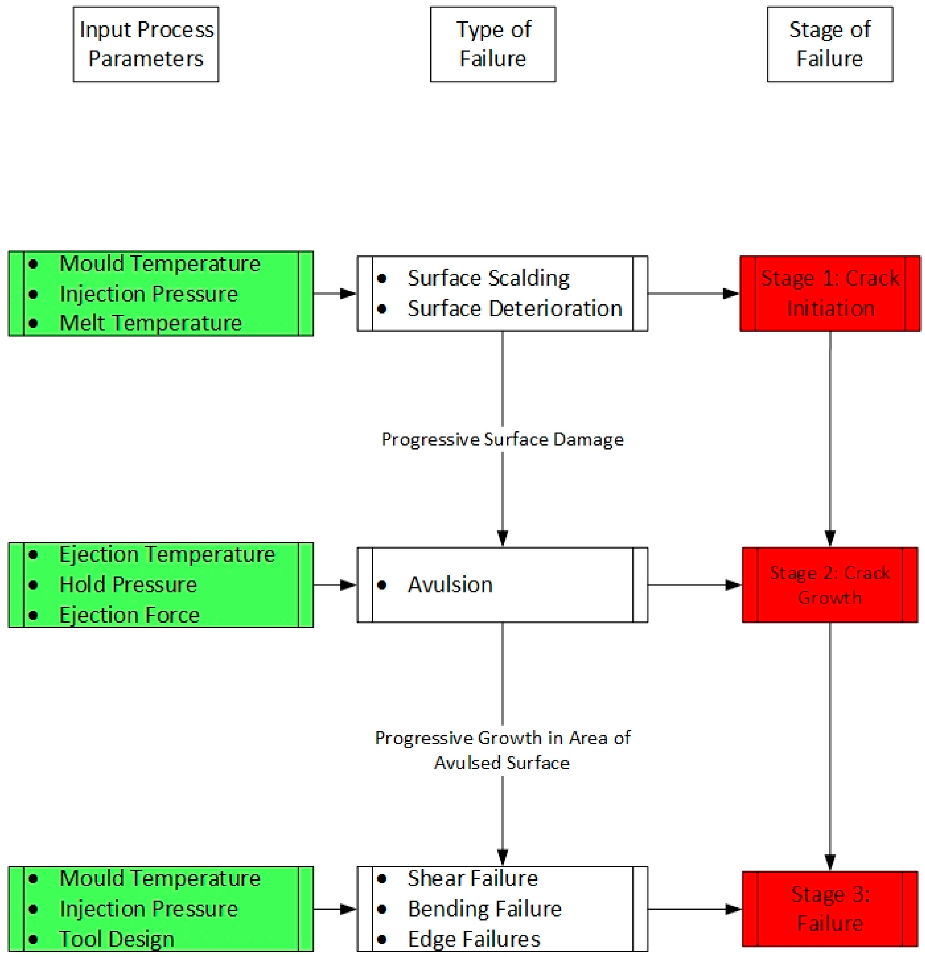
Third Stage: Rapid destruction of the features within the tool, and a catastrophic deterioration of the integrity of the features, and sometimes of the tool (shear and bending failure). This process is similar to the generally accepted creep-fatigue failure process, but is accelerated by the intrusion effect. We propose the following conceptual map of the failure process; see
Figure 13. The green color in the image represents the reason for failure and the red color represents the underlying failure mechanisms.
4.2. Implications for Practitioners
The main implication for tool designers is to avoid gating (melt entrance) near thin walls and raised features. This is because the injection pressure near the gate is the highest, and can cause shear and bending failure of these features. Tool designers could consider using flow simulation software to evaluate the pressure consequences of different gating locations. They could also identify the problematic areas so that molding technicians can monitor these locations after each shot.
4.3. Limitations of the Work
In this work we did not optimize gate location beforehand—instead, the location was determined primarily from the usual perspective of design convenience, rather than tool life. It is possible that a different gate location might have reduced some of the observed failures. In this study, we used only the recommended settings from the machine manufacturers (3D Systems and Stratasys). We did not experiment with changing the settings for layer thickness, nozzle speed, or infill density. It is possible that experimenting with different print settings and different post processing routes could alter the failure mechanisms. The failure analysis shown here is only relevant for 3D-printed tools. Such tools are increasingly being used in industry, but generally for molding benign materials (low melt temperatures) and not the more demanding materials that are shown here.
4.4. Implications for Future Research
The surface delamination (avulsion) is an interesting failure that starts below the surface of the PRT insert. Further research could be directed at better understanding this process, and how to avoid or suppress it for as long as possible. This is important because the inserts could still be safely used when small features were breaking off, but they became unusable only after avulsion occurred. Large-scale avulsion quickly degenerates into catastrophic failure of the tool. Hence, a better understanding the causes seems to be an important future direction of research. The effect is anticipated to be material-specific.
A possible future line of enquiry could be to use a design of experiments (DoE) approach to determine which variables contribute most to the failure process, and how they relate. This is likely to be an expensive process, given the destructive nature of the testing. In the current work, we have used real parts, but this would be disfavored for a DoE approach. Instead it may be preferable to use small parts with representative features.
Print settings and post-processing operations such as post-curing, polishing, and cleaning methods may also affect the failure processes, and hence, the life of the PRT inserts. Hence, a possible further line of enquiry could be to study the effect of these parameters.
Another possible research direction could be the microscopic analysis of fracture surfaces. This might help identify the relative contributions of creep vs fatigue vs thermal degradation effects at various stages of the failure. Our observations are that the white Visijet material is difficult to observe under optical microscopy, due to its poor contrast, but other colors or microscopy techniques may be more successful.
5. Conclusions
Case study investigations of PRT inserts used for IM suggest that the main failure modes are: shear failure; bending failure; avulsion; surface deterioration; edge failure; surface scalding. We have proposed a crack propagation theory, and we provide a conceptual map relating these failure modes to the root causes. The failure modes influence each other, and they may be connected in cascade sequences. Several suggestions are given for prolonging the tool life, via design practices and setting parameters. The latter includes the process of setting up the molding parameters. The original contributions of this work are the identification of failure modes, and the relationship with root causes and the proposed crack propagation theory.
This paper identifies the critical process parameters, and their effects on different areas of the PRT insert. The conceptual map for failures presented indicates a gradual progressive failure of the PRT insert, from initial surface quality defects, through to catastrophic feature failure. Mold temperature was a critical parameter, since it affected all areas of the tool, and contributed to multiple failure modes. Injection pressure was only significant in certain areas of the tool (injection pressure had little to no effect on failure of PRT inserts at the end of flow, and had the highest effect on features closest to the start of the flow path). Tool design was a factor in areas of the tool that had tall free-standing features.
The wider purpose of this work was to study the feasibility of: (a) using PRT inserts to mold resins with melt temperatures above 250 °C; (b) determining the size of the parts that can be successfully molded by using a PRT insert; (c) determining the variety of features that can be safely molded by using a PRT insert; (d) determining the number of parts that can be molded before failure, and (e) the quality control of the molded parts. In this study, we were able to answer point (a): it is feasible to mold resins with high melting temperatures of up to 350 °C, and we can expect about 14 parts from the mold before failure, for the cases under examination. Consequently, it is possible to obtain a limited run of injection molded parts from an inexpensive 3D-printed tool. This is important, because the mechanical behavior of an injected molded part can be very different to a 3D-printed part. Nonetheless further research is required to address the other variables (b) to (e), and to increase the part count.
Author Contributions
This work was conducted by A.B., and supervised by D.P., D.C., and D.S. The ideas for failure modes were developed by A.B. and D.P. All authors contributed to the writing of the paper.
Funding
This research was funded by Callaghan Innovation, grant number TALB 1501/PROP-47676-FELLOW TALBOT.
Acknowledgments
We thank Talbot Technologies Ltd. for the opportunity to pursue this research. Special thanks to Steve W, Steve O, Lance F, and Ben A at Talbot Technologies for continued support through the project.
Conflicts of Interest
The authors declare no financial conflict of interest in this project. The funding agency and industry partners did not control the research, nor influence the content of the paper.
References
- Weber, A. 3D printing goes from prototyping to production. Assembly 2018, 61, 58–63. [Google Scholar]
- Annacchino, M.A. The Pursuit of New Product Development: The Business Development Process; Butterworth-Heinemann: Amsterdam, The Netherland; Boston, MA, USA, 2007. [Google Scholar]
- Brethauer, D.M. New Product Development and Delivery: Ensuring Successful Products through Integrated Process Management; AMACOM: New York, NY, USA, 2002. [Google Scholar]
- Otto, K.N.; Wood, K.L. Product Design: Techniques in Reverse Engineering and New Product Development; Pearson Custom Pub.: Boston, MA, USA, 2006. [Google Scholar]
- Rosato, D.V.; Rosato, D.V. Injection Molding Handbook: The Complete Molding Operation Technology, Performance, Economics, 2nd ed.; Chapman & Hall: New York, NY, USA, 1995. [Google Scholar]
- Kazmer, D.O. Mold Cost Estimation. In Injection Mold Design Engineering; Hanser: Cincinnati, OH, USA, 2007; pp. 37–66. [Google Scholar]
- Goodship, V. Practical Guide to Injection Moulding; Rapra Technology: Shawbury, UK, 2004. [Google Scholar]
- Kazmer, D.O. Introduction. In Injection Mold Design Engineering; Hanser: Cincinnati, OH, USA, 2007; pp. 1–15. [Google Scholar] [CrossRef]
- Yarlagadda, P.K.D.V.; Wee, L.K. Design, development and evaluation of 3D mold inserts using a rapid prototyping technique and powder-sintering process. Int. J. Prod. Res. 2006, 44, 919–938. [Google Scholar] [CrossRef]
- Wagner, S.M.; Walton, R.O. Additive manufacturing’s impact and future in the aviation industry. Prod. Plan. Control 2016, 27, 1124–1130. [Google Scholar] [CrossRef]
- Ong, H.S.; Chua, C.K.; Cheah, C.M. Rapid Moulding Using Epoxy Tooling Resin. Int. J. Adv. Manuf. Technol. 2002, 20, 368–374. [Google Scholar] [CrossRef]
- Gardan, J. Additive manufacturing technologies: State of the art and trends. Int. J. Prod. Res. 2016, 54, 3118–3132. [Google Scholar] [CrossRef]
- Noble, J.; Walczak, K.; Dornfeld, D. Rapid Tooling Injection Molded Prototypes: A Case Study in Artificial Photosynthesis Technology. Procedia CIRP 2014, 14, 251–256. [Google Scholar] [CrossRef]
- Upcraft, S.; Fletcher, R. The rapid prototyping technologies. Assem. Autom. 2003, 23, 318–330. [Google Scholar] [CrossRef]
- Chua, C.K.; Leong, K.F.; Liu, Z.H. Rapid Tooling in Manufacturing. In Handbook of Manufacturing Engineering and Technology; Nee, A.Y.C., Ed.; Springer: London, UK, 2015; pp. 2525–2549. [Google Scholar]
- Hopkinson, N.; Dickens, P. Predicting stereolithography injection mould tool behaviour using models to predict ejection force and tool strength. Int. J. Prod. Res. 2000, 38, 3747–3757. [Google Scholar] [CrossRef]
- Sa Ribeiro, A., Jr.; Hopkinson, N.; Ahrens, C.H. Thermal effects on stereolithography tools during injection moulding. Rapid Prototyp. J. 2004, 10, 4. [Google Scholar] [CrossRef]
- Fernandes, A.D.C.; De Souza, A.F.; Howarth, J.L.L. Mechanical and dimensional characterisation of polypropylene injection moulded parts in epoxy resin/aluminium inserts for rapid tooling. Int. J. Mater. Prod. Technol. 2016, 52, 15. [Google Scholar] [CrossRef]
- Dos Santos, W.N.; De Sousa, J.A.; Gregorio, R., Jr. Thermal conductivity behaviour of polymers around glass transition and crystalline melting temperatures. Polym. Test. 2013, 32, 987–994. [Google Scholar] [CrossRef]
- Rahmati, S.; Dickens, P. Stereolithography for injection mould tooling. Rapid Prototyp. J. 1997, 3, 53–60. [Google Scholar] [CrossRef]
- Park, H.; Cha, B.; Cho, S.; Kim, D.; Choi, J.H.; Pyo, B.-G.; Rhee, B. A study on the estimation of plastic deformation of metal insert parts in multi-cavity injection molding by injection-structural coupled analysis. Int. J. Adv. Manuf. Technol. 2016, 83, 2057–2069. [Google Scholar] [CrossRef]
- Rahmati, S.; Dickens, P. Rapid tooling analysis of Stereolithography injection mould tooling. Int. J. Mach. Tools Manuf. 2007, 47, 740–747. [Google Scholar] [CrossRef]
- Harris, R.; Hopkinson, N.; Newlyn, H.; Hague, R.; Dickens, P. Layer thickness and draft angle selection for stereolithography injection mould tooling. Int. J. Prod. Res. 2002, 40, 719–729. [Google Scholar] [CrossRef]
- Harris, R.A.; Newlyn, H.A.; Dickens, P.M. Selection of mould design variables in direct stereolithography injection mould tooling. Proc. Inst. Mech. Eng. 2002, 216, 499–505. [Google Scholar] [CrossRef]
- Accura Bluestone. Available online: https://www.3dsystems.com/materials/accura-bluestone (accessed on 25 June 2018).
- DSM Perform. Available online: https://www.dsm.com/solutions/additive-manufacturing/en_US/products/for-stereolithography/somos-perform.html (accessed on 25 June 2017).
- Digital ABS Plus. Available online: http://www.stratasys.com/materials/search/digital-abs-plus (accessed on 25 June 2017).
- Rajaguru, J.C.; Duke, M.; Au, C. Investigation of electroless nickel plating on rapid prototyping material of acrylic resin. Rapid Prototyp. J. 2016, 22, 162–169. [Google Scholar] [CrossRef]
- Rajaguru, J.; Duke, M.; Au, C. Development of rapid tooling by rapid prototyping technology and electroless nickel plating for low-volume production of plastic parts. Int. J. Adv. Manuf. Technol. 2015, 78, 31–40. [Google Scholar] [CrossRef]
- Belter, J.T.; Dollar, A.M. Strengthening of 3D Printed Fused Deposition Manufactured Parts Using the Fill Compositing Technique. PLoS ONE 2015, 10, e0122915. [Google Scholar] [CrossRef] [PubMed]
Figure 1.
Stages of a new product development (NPD) process from an engineering perspective.
Figure 1.
Stages of a new product development (NPD) process from an engineering perspective.
Figure 2.
Process workflow.
Figure 2.
Process workflow.
Figure 3.
Solid model of the cavity insert used for printing.
Figure 3.
Solid model of the cavity insert used for printing.
Figure 4.
Core and cavity insert.
Figure 4.
Core and cavity insert.
Figure 5.
(a) Core insert for case study 3, fitted inside a master unit die. (b) Cavity insert for case study 3, fitted inside a master unit die. The tool outer diameter is 55 mm.
Figure 5.
(a) Core insert for case study 3, fitted inside a master unit die. (b) Cavity insert for case study 3, fitted inside a master unit die. The tool outer diameter is 55 mm.
Figure 6.
(a) Tool material eroded and deposited on the seventh shot from the tool. (b) Protrusions on the eighth part, due to surface deterioration of the tool in the same vicinity. (c) Magnified image of the area of the eroded tool surface.
Figure 6.
(a) Tool material eroded and deposited on the seventh shot from the tool. (b) Protrusions on the eighth part, due to surface deterioration of the tool in the same vicinity. (c) Magnified image of the area of the eroded tool surface.
Figure 7.
(a) Surface scalding patch attached to the part in shot 12. (b) Protrusion mold in a similar area, shape, and size because of the surface scalding, in shot 13. The scalded tool material has adhered to the part in (a), and hence, the tool has lost material.
Figure 7.
(a) Surface scalding patch attached to the part in shot 12. (b) Protrusion mold in a similar area, shape, and size because of the surface scalding, in shot 13. The scalded tool material has adhered to the part in (a), and hence, the tool has lost material.
Figure 8.
Avulsion failure region on the PRT insert from case study 2. This failure mode is characterized by progressive peeling of the substrate material. The image shows the catastrophic end-state of the process.
Figure 8.
Avulsion failure region on the PRT insert from case study 2. This failure mode is characterized by progressive peeling of the substrate material. The image shows the catastrophic end-state of the process.
Figure 9.
Molded part showing peeled off tool material from the top surface. This occurred during the ejection of the part. (Area highlighted is the tool material pulled out).
Figure 9.
Molded part showing peeled off tool material from the top surface. This occurred during the ejection of the part. (Area highlighted is the tool material pulled out).
Figure 10.
Shear failure of the runner wall (boxed area), due to high injection pressure. See
Figure 3 for the location on the tool.
Figure 10.
Shear failure of the runner wall (boxed area), due to high injection pressure. See
Figure 3 for the location on the tool.
Figure 11.
(
a) Boss feature before molding. (
b) Bending failure of the boss feature due to high injection pressure. See
Figure 4 for the location on the tool.
Figure 11.
(
a) Boss feature before molding. (
b) Bending failure of the boss feature due to high injection pressure. See
Figure 4 for the location on the tool.
Figure 12.
(
a) Chipped edge of the tool caused during the ejection of the part. (
b) Chipped corner of the tool due to injection pressure. See
Figure 5 for the location on the tool.
Figure 12.
(
a) Chipped edge of the tool caused during the ejection of the part. (
b) Chipped corner of the tool due to injection pressure. See
Figure 5 for the location on the tool.
Figure 13.
A conceptual map of the interaction between the root causes and the failure modes.
Figure 13.
A conceptual map of the interaction between the root causes and the failure modes.
Table 1.
The type of part, and the reason for each of the case study.
Table 1.
The type of part, and the reason for each of the case study.
| Case Study | Type of Part | Reason for Study |
|---|
| Case Study 1 | Standard Flame Test Specimen | Feasibility Testing |
| Case Study 2 | Electronic Enclosure | Understanding Failures |
| Case Study 3 | Aircraft Interior Part | Improving Tool Life |
Table 2.
Process parameters recommended vs used, for case study 1.
Table 2.
Process parameters recommended vs used, for case study 1.
| Parameter | Value |
|---|
| Resin Manufacturer | Sabic Innovative Plastics |
| Resin Name | Lexan 943-A |
| Resin Type | Polycarbonate/Amorphous |
| Mold Temperature | 80 °C |
| Melt Temperature | 310 °C |
| Maximum Injection Pressure Set | 180 MPa |
| Maximum Pressure Used | 146.6 MPa |
| Fill Time | 3.2 s |
| Switchover Point | 95% by volume |
| Highest Temperature of the Melt | 289 °C |
| Cooling Time | 55 s |
| Mold Open Time | Initially 20 s, was subsequently kept open until the mold temperature reduced to 80 °C |
Table 3.
Process parameters recommended vs used for case study 2.
Table 3.
Process parameters recommended vs used for case study 2.
| Parameter | Recommended Value | Actual Value Used |
|---|
| Resin Manufacturer | Sabic Innovative Plastics | Sabic Innovative Plastics |
| Resin Name | Lexan 943-A | Lexan 943-A |
| Resin Type | Polycarbonate/Amorphous | Polycarbonate/Amorphous |
| Mold Temperature | 105 °C | 45 °C |
| Melt Temperature | 285 °C | 305 °C |
| Maximum Injection Pressure Set | 180 MPa | 50 MPa |
| Maximum Pressure Used | N/A | 41 MPa |
| Fill Time | 0.87 s | 0.55 s |
| Switchover Point | 95% by volume | 90% by volume |
| Highest Temperature of the melt | 289 °C | 311 °C |
| Cooling Time | 15 s | 45 s |
| Mold Open Time | 30 s | Mold kept open until mold reduced to the target temperature of 45 °C after every cycle |
Table 4.
Process parameters recommended vs used, for case study 3.
Table 4.
Process parameters recommended vs used, for case study 3.
| Parameter | Recommended Value | Actual Value Used |
|---|
| Resin Manufacturer | Sabic Innovative Plastics | Sabic Innovative Plastics |
| Resin Name | Lexan 943-A | Lexan 943-A |
| Resin Type | Polycarbonate/Amorphous | Polycarbonate/Amorphous |
| Mold Temperature | 105 °C | 45 °C |
| Melt Temperature | 285 °C | 285 °C |
| Maximum Pressure Set | 180 MPa | 70 MPa |
| Maximum Pressure Used | N/A | 62 MPa |
| Fill Time | 0.5 s | 1.2 s |
| Switchover Point | 95% | 90% |
| Highest Temperature of the Melt | 315 °C | 300 °C |
| Cooling Time | 10 s | 25 s |
| Mold Open Time | 5 s | Until the mold temperature after every shot is reduced to 45 °C. |
Table 5.
Categorization of failures.
Table 5.
Categorization of failures.
| | Failure Modes | | Type of Failure | Observed Regions | Possible Root Causes | Shot Number during Which Failure Was First Detected |
|---|
| 1 | Surface Failure
(Crack Formation) | 1.1 | Surface Deterioration | All over the surface, higher at the melt entrance | Low melt temperature, high mold temperature | 7 |
| | 1.2 | Surface Scalding | Regions around the gate and periphery of the tool | Shear heating, high tool temperature, lack of air venting | 13 |
| 2 | Avulsion
(Crack Growth) | 2 | Avulsion | Directly in front of the gate and close to features | Ejection force, long cooling cycle, draft angle | 14 |
| 3 | Feature Failure
(Fracture) | 3.1 | Shear Failure | Thin walls and raised features (low aspect ratio) | High injection pressure, high tool temperature, gate location | 3 |
| | 3.2 | Bending Failure | Raised features, high aspect ratio | High injection pressure, high tool temperature, gate location | 5 |
| | 3.3 | Edge Failure | Edges closer to the gate | Low draft angle, stress concentration, gate location | 13 |
© 2019 by the authors. Licensee MDPI, Basel, Switzerland. This article is an open access article distributed under the terms and conditions of the Creative Commons Attribution (CC BY) license (http://creativecommons.org/licenses/by/4.0/).


