Article

A Numerical Study of Stress Distribution and Fracture Development above a Protective Coal Seam in Longwall Mining

1
International Engineering Company of China Coal Technology and Engineering Group, Beijing 100013, China
2
College of Resources and Safety Engineering, China University of Mining and Technology (Beijing), Beijing 100083, China
3
Department of Mining and Mineral Resources Engineering, Southern Illinois University, Carbondale, IL 62901, USA
4
Department of Chemical and Petroleum Engineering, University of Calgary, Calgary, AB T2N 1N4, Canada
*
Author to whom correspondence should be addressed.
Processes 2018, 6(9), 146; https://doi.org/10.3390/pr6090146
Submission received: 7 August 2018 / Revised: 16 August 2018 / Accepted: 17 August 2018 / Published: 1 September 2018
(This article belongs to the Special Issue Fluid Flow in Fractured Porous Media)

Abstract

:
Coal and gas outbursts are serious safety concerns in the Chinese coal industry. Mining of the upper or lower protective coal seams has been widely used to minimize this problem. This paper presents new findings from longwall mining-induced fractures, stress distribution changes in roof strata, strata movement and gas flow dynamics after the lower protective coal seam is extracted in a deep underground coal mine in Jincheng, China. Two Flac3D models with varying gob loading characteristics as a function of face advance were analyzed to assess the effect of gob behavior on stress relief in the protected coal seam. The gob behavior in the models is incorporated by applying variable force to the floor and roof behind the longwall face to simulate gob loading characteristics in the field. The influence of mining height on the stress-relief in protected coal seam is also incorporated. The stress relief coefficient and relief angle were introduced as two essential parameters to evaluate the stress relief effect in different regions of protected coal seam. The results showed that the rock mass above the protective coal seam can be divided into five zones in the horizontal direction, i.e. pre-mining zone, compression zone, expansion zone, recovery zone and re-compacted zone. The volume expansion or the dilation zone with high gas concentration is the best location to drill boreholes for gas drainage in both the protected coal seam and the protective coal seam. The research results are helpful to understand the gas flow mechanism around the coal seam and guide industry people to optimize borehole layouts in order to eliminate the coal and gas outburst hazard. The gas drainage programs are provided in the final section.

1. Introduction and Background

Coal as a major energy source accounted for 62% of Chinese energy consumption in 2016. It has remained the most important fuel in China’s energy mix for the last few decades [1]. In recent years, the safety situation of Chinese coal industry has improved, but gas and coal outbursts still seriously threaten coal mine safety due to the fact that the mining depth increases at a rate of 30–50 m/year in China [2]. According to statistical data, the death toll of coal miners reached up to 608 in 76 gas accidents from 2012 to 2015 [3]. Additional effective measures and research, hence, should be carried out to reduce and avoid gas disasters in China.
Stress redistribution and rock mass fracture are two dominant factors influencing rock mass permeability [4,5,6]. Coal and rock mass permeability increases due to stress relief and mining induced fracturing [5]. It has been reported by several researchers at both laboratory and field scales [1,2,3,4,7]. A great deal of previous work showed that changes in coal permeability is induced by changes in the confining stress, and found an exponential relationship between permeability and stress [
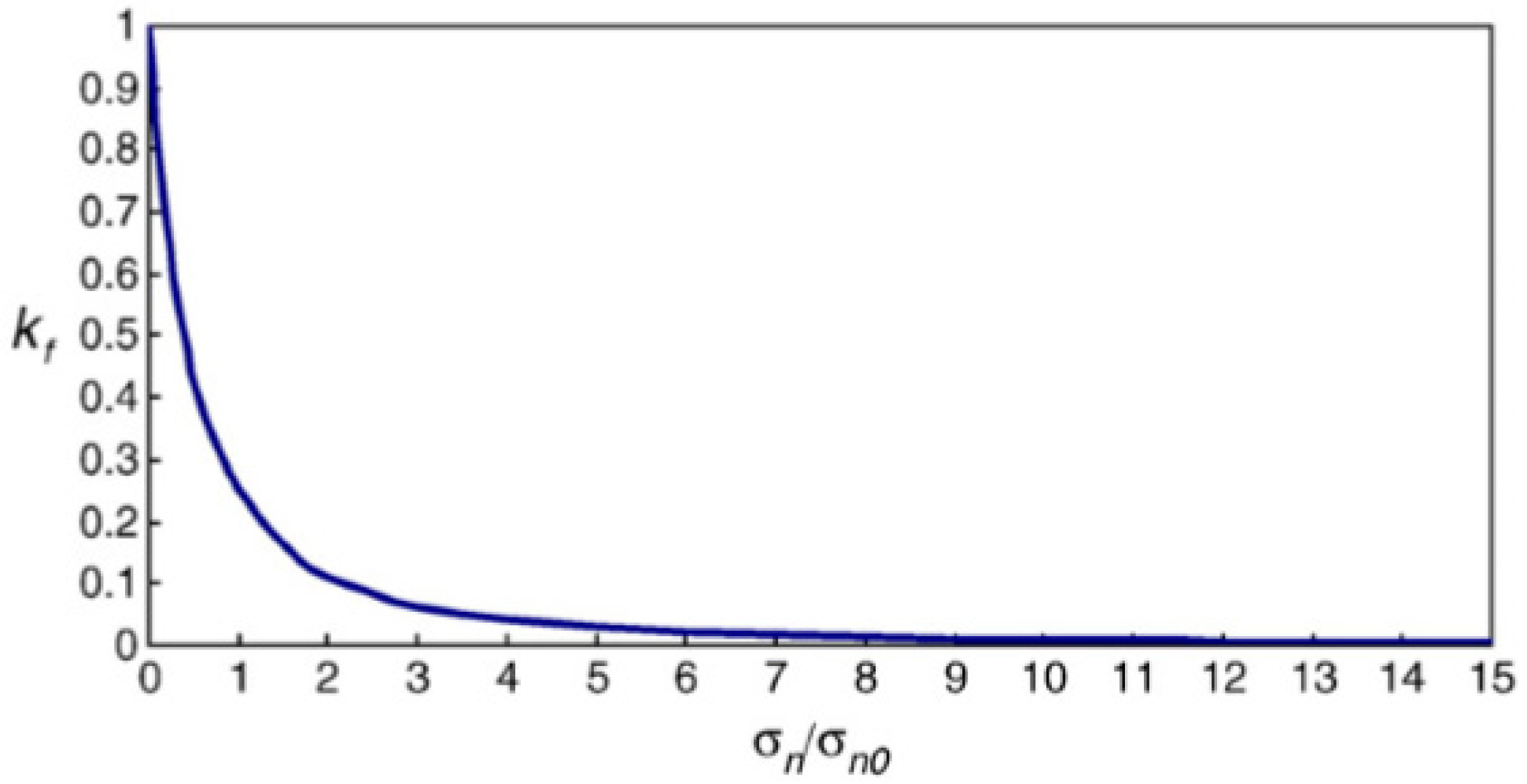
8]. A confining stress change of 10 MPa may result in changes in permeability with approximately one order of magnitude. Yang et al. [9] provides a visible relationship between dimensionless permeability and multiples of the initial normal stress (see Figure 1, σ n 0 is initial normal stress, σ n / σ n 0 is multiples of the initial normal stress, and k f 
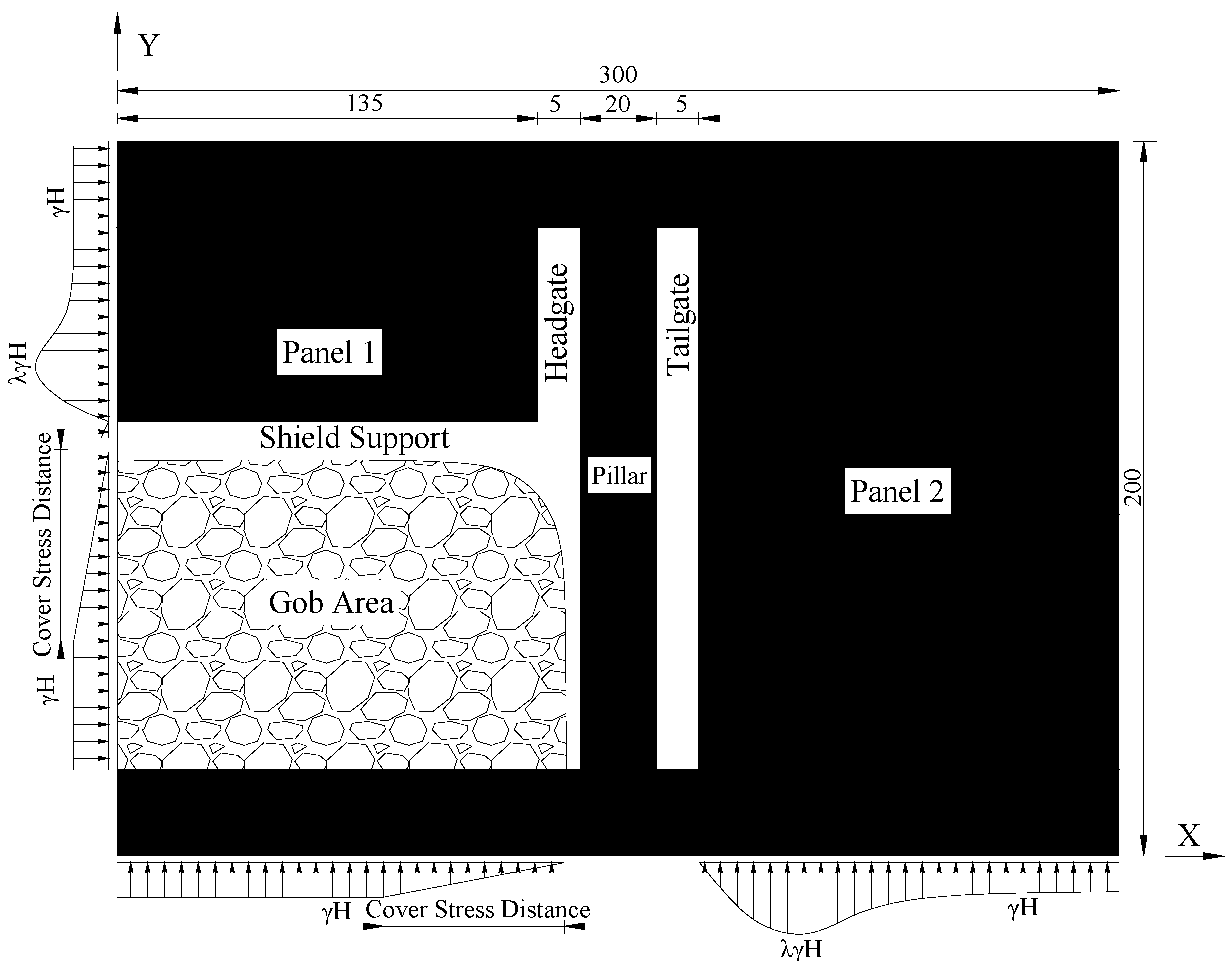
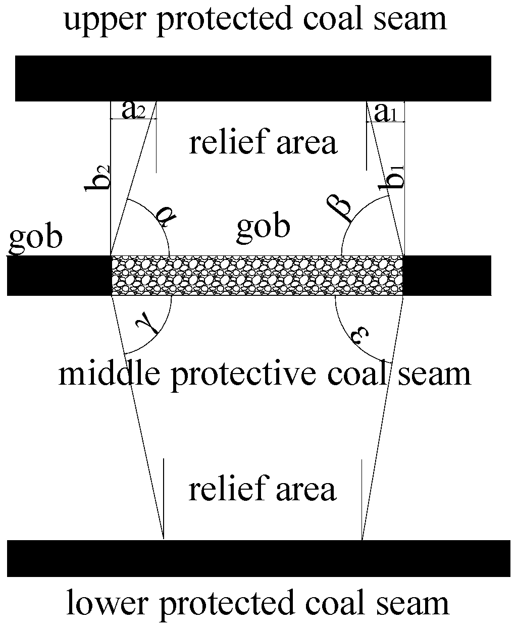
is dimensionless permeability). It shows permeability decreases with increasing normal stress. Therefore, the mining of the protective coal seam is wildly used in the multiple coal seams in China (Figure 2). As shown in Figure 2, the coal seam which overlies the target seam is designated as the upper protective seam, whereas the underlying coal layer is called the lower protective seam. Extraction of a protective seam results in redistribution and relieving of some of the stress around underlying or overlying rock mass, thereby establishing new stress equilibrium [10]. Reestablishment of a new stress state will inevitably lead to the changes of structure and properties of rock masses, which will eventually promote the desorption rate of gas from coal matrix and considerably increase permeability in the target coal seam or strata with high gas content.

2. Objective of Research

Stress relief coefficient and pressure relief angles are introduced by authors of this paper to evaluate the influence of lower protective excavation on its upper protected coal seam. The location of the protective layer, the horizontal butt entry and the mining height are key factors affecting the safety of protected coal seam mining [11]. This is because the relief area in the protected coal seam depends on a variety of parameters such as: The thickness and strength of the strata between the protected coal seam and the protective coal seam, the mining thickness, gob loading behavior, face advance rate, panel width, and pillar width of the extracted protective coal seam [11]. All of these factors should be taken into consideration to insure the safety of mining and the protected coal seam. In this paper, the mining height and gob behavior characteristics of protective coal seam are chosen as the two main factors affecting the results from protected coal seam excavation. As the effect of these two factors on the safety of mining the protected coal seam is still not clear. Therefore, an in-depth investigation on these two factors is necessitated in order to acquire the relief area in the protected coal seam and insure engineering safety. The final goal of this paper is to determine the stress relief coefficient and pressure relief angles along the strike and incline of the protective coal seam in order to locate the protection region (which is used for drilling boreholes) in the protected coal seam.
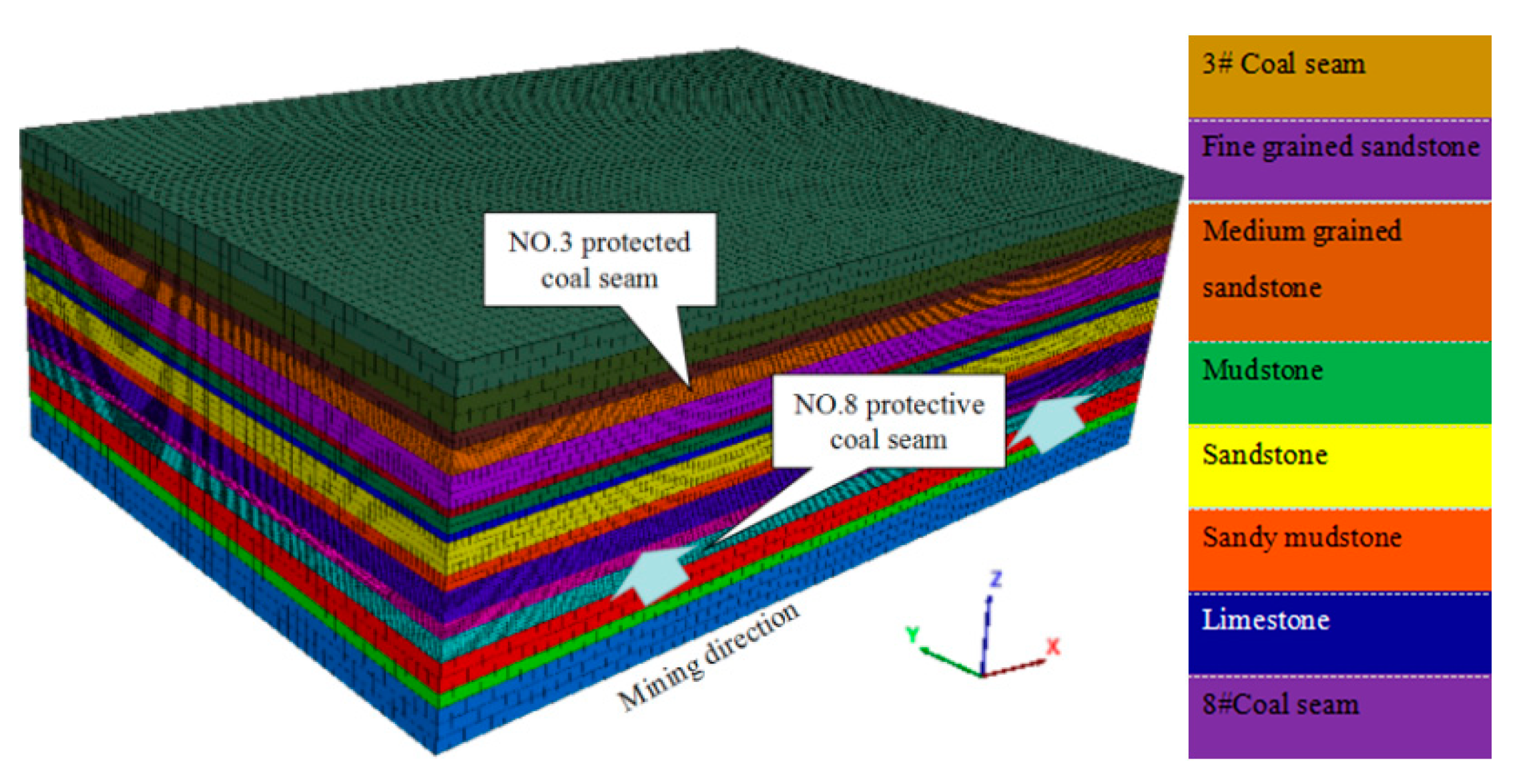
In this paper, authors attempt to develop a 3D model of two adjacent longwall faces in a physically realistic way with a consideration of gob loading behavior behind the face to improve understanding of stress distribution and stress relief not only around the protective coal seam but also in the protected coal seam after the excavation of protective coal seam (Figure 3). The stress distribution in the gob depends on mining depth, mining speed, excavation height, bulking factor and compressive strength. Since increasing the mining speed may delay the time for the stress recovery in the gob, it is worthwhile to do some research with a consideration of different gob loading behaviors behind the face. The longwall mining method has been widely used around the world in recent years because of its most important advantage of high efficiency [12]. A mine in Shanxi province (China) with longwall mining method is chosen for the research in this paper.

3. Literature Review on Gob Behaviors in Longwall Mining

Numerical modeling of protective coal seam mining’s influence on the protected coal seam has been extensively performed in the previous research [1,11]. However, gob loading characteristics have been widely ignored in their models. The authors believe that incorporating the gob loading characteristics into the model is essential for obtaining meaningful and realistic results. This is because the waste in the gob area can transfer the load from overburden to floor after the excavation of the coal seam. Ignoring load carried by the gob material will tend to increase stress concentrations in the face area and cause different stress distribution around excavation.
As the gob is inaccessible and direct measurements cannot be easily taken, it is very difficult to determine rock mass properties and stress distribution in the gob. A few techniques and research had been used and reported by previous researchers [13,14,15,16]. 
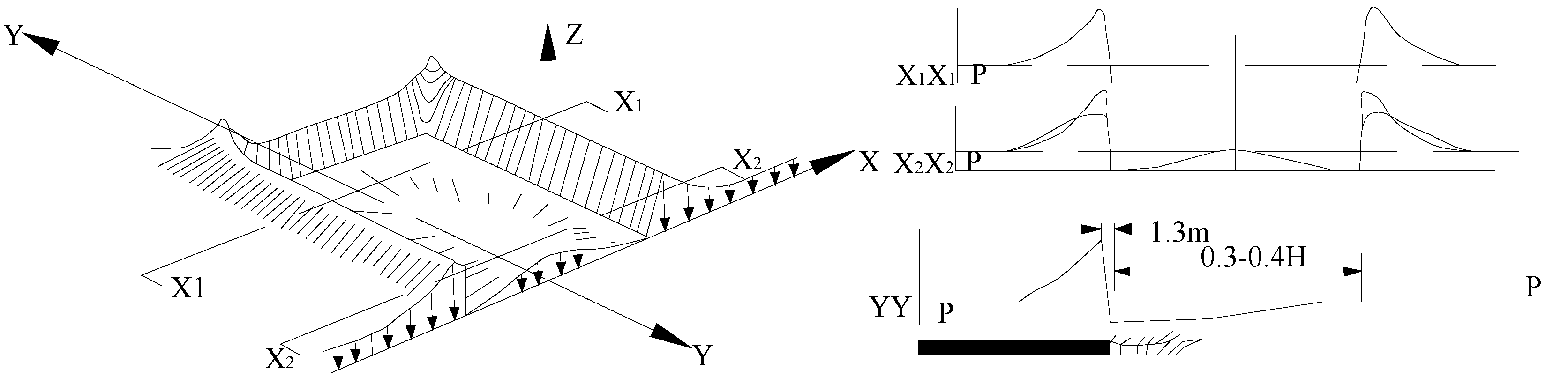
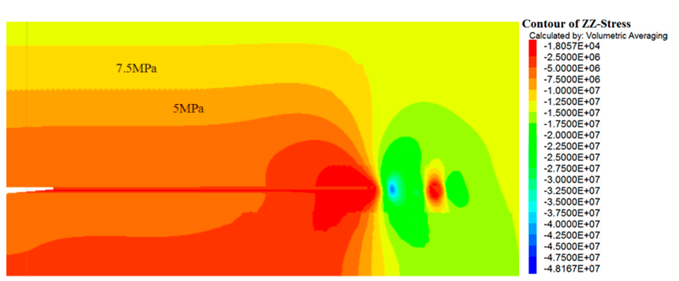
Figure 4 shows the strata pressure redistribution in the plane view of the seam around a longwall face after extraction. It shows that the abutment stress in coal ribs gradually recovers to the original stress state with the increasing distance from the rib-edge. The loading in the waste area gradually starts to pick up the overburden loading, and recovers its original stress at a distance from the face after the gob material can take the load from the overburden. Peng et al. [13] studied the supporting role of the gob material by performing three-dimensional element analysis. They divided the gob into three different zones: Loosely packed zone, packed zone, and well packed zone. The side and front abutment stresses will decrease considerably because of the support offered by the compacted gob. Whittaker [14] claimed that the cover pressure re-establishment distance is 0.3–0.4 times the coal seam depth (H) from the solid abutment (Figure 4). Wilson et al. [15] found that the vertical stress in the gob changes linearly, increasing from 0 at the rib to the original stress at a distance of 0.2–0.3 times the overburden depth. Whittaker and Singh [16] assumed that the gob began to take the load at a distance of 45 m from the face, and whether the gob can recover its original stress only depended on the width of the panel. Campoli et al. [17] investigated the longwall gob behavior in No. 3 coal seam of Pocahontas by field measurements under varying sets of geological conditions, and they found that the stress recovery distance in the gob was approximately 0.2 times of coal seam depth (360 m).
Modeling of Longwall mining with consideration of gob behaviors has also been documented in previous studies [18,19,20]. In these studies, the “double yield” elements were incorporated in their simulation model and the gob was regarded as a strain-hardening material. The stress-strain response of gob material was obtained through uniaxial compression tests and displacement measurements in a laboratory test [17]. Li et al. [18] evaluated the stress distribution in the yield pillar and the other rib of the entry in order to find the principle for yield pillar design by Flac3D numerical modeling. Esterhuizen et al. [19] examined the interaction between the surrounding rock mass and typical pillar systems for different geological conditions at various spans and depths of cover by establishing Flac2D numerical models. A method was proposed by H. Yavuz [20] to estimate the pressure distribution in the gob of flat-lying longwall panels and cover pressure distance, and this method was verified with curves obtained through numerical models. However, all these numerical longwall models with the gob behaviors were about pillar design and stability of entries, but not for the protective coal seam mining.
Generally, gob modeling can follow two approaches, explicit model and implicit model [21]. The explicit model needs to explicitly model the gob formation process based on the study of roof fracturing, roof caving and gob development in response to coal mining, while the implicit simulates the effect of the gob on the stability of surrounding coal mine entries and pillars, making sure that the both load redistribution to the surrounding rock and the large-scale overburden defection and subsidence are correct. Both the double-yield model and gob loading model belong to the second approach [4]. This paper addresses the second method. Alternatively, setting up a large-scale model is capable of avoiding simulating the complex material behavior that corresponds the response curve, and equivalent gob stress distribution can be created by simply following the gob response curve. The gob load model has been used in Abbasi et al. [22] work with Flac3D. They estimated the overall gob mechanical behavior by comparing model outputs with field measurements at several points around a longwall face in a coal mine of Illinois. The gob achieved pre-mining vertical stress at approximately 55 m behind the back end of the shields, and the gob load installed in the mine-out area was estimated by field measurements. The gob load varied both along and cross the face advance directions. The gob load model not only characterizes the effect of the gob on the surrounding entries and coal pillars but also simplifies the process of calculation, thus the model size was reduced with finer mesh at the area of interest. As such, in this paper, the gob load model was adopted.

4. Materials and Methods

4.1. Description of Case Coal Mine

The Changping coal mine, with the annual production capability of 5 Mt, is located in the northwestern of Gaoping City, Shanxi, China. The thickness of the coal-bearing geological section ranges from 125 m to 174 m. It contains about sixteen coal seams. The four key minable seams include seams 2#, 3#, 8# and 15#, only portions of 2# and 8# coal seams can be mined. The position relation of Changping coal mine is shown in Figure 5. The thickness of 2# and 3# coal seams are 0–2.95 m and 4.67–6.58 m, respectively. Currently the mine is extracting seam 3# which is classified as a low permeability seam with a methane content of 6.5–15.09 m3/t. The gas content affected by the geological structure and mining depth is extremely unbalanced; it increases gradually from the eastern part to the western part of the coal field. As the coal mining turns to the west, the gas content and emission quantity increases constantly. The gas dynamic phenomenon and gas outbursts were found in the roadway of Faces 4304 and 4306, which largely decreased the roadway excavation efficiency and brought potential dangers to the production. To avoid the coal and gas outbursts, 8# coal seam was taken as the lower protective coal seam for 3# coal seam.
The basic parameters of coal seam 3# (No. 3 coal seam) are listed in Table 1. It shows the characteristics of coal seam 3#: Low permeability, high gas content and low hardness. The 4306 panel is in seam 3#, its dip angle ranges from 0–6°. Average dip angle can be regarded as 0°. The coal seam has an average thickness of 5.23 m, with overburden depth ranging between 500–550 m. The panel advance length is about 1100 m and the panel width is about 270 m. The 84306 panel is in seam 8#, its gas content is 4–6 m3/t, there is no danger of coal and gas outburst in 8# coal seam, and the 84306 panel is mined first as a protective seam for 4306 panel.

4.2. Description of Numerical Models

Flac3D, an explicit finite-difference program for engineering mechanics computation, is used to model the excavations of protective coal seam in this paper, which has been widely used in mining engineering [23]. In this paper, Flac3D was employed to investigate the displacement and stress distribution in the overlying strata (including the No. 3 coal seam) of coal seam 8# (No. 8 coal seam—see Figure 6). In order to eliminate the effect of boundary conditions to the simulation results, both the downside boundaries and the upper coal pillar were confirmed by taking the movement and deformation of the cover rock into account [24]. Therefore, the size of the model is 300 m × 100 m × 200 m. The working face advances in the Y direction, and the surrounding displacement boundary is restricted horizontally; the top of the model is free in Z direction, while the vertical displacement of bottom is restricted. A load of 11.25 MPa was added in the upside boundary of the model for representing an overlying strata of 450 m. The lateral pressure stress was added according to the measured data of the original in-situ stress of this mine. The horizontal stress in the X and Y direction was approximately confirmed as 14.56 MPa and 13.26 MPa, respectively in the numerical models by comparing calculated values with measured values. The dimension of the 8# coal seam is 1 m × 1 m × 1 m, extraction of the coalbed was modeled by removing elements over the height of the coalbed by 1 element height, 2 element heights, 3 element heights, respectively.
There are 2 monitoring lines that are totally installed in the model: (1 m above the No. 8 coal seam along mining direction), (2 m above No. 3 coal seam floor along mining direction).
Rock mass engineering properties for different lithologies were described in Table 2. These values were calculated through estimated the geological strength index (GSI) rock mass system and Hoek-Brown failure criterion [25]. (Equations (1)–(7)). The generalized Hoek-Brown criterion is expressed as:
  σ 1 = σ 3 + σ c i   ( m b σ 3 σ c i + s ) a
where σ 1 and σ 3 are the major and minor effective principle stresses at failure, σ c i is the uniaxial compressive strength (UCS) of the intact rock material, m b , s and a are material constants. where m b is a reduced value of the material constant m i and is given by
  m b = m i exp ( G S I 100   28 14 D )
s and a are constants for the rock mass, and we have the following relationships:
s = exp ( G S I 100 9 3 D )   a = 1 2 + ( e G S I / 15   e 20 / 3 )
where D is a factor depending upon the degree of disturbance to which the rock mass has been subjected by blast damage and stress relaxation. It varies from 0 for undisturbed in situ rock mass to 1 for very disturbed rock masses. D = 0 is assumed in this paper.
The estimation of rock masses strength are as follows:
The UCS is:
σ c = σ c i s a   when   σ 3 = 0  
The tensile strength is:
σ t = s σ c i m b   by   setting   σ 1 = σ 3 = σ t  
The rock mass modulus of deformation (GPa) is:
E m = ( 1 D 2 ) σ c i 100 · 10 ( ( G S I 10 ) / 40 )   for   σ c i   100   MPa
E m = ( 1 D 2 ) · 10 ( ( G S I 10 ) / 40 )   for   σ c i   > 100   MPa

4.3. Gob Behaviors in the Model

Numerical modeling of gob behavior in longwall mining is a challenge. In order to make a better understanding of the stress recover distance in the gob, some researchers use double yield model to simulate the gob behavior [18,19,20], H. Yavuz et al. [20] proposes a methodology for estimating the re-establishment distance of the cover pressure and stress distribution in the gob by analyzing a large quantity of field data from British longwall coal mine over several years. He introduced a three-parameter power function, in which the independent variables are excavation height, mining depth, bulking factor and compressive strength of the rock fragments. The cover pressure re-establishment distance in the gob is estimated via Equation (8). His conclusion was finally verified with curves obtained through numerical models. As the bulking factor of the rock pile increases with mining height increasing, hence this results in increase in cover pressure re-establishment distance. According to the mining condition of the case coal mine, the parameters obtained for the case mine are given as: b = 1.2–1.4, the bulking factor of the caved roof; σ c = 30 MPa, the compressive strength of the rock pieces; H = 480–530 m, the mining depth; h = 1–3 m, coal thickness; γ = 0.025 MN/m3, the unite weight of overburden. As a result, the cover pressure re-establishment distance for the example working face were found to be 120 m–140 m from Equation (8).
  X c d   = 0.2 H 0.9 6 γ H b 8.7 / [ 10.39 σ c 1.042 ( b 1 ) + γ H b 8.7 ]
In this paper, gob behaviors were regarded as linear recovery, two gob behaviors (cover pressure re-establishment distance for Gob 1 and Gob 2 at 120 m and 140 m respectively) were incorporated in the 4 Flac3D numerical models with different mining height (Table 3).

5. Results and Discussion

5.1. Stress Distribution around the Protective Coal Seam

5.1.1. Stress Distribution in the Gob

The lower roof will move downward and collapse after the coal seam is extracted. The weight of the upper strata will be supported by both sides of the panel as the lower strata fall into the extracted space. The stress in the gob area will be redistributed due to coal seam extraction (Figure 7), as the overburden strata broken condition likes “O” shape, Lin et al. [26] and Qian et al. [27] characterized it as “Ring” circle and “O” circle, respectively. The pressure arch will develop across the solid coal and the destressed zone will be formed above the gob. As the longwall face retreats and the caving process continues, the caved material comes into contact with the roof and takes load from the upper strata due to the combined influence of floor heave, roof sag, and waste rock bulking. And then the stress in the gob will make a further redistribution.
Figure 8 shows the vertical stress distribution in the roof of gob area after the excavation of No. 8 protective coal seam (results of model 3). It can be seen from the figure that the vertical stress is small in the area close to the face and pillar, but the stress values increase when moving toward the center of gob. The results are consistent with the “O” circle theory mentioned above. This is because there is less support near the face and pillar area, the roof therefore gets stress relief. These areas typically make up the main gas flow fissure in protective coal seam.

5.1.2. The Zones in the Horizontal Direction of Protective Coal Seam

Figure 9 shows the stress and displacement distribution in the immediate roof of protective coal seam after 130 m of face advance (results from Model 3), the face position is at 0 m in the horizontal coordinate, as can be seen from Figure 9, and the overburden can be divided into 5 zones according to the stress and displacement change: The original zone, compression zone, expansion zone, recovering zone and re-compacted zone [9].
The original zone was 40 m beyond the coal face, this area was far away from the coal face, the stress was almost initial stress and the displacement decreased to 0, very little deformation occurred, the pr-existing fracture was isolated, showing that the mining activity had little effect on this area, the gas extraction therefore is difficult in this area.
The compression zone was from 5 m to 40 m ahead of the coal face, it can also be called the abutment stress area, the pre-existing cracks in the coal and rock mass of this area was closed due to the high abutment stress, new cracks developed and expanded. The cracks were gradually connected to the network especially from the 5 m to the peak abutment stress and the gas emission and transportation fissure was gradually formed.
The expansion zone extended from 5 m ahead of the coal face to −60 m behind the coal face, including the stress relief area ahead of the coal face and part of the gob area. As plastic failure occurred in the stress relief area of the coal, it reduced the ability to support the overburden. In the working face area, the overburden was broken due to the shield supporting, and more and more new cracks developed and connected in this area. The roof displacement increased gradually from coal face to gob, which means the expansion of the rock mass. The cracks in this area were open and connected into the network, which made the rock mass permeability increasing and the methane much easier to be extracted. This area was the best place for gas drainage of the protected coal seam.
The recovering zone extended from −60 m to −120 m within the gob. The vertical stress gradually increased with the increasing distance from the working face, and the rock mass in the gob was gradually compacted. The gob material could take some load from overburden, which resulted in the gradual closure of cracks in the roof and gob area. The rock mass permeability and the gas extraction quantity in this area decreased slowly.
The re-compacted zone was located at the back of the gob starting from −70 m behind the coal face. The vertical stress gradually recovered to its original stress. At the same time, the rock mass deformation, roof displacement and permeability became stable in this area. The expansion cracks shrunk and most of the cracks were closed. Gas extraction in this area was therefore very difficult.

5.2. Factors Affecting Pressure Relief and Deformation of Protected Coal Seam

5.2.1. Stress Relief Coefficient and Relief Angle of Protected Coal Seam

After the extraction of the protective coal seam, the stress around the opening will redistribute. Figure 10 shows that the stress added to the surrounding rib of the gob and the working face is concentrated at both ends of protective coal seam. At the same time, the roof and floor at the back of the gob were relieved. This is due to the influence of the abutment pressure of two-way rib of the gob, which lead to a certain pressure relief of the protected coal seam. The extent of the pressure relief can be described with pressure relief coefficient [28], which is defined as Equation (9).
  k = σ 0 σ   σ 0
where k is stress relief coefficient, σ 0 is the initial stress of the coal seam (MPa), σ   is the stress in the protected coal seam after extraction of the protective coal seam (MPa). When k > 0 , σ 0 > σ , it means pressure relief occurred in the protected coal seam; when k < 0 , σ 0 < σ , it means pressure concentration occurred in the protected coal seam; when k = 0 , σ 0 = σ , it means there is no stress change in the protected coal seam.
The protection criteria taking mining stresses into account is adopted in our study [29]. The relief angle can be then evaluated by the following critical stress relief value, as given in Equation (10).
  | σ z c   | ( c o s 2 α + λ s i n 2 α ) γ H
where σ z c is the vertical stress when the coal seam angle is 0°. σ z c is the Z-stress. α is the coal seam angle. λ is the lateral pressure coefficient. γ is the bulk density and H is the initial depth of the outburst.
According to the conditions of Jincheng coal mine, the followings are taken: γ = 25   kN / m 3 , H = 470   m , α = 0 , then | σ z c | 2500 × 470 = 11.7   MPa . Therefore, when the stress decreases to 11.7 MPa, a gas outburst will not occur. Therefore, 11.7 MPa is taken as the critical value, the cross point of the critical value line and the stress curves are critical points. By substitution of value 11.7 MPa into Equation (9), the critical value of stress relief coefficient (0.1) could be obtained.

5.2.2. Abutment Stress Changes for Different Gob Behaviors and Mining Height in Protective Coal Seam

Figure 11 shows the vertical stress concentration factor (or VSCF) in the immediate roof of 84306 working face with different gob behaviors after 120 m face advance at the mining height of 3 m. The coal face is at 0 point on the horizontal coordinate. As can be seen from Figure 11, the vertical stress concentration factor varies in the gob and ahead of the coal face. In the back of the coal face, the value gradually decreases from 1 at the coal face to almost 0 at approximately 10 m back of the coal face, then it gradually increases as it is far away from the coal face. While in front of the coal face, the VSCF gradually increases until it reaches its peak value at around 7 m ahead of the coal face. Comparing the cures of Gob 1 with Gob 2, the VSCF value is almost the same from 7 m behind the coal face to 4m ahead of the coal face, and this means the length of yield zones in ahead of the coal face is the same, while the peak value of the VSCF in ahead of coal face and affecting range is different, the affecting range of Gob 2 is larger than Gob 1, and the peak value of VSCF of gob 2 is 3.1 compared with 2.8 for Gob 1 model. This is because the gob 2 has larger recovery distance to pre-mining stress value and the coal face need to take more overlying strata load than gob 1.
Figure 12 shows the VSCF curves with gob 1 for different mining height of 1 m, 2 m, and 3 m, respectively. It shows that the VSCF value is equal at the back of the coal face for different mining heights with the same gob behaviors. While the peak value of VSCF ahead of the coal face and their affecting range is different with mining height changing. The peak values of VSCF for 1 m, 2 m, and 3 m mining height are 3 m, 2.8 m and 2.7 m, respectively; the peak value of VSCF is located in 4 m, 6 m, 8 m respectively ahead of the coal face. And the influence area of abutment stress increases with the mining height. According to the above analysis, a negative relationship is found between seam height and the VSCF values ahead of the coal face. This is because the stiffness of the coal seam decreases with increasing coal seam height. The coal seam deforms more both laterally and vertically. Larger deformation on the face or even face falls in the return, distresses the solid coal and decreases the VSCF values. On the other hand, thinner seams can sustain more load because of higher stiffness.

5.2.3. The Effect of Gob Behaviors to Protected Coal Seam

Figure 13 shows the pressure relief coefficient of the protected coal seam with different gob behaviors for different face advance. The starting line lies 20 m of the horizontal coordinate. As shown in Figure 13, overall, the pressure relief coefficient of the protected coal seam has same changing trends under the condition of two different gob behaviors in the protective coal seam, stress concentration occurs both ahead of the coal face and behind the set-up room. The pressure relief changes regularly during the mining process. Taking the gob 1 for example, it increases gradually at the beginning of the mining process. It then reaches the peak value at approximately 0.3 when the protective coal seam is mined 50 m; and later, the peak value gradually decreases and levels off at approximately 0.26. While it also shows some difference in terms of magnitude and scope for different face advance with different gob behaviors. It does not show the difference until the face advance is larger than 50 m, this shows these two kinds of gob behaviors have the same effect to the protected coal seam when the protective coal seam is mined within 50 m. When the protective coal seam is mined 100 m, the magnitude and scope of protected coal seam begins to show difference with gob 1 and gob 2. The peak value of pressure relief coefficient of gob 1 is about 0.28, which is approximately 34 m behind the coal face, and the pressure relief scope is about 74 m, while the corresponding values of gob 2 are 0.33 m, 37 m and 79 m, respectively, increasing by 18%, 8.8% and 6.8%, respectively.
The relief angle in Figure 2, is one of the major parameters used to describe the relief effect after mining a protective coal seam. Relief angles α and β can be expressed as α = a r c t a n ( b 1 / a 1 ) and β = a r c t a n ( b 1 / a 1 ) [1]. The relief area of the protected coal seam presents the range where the coal and gas outburst danger is eliminated. A greater the relief angle corresponds to a larger relief area. As stress distribution in the gob is different, it will result in a different relief angle. Table 4 shows the relief angles change along strike with different gob behaviors for different face advance. Overall, the relief angles in the coal face are larger than those in the set-up room side. this is because the broken rock mass in the gob can pick up some load from overlying strata while there is only a shield support in the face area which can only take a little load, and the pressure of overlying strata above the face area transfers to the solid coal, which result in larger pressure relief above face area than gob side. In the starting line side, the relief angles gradually decrease during the mining process, decreasing from 82° for 30 m face advance to 43.1° (gob 1) and 55.2° (gob 2) for 120 m face advance, and the relief angle in the set up room side become different for gob 1 and gob 2 after the coal seam is mined 100 m, gob 2 has larger relief angle than gob 1 in gob side, this is because gob 2 has larger stress recover distance than gob 1, the relief angle for gob 1 and gob 2 is 55.2° and 61.0°, respectively, when the coal seam is mined 100 m. In the coal face side, the relief angles experience the increase, decrease, and stabilization process; it decreases from 82° for 30 m face advance to 76° for 100 m face advance and stabilizes at approximately 76°. The relief angle is almost the same in the face area for different gob behaviors; it means the gob behaviors have little effect on the pressure relief of the face area.

5.2.4. The Effect of Mining Height to Protected Coal Seam

Figure 14 shows the pressure relief coefficient of protected coal seam with different mining heights as a function of face advance. It is the results of Models 1 and 3. The peak value of pressure relief coefficient is 0.12 and 0.14 respectively for 1 m mining height and 3 m when the coal seam is mined 30 m from the start position. The value of 3 m mining height increases by 17% than that of 1 m mining height, and both of the peak values are at 17 m behind the coal face. The peak values are 0.21 and 0.28 respectively for 1 m and 3 m mining height when the coal seam is mined 50 m, the value of 3 m mining height increases by 33%, while these values become 0.23%, 0.24%, and 4.3% respectively when the coal seam is mined 70 m, and the peak values are equal for 1 m and 3 m mining height when the coal face in mined 120 m. According to the above data, we can draw the following conclusion: the mining height of protective coal seam mainly has an effect to the protected coal seam at the beginning of the mining process, the effect to protected coal seam decreases and even becomes very little when the coal seam is mined a certain distance.
In order to further quantitatively determine the regularities of mining height of protective coal seam to the stress relief and range of protected coal seam, the relief angles along strike with different mining heights for different face advances are obtained by Model 1 and Model 3 (Table 3). As can be seen from Table 5, the relief angles decrease with face advance. In the set-up room side, the relief angles decrease from 82° for 30 m face advance to 41.3° for 120 m face advance when the mining height is 3 m, and the relief angles are a little larger compared with 1 m mining height at the same condition. The difference becomes less and less with further face advance. The relief angles of two different mining heights are the same when the coal seam is mined 120 m; while in the coal face side, the relief angle of 3 m mining height is always larger than 1 m mining height with face advancing.

5.2.5. Pressure Relief Scope in Protected Coal Seam

As the lower protective coal seam (No. 8 seam) mining will generate stress relief in low permeability protected coal seams (No. 3 seam), the adsorbed gas will desorb and flow into the fracture network as the effective stress decreases and new fracture system growth occurs. The cross-measure boreholes are constructed as an artificial channel because the desorbed gas cannot flow out of the stress relief coal seams independently. A good understanding of stress-relief area with protective coal seam mining therefore is the key point for high efficiency gas drainage. The simulation results are capable of helping us identify the stress relief area of target coal seam prior to mining operation. According to the results of the four Flac3D models, the pressure relief scope in protected coal seam can be calculated (Table 6), both the pressure relief scope and location in protected coal seam changes with the excavation of protective coal seam, so the boreholes can be dynamically connected and disconnected from the gas drainage system to get high-concentration gas.

5.3. Gas Drainage Program

A field study was carried in protected longwall face 4306 and protective longwall face 84306 for the drainage of desorbed gas and elimination of coal and gas outburst risks. 4036 working face has three roadways (Figure 15): 43061, 43062 and 43063 (original 43042). As 43063 is the original roadway of 4304 working face, 43061 and the 43042 roadway still need to be excavated. According to the field data, 4306 working face has a methane content of 7.66–13.25 m3/t. The methane emission content during the excavation of 43061 and 43062 roadways is 2.25–6.32 m3/min and 2.35–6.34 m3/min, respectively. The prediction of methane emission content in 4306 face area is about 21.2–37.38 m3/min. A combination gas drainage program of gas drainage while driving the roadway, drilling boreholes along coal seam and gas drainage by floor Tunnel 2 after stress-relief are used to eliminate outburst risk in 4306 working face. The roadway layout and boreholes parameters are shown in Figure 15.

5.3.1. Gas Drainage While Driving the Roadway and Drilling Boreholes along Coal Seam

Areas A and B in the Figure 15 represent the process of gas drainage while driving the roadway and drilling boreholes along the coal seam, respectively. The construction of floor Tunnel 1 and cross-measure boreholes was completed prior to gas drainage. The drilling of the borehole can increase plasticity of coal mass, reduce outburst prevention indexes effectively, and make sure the roadway tunnel safely and effectively.
The results of gas drainage by floor Tunnel 1 are shown in Table 7. It is proven through field application that draining methane while driving cannot only effectively prevent gas and coal outburst from occurring and reduce methane emission in the roadway, but also greatly reduce the frequency to adopt technical measures against outburst and raise the advancing speed.

5.3.2. Gas Drainage by Floor Tunnel 2 after Stress-Relief

As the high initial stress, low permeability and low hardness condition of protected coal seam, the gas drainage by borehole along coal seam cannot meet the safety mining requirements of protected coal seam. Further gas drainage must be done before excavating the protected coal seam. The floor tunnel is therefore driven for further gas drainage during the excavation of the lower protective coal seam (longwall face 84306). The floor tunnel is located in the K7 fine sandstone of No. 3 coal seam floor at a depth of 6 m. The cross-measure boreholes are drilled through the full thickness of the No. 3 coal seam. The horizontal and vertical cross-sectional views of the protected longwall face are shown in Figure 16. The spacing of adjacent holes and rows is 10 m × 5 m in length and width. Each borehole is attached to the gas drainage system immediately after drilling. The range of boreholes is 140 m × 900 m in width and length. There are a total of 18 gas drainage units in 4306 longwall face, every unit has 10 groups of boreholes, the quantity of boreholes is 15 and 14 respectively for single array and double array (Figure 16a). The borehole parameters of 4306 floor tunnel 2 are listed in Table 8.
According to the results of Table 6, for different mining height and face advance of lower protective coal seam, the pressure relief scope in protected coal seam is different. As such, the results of Table 6 can be used to guide the gas drainage scope along the strike. This will highly improve gas drainage efficiency and reduce unnecessary work.

6. Conclusions

The mining of protective coal seam is wildly used in the multiple coal seams in China to eliminate or at least mitigate the coal and gas outburst. In this study, a 3D numerical model has been established with a consideration of the gob loading characteristics, to make a better understanding of the mining influence of lower protective coal seam to the protected coal seam. The gob characteristics are developed by H. Yavuz’s method and calibrated by the realistic VSCF value ahead of coal face. The model can be easily changed for specific coal mine gob loading behaviors based on field measurements and has the potential to realistically model longwall mining. The stress recovering distance in the gob and mining height of protected coal seam were selected as the important variables to assess their influence on the stress relief of the protected coal seam. The stress relief coefficient and relief angle were introduced as two important parameters to evaluate the stress relief effect in different regions of the protected coal seam. Finally, the reasonable gas drainage programs were provided. The main results of this study are summarized below.
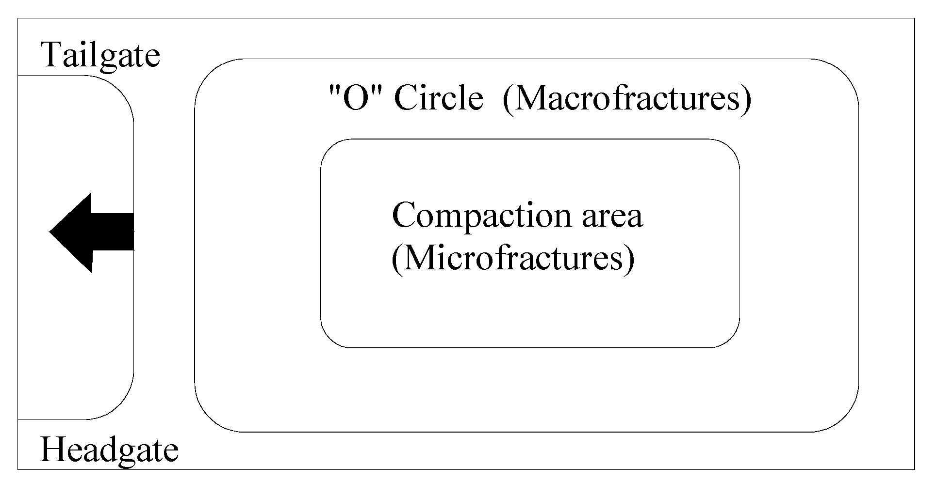
(1) “O” circle was found in the gob after the mining of protective coal seam. The area closes to pillar and coal face made up of the main macro-fractures for gas flow.
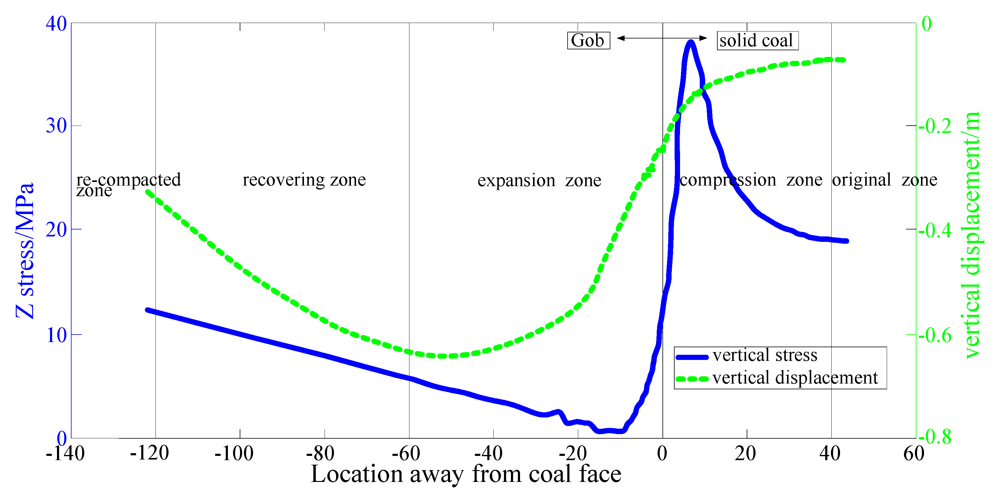
(2) The overburden of protective coal seam can be divided into 5 zones according to the distribution of stress and displacement in the mining horizon: the original zone, compression zone, expansion zone, recovering zone, and re-compacted zone; the expansion zone had largest permeability compared with other areas and was the best place for gas drainage.
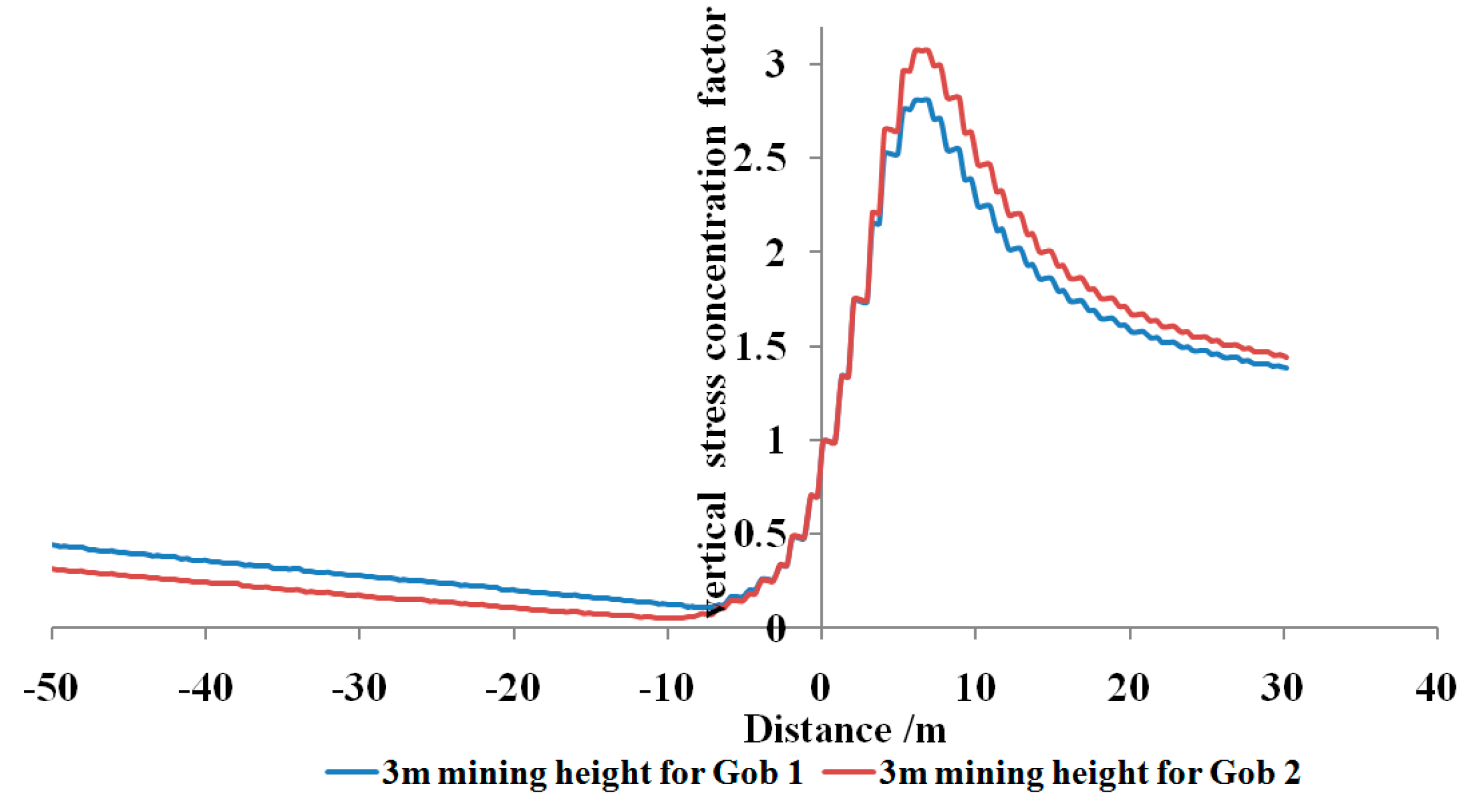
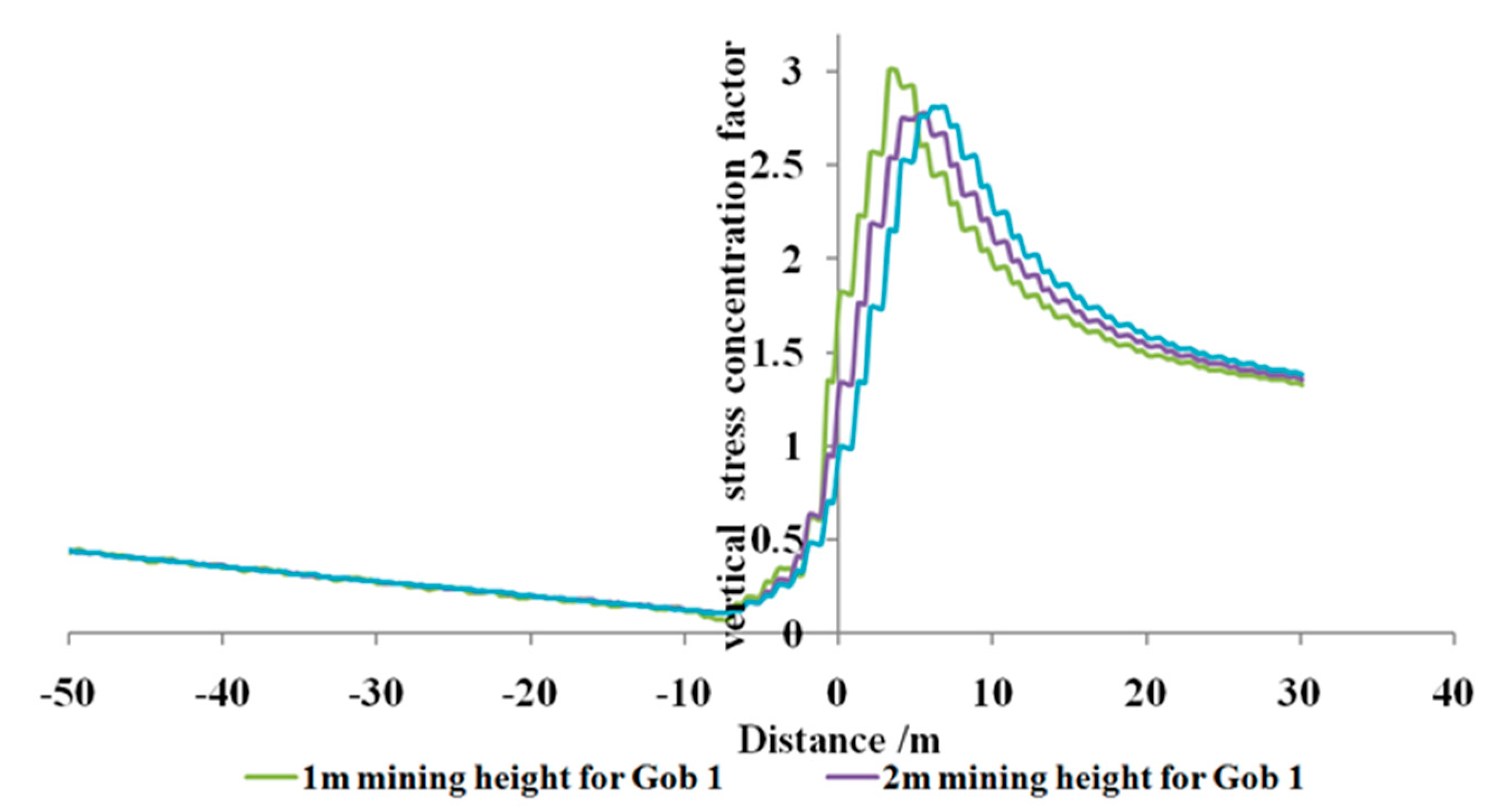
(3) The peak value of VSCF ahead of coal face increased with the increase of the stress recover distance; it decreased with mining height.
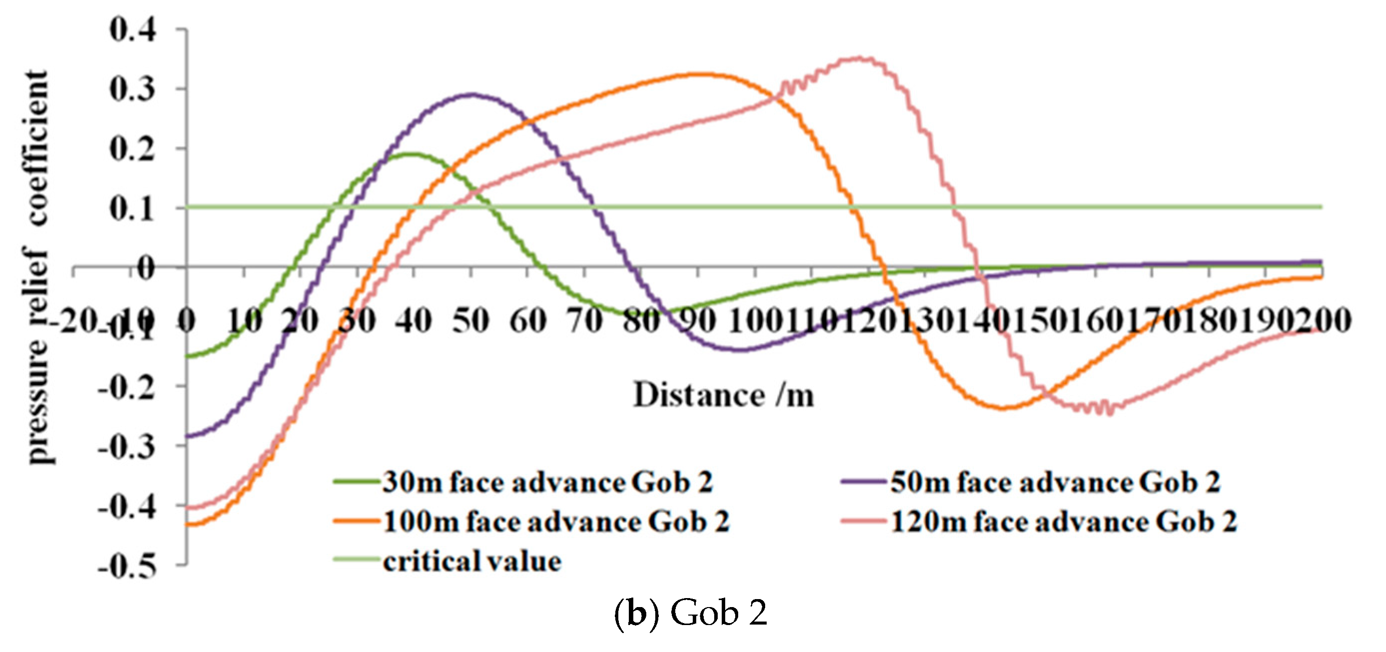
(4) For the same mining height with different gob behaviors of protective coal seam, the relief angles experienced the increase, decrease and stabilization process with face advancing in the coal face side; the relief angle was almost the same in the face area for different gob behaviors, indicating that it has little effect to the pressure relief of the face area.
(5) For the same gob behaviors with different mining height of protective coal seam, the mining height of protective coal seam mainly has an effect to the protected coal seam at the beginning of the mining process. This effect decreases and becomes very little when the coal seam is mined a certain distance. And the relief angle of 3 m mining height is always larger than 1m mining height with face advancing on the face side.
(6) Pressure relief scope in protected coal seam was acquired under specific mining condition. A combination gas drainage programs were provided for the case working face. The gas content reduced from 12.41 m3/t to 7.68 m3/t in 15 m range of roadway. It effectively prevented gas and coal outburst from occurring and reduced methane emission in roadway, and raised the advancing speed at the same time. And the research results can be used to guide the scope of gas drainage and highly improve gas drainage efficiency and reduce unnecessary work. More field data need to be collected for further research.

Author Contributions

C.Z. and Y.Z. conceived the main idea of the paper and designed the numerical model; C.Z. performed the numerical model; C.Z. and L.Y. analyzed the data; Y.Z. and R.F. contributed analysis tools and theoretical analysis; C.Z. wrote the paper; R.F. and G.Z. did a lot work to modify figures and proofread the revised version.

Funding

This paper was supported by the State Key Research Development Program of China (Grant No. 2016YFC0600708), CUMTB fund for creative PHD Student Project (00-800015z685), Tiandi Technology Co., Ltd. Technology Innovation Fund, China Scholarship Council (СSC), Zhongguancun Ten Hundred Thousand Special Project-7m High Mining Support Technology and Equipment (KJ-2017-GJGC-01). The authors would like to cordially acknowledge excellent guidance of Y.P. Chugh in Southern Illinois University Carbondale and G. Song in North China University of technology. The authors would also like to express special thanks to the editor and anonymous reviewers for their professional and constructive suggestion. In addition, C.Z. wants to thank, in particular, the patience, support and love from Y.Z. over the past years.

Conflicts of Interest

The authors declare no conflict of interest.

References

  1. Yang, W.; Lin, B.Q.; Qu, Y.A.; Zhao, S.; Zhai, C.; Jia, L.L.; Zhao, W.Q. Stress evolution with time and space during mining of a coal seam. Int. J. Rock Mech. Min. Sci. 2011, 48, 1145–1152. [Google Scholar] [CrossRef]
  2. Li, W.; Cheng, Y.P.; Guo, P.K.; An, F.H.; Chen, M.Y. The evolution of permeability and gas composition during remote protective longwall mining and stress-relief gas drainage: A case study of the underground Haishiwan Coal Mine. Geosci. J. 2014, 18, 427–437. [Google Scholar] [CrossRef]
  3. State Administration of Coal Mine Safety. Available online: http://english.gov.cn/state_council/2014/10/06/content_281474992926692.htm (accessed on 6 October 2014).
  4. Esterhuizen, G.S.; Karacan, C.O. Development of Numerical Models to InvestigatePermeability Changes and Gas Emission around Longwall Mining Panel. In Proceedings of the 40th U.S. Rock Mechanics Symposium (USRMS), Anchorage, AK, USA, 25–29 June 2005. [Google Scholar]
  5. Liu, R.C.; Li, B.; Jiang, Y.J. A fractal model based on a new governing equation of fluid flow in fractures for characterizing hydraulic properties of rock fracture networks. Comput. Geotech. 2016, 75, 57–68. [Google Scholar] [CrossRef]
  6. Li, B.; Liu, R.C.; Jiang, Y.J. Influences of hydraulic gradient, surface roughness, intersecting angle, and scale effect on nonlinear flow behavior at single fracture intersections. J. Hydrol. 2016, 538, 440–453. [Google Scholar] [CrossRef]
  7. Zhang, C.L.; Zhang, Y. Stress and Fracture Evolution Based on Abutment Change in Thick Coal Seam—A Case Study in China Colliery. Electron. J. Geotech. Eng. 2016, 21, 4369–4386. [Google Scholar]
  8. Lowndes, I.S.; Reddish, D.J.; Ren, T.X.; Whittles, D.N.; Hargreaves, D.M. Mine Ventilation: Proceedings of the North American/Ninth US Mine Ventilation Symposium; CRC Press: Boca Raton, FL, USA, 2002; pp. 267–272. [Google Scholar]
  9. Yang, W.; Lin, B.Q.; Qu, Y.A.; Zhao, S.; Zhai, C.; Jia, L.L.; Zhao, W.Q. Mechanism of strata deformation under protective seam and its application for relieved methane control. Int. J. Coal Geol. 2011, 85, 300–306. [Google Scholar] [CrossRef]
  10. Liu, Y.K.; Zhou, F.B.; Liu, L.; Liu, C.; Hu, S.Y. An experimental and numerical investigation on the deformation of overlying coal seams above double-seam extraction for controlling coal mine methane emissions. Int. J. Coal Geol. 2011, 87, 139–149. [Google Scholar]
  11. Hu, G.Z.; Wang, H.T.; Li, X.H.; Fan, X.G.; Yuan, Z.G. Numerical simulation of protection range in exploiting the upper protective layer with a bow pseudo-incline technique. Min. Sci. Technol. 2009, 19, 58–64. [Google Scholar] [CrossRef]
  12. Suchowerska, A.M.; Merifield, R.S.; Carter, J.P. Vertical stress changes in multi-seam mining under supercritical longwall panels. Int. J. Rock Mech. Min. Sci. 2013, 61, 306–320. [Google Scholar] [CrossRef]
  13. Peng, S.S.; Matsuki, K.; Su, W. 3-D Structural Analysis of Longwall Panels. In Proceedings of the 21st U.S. Symposium on Rock Mechanics (USRMS), Rolla, MO, USA, 27–30 May 1980; pp. 44–56. [Google Scholar]
  14. Whittaker, B.N. An Appraisal of Strata Control Practice: 4F, 4T, 30R. Int. J. Rock Mech. Min. Sci. Geomech. Abstr. 1974, 11, 9–24. [Google Scholar]
  15. Wilson, A.H.; Carr, F. A new approach to the design of multi-entry developments for retreat longwall Mining. In Proceedings of the Second Conference on Ground Control in Mining, Morgantown, WV, USA, 5–7 August 1982; pp. 1–21. [Google Scholar]
  16. Whittaker, B.N.; Singh, R.N. Evaluation of the design requirements and performance of gate roadways. Min. Eng. 1979, 138, 535–548. [Google Scholar]
  17. Campoli, A.A.; Timothy, B.; Dyke, F.C.V. Gob and Gate Road Reaction to Longwall Mining in Bump-Prone Strata; U.S. Dept. of the Interior, Bureau of Mines Bureau of Mines: Michigan, MI, USA, 1993; p. 48. [Google Scholar]
  18. Li, W.F.; Bai, J.B.; Peng, S.S.; Wang, X.Y.; Xu, Y. Numerical modeling for yield pillar design: A case study. Rock Mech. Rock Eng. 2015, 48, 305–318. [Google Scholar] [CrossRef]
  19. Esterhuizen, E.; Mark, C.; Murphy, M.M. The ground response curve, pillar loading and pillar failure in coal mines. In Proceedings of the 29th International Conference on Ground Control in Mining, Morgantown, WV, USA, 27–29 July 2010; pp. 19–27. [Google Scholar]
  20. Yavuz, H. An estimation method for cover pressure re-establishment distance and pressure distribution in the goaf of longwall coal mines. Int. J. Rock Mech. Min. Sci. 2004, 41, 193–205. [Google Scholar] [CrossRef]
  21. Esterhuizen, E.; Mark, C.; Murphy, M.M. Numerical model calibration for simulating coal pillars, gob and overburden response. In Proceedings of the 29th International Conference on Ground Control in Mining, Morgantown, WV, USA, 27–29 July 2010; pp. 46–57. [Google Scholar]
  22. Abbasi, B.; Chugh, Y.P.; Gurley, H. An Analysis of the Possible Fault Displacements Associated with a Retreating Longwall Face in Illinois. In Proceedings of the 48th US Rock Mechanics/Geomechanics Symposium, Minneapolis, MN, USA, 1–4 June 2014. [Google Scholar]
  23. Flac3D User’s Guide. Itasca Consulting Group, Inc. Available online: http://www.civil.utah.edu/~bartlett/CVEEN6920/FLAC%20manual.pdf (accessed on 5 June 2017).
  24. Jing, L. A review of techniques, advances and outstanding issues in numerical modelling for rock mechanics and rock engineering. Int. J. Rock Mech. Min. Sci. 2003, 40, 283–353. [Google Scholar] [CrossRef]
  25. Hoek, E.; Carranza-Torres, C.; Corkum, B. Hoek-Brown failure criterion-2002 edition. In Proceedings of the 5th North American Rock Mechanics Symposium and the 17th Tunnelling Association of Canada Conference (NARMS-TAC), Toronto, ON, Canada, 7–10 July 2002; pp. 267–273. [Google Scholar]
  26. Zhao, B.T.; Lin, B.Q. Methane Emission and Control Technology of “Three Soft” Unstable and Low Permeability Coal Seam Mining; China University of Mining and Technology Press: Xuzhou, China, 2007. (In Chinese) [Google Scholar]
  27. Qian, M.G.; Xu, J.L. Study on the “O” shape circle distribution characteristics of mining induced fractures in the overlaying strata. J. Chin. Coal Soc. 1998, 23, 466–468. (In Chinese) [Google Scholar]
  28. Yuan, Z.G.; Wang, H.T.; Hu, G.Z.; Li, X.H.; Fan, X.G.; Hong, S. Numerical simulation for protection scope of upper protective seam in steeply inclined multi-coal seam. J. Chin. Coal Soc. 2009, 34, 594–598. [Google Scholar]
  29. Maлышel, Ю.Н.; Фоменко, А.Т.; Дaлeцкий, Ю.Л. Forecast Method and Preventing Measure of Coal and Gas Burst; China Coal Industry Publishing House: Beijing, China, 2004. (In Chinese) [Google Scholar]
Figure 1. Relationship between permeability and normal stress [9] (Reproduced with permission from [9], Copyright Elsevier, 2011).
Processes 06 00146 g001
Figure 2. Illustration of protective coal seam mining.
Processes 06 00146 g002
Figure 3. A schematic plan view of two adjacent longwall faces in the numerical model, showing the geometry of the longwall faces. Both panel 1 and panel 2 represent half of original panel width in the studied mine site.
Processes 06 00146 g003
Figure 4. Strata pressure redistribution in the plane of the seam around a longwall face [16] (Reproduced with permission from [16], Copyright Elsevier, 1979).
Processes 06 00146 g004
Figure 5. Position relation of coal seams.
Processes 06 00146 g005
Figure 6. Flac3D model.
Processes 06 00146 g006
Figure 7. The plane schematic diagram of goaf mining fissure.
Processes 06 00146 g007
Figure 8. Vertical stress distribution in the roof of gob area.
Processes 06 00146 g008
Figure 9. Five zones above the protective coal seam along mining direction.
Processes 06 00146 g009
Figure 10. Contour of vertical stress along incline in the gob for 120 m face advance.
Processes 06 00146 g010
Figure 11. Vertical stress concentration factor in the face area of protected coal seam.
Processes 06 00146 g011
Figure 12. Vertical stress concentration factor with different mining height for Gob 1.
Processes 06 00146 g012
Figure 13. Pressure relief coefficient of protected coal seam with different gob behaviors for different face advance.
Processes 06 00146 g013aProcesses 06 00146 g013b
Figure 14. Pressure relief coefficient of protected coal seam with different mining height for different face advance.
Processes 06 00146 g014
Figure 15. Illustration of gas drainage during and after roadway excavation.
Processes 06 00146 g015
Figure 16. Diagram of the spatial configuration of the protected longwall and stress-relief gas drainage. (a) Horizontal plane view; (b) vertical section view.
Processes 06 00146 g016aProcesses 06 00146 g016b
Table 1. Basic parameters of No. 3 coal seam.
Coal SeamCoal FaceMining Thickness/mGas Content/m3/tOriginal Gas Pressure/MPaCoal StiffnessOutburst Risk
No. 34306 protected longwall face5.23 3.5–15.09 0.38–0.55 0.44–0.56Yes
No. 884306 protective longwall face1–3 2–3 None 0.51–1.12No
Table 2. Rock mass properties, GSI and Hoek-Brown parameters used in the numerical modeling.
Lithologyν σ c i / MPa GSImimbsaEm/MPa
3# Coal seam0.33675114.5040.06220.5012938.86
Fine grained sandstone0.1990901611.1950.32920.5006566.53
Medium grained sandstone0.207388159.7720.26360.5005020.52
Mudstone0.281680125.8740.10840.5013433.36
Sandstone0.244086137.8850.21110.5004203.05
Sandy mudstone0.263585137.0840.15120.5004095.07
Limestone0.197590106.9970.32920.5009682.03
8# Coal seam0.296.475114.5040.06220.2013020.50
Table 3. Parameters of each Flac3D model.
Model ParametersCover Pressure Re-Establishment Distance/mMining Height/m
Model 1Gob1-1201
Model 2Gob1-1202
Model 3Gob1-1203
Model 4Gob2-1403
Table 4. Relief angles change along strike with different gob behaviors for different face advance.
Face Advance30 m50 m100 m120 m
Gob12121212
Set up room/°82.082.074.574.555.261.041.355.2
Coal face/°82.082.080.680.676.076.076.076.0
Table 5. Relief angles along strike with different mining height for different face advance.
Face Advance30 m50 m70 m120 m
Ming height/m31313131
Set-up room/°82.074.574.571.664.763.541.341.3
Coal face/°82.077.580.676.077.574.576.068.1
Table 6. Pressure relief scope in protected coal seam.
Face Advance30 m50 m70 m100 m120 m
Ming height/m3131313131
Gob 1/m271941365249737772
Gob 2/m27417893
Table 7. The results after gas drainage by floor tunnel 1.
No.ParametersBefore Gas DrainageAfter Gas Drainage
1Average gas content/m3/t12.417.68
2Maximum gas emission during roadway excavation/m3/min7.53.48
3Gas outburst prevention index K1Average value0.4–0.420.32–0.33
Exceed or notYN
4Roadway excavation speedExcavation footage/m2.45–7
Weather gas affect roadway excavation or notYN
Table 8. The borehole parameters of 4306 floor tunnel 2.
Singular GroupEven Group
No.Dip/iAzimuth/zDepth/mNo.Dip/iAzimuth/zDepth/m
11427070.511527065.5
21627060.521827056
3192705132127046.5
42327041.542627037
52927032.553427028
64127024.565127020.5
76127018.575620019.5
8571771985515619.5
9599018.59489021.5
1040902510349028.5
11299032.511269037
12239041.512209046.5
1318905113179056
14169060.514159065.5
15149070.5

