Article

Ionic Liquid (1-Butyl-3-Metylimidazolium Methane Sulphonate) Corrosion and Energy Analysis for High Pressure CO2 Absorption Process

Department of Chemical and Materials Engineering, Faculty of Engineering, King Abdulaziz University, Jeddah 21589, Saudi Arabia
*
Author to whom correspondence should be addressed.
Processes 2018, 6(5), 45; https://doi.org/10.3390/pr6050045
Submission received: 7 April 2018 / Revised: 23 April 2018 / Accepted: 24 April 2018 / Published: 1 May 2018

Abstract

:
This study explores the possible use of ionic liquids as a solvent in a commercial high-pressure CO2 removal process, to gain environmental and energy benefits. There are two main constraints in realizing this: ionic liquids can be corrosive, specifically when mixed with a water/amine solution with dissolved O2 & CO2; and CO2 absorption within this process is not very well understood. Therefore, scavenging CO2 to ppm levels from process gas comes with several risks. We used 1-butyl-3-methylimidazoium methane sulphonate [bmim][MS] as an ionic liquid because of its high corrosiveness (due to its acidic nature) to estimate the ranges of expected corrosion in the process. TAFEL technique was used to determine these rates. Further, the process was simulated based on the conventional absorption–desorption process using ASPEN HYSYS v 8.6. After preliminary model validation with the amine solution, [bmim][MS] was modeled based on the properties found in the literature. The energy comparison was then provided and the optimum ratio of the ionic liquid/amine solution was calculated.

1. Introduction

Anthropogenic carbon dioxide (CO2) removal systems are used in various chemical industries and in various processes or to gain carbon credits [1]. In many processes, its absorption from synthesis gas is a crucial parameter in order for downstream catalysts to work (usually allowing slippage <500 ppm) [2]. Major design constraints include the loading rate, CO2 slippage limit and energy extensiveness. Absorption by solvents is a common practice employed in various industries [3].
Although there are many techniques reported in literature to capture CO2 [4,5,6] until now only chemical solvent-based processes promise to achieve low slippage at high loading rates commercially. Many amines were studied for their CO2 absorption capacity, but amines like methyl ethanolamine (MEA), diethanolamine (DEA), methyl diethanolamine (MDEA), piperazine (PZ), triethanolamine (TEA), and 2-amino-2-methyl-1-propanol (AMP) show better results in terms of stability and efficacy [7]. Commercial solvents are made up of concoctions of various chemicals that include optimum combinations of amines, corrosion inhibitors, antifoaming agents, and other proprietary additives. These amines mixtures have been commercialized under different names [8,9,10,11,12,13]. CO2 is captured by reversible chemical reactions within these amines. The rate of reaction depends on the bulk concentration of CO2. A simple solvent-based CO2 absorption scheme consists of a stripper and an absorber at low and high pressure respectively; however, this kind of scheme is extensive in terms of energy/cost [14]. Regeneration of these solvents requires steam and is thus a major energy consuming unit operation. Current literature focuses on two techniques in response to this problem: discovery of a solvent that requires less decomposition energy to liberate CO2 [15,16], or restructuring the process to economize pressure and heat energy recovery [17,18,19,20,21,22]. Therefore, development of new solvents requiring less drastic conditions without compromising CO2 slippage remains an attractive area of research [23].
Pure ionic liquids are also reported to absorb CO2 [24,25]. Furthermore, amine groups are functionalized with ionic liquids to synergize the effects of reaction and absorption in the same molecule [26,27]. This is reported to enhance the CO2 recovery [28]. Ionic liquids also offer the advantage of low vapor pressure, decreasing unwanted loss in the stripped stream at high temperatures. However, ionic liquids have process issues related to corrosion and crystallization.
Corrosion of metals in amine solutions is well known [22,29]. The commercial amine mixture solvents usually have some corrosion inhibitor or passivators to deal with the detrition of metallic parts [30]. The corrosion by amine/ionic liquid mixtures is foreseen [31]. Ionic liquids are salts and can extremely affect the corrosion of various metals, as their hydrolysis can be significantly different [32]. In this study, 1-butyl-3-metylimidazoium methane sulphonate [bmim][MS] was chosen as a model molecule in the design of an ionic liquid-based process. At 60 °C, absorption of 0.25 mol CO2/mol IL at 5 MPa is reported [33]. The addition of water to the solution has mixing and transfer benefits that can result in energy efficiency due to decreases in viscosity. The surface tension of [bmim][MS] decreased when mixed with water, thus increasing the mass transfer coefficient [34].

2. Materials and Methods

1-Butyl-3-methylimidazolium methanesulfonate [bmim][MS] was provided by Ionic Liquid Technologies, Helibronn, DE (io.li.tec) with a purity of 99.6–99.9% and 98.5–99.9% respectively. Diethylethanol amine and piprazine were purchased from Sigma Aldrich, Al-Khobar, KSA. Three-electrode system was used to carry out electrochemical tests on a PG STAT-101 potentiostat, provided by AUTOLAB and powered by NOVA software. Ag/AgCl was used as a standard electrode with a platinum electrode as the counter electrode. The sample coupon of carbon steel was grinded and polished. The sample coupon was also washed with distilled water and ethanol before testing. Temperature was controlled manually by oil circulation in the cell jacket. All experiments were done at atmospheric pressure. Pure carbon dioxide was bubbled through the solution continuously (≈1 mL/min). Electrodes were immersed and left for 30 min to achieve a steady state before any measurement. Open circuit potential was first measured and ±100 mv range to open circuit potential is adjusted for Tafel scan. Scan rate was fixed at 1 mv/s. Each experiment was repeated thrice. Uncertainty in the results was less than ±7%.
Differential Scanning Calorimeter was provided by Netzch, Selb, DE (DSC 200 F3). The samples (about 10–15 mg) were initially heated to 100 °C to erase the thermal history, then cooled to room temperature, and finally heated at 1 °C per min from ≈25 °C to 120 °C. Aluminum crucible with pierced lid was used. The obtained thermograms were used to determine the glass transition/melting temperature of the ionic liquids.

3. Results & Discussion

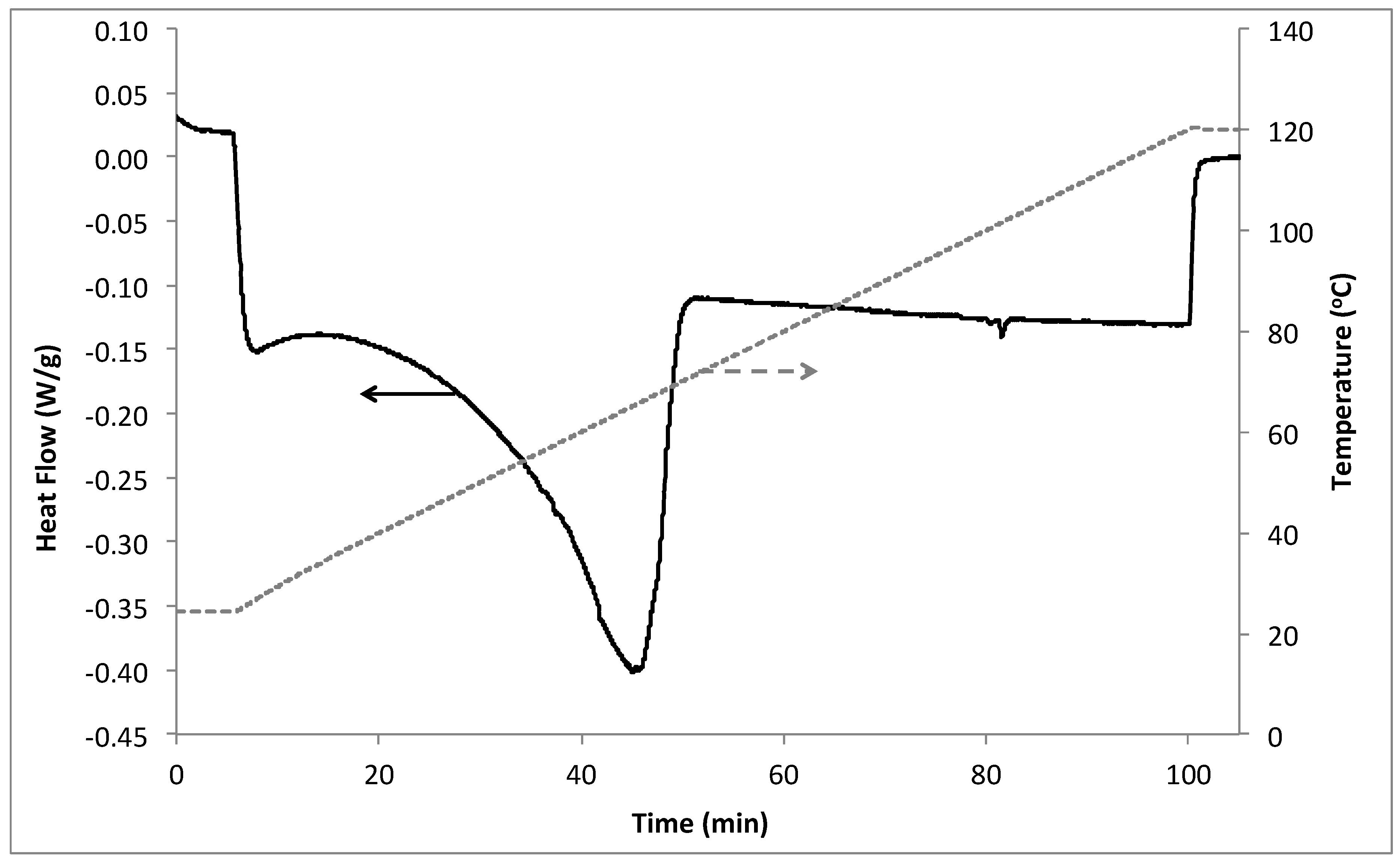
3.1. Differential Scanning Calorimetry
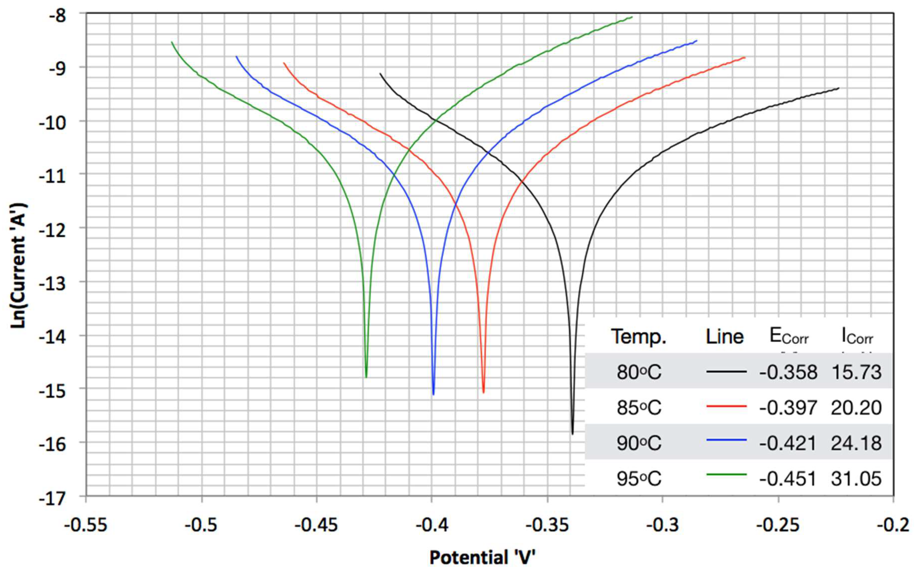
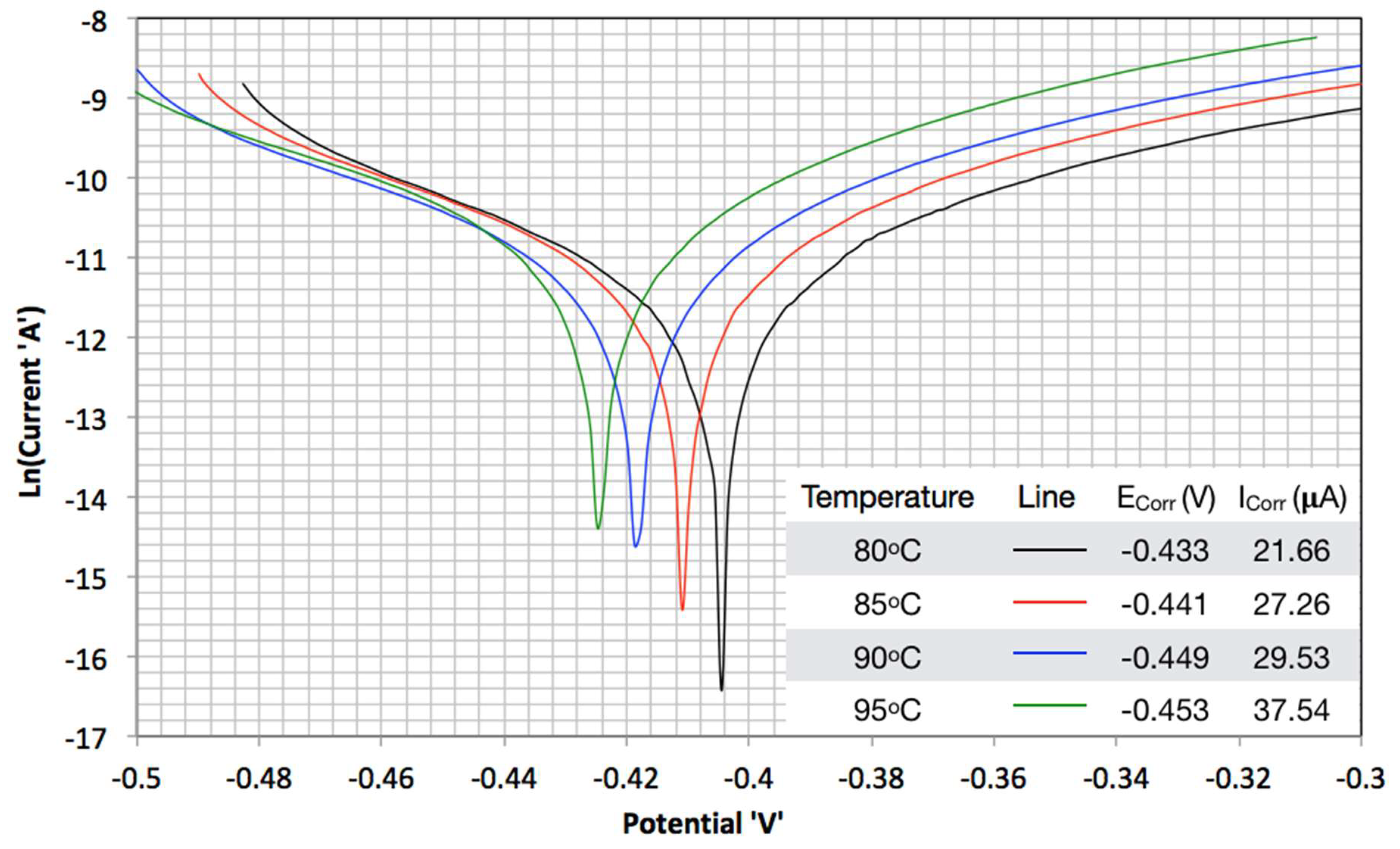
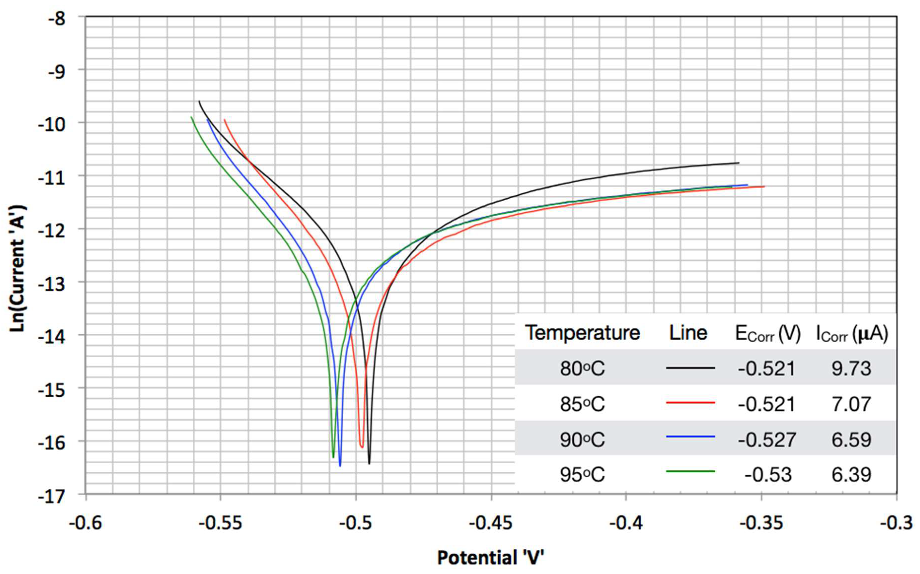
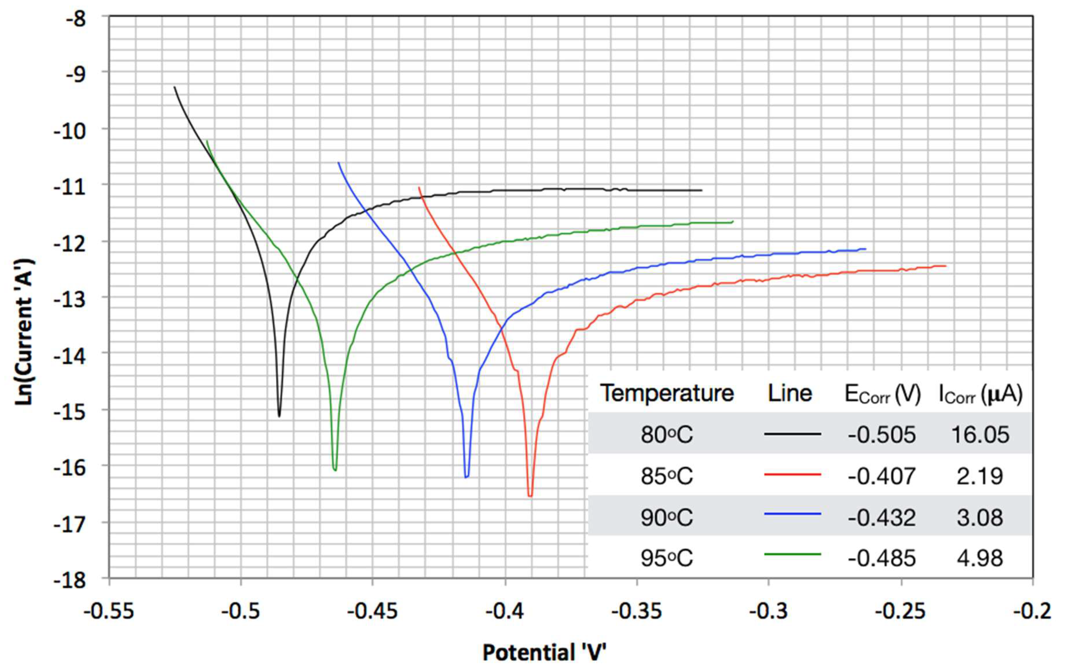
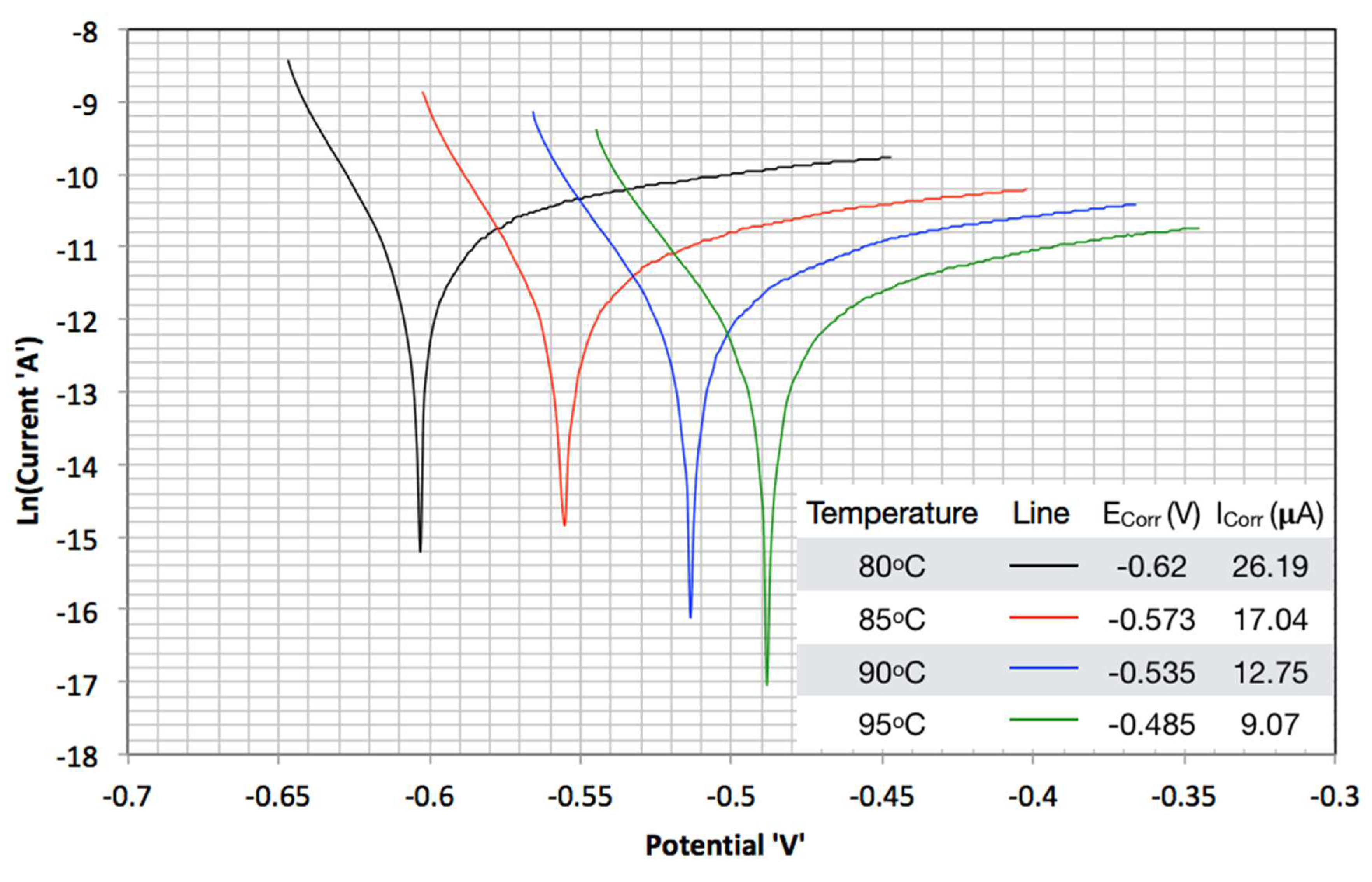
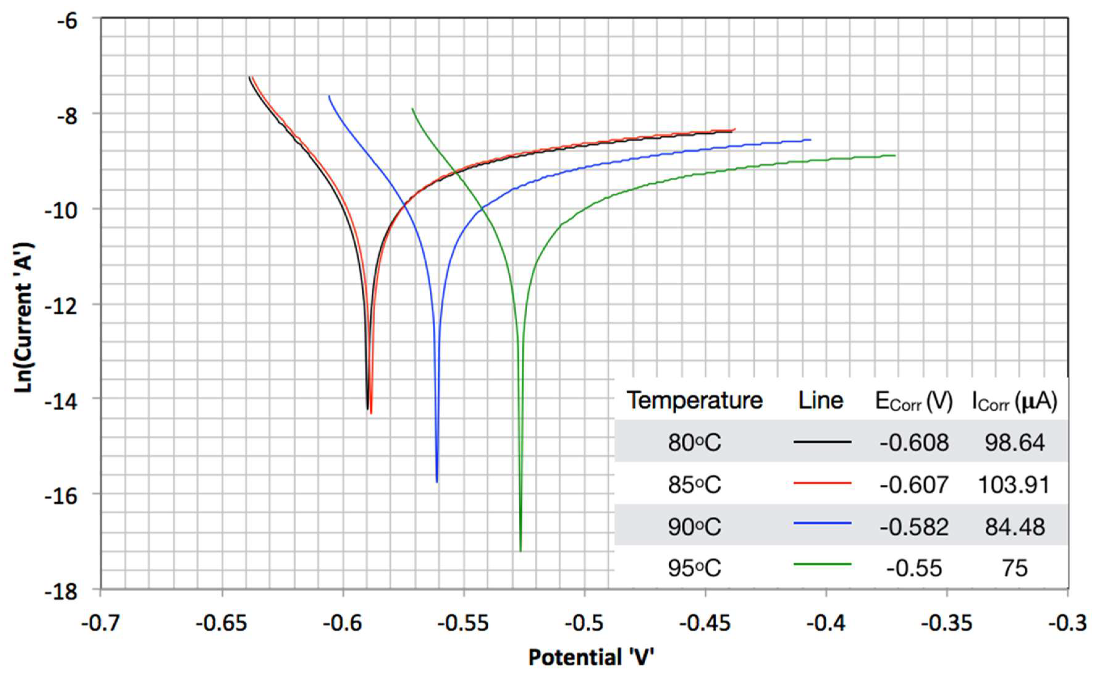
The differential scanning calorimetry (DSC) results are shown in Figure 1. As [bmim][MS] is a strong hydrophilic ionic liquid and can absorb moisture from the environment, care was taken to keep contact between the ionic liquid and the environment to a minimum, to avoid water ingression after sample preheating. However, it cannot be completely avoided. The valley started immediately after heating began. This was attributed to the vaporization of the absorbed water. The exact melting point for the ionic liquid is hard to measure but [bmim][MS] must be kept above 65 °C to avoid crystallization in the CO2 absorption process. The heat capacity data (above 65 °C) obtained from the DSC was also used to model the process, as described in the next section. No decomposition of the ionic liquid was physically observed below 100 °C. Moreover, after cooling of DSC samples there was no/negligible weight loss. Kärkkäinen discussed the stability of the ionic liquids and reported [bmim][MS] decomposition onset temperature as 335 °C. Therefore, it is assumed that no decomposition of the ionic liquid occurs at the process conditions described in the simulation section [35].

3.2. TAFEL Curves

Figure 2 and Figure 3 present the Tafel curves obtained without and with carbon dioxide for pure [bmim][MS] respectively. Corrosion current is reported per unit area (cm2) of the exposed surface. Corrosion rates are obtained by the standard procedure of Tafel slopes. The rate of corrosion increased with temperature because of the enhanced mobility of the ions and charge transfer. It is also shown that carbon dioxide absorption in water lowers the pH of water, thus increasing the oxidation rates. The same was observed for [bmim][MS]. As there is no water present the increase in corrosion rates is attributed to the enhanced charge mobility by [bmim][MS]. CO2 was physically absorbed on the ionic liquid, structural modification of imidazole cation is shown by the published data of Jung et al. [33]. Increase in CO2 absorption by longer chain cations than [bmim] further strengthens the view that the cation is a major source of CO2 absorption. The slopes of the Tafel curves suggest that cation charge transfer controls the oxidation rates. This is true both with and without CO2. Results suggest that the CO2 absorption on cation enhances its mobility in the solution.
Corrosion rates drop sharply when amine solution (40%MDEA, 2%PZ, 58%H2O) is mixed with [bmim][MS], as presented by Figure 4 and Figure 5. Amine saturated with CO2 has corrosion current rates for carbon steel in the range of 3 to 4 μA [28]. The perturbation in Figure 5 can be attributed to noise. As the solution becomes more conductive, more noise is expected due to increase in the sensitivity levels. Amine introduces a strong inhibition effect on corrosion for ionic liquids. However, this is not true if the concentration of the amine solution is increased beyond a certain threshold. This can be observed from the results presented in Figure 6 and Figure 7. For any commercial process, such corrosion rates are usually not acceptable. Furthermore, the corrosion rates drop with increase in temperature.

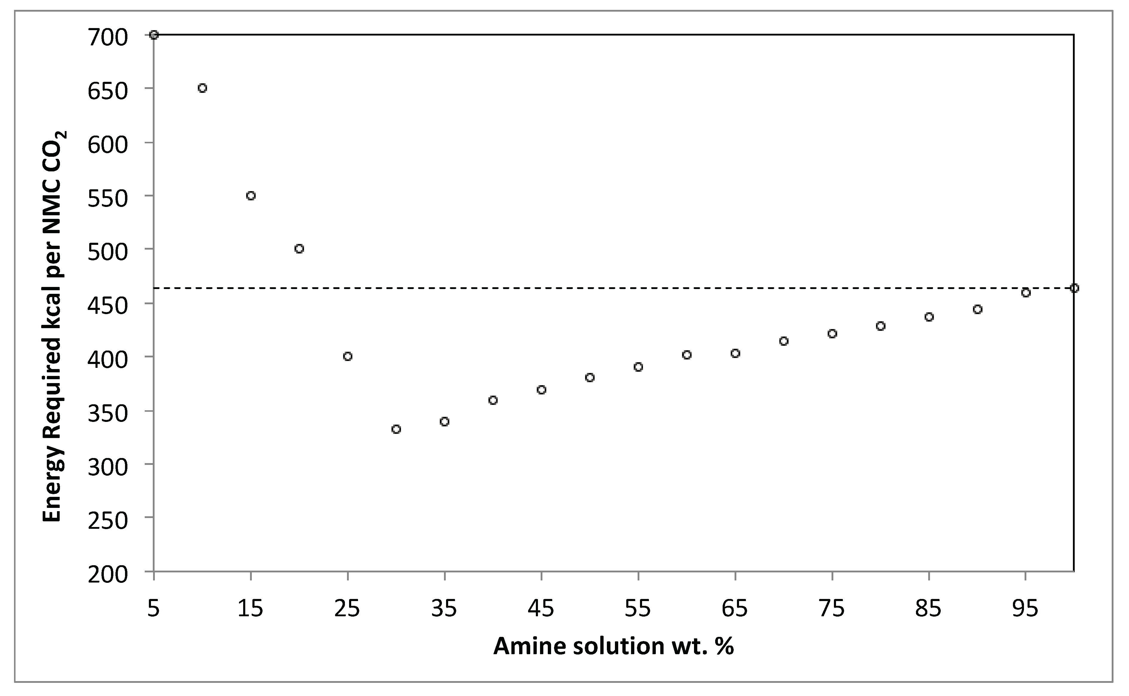
3.3. Process Simulation and Validation

3.3.1. Existing Facility Model

Zwitterion mechanism is considered responsible for CO2 absorption by amines [36,37]. The reactions are provided in Table 1. The first five reactions are considered to be in quasi-state equilibrium. The rest of the reactions are used to model the CO2 absorption based on the mass transfer coefficient and kinetics. These reactions along with the Electrolyte Non-Random Two Liquids (ENRTL) method form ‘ACID GAS’ package (specifically designed for amine-based solvents) for thermodynamic calculations using ASPEN HYSYS V 8.6 (Aspen Technology, Inc., Bedford, MA, USA). A similar technique was used by Greer et al. to simulate the CO2 absorption process (solvent MEA) but using the Peng–Robinson model. Furthermore, absorption has been modeled using chemical reaction and Henry’s law [38].
Figure 8 shows the simple process flow diagram. Process gas is produced by reforming and is available at high temperature and pressure (78 °C, 33 bar). The gas contains 59%H2, 18%CO2, 20%N2, and the rest is water, methane and traces of H2S (mol basis). The process is designed to economize the process for stripping the rich amine solution (1–2). After cooling, this gas is passed through the absorber and the clean process gas is available (3–4). The downstream processes are designed based on the maximum CO2 contents of 500 ppm. The absorber is divided into two sections. The upper section receives the lean amine solution from the stripper and works on approach to equilibrium (20–22). The lower section is at high temperature and receives comparatively hot semilean solution from intermediate flashing scheme (12–14). The lower absorber section thus enhances the CO2 absorption kinetics, which is slower in the upper section. The high-pressure rich amine solution is then depressurized in a turbine to feed the high-pressure flash drum. This flash drum pressure is optimized to recover hydrogen and nitrogen that is absorbed along with CO2. As flash gas contains high contents of acid gas, it is therefore recycled back to the absorber (5–7). The amine solution then goes to the low-pressure flash drum. The pressure in this flash drum is equal to the stripper. The purpose of this flash drum is to split the amine flow to feed both the stripper and the lower part of the absorber (13–16). The acid gas is also recovered from this flash drum (10). Downstream stripper is used to produce the lean solution, almost free of acid gas, to feed the absorber upper section (17–22).
The process simulation is validated according to the real industrial data as shown in Table 2. Industrial maximum and minimum value is obtained from the three years steady state operational log. The close proximity of the process parameters with the model provides the confidence to use the same package for amine solution in ionic liquid mixture. The same model will be used to design the process based on ionic liquid and amine solution mixture.

3.3.2. Absorption Process with Ionic Liquid

Ionic liquids cannot be modeled with an ‘ACID GAS’ package. In ASPEN HYSYS it is modeled as a hypothetical molecule. The equation of state is used to define its properties. Pereiro et al. provide different properties [39]. The density data and molecular weight of the ionic liquid is used to estimate the critical properties of the hypothetical molecule. The solubility of the carbon dioxide in the ionic liquid is regressed as a polynomial, based on the data available in the literature [33] (at low pressure <5 MPa, it can be considered a straight line). The process using an ionic liquid is modeled as parallel to the existing process, but without mixing with amine solution (solution of amine and ionic liquid is assumed as an ideal mixture i.e., mixture properties are just the summation of pure species property with entropy adjustment with no chemical reaction between amine and [bmim][MS]). Task-specific ionic liquids (TSIL) are tailored—usually cation functionalized ionic liquids enhance CO2 absorption. The immidazolium-based cation is functionalized and it is reported to increase CO2 absorption by threefold for ionic liquids [40,41]. The functionalization mechanism usually involves specific radicals and ion exchangers. Furthermore, the immidazolium cation functionalization, with CO2 absorption, increases the solution viscosity to a gel-like substance [42]. At the process conditions, it is highly unlikely to have a functionalization reaction between amine and [bmim][MS], as the exponential increase in viscosity was not observed in our corrosion experimentation. Any side reaction kinetics is assumed to be negligible due to the long chain diffusion limitations. Functionalization can increase the absorption of CO2 but gravimetrically due to lower CO2 loadings it is not feasible to use these TSIL alone in commercial processes [43].
Vapor pressure of the ionic liquid is taken as negligible. In the case of an ionic liquid mixed with the amine, the temperature of the process is kept above 65 °C. First, the carbon dioxide is absorbed in the ionic liquid according to the equilibrium relation obtained from the regression. Then the resulting gas is contacted with the amine solution. No dissolution of any other gas is considered in the process modeling of the ionic liquid, so a high-pressure flash drum is not required with ionic liquids. If only ionic liquid, without amine, is considered then in practice it is not possible to lower the amount of CO2 in purified gas to 500 ppm. The pure ionic liquid has a tendency of crystallize. Furthermore, its high viscosity may result in extensive pressure drops. Therefore, amine/water solution is required to polish the gas by scavenging remaining carbon dioxide to acceptable levels, to avoid [bmim]z crystallization and to lower its viscosity. Viscosity is reported to decrease with the addition of water and is comparable with amine solution (30 wt. % ionic liquid, 20 °C, 0.1 MPa, amine viscosity ≈ 4 mPa·s, [bmim][BF4] ≈ 2 mPa·s) [44,45]. The ratio between amine solution and ionic liquid is fixed and their total quantities are adjusted to achieve the purity level of 500 ppm. Figure 9 shows the relation between the amount of energy required per NMC of the carbon dioxide removal and the percentage of amine solution mixed with the modeled [bmim][MS]. There exists an optimum mixture of ≈27% with the minimum amount of energy required.

4. Conclusions

The current study provides initial estimates for using ionic liquid [bmim][MS] for carbon dioxide removal. The corrosion rates of amines are considerably less than the ionic liquids, but the combined effect of both the solvents has a weight percent threshold limit. Extreme corrosion rates are expected and advanced corrosion mitigation techniques must be considered for the process design Usually commercial solvent recipes for CO2 removal come with corrosion inhibitors. The role of these inhibitors should be enhanced for any ionic liquid inclusion. The ASPEN HYSYS ‘ACID GAS’ package provides an excellent estimation of the amine properties and corresponds very well with the industrial data. Modeling of ionic liquids is not very mature and requires certain assumptions, because of the lack of available data. The built-in ‘COSMOSAC’ model (in ASPEN) does not provide good estimates in the case of [bmim][MS]. It is therefore modeled using primitive techniques, thus slight discrepancies in the results are expected that can be addressed with more experimental data input. Nevertheless, it can be concluded with sufficient evidence that an optimal mixing ratio exists, when using ionic liquid for high-pressure commercial CO2 removal process under different conditions.

Author Contributions

Major simulation and corrosion experimentation was conducted by A.A.T., S.A.-S. provided the valuable discussion and guidance for the experimentation. A.M. provided the much-needed insight to model and properties estimation of the ionic liquids

Funding

This Project was funded by the Deanship of Scientific Research (DSR), King Abdulaziz University, Jeddah, under grant No. (1434/135/253). The authors, therefore, acknowledge with thanks DSR technical and financial support.

Conflicts of Interest

The authors declare no conflict of interest.

References

  1. Yang, H.; Xu, Z.; Fan, M.; Gupta, R.; Slimane, R.B.; Bland, A.; Wright, I. Progress in carbon dioxide separation and capture: A review. J. Environ. Sci. 2008, 20, 14–27. [Google Scholar] [CrossRef]
  2. Taimoor, A.A.; Pitault, I.; Meunier, F.C. Correlation between deactivation and Pt-carbonyl formation during toluene hydrogenation using a H2/CO2 mixture. J. Catal. 2011, 278, 153–161. [Google Scholar] [CrossRef]
  3. Aaron, D.; Tsouris, C. Separation of CO2 from Flue Gas: A. Review. Sep. Sci. Technol. 2005, 40, 321–348. [Google Scholar] [CrossRef]
  4. Shi, X.; Xiao, H.; Lackner, K.S.; Chen, X. Capture CO2 from ambient air using nanoconfined ion hydration. Angew. Chem. Int. Ed. Eng. 2016, 55, 4026–4029. [Google Scholar] [CrossRef] [PubMed]
  5. Shi, X.; Li, Q.; Wang, T.; Lackner, K.S. Kinetic analysis of an anion exchange absorbent for CO2 capture from ambient air. PLoS ONE 2017, 12, e0179828. [Google Scholar] [CrossRef] [PubMed]
  6. Yu, C.-H. A Review of CO2 Capture by Absorption and Adsorption. Aerosol Air Qual. Res. 2012, 12, 745–769. [Google Scholar] [CrossRef]
  7. Gomes, J.; Santos, S.; Bordado, J. Choosing amine-based absorbents for CO2 capture. Environ. Technol. 2015, 36, 19–25. [Google Scholar] [CrossRef] [PubMed]
  8. Reddy, S.; Johnson, D.; Gilmartin, J. Fluor’s Econamine FG Plus Technology for CO2 Capture at Coal-fired Power Plants. In Proceedings of the Power Plant Air Pollutant Control “Mega” Symposium, Baltimore, MD, USA, 25–28 August 2008; pp. 1–17. [Google Scholar]
  9. Johnson, D.W.; Reddy, S.; Brown, J.H. Commercially Available CO2 Capture Technology. Available online: http://www.powermag.com/commercially-available-co2-capture-technology/?printmode=1 (accessed on 9 February 2016).
  10. Milidovich, S.; Zbacnik, E. Increasing Efficiency of Hot Potassium Carbonate CO2 Removal Systems; UOP LLC: Des Plaines, IL, USA, 2013; pp. 11–14. [Google Scholar]
  11. Eickmeyer, A.G. The Catalysis of Potassium Carbonate Solutions in Carbon Dioxide Absorption. In Proceedings of the Fall Meeting of the Society of Petroleum Engineers of AIME, Dallas, TX, USA, 8–11 October 1961. [Google Scholar]
  12. DOW oil and Gas Solutions. Available online: http://www.dow.com/en-us/oil-gas-mining/oil-and-gas-solutions/gas-processing (accessed on 9 February 2016).
  13. BASF. OASE Gas Treating Excellence. Available online: http://www.intermediates.basf.com/chemicals/web/en/function/conversions:/publish/content/news-and-publications/brochures/download/BASF_Oase_Gas-Treatment.pdf (accessed on 26 April 2018).
  14. Mumford, K.A.; Wu, Y.; Smith, K.H.; Stevens, G.W. Review of solvent based carbon-dioxide capture technologies. Front. Chem. Sci. Eng. 2015, 9, 125–141. [Google Scholar] [CrossRef]
  15. Karande, R.; Halan, B.; Schmid, A.; Buehler, K. Segmented flow is controlling growth of catalytic biofilms in continuous multiphase microreactors. Biotechnol. Bioeng. 2014, 111, 1831–1840. [Google Scholar] [CrossRef] [PubMed]
  16. Zhu, D.; Fang, M.; Lv, Z.; Wang, Z.; Luo, Z. Selection of Blended Solvents for CO2 Absorption from Coal-Fired Flue Gas. Part 1: Monoethanolamine (MEA)-Based Solvents. Energy Fuels 2012, 26, 147–153. [Google Scholar] [CrossRef]
  17. Cousins, A.; Wardhaugh, L.T.; Feron, P.H.M. A survey of process flow sheet modifications for energy efficient CO2 capture from flue gases using chemical absorption. Int. J. Greenh. Gas Control 2011, 5, 605–619. [Google Scholar] [CrossRef]
  18. Reddick, C.; Li, C.; Sorin, M.; Sapoundjiev, H. Lowering the energy cost of carbon dioxide capture using ejectors for waste heat upgrading. Energy Procedia 2014, 63, 715–726. [Google Scholar] [CrossRef]
  19. Ding, J.; Lin, Y.-J.; Rochelle, G.T. Optimization of stripping piperazine with variable rich loading. Energy Procedia 2014, 63, 1842–1853. [Google Scholar] [CrossRef]
  20. Sachde, D.; Rochelle, G.T. Absorber Intercooling Configurations using Aqueous Piperazine for Capture from Sources with 4 to 27% CO2. Energy Procedia 2014, 63, 1637–1656. [Google Scholar] [CrossRef]
  21. Kothandaraman, A.; Nord, L.; Bolland, O.; Herzog, H.J.; McRae, G.J. Comparison of solvents for post-combustion capture of CO2 by chemical absorption. Energy Procedia 2009, 1, 1373–1380. [Google Scholar] [CrossRef]
  22. Desideri, U.; Paolucci, A. Performance modelling of a carbon dioxide removal system for power plants. Energy Convers. Manag. 1999, 40, 1899–1915. [Google Scholar] [CrossRef]
  23. Kumar, P.S.; Hogendoorn, J.A.; Feron, P.H.M.; Versteeg, G.F. New absorption liquids for the removal of CO2 from dilute gas streams using membrane contactors. Chem. Eng. Sci. 2002, 57, 1639–1651. [Google Scholar] [CrossRef]
  24. Scovazzo, P. Regular Solution Theory and CO2 Gas Solubility in Room-Temperature Ionic Liquids. Ind. Eng. Chem. Res. 2004, 43, 6855–6860. [Google Scholar] [CrossRef]
  25. Karadas, F.; Atilhan, M.; Aparicio, S. Review on the use of ionic liquids (ILs) as alternative fluids for CO2 capture and natural gas sweetening. Energy Fuels 2010, 24, 5817–5828. [Google Scholar] [CrossRef]
  26. Camper, D.; Bara, J.E.; Gin, D.L.; Noble, R.D. Room-temperature ionic liquid-amine solutions: Tunable solvents for efficient and reversible capture of CO2. Ind. Eng. Chem. Res. 2008, 47, 8496–8498. [Google Scholar] [CrossRef]
  27. Budzianowski, W.M. Energy Efficient Solvents for CO2 Capture by Gas-Liquid Absorption: Compounds, Blends and Advanced Solvent Systems; Springer International Publishing: New York, NY, USA, 2016. [Google Scholar]
  28. Brennecke, J.F.; Gurkan, B.E. Ionic Liquids for CO2 Capture and Emission Reduction. J. Phys. Chem. Lett. 2010, 1, 3459–3464. [Google Scholar] [CrossRef]
  29. Veawab, A.; Tontiwachwuthikul, P.; Amit, C. Corrosion Behavior of Carbon Steel in the CO2 Absorption Process Using Aqueous Amine Solutions. Ind. Eng. Chem. Res. 1999, 38, 3917–3924. [Google Scholar] [CrossRef]
  30. DuPart, M.; Bacon, T.; Edwards, D. Understanding corrosion in alkanolamine gas treating plants: Part 1. Hydrocarb. Process. 1993, 72, 75–80. [Google Scholar]
  31. Hasib-ur-rahman, M.; Bouteldja, H.; Fongarland, P.; Siaj, M. Corrosion Behavior of Carbon Steel in Alkanolamine/Room-Temperature Ionic Liquid Based CO2 Capture Systems. Ind. Eng. Chem. Res. 2012, 51, 8711–8718. [Google Scholar] [CrossRef]
  32. Shi, X.; Xiao, H.; Chen, X.; Lackner, K.S. The Effect of Moisture on the Hydrolysis of Basic Salts. Chem. Eur. J. 2016, 22, 18326–18330. [Google Scholar] [CrossRef] [PubMed]
  33. Jung, Y.-H.; Jung, J.-Y.; Jin, Y.-R.; Lee, B.-C.; Baek, I.-H.; Kim, S.-H. Solubility of Carbon Dioxide in Imidazolium-Based Ionic Liquids with a Methanesulfonate Anion. J. Chem. Eng. Data 2012, 57, 3321–3329. [Google Scholar] [CrossRef]
  34. Paul, S.; Panda, A.K. Physicochemical investigations on the aqueous solution of an ionic liquid, 1-butyl-3-methylimidazolium methanesulfonate, [bmim][MS], in a concentrated and dilute regime. Colloids Surf. A Physicochem. Eng. Asp. 2012, 404, 1–11. [Google Scholar] [CrossRef]
  35. Kärkkäinen, J. Preperation and Characterization of Some Ionic Liquids and Their Use in the Dimerization Recation of 2-Methylpropene. Ph.D. Thesis, University of Oulu, Oulu, Finland, 9 March 2007. [Google Scholar]
  36. Caplow, M. Kinetics of carbamate formation and breakdown. J. Am. Chem. Soc. 1968, 90, 6795–6803. [Google Scholar] [CrossRef]
  37. Danckwerts, P.V. The reaction of CO2 with ethanolamines. Chem. Eng. Sci. 1979, 34, 443–446. [Google Scholar] [CrossRef]
  38. Greer, T.; Bedelbayev, A.; Igreja, J.M.; Gomes, J.F.; Lie, B. A simulation study on the abatement of CO2 emissions by de-absorption with monoethanolamine. Environ. Technol. 2010, 31, 107–115. [Google Scholar] [CrossRef] [PubMed]
  39. Pereiro, A.B.; Verdía, P.; Tojo, E.; Rodríguez, A. Physical properties of 1-butyl-3-methylimidazolium methyl sulfate as a function of temperature. J. Chem. Eng. Data 2007, 52, 377–380. [Google Scholar] [CrossRef]
  40. Bates, E.D.; Mayton, R.D.; Ntai, I.; Davis, J.H., Jr. CO2 Capture by a Task-Specific Ionic Liquid. J. Am. Chem. Soc. 2002, 9, 926–927. [Google Scholar] [CrossRef]
  41. Galán Sánchez, L.M.G.; Meindersma, G.W.; de Haan, A.B. Solvent properties of Functionalized Ionic Liquids for CO2 Absorption. Chem. Eng. Res. Des. 2007, 85, 31–39. [Google Scholar] [CrossRef]
  42. Gutowski, K.E.; Maginn, E.J. Amine-Functionalized Task-Specific Ionic Liquids: A Mechanistic Explanation for the Dramatic Increase in Viscosity upon Complexation with CO2 from Molecular Simulation. J. Am. Chem. Soc. 2008, 130, 14690–14704. [Google Scholar] [CrossRef] [PubMed]
  43. Zhang, X.; Zhang, X.; Dong, H.; Zhao, Z.; Zhang, S.; Huang, Y. Carbon capture with ionic liquids: Overview and progress. Energy Environ. Sci. 2012, 5, 6668–6681. [Google Scholar] [CrossRef]
  44. Sobrino, M.; Concepción, E.I.; Gómez-Hernández, Á.; Martín, C.M.; Segovia, J.J. Viscosity and density measurements of aqueous amines at high pressures: MDEA-water and MEA-water mixtures for CO2 capture. J. Chem. Thermodyn. 2016, 98, 231–241. [Google Scholar] [CrossRef]
  45. Seddon, K.R.; Stark, A.; Torres, M.-J. Influence of chloride, water, and organic solvents on the physical properties of ionic liquids. Pure Appl. Chem. 2000, 72, 2275–2287. [Google Scholar] [CrossRef]
Figure 1. Differential scanning calorimetry (DSC) results for the 1-butyl-3-methylimidazoium methane sulphonate ([bmim][MS]), scan rate is 1 °C/min. Gray dotted line—Temperature of the sample (°C), Black continuous line—Heat Flow (W/g).
Processes 06 00045 g001
Figure 2. Tafel curves of pure [bmim][MS] without CO2 at different temperatures. Scan rate = 1 mV/s. Fitted results for corrosion rates and potential are provided in the table.
Processes 06 00045 g002
Figure 3. Tafel curves of pure [bmim][MS] with CO2 at different temperatures. Scan rate = 1 mV/s. Fitted results for corrosion rates and potential are provided in the table.
Processes 06 00045 g003
Figure 4. Tafel curves of [bmim][MS] and 10% methyl diethanolamine (MDEA) without CO2 at different temperatures. Scan rate = 1 mV/s. Fitted results for corrosion rates and potential are provided in the table.
Processes 06 00045 g004
Figure 5. Tafel curves of [bmim][MS] and 10% MDEA with CO2 at different temperatures. Scan rate = 1 mV/s. Fitted results for corrosion rates and potential are provided in the table.
Processes 06 00045 g005
Figure 6. Tafel curves of [bmim][MS] and 20% MDEA without CO2 at different temperatures. Scan rate = 1 mV/s. Fitted results for corrosion rates and potential are provided in the table.
Processes 06 00045 g006
Figure 7. Tafel curves of [bmim][MS] and 20% MDEA with CO2 at different temperatures. Scan rate = 1 mV/s. Fitted results for corrosion rates and potential are provided in the table.
Processes 06 00045 g007
Figure 8. Process description of CO2 absorption facility in an ammonia-manufacturing unit from natural gas.
Processes 06 00045 g008
Figure 9. Amount of energy required per NMC of CO2 removal. Dotted line presents the conventional process working with amine solution. The circles present the data directly obtained by simulation.
Processes 06 00045 g009
Table 1. Reactions involved in CO2 absorption by methyl diethanolamine (MDEA)/piperazine (PZ) mixture.
NoReactionsForward ReactionBackward Reaction
1 MDEAH + + H 2 O     H 3 O + + MDEA   Quasi-state equilibrium
2 2 H 2 O     H 3 O + + OH Quasi-state equilibrium
3 H 2 O   +   HCO 3     H 3 O + + CO 3 2 Quasi-state equilibrium
4 PZ   +   H 3 O +     + H 2 O   +   PZH + Quasi-state equilibrium
5 HPZCOO + H 2 O     H 3 O +   + PZCOO Quasi-state equilibrium
4 CO 2   +   OH     HCO 3 1.33 × 10 17   exp ( 13258 R T ) [ CO 2 ] [ OH ] 6.63 × 10 16 exp ( 25674 R T ) [ HCO 3 ]
5 MDEA + H 2 O   +   CO 2     HCO 3   + MDEAH + 6.85 × 10 10 exp ( 9035.1 R T ) [ MDEA ] [ CO 2 ] 6.62 × 10 17 exp ( 22146 R T ) [ HCO 3 ] [ MDEAH + ]
6 PZ + H 2 O   +   CO 2     H 3 O +   + PZCOO 1.75 × 10 10 exp ( 319.21 R T ) [ PZ ] [ CO 2 ] 3.4 × 10 23 exp ( 14169 R T ) [ H 3 O + ] [ PZCOO ]
7 PZCOO + H 2 O   +   CO 2     H 3 O +   + PZCOO 2 1.04 × 10 14 exp ( 8043.3 R T ) [ PZCOO ] [ CO 2 ] 3.2 × 10 20 exp ( 8697.9 R T ) [ H 3 O + ] [ PZCOO 2 ]
Table 2. Model comparison with real industrial data. The industrial data maximum and minimum is based on the three years with steady state plant conditions. * Process gas temperature is a constraint (boundary condition) for the process.
DescriptionModelIndustrial Data
MinMax
CO2 slippage (ppm)500200500
Specific Energy Consumption kcal/NMC of CO2 removed464452486
Lean solution loading4.23.43.47
* Process gas temperature787078
High pressure flash drum temperature727074
Semilean solution to stripper temperature878795
Absorber top temperature575158

