Article

Online Optimization Applied to a Shockless Explosion Combustor

by
Jan-Simon Schäpel
1,
Thoralf G. Reichel
2,
Rupert Klein
3,
Christian Oliver Paschereit
2 and
Rudibert King
1,*
1
Department of Process Technology, Measurement and Control, Technische Universität Berlin, 10623 Berlin, Germany
2
Department of Fluid Dynamics and Technical Acoustics, Herman Föttinger Institute, Technische Universität Berlin, 10623 Berlin, Germany
3
Department of Mathematics, Geophysical Fluid Dynamics, Freie Universität Berlin, 14195 Berlin, Germany
*
Author to whom correspondence should be addressed.
Processes 2016, 4(4), 48; https://doi.org/10.3390/pr4040048
Submission received: 27 October 2016 / Accepted: 22 November 2016 / Published: 30 November 2016
(This article belongs to the Special Issue Real-Time Optimization)

Abstract

:
Changing the combustion process of a gas turbine from a constant-pressure to a pressure-increasing approximate constant-volume combustion (aCVC) is one of the most promising ways to increase the efficiency of turbines in the future. In this paper, a newly proposed method to achieve such an aCVC is considered. The so-called shockless explosion combustion (SEC) uses auto-ignition and a fuel stratification to achieve a spatially homogeneous ignition. The homogeneity of the ignition can be adjusted by the mixing of fuel and air. A proper filling profile, however, also depends on changing parameters, such as temperature, that cannot be measured in detail due to the harsh conditions inside the combustion tube. Therefore, a closed-loop control is required to obtain an adequate injection profile and to reject such unknown disturbances. For this, an optimization problem is set up and a novel formulation of a discrete extremum seeking controller is presented. By approximating the cost function with a parabola, the first derivative and a Hessian matrix are estimated, allowing the controller to use Newton steps to converge to the optimal control trajectory. The controller is applied to an atmospheric test rig, where the auto-ignition process can be investigated for single ignitions. In the set-up, dimethyl ether is injected into a preheated air stream using a controlled proportional valve. Optical measurements are used to evaluate the auto-ignition process and to show that using the extremum seeking control approach, the homogeneity of the ignition process can be increased significantly.

Graphical Abstract

1. Introduction

The higher efficiency of isochoric or constant-volume combustion compared to isobaric combustion has led to many investigations about adopting this combustion type for gas turbines. Several approaches to realize such a pressure-gain combustion or approximate constant-volume combustion (aCVC) process in a gas turbine have been proposed in the last decades. Pulsed jet combustors [1], pulsed detonation engines (PDE) [2], and rotating detonation engines (RDE) [3] are the main types of these devices.
To obtain pressure-rise combustion in all these devices, the fuel is burned in a short period of time such that the gas cannot fully expand during combustion. In a pulsed jet, the chemical reaction is driven by a deflagration wave. During this deflagration process, the burned gas is given time to partially expand. Thus, no constant-volume combustion is achieved. In contrast, in a PDE, the flame speed is increased, for example, using obstacles to create a deflagration-to-detonation transition. The detonation wave propagates through the combustor at supersonic speed. As a result, the gas has almost no time to expand during the detonation phase and an aCVC is obtained. Starting the PDE with a deflagration, however, means that part of the fuel is burned in a conventional, less efficient isobaric way. To avoid the deflagration-to-detonation transition, an RDE can be used. Here, a detonation wave is created that continuously runs inside an annular combustion chamber. However, the use of a detonation wave implies a shock wave, which is associated with considerable losses.
A promising new concept to avoid these pressure peaks is the so-called shockless explosion combustion (SEC), suggested by Bobusch et al. [4,5]. This combustion concept aims for a completely simultaneous auto-ignition of the fuel and thereby further approximates the constant-volume combustion while avoiding shock waves and associated losses. To achieve such a homogeneous auto-ignition in a combustion tube, the fuel needs to be injected under ignitable conditions such that a specific ignition delay profile is produced along the tube’s length (see below). When the short ignition delay after the injection is complete, the fuel ignites along the whole tube at approximately the same time, and a smooth pressure rise results without a significant expansion of the reaction mixture. If designed properly, an acoustic resonance is created inside the tube, which allows a purging and refilling with fresh gas from the compressor against an unfavorable pressure gradient and thus enables a periodic process [6].
This paper concentrates on the adjustment of the filling process as it determines whether aCVC is achieved. At the start of the filling process, a buffer of pure air is injected to separate the hot gases of the previous cycle from the fresh fuel–air mixture and to prevent premature ignition. Afterwards, the fuel is injected until 40% of the tube is filled with the reactive fuel–air mixture. In Figure 1a, a sketch of a situation is given where a constant injection profile is assumed, that is, the so-called equivalence ration ϕ is constant. In terms of constant pressure and temperature, this results in a constant ignition delay τ for every portion of the injected fuel–air mixture. Due to the substantial duration of the injection process itself, the fuel injected first will also ignite before the rest; see t i g n . Therefore, to achieve a homogeneous auto-ignition, the fuel that is injected over time needs to be stratified to counteract the differences in the residence time of the reactive gas. Figure 1b sketches a case where such a stratified fuel profile is used. As the ignition delay depends on the equivalence ration ϕ, one can see that this can be used to achieve a homogeneous auto-ignition with a constant ignition time t i g n for all fuel particles. The ignition delay on the other side is strongly influenced by the unmeasured temperature and pressure in the tube. As a result, an appropriate filling profile can only be achieved using closed-loop control to reject these disturbances.
Once the fuel is injected into the tube, it is not possible to change the filling in this cycle anymore. Therefore, a controller is needed that improves the filling profile from one filling to the next, as performed in [7]. This task can be accomplished using an extremum seeking controller (ESC), which performs an online optimization. It does not require a model of the system, which is an advantage of the SEC concept because a detailed kinetic/ fluid mechanic/ acoustic model is far too complicated and sensitive to be used in an online optimization. Therefore, using a model-free controller, no further pressure and temperature sensors are needed to estimate the thermodynamic state in the tube that would be needed for a comprehensive model.
Many different applications of ESC, such as [8], and more theoretical works addressing stability issues [9,10] can be found in the literature. A list of possible extensions to ESC is presented in [11]. As the closed-loop bandwidth using an ESC is very low, methods to increase it are listed in [12]. In [13], we proposed using an Extended Kalman Filter to significantly speed up the single input case. An extension to the multiple input case can be found in [14]. Most of the controllers used apply a modulation of the continuous input by a dither signal and demodulation of the output to estimate the derivative of an unknown steady-state input–output map. By also estimating the Hessian matrix, it is possible to achieve higher convergence rates independent of the objective function’s curvature [15]. However, it is not possible to use arbitrarily large steps due to the time separation between the dither signal and convergence speed. In this contribution, being restricted to an iterative solution from one filling to the next filling, classic ESC schemes cannot be applied. For this reason, we suggested an iterative application of an ESC in [16]. A general iterative scheme for an ESC is proposed in [17]. As the filling profile can be changed freely from one iteration to the next, Newton steps can be applied while estimating the necessary gradient and Hessian matrix using a least-squares method in a modified ESC architecture. Whereas in most applications sinusoidal dither signals are used, Tan et al. show in [18] that many other dither signals are also possible. In [19], stochastic perturbation signals are tested and considered to be a good choice to avoid sticking in local minima. These will also be used in this work. This paper focuses on the introduction and application of a variant of an ESC needed for a specific challenging process.
To experimentally investigate the concept of the SEC, an atmospheric test rig was build. This set-up allows us to investigate the auto-ignition process of dimethyl ether at atmospheric pressure and at a temperature of 920 K. An ignition delay of approximately 200 ms is observed. Such long ignition delays only allow for the investigation of single ignitions at a frequency of 4 3 Hz, as the aforementioned acoustic resonance cannot be exploited for an autonomic refilling of the tube. In the future, we will move on to an SEC at a higher pressure, where this restriction should not apply. However, the control approach used here for the atmospheric test rig will work in the resonant set-up as well.
The set-up and the test procedure are described in Section 2.1 and Section 2.2, respectively. The ESC formulation proposed here is given in Section 2.3 before experimental results are presented in Section 3. The paper finishes with some conclusions in Section 4.

2. Materials and Methods

2.1. The SEC Test Rig

The set-up used for the reactive ignition tests is shown as a schematic in Figure 2. The test rig allows for an investigation of a broad spectrum of possible regimes for homogeneous auto-ignition and is described in full detail in [5].
The main air flow is provided by a central air compressor with a mass flow of m air = 8.3 g/s. The electrical air heater heats up the air to a temperature of T preheat = 850 K . The inlet section of the combustion tube downstream of the fluidic switch (FDX Fluid Dynamix, Berlin, Germany) contains a fluidic diode (FDX Fluid Dynamix) and a fluidic oscillator (FDX Fluid Dynamix) (Figure 3). The diode prevents any backflow of the exhaust gas after an ignition. The fluidic oscillators are used to inject the fuel into the main stream with a high degree of turbulence to increase the homogeneity of the mixing [20]. The amount of fuel injected into the combustion tube is adjusted using a fast electric proportional valve that is able to control the fuel flow with a full-span (0%–100%) delay of less than 3 ms.
The main air flow is provided by a central air compressor with a mass flow of m air = 8.3 g/s. The electrical air heater heats up the air to a temperature of T preheat = 850 K . The inlet section of the combustion tube downstream of the fluidic switch contains a fluidic diode and a fluidic oscillator (Figure 3). The diode prevents any backflow of the exhaust gas after an ignition. The fluidic oscillators are used to inject the fuel into the main stream with a high degree of turbulence to increase the homogeneity of the mixing [20]. The amount of fuel injected into the combustion tube is adjusted using a fast electric proportional valve that is able to control the fuel flow with a full-span (0%–100%) delay of less than 3 ms.
During the injection phase, the reactive gas–fuel mixture convects through the combustion tube, which has an inner diameter of 40 mm. The first section of the combustion tube, with a length of 0.5 m , is made out of quartz glass to allow for an optical measurement of the ignition times with photodiodes. For a future set-up, it is planned to detect the ignition times with ionization probes, which can be flush-mounted to the combustion tube. The second section is a stainless steel tube with multiple water-cooled, piezo-type pressure sensors connected. The ignition process takes place in the first section of the tube.
The applied flow speed of 17 m/s allows the refilling of the test section of the combustion tube within 30 ms. This time span, however, is much less than the ignition delay of dimethyl ether at atmospheric pressure of approximately 200 ms. To prevent the injected fuel from leaving the combustion tube before igniting, the air flow through the combustion tube needs to be stopped after the injection of the fuel. Regarding the air heater, an air mass flow is always required. Therefore, the air has to bypass the combustion tube after the injection process is completed. To facilitate this, a fluidic switch containing no moving parts that can redirect the main air flow into the bypass was designed. Note that the bypassing of the combustion tube is only necessary due to the high ignition delay at ambient pressure and will not be necessary at higher pressure levels, which is the focus of future work.
A real-time processor (dSpace 1202, dSpace, Paderborn, Germany) operating at 10 kHz processes all measurement data and controls the proportional valve and fluidic switch.

2.2. Test Procedure

The ignition tests are run at a frequency of 4 3 Hz. At the beginning of each cycle, the combustion tube is purged with air; see the time span from t = 0 to t = t F in Figure 4. From t = t f to t = t A , fuel is injected such that the optical accessible part of the tube is filled with reactive gas. The amount of fuel injected is determined by a closed-loop controller, described later. At the end of the injection, the fluidic switch redirects the main flow into the bypass. This creates a low pressure in the combustion tube such that the flap at the end of the combustion tube closes and the gas inside the combustion tube is stopped. After the ignition delay, the fuel ignites and the ignition is detected by five photodiodes. The ignition times t ˜ i g n ( x q ) are determined as the first time the detected signal of the q-th photodiode at position x q exceeds a threshold. Whenever the signal of at least one photodiode does not exceed the threshold, this ignition is not evaluated but the combustion process is repeated. At t = t B , the main air flow is switched back into the combustion tube, which simulates the next purging process. The system behavior is not very reproducible from one ignition cycle to the next, mainly due to the effect of the fluidic switch necessary for atmospheric operation. Therefore, the control trajectory is only recalculated every five ignition cycles. Based on the calculated ignition delays of five consecutive cycles t ˜ i g n , k , j ( x q ) , for each position x q the highest and lowest values are discarded to protect the controller from outliers. The remaining three ignition delays are used to calculate mean ignition delays t i g n , k ( x q ) for iteration k and for each sensor position. Only the mean ignition delays are used in the ESC.

2.3. Extremum Seeking Control
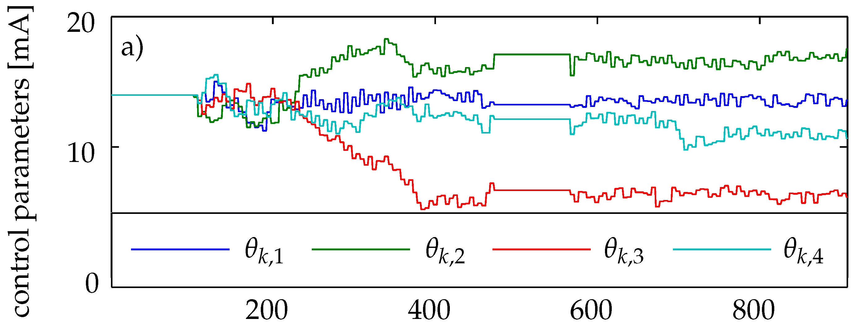
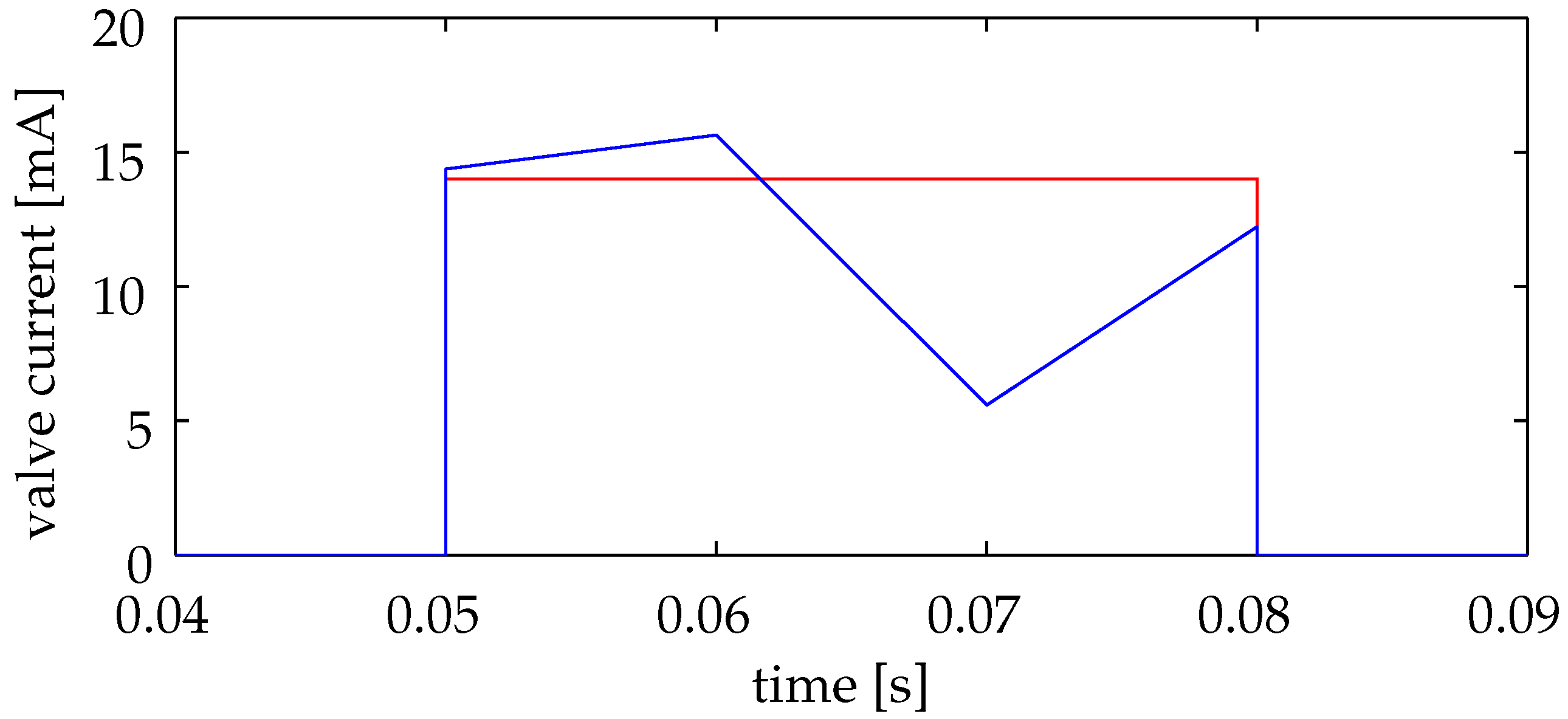
The ESC is an online optimizer that does not require a model of the system to be optimized. This means that during the optimization process, the ESC needs to estimate a local approximation of the system by evaluating the measurement information. According to this local, mostly gradient information, the optimizer then changes the input, defined by a set of parameters θ ̲ k , such that a local optimum of an objective function dependent on the system output is found. In this paper, we will refer to a minimum without loss of generality. To guarantee that the ESC is able to converge to the optimum, it is necessary to have a system with a continuously differentiable input–output static map that is bounded. More assumptions need to be fulfilled for the most frequently used classic ESC set-up; for more details see [10,21].
While there exist many modifications to the ESC, all of them can be described with a common structure [11]. In a first step, the output of the system is evaluated to calculate the value of an objective function. This calculated value and the input of the system are used to approximate the first and possibly higher-order derivatives of the objective function with respect to the actuation. In the classic scheme, a set of high- and low-pass filters is employed to estimate the derivatives. These derivatives are then used by an optimization algorithm to modify the system input in the direction of the optimum. To estimate the derivatives, it is necessary that the input signal to the system is perturbed. In this paper, a modified ESC set-up is proposed. A schematic representation is shown in Figure 5. Details will be given below.
Applying this concept to an SEC where we need to achieve a homogeneous auto-ignition means that the fuel has to be injected into the combustion tube such that it ignites all along the tube at the same time. From the averaged ignition timings, which are detected by the five photodiodes (see Section 2.2), the variance in between the photodiodes is calculated and chosen as the objective function for the ESC that shall be minimized. A value of 0 for the variance would indicate a completely homogeneous SEC. Additionally, a fixed desired reference ignition time r is provided. As deviations from this reference ignition time are penalized, a homogeneous ignition at t = r would yield the lowest objective value. The weighting parameter of the absolute ignition time was set to a small value, W r = 0.0125 , to keep the focus on the homogeneous ignition. In a first step, averaged ignition times t i g n , k ( x q ) are calculated for the last five ignition cycles j = 1 , , 5 for all measurement positions x q , discarding two outliers:
t i g n , k ( x q ) = 1 3 j = 1 5 t ˜ i g n , k , j ( x q ) min j = 1 5 t ˜ i g n , k , j ( x q ) max j = 1 5 t ˜ i g n , k , j ( x q ) .
For all cycles of the k-th iteration, the same plant input u ̲ k = f ( θ ̲ k ) is used. With this data, the objective function J k is determined.
J k = 1 4 q = 1 5 t i g n , k ( x q ) t ¯ i g n , k 2 + W r ( t ¯ i g n , k r ) 2 t ¯ i g n , k = 1 5 q = 1 5 t i g n , k ( x q ) .
The only input value that the ESC is allowed to adjust is the control current of the proportional valve during the injection time. To parametrize the injection profile for the k-th group of a set of five cycles, a piecewise linear function is chosen; see Figure 4. The profile of the five consecutive filling processes in the k-th iteration is defined by a set of interpolation points. To respect real-time requirements, four interpolation points are used in this study. They are concatenated in the vector θ ̲ k = ( θ k , 1 , , θ k , 4 ) . Between these equidistant interpolation points, the injection profile is interpolated linearly (see Figure 4 and Figure 5):
u ̲ k = f ( θ ̲ k ) = u ( t f , θ ̲ k ) u ( t f + Δ t , θ ̲ k ) u ( t f + ( n 1 ) · Δ t , θ ̲ k ) ,
with
u ( t , θ ̲ k ) = θ k , m + ( θ k , m + 1 θ k , m ) 3 ( t t f ) t A t f + 1 m , m 1 3 | t f + ( m 1 ) t A t f 3 t < t f + m t A t f 3
n = t A t f Δ t ,
where u ̲ k is the discrete injection profile, Δ t = 0.0001 s is the sampling interval, and t f and t A are the starting point and the end point of the filling process, respectively.
All combustion cycles in the present set-up are mostly independent from each other. Only the temperature in the tube will depend on previous combustions and influence the ignition delays of subsequent ignitions. This temperature distribution in the tube will change slowly from one ignition cycle to the next and is considered to be a disturbance which has to be handled by the controller.
For each set of five filling processes with the injection profile u ̲ k , the measurements are evaluated by the objective function J k . To obtain information about the local dependency of J on θ ̲ , we propose to fit a multidimensional parabola based on all measurements up to the k-th filling process. To this end, at iteration k, every group of five cycles is approximated by
J ^ i = θ ̲ i A k θ ̲ i + b ̲ k θ ̲ i + c k , i = 1 , , k ,
where A k , b ̲ k , and c k are the as yet unknown Hessian matrix, gradient, and constant offset, respectively. As this equation is linear regarding the unknown entries of A k , and b ̲ k , they can be collected in the vector Φ ̲ ^ k . Equation (6) can then be formally rewritten in the form
J ^ i = x ̲ i Φ ^ ̲ k , i = 1 , , k ,
with x ̲ i being a vector build up from θ ̲ i . Combining Equation (7) for all iterations up to the recent cycle k of five consecutive filling processes in a matrix equation, we obtain
J ^ 1 J ^ k = J ̲ ^ k = X k Φ ^ ̲ k = x ̲ 1 x ̲ k Φ ^ ̲ k .
To estimate Φ ^ ̲ k , we use the least-squares algorithm, which minimizes the squared deviation between the cost function and the estimated parabola:
min Φ ^ ̲ k ( J ̲ k X k Φ ^ ̲ k ) W ( J ̲ k X k Φ ^ ̲ k ) ,
where J ̲ k contains the experimentally obtained objective values from k consecutive iterations. The well-known solution is given by
Φ ^ ̲ k = ( X k W X k ) 1 X k W J ̲ k = : P k X k W J ̲ k ,
with W being a weighting matrix. To emphasize the most recent measurements, older measurements are associated with an exponentially decreasing weight λ. By decreasing the value of λ, it is possible to further limit the influence of old values.
W = λ k 1 0 λ 0 1
To reduce the computational effort, the least-squares problem is solved using a recursive solution of this problem given in Equations (12)–(14). P 0 has to be initialized with high values to account for missing system information in the beginning [22].
γ ̲ k = [ x ̲ k + 1 P k x ̲ k + 1 + λ ] 1 P k x ̲ k + 1
Φ ^ ̲ k + 1 = Φ ^ ̲ k + γ ̲ k [ J k + 1 x ̲ k + 1 Φ ^ ̲ k ]
P k + 1 = λ 1 [ I γ k x ̲ k + 1 ] P k
From the fitted parameters Φ ^ ̲ k of the multidimensional parabola, the gradient and curvature at the current actuation parameter θ ̲ k can be recalculated according to Equation (6). Whenever the fitted parabola is positive definite, the proposed optimization algorithm calculates a Newton step. Therefore, the actuation parameters for the next injection process will be set to the minimum of the identified parabola whenever it is in range of the allowed step size; see below. If the Hessian matrix is not positive definite, the algorithm performs gradient steps with a step size σ θ .
θ ˜ ̲ k + 1 = 0.5 A k 1 b ̲ k , A k > 0 θ ^ ̲ k + σ θ ( 2 A k θ ^ ̲ k + b ̲ K ) , otherwise
Here, θ ^ ̲ k is the unperturbed control parameter of the last iteration, which differs from θ ˜ ̲ k calculated by Equation (15) in the last iteration due to its compliance to the maximum step size θ m a x . Whenever the maximum step size is exceeded, the step size will be set to θ m a x , while the direction of the optimization step is kept constant.
θ ^ ̲ k + 1 = θ ^ ̲ k + ( θ ˜ ̲ k + 1 θ ^ ̲ k ) θ m a x | | θ ˜ ̲ k + 1 θ ^ ̲ k | | 2 , | | θ ˜ ̲ k + 1 θ ^ ̲ k | | 2 θ m a x θ ˜ ̲ k + 1 , otherwise
This last step is necessary for stability reasons, as huge Newton steps might result for an ill-conditioned matrix A .
As for every ESC, a perturbation needs to be applied to the actuation parameter θ ^ ̲ k + 1 . Here, a vector θ ̲ p e r t , k with uniformly distributed random entries in a range between [ d , d ] is added to the calculated θ ̲ ^ k + 1 ; see Figure 5. Because the task of the ESC is not just to find an optimal control profile but also to keep track of it, the amplitude of the pertubation is kept constant to allow for a detection of disturbances at all times. For the application of the SEC, we chose the following values for the tuning parameters: d = 0.5 mA , σ θ = 40 A 2 s 2 , λ = 0.95 , and θ m a x = 1 mA.

3. Results

For the ignition tests with the described set-up, we performed 1000 combustion cycles. However, 9% of the ignitions could not be evaluated properly because not all the photodiodes detected a signal higher than the defined threshold. With the used data acquisition system, it was not possible to store all the data at once. For this reason, the test series had to be paused after 500 cycles. During such a pause, the fuel lines close to the tube are heated up, which yields much lower ignition delays when part of this fuel is injected at the beginning of the next batch of cycles. To avoid interfering with the control algorithm after the pause, 100 filling combustion cycles were carried out with a cycle invariant injection profile. The obtained measurement data was not considered by the ESC. For every single combustion cycle, the timings for the filling and purging of the tube were set to t f = 0.05 s, t A = 0.08 s, t B = 0.58 s, and t E = 0.75 s. The desired reference ignition time r was chosen as 0.25 s such that the resulting range of desired ignition delays was centered inside the limits adjustable by changing the fuel concentration. The injected fuel trajectory was modified every five successful ignitions, according to the control law of the described ESC algorithm. The test series was started with a constant control value applied to the valve of 14 mA. This corresponds to a rich fuel–air mixture.
In Figure 6, the change of the input parameters θ ̲ k , the detected ignition times, and the control error are shown as a function of the iterations. The ESC is set active after 100 iterations. It starts changing the control trajectory such that the control error decreases. The control error is calculated as the variance of the averaged ignition times of five ignitions, as explained in Section 2.2, and also takes the deviation from the desired ignition time into consideration according to Equation (2). However, for the homogeneity of an ignition, the variance of the ignition times is the best measure and is therefore also included in the diagram for every single ignition. Until the 360th iteration, the ignition always takes place at a location far downstream in the tube and is detected by the fifth photodiode first. Due to an increase in the amount of fuel injected in the beginning of the filling process and less fuel injected afterwards (see Figure 7), the ignition at the location of the fifth photodiode can be delayed. From the 360th ignition on, a quite homogeneous ignition is obtained. After achieving a homogeneous ignition, the controller is also able to adjust the ignition time towards the desired value; see Figure 6 (at around 400 iterations). From this point of time, the control trajectory is only changed slightly, which indicates that a local optimum was found by the controller. In Figure 7, the detected ignition times for a constant injection, as conducted in the beginning of the experiment, and for four consecutive injections with the converged control trajectory after 400 iterations are shown. It can be seen that the converged control trajectory found by the ESC yields significantly more homogeneous ignitions necessary for an SEC. However, among the four ignitions with the same filling profile, there is still a high deviation in the ignition times from one cycle to another. This indicates that the system behavior changes from one cycle to the next so that the ESC has no chance to further increase the quality of the SEC just using information from past combustion cycles. A high deviation between consecutive ignitions can also be observed for the pressure readings. On average, though, the pressure rise, due to the combustion, increased due to the higher homogeneity of the ignition process, as depicted in Figure 6. The highest pressure rise measured for one ignition was 0.36 bar, which was achieved for an ignition taking place within less than 2 ms.

4. Conclusions

In this paper, a model-free control method is presented to optimize a control input for iterative tasks where virtually no system information is available. The considered control addresses the essential challenge of SEC—the homogeneous auto-ignition of the fuel. The effectiveness of the developed ESC algorithm is demonstrated with an atmospheric test rig, which was designed to study the auto-ignition behavior at a firing frequency of 4 3 Hz. A fast proportional valve was used to adjust the amount of fuel injected into the combustion tube. Using an optical measuring technique, the ignition times were detected. The variance of these ignition times, which provides a good measure for the homogeneity of the self-ignition, was used as a control target. As the chemical processes are hard to model with respect to a real-time application and are very sensitive to unmeasured quantities, such as the pressure and temperature distribution inside the combustion tube, a model-free approach was chosen. The applied ESC was able to minimize the variance using an online optimization. The first and second derivatives of the objective function were estimated by a recursive least-squares algorithm and used to perform Newton steps. However, with this method, only a local minimum can be guaranteed. Although the experiments showed that the time span of a completed ignition process could be significantly decreased below 2 ms, at the atmospheric conditions the resulting pressure rise is still not as high as would be expected for a perfect SEC. However, for combustions performed under elevated pressure, which are planned for the near future, the ignition delay will be significantly lower. For the same mixing quality, this would reduce the duration of the ignition process accordingly. As a result, the applied mixing control method presents a powerful tool to realize an SEC at relevant pressure levels.

Acknowledgments

The authors gratefully acknowledge the support of the Deutsche Forschungsgemeinschaft (DFG) as part of collaborative research center CRC 1029 "Substantial efficiency increase in gas turbines through direct use of coupled unsteady combustion and flow dynamics".

Author Contributions

Jan-Simon Schäpel built the controller, ran the experiments, and wrote the paper, supervised by Rudibert King. Thoralf Reichel was responsible for the experimental set-up. Rupert Klein and Christian Oliver Paschereit developed the concept of an SEC.

Conflicts of Interest

The authors declare no conflict of interest.

Abbreviations

The following abbreviations are used in this manuscript:
aCVC
approximate constant volume combustion
ESC
extremum seeking controller
PDE
pulsed detonation engine
RDE
rotating detonation engine
SEC
shockless explosion combustion

References

  1. Putnam, A.; Belles, F.; Kentfield, J. Pulse combustion. Prog. Energy Combust. Sci. 1986, 12, 43–79. [Google Scholar] [CrossRef]
  2. Roy, G.; Frolov, S.; Borisov, A.; Netzer, D. Pulse detonation propulsion: challenges, current status, and future perspective. Prog. Energy Combust. Sci. 2004, 30, 545–672. [Google Scholar] [CrossRef]
  3. Lu, F.K.; Braun, E.M. Rotating detonation wave propulsion: experimental challenges, modeling, and engine concepts. J. Propuls. Power 2014, 30, 1125–1142. [Google Scholar] [CrossRef]
  4. Bobusch, B.C.; Berndt, P.; Paschereit, C.O.; Klein, R. Shockless Explosion Combustion: An Innovative Way of Efficient Constant Volume Combustion in Gas Turbines. Combust. Sci. Technol. 2014, 186, 1680–1689. [Google Scholar] [CrossRef] [Green Version]
  5. Bobusch, B.C. Fluidic Devices for Realizing the Shockless Explosion Combustion Process. Ph.D. Thesis, Technische Universität Berlin, Berlin, Germany, 2015. [Google Scholar]
  6. Berndt, P.; Klein, R.; Paschereit, C.O. A Kinetics Model for the Shockless Explosion Combustion. In Proceedings of the ASME Turbo Expo 2016: Turbomachinery Technical Conference and Exposition, Seoul, Korea, 13–17 June 2016; Volume 4B.
  7. Reichel, T.G.; Schäpel, J.S.; Bobusch, B.C.; Klein, R.; King, R.; Paschereit, C.O. Shockless Explosion Combustion: Experimental Investigation of a New Approximate Constant Volume Combustion Process. J. Eng. Gas Turbines Power 2016, 139, 021504–021510. [Google Scholar] [CrossRef]
  8. Tan, Y.; Moase, W.; Manzie, C.; Nesic, D.; Mareels, I. Extremum seeking from 1922 to 2010. In Proceedings of the 29th Chinese Control Conference, China, Beijing, 28–31 July 2010.
  9. Krstic, M.; Wang, H.H. Design and Stability Analysis of Extremum Seeking Feedback for General Nonlinear Systems. In Proceedings of the Conference on Decision & Control, San Diego, CA, USA, 10–12 December 1997; pp. 1743–1748.
  10. Tan, Y.; Nesic, D.; Mareels, I. On non-local stability properties of extremum seeking control. Automatica 2006, 42, 889–903. [Google Scholar] [CrossRef]
  11. Nesic, D.; Tan, Y.; Manzie, C.; Mohammadi, A.; Moase, W. A unifying framework for analysis and design of extremum seeking controllers. In Proceedings of the IEEE Chinese Control and Decision Conference, Taiyuan, China, 23–25 May 2012; pp. 4274–4285.
  12. Krstic, M. Performance improvement and limitations in extremum seeking control. Syst. Control Lett. 2000, 39, 313–326. [Google Scholar] [CrossRef]
  13. Henning, L.; Becker, R.; Feuerbach, G.; Muminovic, R.; King, R.; Brunn, A.; Nitsche, W. Extensions of adaptive slope-seeking for active flow control. Proc. Inst. Mech. Eng. Part I J. Syst. Control Eng. 2008, 222, 309–322. [Google Scholar] [CrossRef]
  14. Gelbert, G.; Moeck, J.P.; Paschereit, C.O.; King, R. Advanced algorithms for gradient estimation in one- and two-parameter extremum seeking controllers. J. Process Control 2012, 22, 700–709. [Google Scholar] [CrossRef]
  15. Moase, W.H.; Manzie, C.; Brear, M.J. Newton-Like Extremum-Seeking for the Control of Thermoacoustic Instability. IEEE Trans. Autom. Control 2010, 55, 2094–2105. [Google Scholar] [CrossRef]
  16. Schäpel, J.S.; King, R.; Bobusch, B.; Moeck, J.; Paschereit, C.O. Adaptive Control of Mixture Profiles for a Combustion Tube. In Proceedings of the ASME Turbo Expo 2015: Turbine Technical Conference and Exposition, Montréal, QC, Canada, 15–19 June 2015. GT2015-42027.
  17. Khong, S.Z.; Nesic, D.; Krstic, M. Iterative learning control based on extremum seeking. Automatica 2016, 66, 238–245. [Google Scholar] [CrossRef]
  18. Tan, Y.; Nesic, D.; Mareels, I. On the choice of dither in extremum seeking systems: A case study. Automatica 2008, 44, 1446–1450. [Google Scholar] [CrossRef]
  19. Liu, S.J.; Krstic, M. Stochastic Averaging in Continuous Time and Its Applications to Extremum Seeking. IEEE Trans. Autom. Control 2010, 55, 2235–2250. [Google Scholar] [CrossRef]
  20. Bobusch, B.C.; Berndt, P.; Paschereit, C.O.; Klein, R. Investigation of fluidic devices for mixing enhancement for the shockless explosion combustion process. In Active Flow and Combustion Control 2014; King, R., Ed.; Springer International Publishing: Cham, Switzerland, 2015; pp. 281–297. [Google Scholar]
  21. Kristic, M.; Wang, H.H. Stability of extremum seeking feedback for general nonlinear dynamic systems. Automatica 2000, 36, 595–601. [Google Scholar] [CrossRef]
  22. Iserman, R.; Münchhof, M. Identification of Dynamic Systems; Springer: Berlin/Heidelberg, Germany, 2011. [Google Scholar]
Figure 1. Sketch of the effect of equivalence ratio stratification on ignition delay time distribution (for details see text). (a) constant fuel profile (b) stratified fuel profile.
Processes 04 00048 g001
Figure 2. Schematic of the atmospheric SEC test rig.
Processes 04 00048 g002
Figure 3. Section view of the injection geometry and combustion tube with sensors.
Processes 04 00048 g003
Figure 4. Example of one filling cycle showing the timings for the fuel and air injection and schematic photodiode signals.
Processes 04 00048 g004
Figure 5. Schematic representation of the ESC used in this paper.
Processes 04 00048 g005
Figure 6. Experiment with 900 successful combustion cycles (9% of the ignitions are misfiring and not included in the diagram for clarity). (a) Control parameters defining the control profile of the fuel valve; (b) Ignition times detected by the photodiodes; (c) Homogeneity of the ignition evaluated by the variance and by the control error that is calculated for every five consecutive ignitions when the controller is active; (d) Maximum pressure increase due to the ignition.
Processes 04 00048 g006aProcesses 04 00048 g006b
Figure 7. Example of five time-resolved combustion processes. Red: Injection profile and detected ignition times with initialized control trajectory; Blue: Injection profile and detected ignition times with converged control trajectory (ignition number 401–404). The four consecutive shots have the same injection profile. Their individual ignition timings are depicted with different markers.
Processes 04 00048 g007aProcesses 04 00048 g007b

