Abstract
This paper reports the findings of a FP7 project (DEMCAMER) that developed materials (catalysts and membranes) and new processes for four industrially relevant reaction processes. In this project, active, stable, and selective catalysts were developed for the reaction systems of interest and their production scaled up to kg scale (TRL5 (TRL: Technology Readiness Level)). Simultaneously, new membranes for gas separation were developed; in particular, dense supported thin palladium-based membranes for hydrogen separation from reactive mixtures. These membranes were successfully scaled up to TRL4 and used in various lab-scale reactors for water gas shift (WGS), using both packed bed and fluidized bed reactors, and Fischer-Tropsch (FTS) using packed bed reactors and in prototype reactors for WGS and FTS. Mixed ionic-electronic conducting membranes in capillary form were also developed for high temperature oxygen separation from air. These membranes can be used for both Autothermal Reforming (ATR) and Oxidative Coupling of Methane (OCM) reaction systems to increase the efficiency and the yield of the processes. The production of these membranes was scaled up to TRL3–4. The project also developed adequate sealing techniques to be able to integrate the different membranes in lab-scale and prototype reactors.
1. Introduction
Global warming and fossil fuels scarcity necessitate the transformation of traditional processes towards more sustainable and efficient processes for both energy conversion and chemical transformations. A boost in efficiency for reactive systems can be achieved via the so-called Process Intensification (PI), which is defined as “any chemical engineering development that leads to a substantially smaller, cleaner, safer, and more energy efficient technology” [1]. The need for more efficient processes, including further flexible engineering designs and, at the same time, increasing the safety and environmental impact of these processes, is pushing the industry to carry out novel research in this field. The chemistry and related sectors have already recognized the benefits of PI and estimate a potential for energy saving of about 1000 kilo tonnes of oil equivalent (ktoe) per year using these processes.
Nowadays, the main activities regarding PI are related to the development of novel technologies with high efficiency as well as accomplishing a reduction in CO2 emissions to the atmosphere, thus achieving a large positive impact as compared to benchmark technologies [2]. Within the chemical engineering framework, the development of more active catalysts, more efficient contactors, heat exchangers or gas separation units are of interest as these technologies are involved in most chemical processes. The technology of membrane reactors has been recently developed and has demonstrated a high degree of process intensification where the combination of a membrane based separation and a catalytic chemical reaction take place in one unit [3,4,5,6,7,8,9]. Membranes can be used in membrane reactors for either selective gas separation from the reaction environment or selective gas feeding into the reaction system [3]. In equilibrium limited reaction systems such as in fuel reforming or dehydrogenations, the selective separation of a product of the reaction (i.e., H2), leads to a fuel conversion beyond the value of the thermodynamic equilibrium, thus achieving higher fuel conversions and direct product separation (a separation unit downstream is not required). The other possible configuration is selective gas addition via the membrane. For instance, in autothermal reforming where oxygen is fed together with the fuel, the dosing of oxygen alongside the membrane instead of direct co-feeding leads to an enhancement of the selectivity of products. In general, almost every catalytic industrial process can potentially be enhanced by the introduction of catalytic membranes and membrane reactors instead of the conventional reactors. According to SusChem (European Technology Platform for Sustainable Chemistry, Strategic Research Agenda 2005) more than 80% of the processes in the chemical industry worth approximately €1,500 billion, depend on catalytic technologies, and one of the shorter-term (5–10 years) objectives of this Platform is to “integrate reactor-catalyst-separation design: integration and intensification of processes require the development of new catalytic concepts which break down the current barriers (for example, low flux in catalytic membranes)” [10].
In this work, an overview is presented of the DEMCAMER project, which proposes a solution for many industrial processes that can benefit from membrane reactors: the increase in production rate while maintaining the same product quality as well as reducing both production costs and environmental impact. The objective here is to carry out this action through the implementation of a novel process intensification approach consisting of the combination of reaction and separation in a “Catalytic Membrane Reactor” single unit as is depicted in Figure 1.
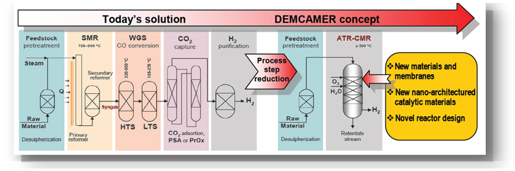
Figure 1.
DEMCAMER project concept summarized for the Autothermal Reforming (ATR) process.
The aim of the DEMCAMER project was to develop innovative multifunctional Catalytic Membrane Reactors (CMR) based on new nano-architectured catalysts and selective membrane materials to improve their performance, cost effectiveness (i.e., reducing the number of steps), and sustainability (lower environmental impact and use of new raw materials) over four selected chemical processes ((Autothermal Reforming (ATR), Fischer-Tropsch (FTS), Water Gas Shift (WGS), and Oxidative Coupling of Methane (OCM)) for pure hydrogen, liquid hydrocarbons, and ethylene production.
The DEMCAMER work plan consisted of activities related to the whole product chain: i.e., development of materials/components (membranes, supports, seals, catalyst...) through integration/validation at lab-scale, until development/validation of four semi-industrial pilot scale CMRs prototypes. Additionally, assessment of environmental, health and safety issues—in relation to the new intensified chemical processes—were also carried out.
For a maximum impact on the European industry this research, covering the complete value chain of catalytic membrane reactors, was carried out with a multidisciplinary and complementary team having the right expertise, including top level European Research Institutes and Universities (8 RES) working together with representative top industries (4 SME and 6 IND) in different sectors (from raw materials to petrochemical end-users).
Figure 2 and Table 1 summarize the four chemical processes addressed by DEMCAMER including the raw materials and products per each targeted reaction. Membranes for the different processes are also indicated in the flow sheet. Both the flow sheet and the table do not take into account previous stages of pre-treatment for the raw materials as this has not been addressed in DEMCAMER.
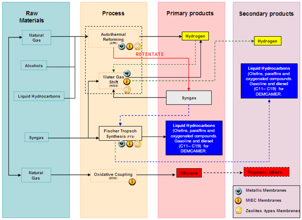
Figure 2.
Flow sheet of the four chemical processes addressed in DEMCAMER.

Table 1.
Raw materials and obtained products per each targeted reaction.
The raw materials for the ATR process could cover a wide range: natural gas, SNG (Synthetic Natural Gas produced from coal, biomass, petroleum coke, or solid waste), alcohols (methanol and ethanol), dimethyl ether (DME), liquid hydrocarbons derived from fossil fuels (gasoline, diesel, naphtha, etc.), biogas, biofuels (biodiesel, bioethanol, etc.). DEMCAMER only addressed natural gas (mainly CH4) as raw material. On the other hand, Syngas could be the raw material for the WGS and the FTS processes. Syngas could be derived from dry, steam, partial oxidation and autothermal reforming processes using natural gas, coal or biomass. Finally, natural gas, SNG or Biomass could be the raw materials in the OCM process but natural gas was the raw material considered in DEMCAMER.
In this project the targeted primary products were H2, liquid hydrocarbons (gasoline/diesel fractions (C11–C20), and ethylene. The definition and identification of the specific industrial requirements for the intensification of each targeted reaction was addressed at the beginning of the project.
The DEMCAMER Project was funded under FP7 Cooperation Specific Programme and Nanotechnologies, Materials and Processes NMP Theme. The Project started on July 1 2011 and it has run for 48 months. In the following, the main results in terms of catalysts, membranes, and membrane reactors are highlighted.
2. Experimental Section
2.1. Catalyst Selection for the Different Processes
Catalysts used in benchmark technologies were developed to maximize the performance of the process. However, the experimental conditions used in benchmark technologies are often far from the conditions needed in membrane reactors, mainly the reaction temperature and reaction mixture/concentrations. In order to maximize the performance of the membrane reactor technologies, improved catalysts were developed for each process in the DEMCAMER project. In this section, the selection of the catalyst used in each process is discussed in more detail.
2.1.1. ATR Catalyst
The integration of the membrane reactor in the ATR system requires the use of a catalyst with extreme thermal stability (structural/morphological resistances) at low oxygen concentrations and high resistance to carbon formation and deactivation by sulfur. Taking into account that ATR catalyst poisoning by sulfur and/or carbon is a structure sensitive reaction, the control of the electronic structure and size of the active metal surfaces was the strategy followed in the development of innovative ATR catalysts with improved catalytic activity and stability. The ATR catalyst developed was designed based on conventional supported catalysts. The optimal selection of the ATR catalyst was performed by carrying out ATR studies varying the composition of the active phase (Ni, Ru, Pt, Pd) [11,12,13], the support (La2O3, CeO2-ZrO2, CeO2-Gd2O3) and the method of preparation (impregnation, sol-gel, etc.).
The optimization of the selected catalyst was done by catalytic screening in the ATR reaction of methane in a 14 mm i.d. quartz fixed-bed reactor with a feed composition of CH4:H2O:O2:He equal to 1:1:0.75:2.5 under atmospheric pressure and temperatures ranging from 650 to 950 °C and inlet gas flow rate of 200 mLN/min. More information on the tests carried out for the selection of the support material and the promoters for the reactions can be found in the works of Ismagilov et al. [14,15]. In order to obtain the desired properties of the catalyst support, a deep characterization of fresh and used samples of all catalytic series prepared was performed, where the main structural and surface characteristics of the catalysts that have strong influence on the ATR catalytic activity and stability were identified. From catalytic screening tests, durability tests, and characterization of ATR catalysts, the optimal composition and preparation method of catalyst was selected, which is based on Ni-Pd catalysts deposited on optimized ceria based support. A description of the preparation method for the final ATR catalyst can be found in [15].
2.1.2. WGS Catalyst
The experimental conditions used in membrane reactors for WGS reaction are very different from those encountered in conventional shift reactors (temperature limit due to membrane stability, low partial pressure of steam and high partial pressure of CO2). This implies that extensive research is needed to develop and improve catalysts with high activity, selectivity, and stability. In the development of WGS catalysts, innovative formulations based on ceria and titania-based platinum catalysts have been studied [16,17].
A conventional preparation method based on controlled impregnation was applied in order to tune both the Pt-support interactions and the type of Pt surface species (small metal clusters, Pt ions and Pt atoms at a metal cluster edge) present on the catalyst surface. Selection of WGS catalysts was carried out from catalytic screening in the WGS reaction at lab-scale in a fixed-bed quartz reactor, which had 9 mm i.d., at atmospheric pressure using 0.1 g of the catalyst (mean particle size of around 225 μm). Experiments were carried out at 400 °C for 20 h with a gas mixture of H2/CO2/CO/H2O/CH4/N2 and spatial volume of 23.230 L∙h−1∙kgcat−1 in order to simulate biogas syngas. A deep characterization of fresh and used samples was also carried out in order to understand the behavior of the catalyst at the reacting conditions. From catalytic WGS screening tests and physico-chemical characterization data, the optimal composition and preparation method of the WGS catalyst was selected. The final generation of WGS catalysts was based on Pt-Re catalysts deposited on an optimized cerium-titanium mixed oxide support. A description of the preparation method used for the catalyst is presented in Villar et al. [18].
2.1.3. FTS Catalyst
The use of membrane reactors for FTS reactions is an attractive option because this approach allows the heat of the reaction to be controlled and enhances the selectivity to long-chain hydrocarbons. Several concepts such as distributed hydrogen feed, water removal, and forced-through flow membrane were assessed using different reactor configurations [19,20]. FTS membrane reactors require the integration of novel catalysts with higher catalytic performances than that of state-of-the-art Co-based catalysts in terms of C5+ productivity [21].
To achieve this objective, different FTS catalyst based on Ru-type were prepared, characterized, and tested as Ru has shown good results for the FTS reaction [22,23]. From catalytic screening FTS tests, durability tests and characterization of catalysts, the optimal composition and preparation method of FTS catalyst was selected (B-Ru/TiO2). The B-doped Ru/TiO2 catalyst (3 wt% Ru) was prepared by incipient wetness impregnation on the support. A detailed procedure is described in [24], as well as the procedure conducted in a fixed bed reactor at temperatures between 250 and 300 °C in order to test the catalytic activity of the prepared FTS catalyst.
2.1.4. OCM Catalyst
The integration of the OCM reactor with mixed ionic-electronic conducting membranes (MIECM) requires a good match between the oxygen permeation rate through the membrane and the OCM reaction rate on the catalyst. Two different types of catalysts have shown promising results for the OCM reaction (La-Sr/CaO and Mn-Na2WO4/SiO2) [25,26,27], and the development of the novel catalyst for OCM was carried out using these two catalysts as reference and adding dopants (Mn and rare earths) and promoters (S, P, Cl) to increase the selectivity to ethylene.
The optimal support type and metal content for Mn-Na2WO4/SiO2 OCM catalysts were first investigated and subsequently the modification of Mn-Na-W/SiO2 material by different promoters as structural and electronic modifying agents was performed. From these results, Mn-La- modified-Mn-Na2WO4/SiO2 OCM catalysts were selected as a more perspective composition. The optimization of preparation techniques (incipient wetness impregnation, mixture slurry method), conditions of impregnation (temperature of impregnating solution), temperature of catalyst calcination (800 °C, 850 °C, 900 °C, 1000 °C) and pretreatment conditions of Mn-Na2WO4/SiO2 catalyst before OCM reaction (700 °C O2/He; 800 °C O2/He; 800 °C He) were also optimized. Finally the designed catalyst for the OCM process was prepared by sequential incipient wetness impregnation using commercial SiO2 as support. A description of the preparation method is defined in the work by Vamvakeros et al. [28], where the final composition of the catalyst is 2%Mn-1.6%Na-3.1%W/SiO2.
2.2. Membranes Developed within the DEMCAMER Project
As shown in Figure 2, three different types of membranes can be integrated in the different processes developed within the project: Mixed Ion-Electron Conducting (MIEC) membranes, zeolite membranes, and metal based membranes for hydrogen production. The development of the materials for the MIEC membranes, zeolite membranes, metal based membranes (i.e., ceramic supports, metallic supports, interdiffusion layers (for metallic membranes), and selection of improved materials for the target application are of interest for a proper development of the integrated processes towards prototype reactors. A description and discussion of the prepared membranes within the DEMCAMER project are presented in this section.
2.2.1. MIEC Membranes
These type of membranes, with the characteristic rich defect chemistry, oxygen vacancies and electronic conductivity, have been used for many years for oxygen separation (although not yet at industrial scale) [29,30,31,32]. These membranes are normally meant for oxygen separation, but they can also be adjusted to H2 separation [33]. However, due to the low H2 permeance through the membranes compared to other metal-based membranes for H2 separation, MIEC membranes are mostly developed for oxygen separation. In particular, processes demanding oxygen at high temperatures like the ATR reaction can benefit by the selective feeding of oxygen alongside the MIEC membranes, thus achieving a better control of the reaction and enhancing selectivity to products. Within the DEMCAMER project, different objectives concerning MIEC membranes were proposed in the beginning, such as the screening production of feedstock perovskite powders for the development of hollow fibers for O2 and H2 permeation and setting of protocols for large-scale production of the selected perovskite material.
The MIEC hollow fibers developed in the project were prepared by spinning and phase inversion methods and subsequently tested for characterization under reacting conditions. Perovskite membranes were prepared at the Flemish Institute for Technological Research (VITO) in the form of capillaries from Ba0.5Sr0.5Co0.8Fe0.2O3-δ (BSCF) and La0.6Sr0.4Co0.2Fe0.8O3-δ (LSCF) mixed ionic-electronic conducting powders. A detailed description on the procedure used for the preparation method is presented in the work by Buysse et al. [34]. The prepared membranes were characterized using different techniques. A snapshot of the prepared MIEC membranes is depicted in Figure 3.
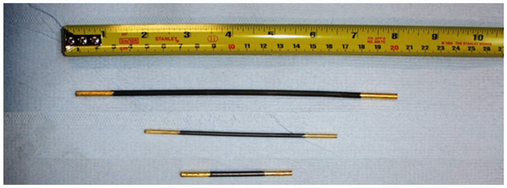
Figure 3.
Snapshot of perovskite membranes prepared for the DEMCAMER project already sealed with a gold layer [35].
One of the main barriers of perovskite membranes for industrial application is related to the sealing mechanism and connection to the reactor. In this project a new sealing method was developed for the prepared membranes in order to allow the use of MIEC membranes in reacting conditions for selective O2 feeding. This sealing consists of an inert gold layer applied between the membrane and the glass sealant, which assures gas-tight conditions for more than 600 h. A detailed picture of the sealing is depicted in Figure 4, where the gold layer over the perovskite membrane can be observed. The general description of the sealing procedure was reported in the work by di Felice et al. [35].
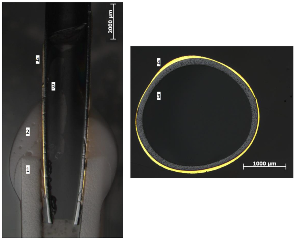
Figure 4.
Optical photographs of cross section of Mixed Ion-Electron Conducting (MIEC) membranes sealed with gold [35]. (1) Al2O3 tubes; (2) glass seal; (3) membrane wall; (4) gold coating.
Based on the permeation results after membrane sealing and experimental permeation tests at high temperature, first the prepared MIEC membranes wereen tested for long term stability. For ATR and OCM processes more than 80 MIEC membranes in lengths of 10 cm and more than 40 in lengths of 5 cm were produced and made available. However, once they were sealed, they did not have sufficient mechanical integrity to withstand mechanical stresses during integration in the reactor prototype assemblies.
2.2.2. Metal Based Membranes for H2 Production
Many efforts have been put into the development of Pd-based membranes for selective H2 separation in the literature in order to overcome the barrier of large-scale industrial applications [3]. In general, membrane stability over a long period of time with sufficient perm-selectivity is the key parameter which would make these membranes interesting for the industrial scale. The selection of the proper support where Pd-layers are deposited becomes important in order to achieve this interesting goal. Normally ceramic supports show improved H2 diffusion through the support, thus enhancing permeations through the membranes. However, the mechanical strength of these supports is much lower compared to porous metallic supports. Therefore thicker ceramic supports are needed. Overall, the use of ceramic supports implies that less surface area is needed in order to achieve high H2 fluxes. On the other hand, metallic supported membranes have shown very good stabilities over time with outstanding selectivities [36,37]. However, the permeance values measured are in general 3–4 times lower than ceramic supported membranes, thus longer membranes should be prepared in order to achieve the desired targets of H2 permeation with the corresponding economical penalty for the process. As it can be concluded, there is not yet an ideal membrane for H2 separation and a compromise between durability and functionality should still be achieved. Both metallic and ceramic supported Pd-membranes have been used in the literature in fixed bed and fluidized bed configurations showing high resistances to erosion. Therefore the stability under reacting conditions has been assessed. However, the main limiting issue regarding the ceramic supported membranes is the sealing between the ceramic tubes and metallic tubes for the coupling in the membrane reactor. This fact was a main point of interest in the development of improved Pd-based membranes in the DEMCAMER project.
Based on the enhancement in permeances associated to ceramic supports compared to metallic based supports, Pd-based ceramic supported membranes were developed for the lab-scale and prototype reactors using thicker wall supports in order to increase the mechanical properties (a figure with metallic and ceramic supports is depicted in Figure 5).
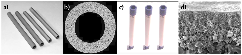
Figure 5.
(a) Metal porous supports; (b) Cross section of a metal porous support; (c) Ceramic porous support (50 cm long) and (d) Cross section of the external side of the ceramic porous support showing the 100 nm pore side Al2O3 top layer).
Pd-Ag membranes supported onto Al2O3 porous ceramic support were developed by simultaneous electroless plating. Single gas permeation tests showed H2 permeances (>2.6 × 10⁻⁶ mol∙m−2∙s−1∙Pa−1) and selectivities (H2/N2 > 10,000) well above the targets of the project. Deep information and characterization of these membranes can be found in the work of Fernandez et al. [38,39]. Besides the membranes for the lab-scale tests (Figure 6), 33 membranes of 22–23 cm long (OD 10 mm–ID 7 mm) were delivered for the WGS prototype. In addition, 5 Pd-Ag membranes of 15 cm long (OD 10 mm–ID 7 mm) with higher Ag content were developed by a two-step process: simultaneous electroless plating of Pd-Ag and direct Ag deposition by PVD. These membranes have been delivered for testing the FTS H2 distributed feeding concept at small pilot scale.
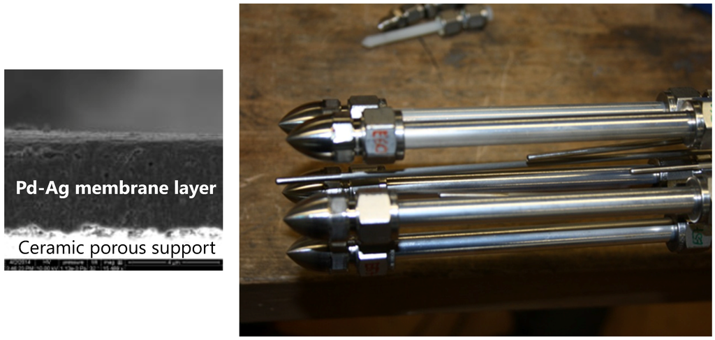
Figure 6.
(Left) Cross section of a Pd-Ag membrane; (Right) Pd-Ag membranes to be integrated in the lab-scale reactor.
2.3. Lab Scale Reactors Constructed for the Different Processes
Once the catalysts and membranes were carefully selected and developed showing promising results, both were combined in modules for lab scale testing under reacting conditions for all processes investigated in the DEMCAMER project. In this section the setups constructed to achieve this objective are presented.
2.3.1. Lab Scale ATR Reactor
A new lab-scale membrane reactor was designed and built in order to study the ATR reaction. The reactor can accommodate 4 MIEC membranes with diameter of up to 4 mm and 10 cm length, and two porous membranes for steam addition. A schematic view of the new reactor can be seen in Figure 7.
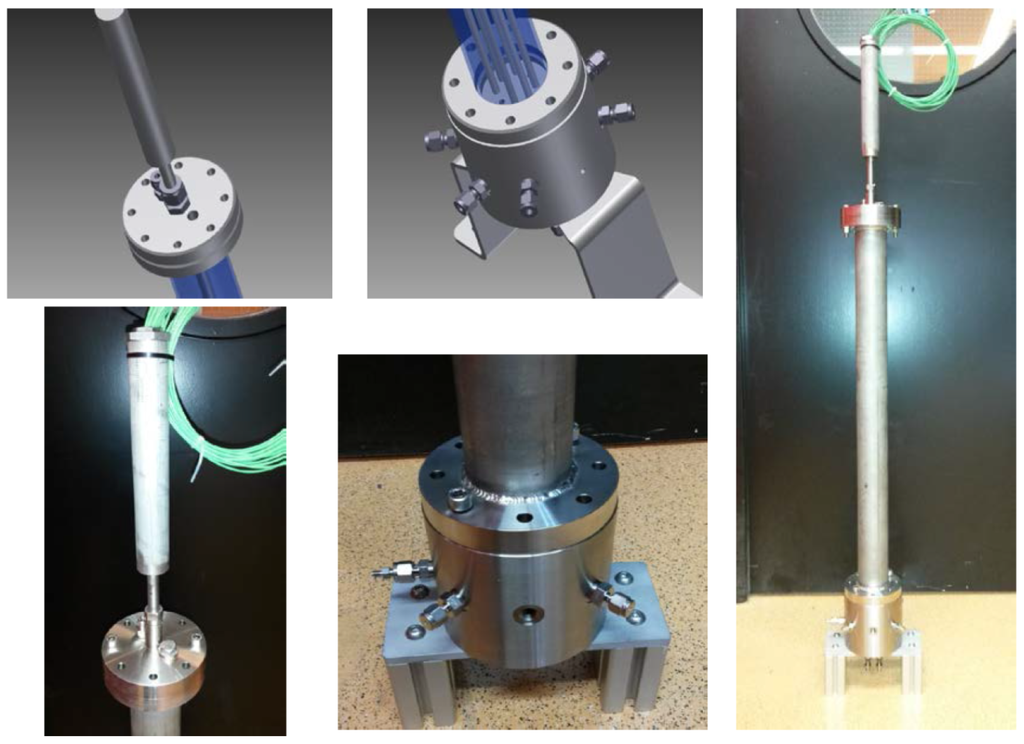
Figure 7.
Parts of the new reactor as designed and built and final reactor assembled.
2.3.2. Lab Scale WGS Reactor
Two different bed configurations were selected for lab scale demonstration of the WGS reaction in membrane reactors. The first configuration is the packed bed membrane reactor, which allows for easier coupling of the membrane in the reactor, but at the same time lacks freedom in the arrangement of the membrane. The second configuration is the fluidized bed membrane reactor, where the developed membranes should withstand erosion from the particles.
The WGS packed bed membrane reactor setup was designed and built for hosting Pd-based membranes produced in the DEMCAMER project as well as commercial ones. In order to obtain a comparison in the WGS performance, different catalyst-membrane combinations were selected: (1) Pd-Ag supported membrane with the catalyst developed in the project; (2) Pd-Ag supported membrane developed in DEMCAMER with a commercial catalyst and (3) Pd-Ag commercial membrane together with the catalyst developed in the project [40].
The experimental apparatus used for this investigation is shown in Figure 8. The reactor was placed inside an electric furnace to keep the desired temperature. Three mass flow controllers were used to feed gas mixture into the module, whereas an HPLC pump fed liquid water directly vaporized inside the furnace. The outlet stream flow rates were measured with two bubble soap flow-meters. The feed pressure was regulated by means of a back pressure controller placed on the retentate line, whereas the permeate was kept at atmospheric pressure. The retentate and permeate streams compositions were analyzed by means of a gas chromatograph (Agilent 7890N) with two parallel analytical lines, allowing retentate and permeate streams analyses at the same time. The temperature was measured by using a thermocouple positioned in the middle of the reactor shell (inside the catalyst bed).
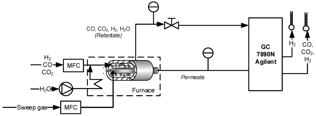
Figure 8.
Scheme of the packed bed membrane reactor set up used for the Water Gas Shift (WGS) lab scale demonstration.
The WGS fluidized bed membrane reactor was performed in an equipment that can be used for testing the permeation properties of the membranes using single gases, simulated mixtures of gases and also in reactive conditions with fluidized catalyst. A shell-and-tube module configuration was constructed centered in an oven with three zone temperature controllers. The reactor is 10 cm i.d. and five ceramic supported Pd-based membranes can be immersed in the bed. The feed flow rate was controlled by digital mass flow controllers and the steam by a Controlled Evaporation and Mixing (CEM) system (Bronkhorst, Frankfurt, Germany). The pressure in the reactor was controlled with a back-pressure regulator after steam condensation. The flow rate at the permeate and retentate streams was monitored by Brooks mass flow meters. To enhance the driving force for hydrogen permeation, the test rig was equipped with a vacuum pump for hydrogen (ATEX certified). The PID for the Reforming Test Setup is shown in Figure 9.

Figure 9.
PID of the fluidized bed membrane reactor used for the WGS lab scale demonstration [37].
For the two reactor configurations, long-term stability tests at WGS operating conditions were carried out in order to demonstrate the WGS-MR concept.
2.3.3. Lab Scale FTS Reactor
The evaluation of the FTS process at lab scale was carried out in a packed bed membrane reactor with H2-distributed feeding alongside the ceramic supported Pd-Ag membranes developed within the project. These membranes consist of a Pd and Ag layer (≈3.2 μm thicknesses) with a total length of 6 cm and deposited onto alumina tubes with OD and ID of 10 and 7 mm. The FTS catalyst used in all experiments with PBMR was the “final generation” FTS catalyst Ru-1B-Ti. A scheme of the setup used is depicted in Figure 10.
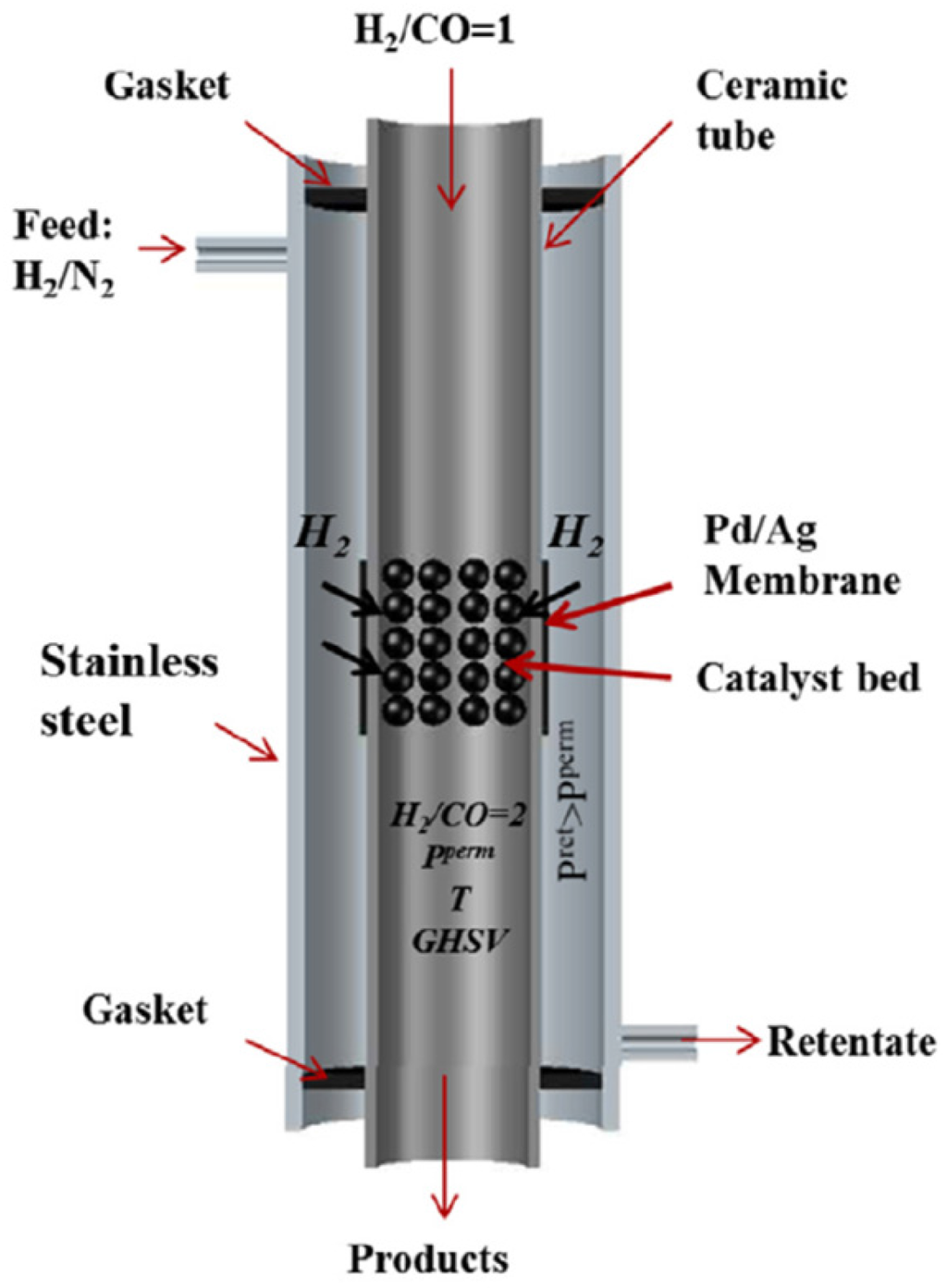
Figure 10.
Schematic drawing of the Fischer-Tropsch Packed-Bed Membrane Reactor (FTS PB-MR) used for lab-scale demonstration with H2 distribution into the bed via Pd-Ag membrane [24].
Experiments in the lab scale PB-MR were conducted at temperatures ranging from 250 to 280 °C and 10 bar pressure using a GHVS of 7500 mLfeed/gcat/h. In the packed bed configuration, the catalyst was placed inside the alumina membrane and located in the region of the Pd-Ag membrane in order to allow distributive feeding of H2. The overall syngas ratio H2/CO is obtained by feeding a ratio H2/CO equal to 1 from the inside of the alumina tube and diluted H2 from the shell part as depicted in the figure.
2.3.4. Lab Scale OCM Reactor
The OCM process was investigated in a packed bed membrane reactor system. Three different packing configurations were considered for the lab-scale investigation. In these configurations, the catalyst developed for the OCM process is packed either inside or outside the membrane. For both cases, the whole system could be integrated in a quartz tube in order to avoid gas leakages from the reactor. The final configuration (as depicted in Figure 11) corresponds to a packed bed membrane reactor where the catalyst is packed inside the MIEC membrane.
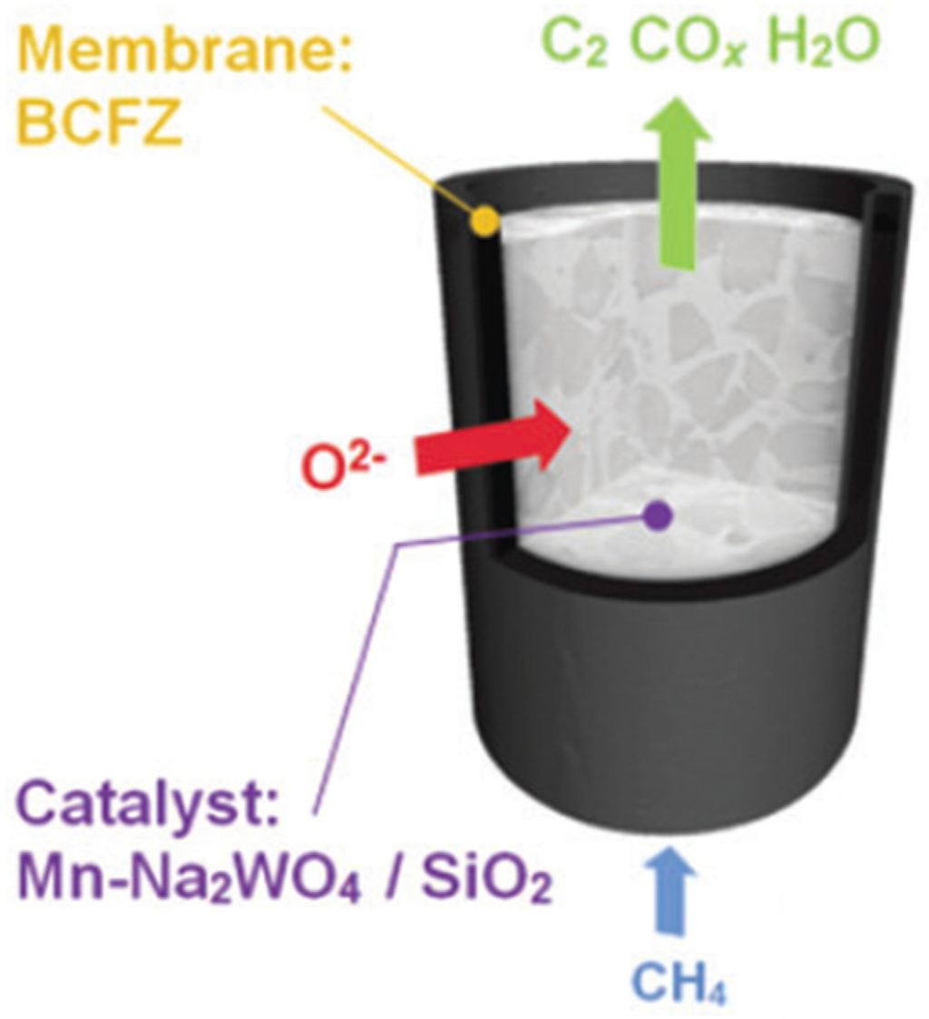
Figure 11.
Schematic representation of the lab-scale Oxidative Coupling of Methane (OCM) packed bed membrane reactor constructed in the project using the developed catalyst and Mixed Ion-Electron Conducting (MIEC) membranes.
The 2%Mn-1.6Na-3.1%W/SiO2 catalyst was confined inside a BaCoxFeyZrzO3-δ (BCFZ) hollow fiber membrane with an inner diameter of 2.4 mm and wall thickness of 180 μm. Glass wool was used in order to hold the catalyst inside the membrane. In this configuration, diluted methane (in He) was fed from the inside of the membrane, whereas air was fed from the outside, thus allowing controlled feeding of oxygen into the catalytic bed. Experiments were carried out at different temperatures ranging from 675 to 950 °C and outlet composition was measured using mass spectrometry connected in line with the reactor. In-situ monitoring of the reaction was also carried out by means of an XRD technique combined with computed tomography (CT), with which it is possible to reconstruct images of a physical area of 2.6 × 2.6 mm form the top of the reactor. A more detailed description of the setup used in this work can be found in the work of Vamvakeros et al. [28]. Finally, post-test analysis was carried out in order to investigate the possible interaction between the catalyst and the membrane.
2.4. Prototype Reactors Constructed for the Different Processes
2.4.1. ATR Prototype
The autothermal reforming membrane reactor (ATR-MR) uses the MIEC membranes prepared specially for the process to feed oxygen into the catalytic bed for the reforming reaction. Oxygen is distributed along the reactor bed which reduces the temperature peaks compared to the pre-mix feed. The reactor holds up to 80 membranes for oxygen feed. The reactor includes an auxiliary burner which is used for start-up and can also be used during operation to reach a maximum production capacity of 5 Nm3/h of hydrogen in syngas. A picture of the prototype technology is depicted in Figure 12. Compared to conventional ATR, the system in DEMCAMER does not require the supply of pure oxygen, which for small scale plants becomes economically unfeasible considering the cryogenic separation of air.
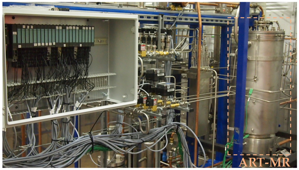
Figure 12.
Picture of the prototype reactor for the ATR process where the placement of the Autothermal Reforming-Membrane reactor (ATR-MR) is highlighted.
2.4.2. WGS Prototype
The pilot prototype is designed for producing 5 Nm3/h (grade 3.0) of pure hydrogen in a water gas shift membrane reactor. The reactor separates hydrogen in-situ right where it is produced by means of WGS reaction. The complete setup includes the steam methane reformer which feeds the membrane reactor with real syngas rather than simulated gas from cylinders. Such a setup allowed the evaluation of the integration and definition of controls under realistic conditions (Figure 13). The WGS prototype consisted of a fixed bed membrane reactor with 33 Pd-based membranes of 22–23 cm long (OD 10 mm–ID 7 mm) prepared by electroless plating.
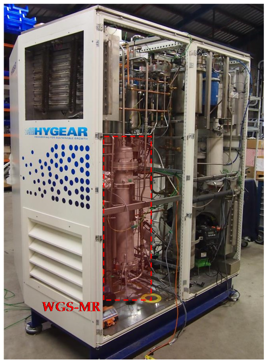
Figure 13.
Picture of the prototype reactor for WGS process where the placement of the WGS-MR is highlighted.
2.4.3. FTS Prototype
The pilot scale prototype for Fischer Tropsch in a membrane reactor was built and assembled into a test setup. In this reactor 5 Pd-based hydrogen permeating membranes were coupled in the reactor for controlled distribution of hydrogen in order to get the required H2/CO ratio along the reactor. A picture of the reactor used for the prototype experiments is depicted in Figure 14.
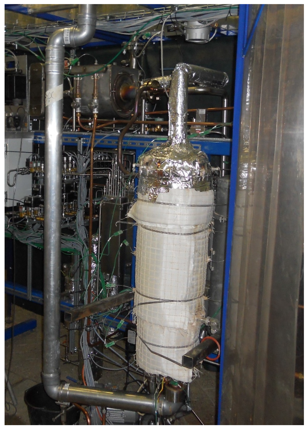
Figure 14.
Picture of the prototype reactor for the Fischer-Tropsch (FTS) process.
2.4.4. OCM Prototype
The oxidative coupling of the methane membrane reactor (OCM-MR) employs MIEC membranes, which avoids the use of expensive cryogenic separation units for production of oxygen. The match between the temperatures for OCM reaction and permeation of oxygen between 800 and 900 °C is crucial for this concept. The system holds up to 20 MIEC membranes for oxygen separation. When debugging the prototype reactor, gas leakages from each bundle equipped with membranes was observed. Due to failure of the overall installed membranes, it was not possible to test and validate the OCM-MR prototype. A picture of the reactor constructed for the pilot scale demonstration is shown in Figure 15.
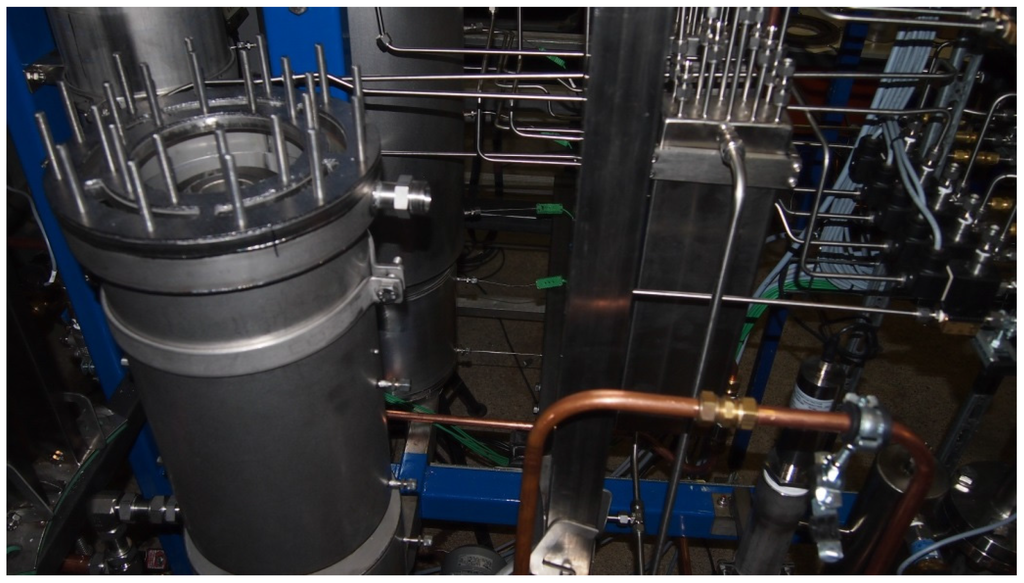
Figure 15.
Picture of the prototype reactor for the Oxidative Coupling of Methane (OCM) process.
3. Results and Discussion
In this section the main outcome obtained from the DEMCAMER project is presented. All processes investigated in the DEMCAMER project involved the development and study of different catalysts for the process, membranes, lab-scale facilities, etc. Due to this fact, this section is divided into sub-sections containing the main results obtained in each process.
3.1. Autothermal Reforming of Methane
The whole process was designed starting from the development of the catalyst for the process, which should show good activity under the operating conditions in membrane reactors. In parallel, MIEC membranes were prepared and the stability and performance assessed. Subsequently, the catalyst and membranes were combined for the demonstration of the concept at lab scale and, finally to pilot plant scale.
The developed final generation ATR catalyst achieved the required targets proposed in the project related to activity, selectivity, and stability. The final composition of this catalyst is NiPd/10Ce0.5Zr0.5O2/Al2O3, which shows a good performance as summarized in Table 2, where the target objective and the developed catalyst for ATR are compared. The interaction of Ni and Pd makes a structure suitable for the ATR process [15]. The effect of the support and loading were compared in terms of both catalytic activity under reacting conditions and characterization, giving as results the developed catalyst abovementioned prepared by sequential impregnation of Ni and Pd, which gives better results as compared to co-impregnation methods.
Table 2.
Compliance of ATR catalyst developed in DEMCAMER with the requirements of activity, selectivity and durability [14,15].
The ATR catalyst shows also stable performance (methane conversion >90%, hydrogen yield >80%) and resistance to deactivation by sulfur and carbon deposition during 100 h of operation under reaction feed containing 50 ppm of H2S (Figure 16). Characterization of used catalysts showed excellent resistance to deactivation by carbon formation (no carbonaceous deposits on used catalyst).
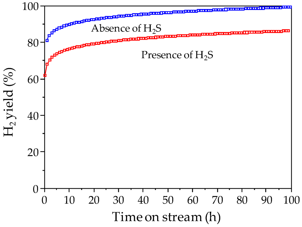
Figure 16.
Long term catalyst testing in ATR of CH4 (T = 850 °C, CH4:H2O:O2 = 1:2.5:0.75) of ATR catalyst developed in DEMCAMER project.
Once the catalysts was designed and tested under reacting conditions, the stability of MIEC membranes was also investigated for selective feeding of O2 in the reactor. The BCFZ membrane showed high fluxes and good stability for more than 1000 h as reported in Figure 17, where it can be observed that after a first activation period of around 50 h (due to adjustments in the lattice structure of the MIEC) the membrane flux remained very stable even after repeated cooling down and heating up of the system.
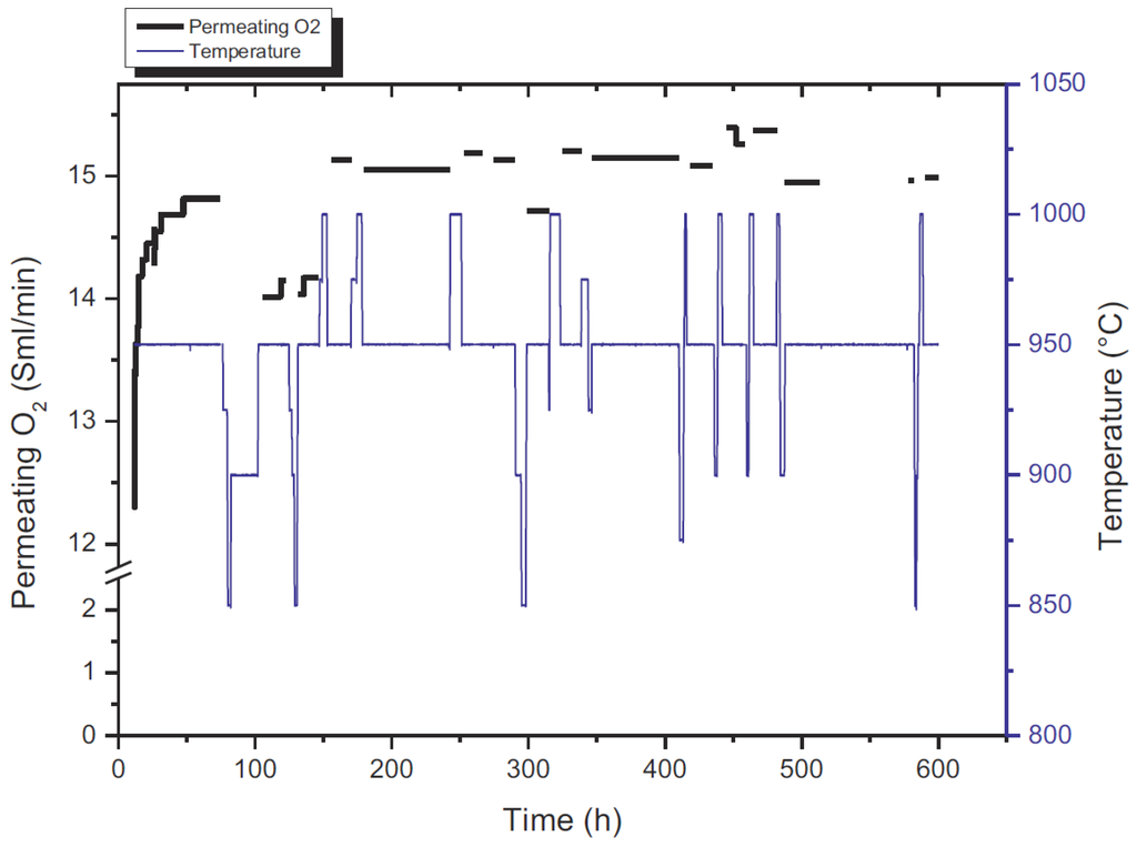
Figure 17.
Permeating O2 flow rate in the outlet of the perovskite membrane reactor with 0.5 mm thickness, permeate side [35]. He flow: 100 mL/min, air flow = 500 mL/min.
The observed Arrhenius plot for different He flowrates in the permeate side as a function of temperature (Figure 18) shows a constant slope, which implies that the activation energy is not a function of the sweep gas flow rate, and thus represents the activation energy of the perovskite itself.
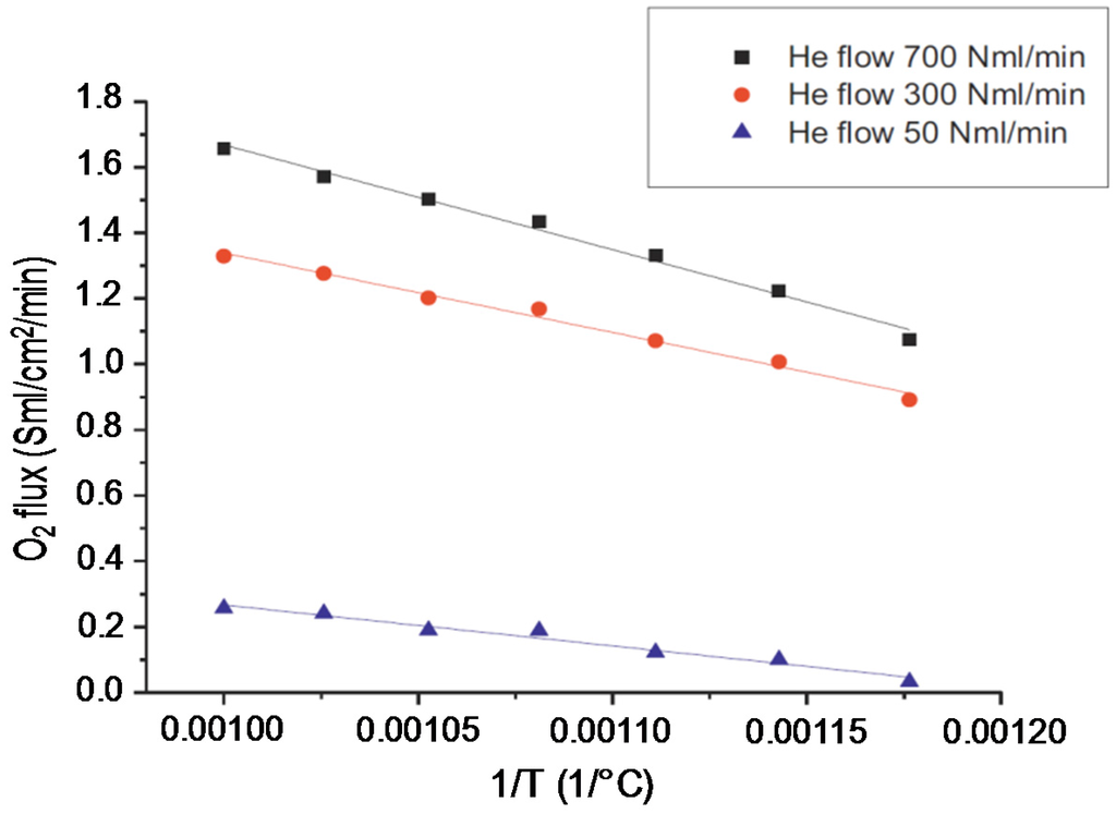
Figure 18.
Arrhenius plot for the MIEC membrane (0.5 mm thickness) as a function of He flow rate in the permeate side with an air flow rate of 2000 mLN/min in the retentate [35].
This effect was also observed by other researches using the same type of MIEC membranes [41]. The same membrane was prepared using different thicknesses and non-linearity was observed in terms of O2 permeation with increasing membrane thickness. This suggests that bulk diffusion of O2 through the membrane and surface exchange kinetics have a strong effect on the limitation in O2 permeation.
Once the catalyst and membrane were developed and investigated, when both were combined in the lab-scale reactor described in Section 2.3.1, the membranes were not able to withstand the high temperature process and they showed leakages from the sealing points. Therefore it was not possible to test the ATR process at lab scale.
The last step for the ATR process was the demonstration at prototype scale. The facility constructed at HyGear showed leakage from each bundle equipped with membranes. Due to this fact, it was not possible to feed the oxygen required for the autothermal operating condition. Under this situation the prototype reactor was operated and tested as a natural gas steam reformer. During the testing (ca. one week) the system was stable and allowed the production of up to 3.3 Nm3 of H2 per Nm3 of natural gas feed. The novel developed catalyst exhibited good activity and stability: test results showed almost complete conversion (>99%) and hydrogen productivity higher than 90%.
3.2. Water Gas Shift
The procedure followed for the development of the WGS process using the DEMCAMER technology was similar to the line-time presented for ATR. The WGS catalyst developed showed very high WGS activity and stability, demonstrating an important improvement with respect to the state-of-the art FeCr HT WGS commercial catalyst (Figure 19).
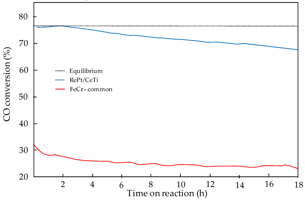
Figure 19.
Comparison of CO conversion over the WGS catalyst developed in DEMCAMER and state-of-the-art Fe/Cr catalyst (400 °C, SV = 23,230 L·h−1·kg−1) [18].
Characterization of the catalyst demonstrated that the addition of Re to the Pt-based catalysts implies a modification in the intrinsic WGS activity and also provides high stability over time. The addition of Re is also considered to be responsible for preventing Pt sintering, which would imply a strong decrease in the stability over time observed during the catalytic screening tests. All these characteristics improve the behavior of the catalyst under WGS reacting conditions and, therefore, it was selected as the catalyst for the process.
The stability and sealing of the ceramic supported Pd-based membranes developed for this process were first investigated. The new sealing method consisted in using graphite gaskets and Swagelok connectors. In this way, the difference in thermal expansion of the ceramic tube and the Swagelok piece is absorbed by the gasket with an intermediate thermal expansion. Thermal cycles for the membrane proved the stability of the sealing method as depicted in Figure 20. Furthermore, single gas permeation tests showed that the Pd-based membrane gave one of the highest permeances ever reported in the literature. A table with the comparison of different Pd-based membranes investigated in the literature can be found in Fernandez et al. [38].
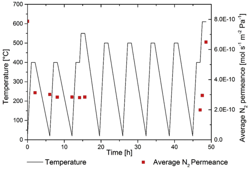
Figure 20.
N2 leakages as a function of thermal cycles for the ceramic supported Pd-based membrane with a pressure difference of 3 bar. Cooling and heating in N2 atmosphere [39].
First, lab-scale tests were carried out both in PBMR and FBMR, using the catalyst and membranes (thickness 3.6 μm) developed in the project. Even though the catalyst exhibited superior performance in a traditional reactor configuration, in both cases, the combination resulted in a significant drop (98%) in membrane permeance, probably owing to interactions between membrane and catalysts as depicted in Figure 21.
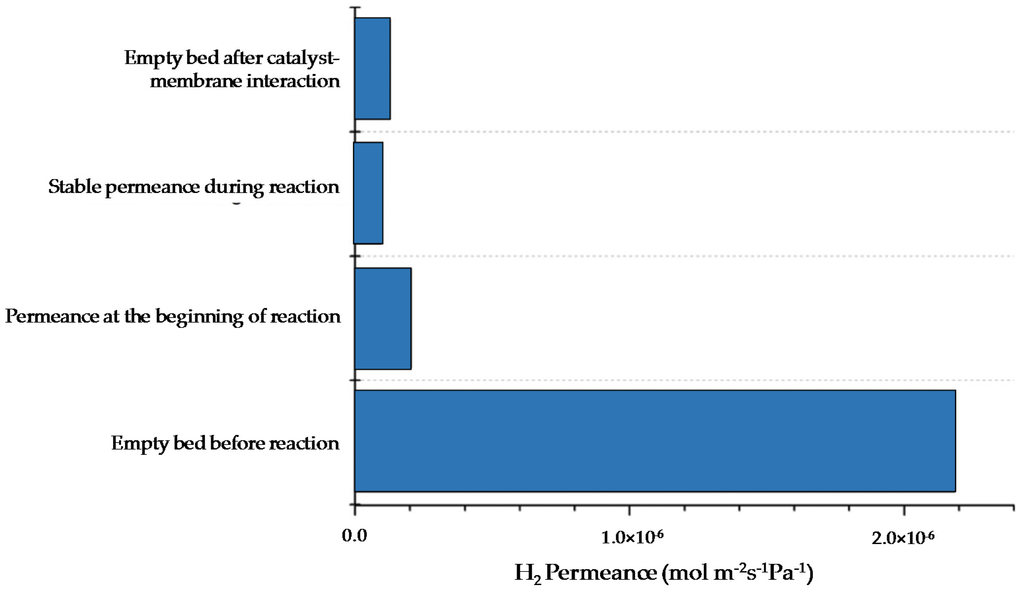
Figure 21.
Comparison of H2 permeance at different moments in time before and after interaction of the catalyst with the Pd surface (400 °C) [38].
To overcome this drawback, a commercial catalyst was used with another membrane developed in DEMCAMER with the same characteristics of that previously mentioned and no significant drop in performance was observed. In addition, the combination between a Pd-Ag commercial membrane (100 μm thickness) from REB Research & Consulting and Goodfellow and the DEMCAMER catalyst did not show any drop in the membrane permeance. The overall performance of the membrane reactor resulted in being among the best in the literature in terms of both CO conversion and hydrogen recovery (96% CO conversion and 84% H2 recovery at 400 °C, 4 bar and a gas hourly space velocity of 2500 h−1), when the Pd-Ag membrane developed in DEMCAMER and commercial catalyst were used.
In addition, very extensive validation tests of fluidized bed membrane reactors were achieved. Both commercial and the developed Pd-based membranes were tested in single tube and multi-tube configurations and with different catalysts. In fluidization conditions, the performance of the WGS-MR process was assessed for more than 800 h where the system was able to achieve flux and selectivities well above the initial targets. Best results show CO levels in the permeate side at levels of 5–7 ppm, which means that the produced hydrogen (recovered up to 60% in these tests) could be directly used in fuel cells. Additionally the catalyst did not react with nor stick to the membrane surface. These results fully demonstrate the WGS reactor concept at lab-scale conditions.
The testing and validation of the WGS-MR prototype was performed afterwards. The upgrading, by the WGS reaction, of a syngas mixture in a packed bed membrane reactor integrated downstream of a reformer was proven on a pilot scale. The results at prototype level showed 20% of hydrogen recovery using only 63% of the design membrane area. In this system the hydrogen purity grade achieved was 2.5. The system, tested for ca. 1000 h at several operating conditions showed stable performance. During the testing time, an increasing trend of membrane performance was overall observed. From the initial value, less than 10%, a maximum H2 recovery of 20% was observed. Overall, the increase in WGS feed temperature promoted the H2 permeation.
3.3. Fischer Tropsch
While for the WGS process, ceramic supported Pd-Ag membranes were used for selective H2 separation from the reaction system, similar Pd-Ag membranes were used in the FTS reaction for controlled feeding of H2 into the catalytic bed in order to enhance the selectivity to the products.
The catalyst developed for the DEMCAMER project (B-Ru/TiO2) achieved high values of activity, selectivity, and stability in compliance with the initial targets (Table 3) proposed. It should be mentioned that hydrocarbon productivity with the final FTS catalyst formulation was higher than that reported for the benchmark Co-based and also identified in the industrial requirements for the intensification of targeted FTS reaction. The stability of the B-Ru/TiO2 FTS catalyst achieves a CO conversion above 60% maintained for up to 80 h on stream, hence the stability under reacting conditions was also demonstrated.
Table 3.
Compliance of FTS catalyst developed in DEMCAMER with the requirements of activity and selectivity.
This catalyst was used for the demonstration of the reactor concept at lab-scale. Before this, the performance of the Pd-Ag membrane used in this process has been evaluated. In this case the membrane was prepared by standard electroless platting. However, the normal operating conditions for these types of membranes is always above 300 °C in order to avoid “embrittlement” of the Pd-layer resulting in a decrease in the ideal selectivity. However, FTS process takes place at lower temperatures and this effect might be present in the system. Due to this fact, more Ag is added in the metallic layer, which increases the resistance to this defect at lower temperatures. In this case the Ag was added into the membrane by PVD techniques.
Another problem associated with the FTS reaction, and related to the use of selective Pd-Ag membranes for H2 separation (feeding for this process), is the presence of CO in the bed. CO is a poisoning gas for the membranes since it becomes adsorbed in the matrix of the Pd layer, therefore reducing the surface area available for permeation. Moreover, the CO poisoning effect is even more important at lower temperatures, which is actually the case of interest. Figure 22 shows the effect of the gas fed into the system on the amount of H2 permeated through the membrane. As observed, for the same H2 partial pressures at both sides of the membrane, the presence of CO clearly effects H2 permeation in the system. Once having studied the effect of CO on the membrane, lab-scale experiments were carried out in the setup described in Section 2.3.3. In this case, two different configurations were compared (packed bed reactor with and without membrane).
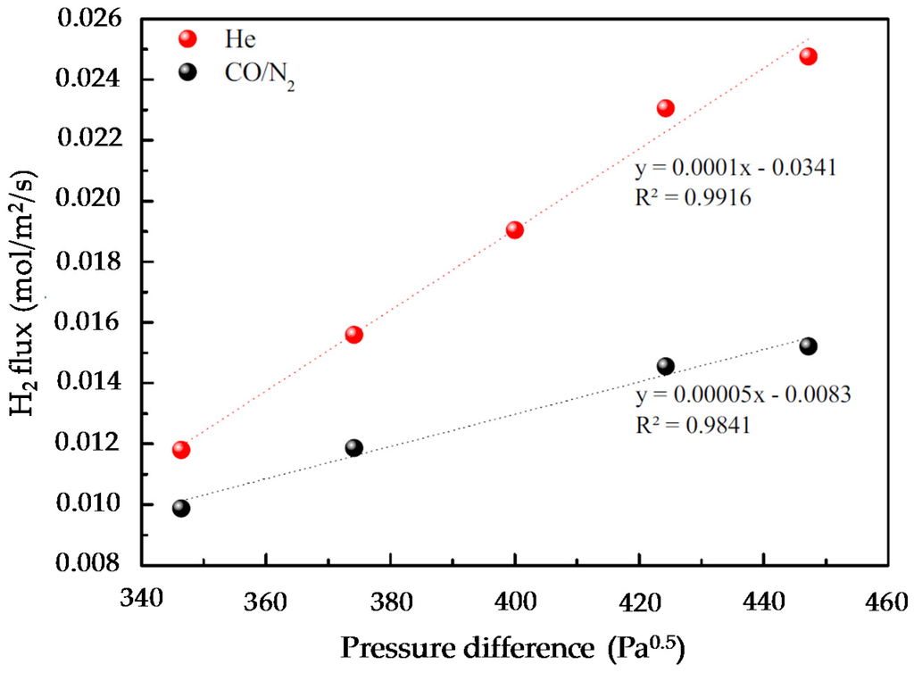
Figure 22.
H2 flux at 280 °C as a function of pressure difference when feeding He (red) or a gas mixture CO/N2 from inside the membrane [24].
The best conditions in terms of selectivity for the desired products were obtained when poor H2 syngas (H2/CO = 1) was fed into the reaction chamber from the inside of the membrane, while the H2 needed to reach the right FTS stoichiometry (H2/CO = 2) was fed (and properly distributed) into the reaction chamber through the Pd-based membranes by flowing H2/He at the outer side of the membrane. Figure 23 compares CO conversion for the different concepts investigated. It is observed that the PB-MR configuration gets an intermediate CO conversion (37.9%) compared to the packed bed system with the stoichiometric H2/CO ratio of two (50.7%) and much higher than the H2/CO ratio of one (14.1%). Positively, product selectivity is remarkably affected by the “more adequate” H2-distribution attained in the PB-MR and the selectivity towards the targeted high-molecular hydrocarbons increases by a factor of four. In addition, a significant decrease of CH4 production (from 60% to 15%) is also observed when compared to PB. Under the studied experimental conditions, membranes tend to deactivate after a few hours on stream (probably due to the formation of waxes) but their performance can be recovered by in-situ thermal treatments under inert atmosphere as explained in the literature [24].
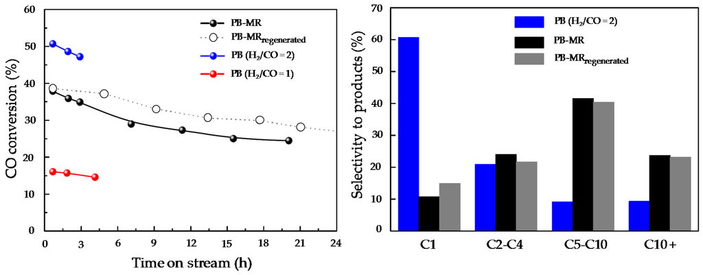
Figure 23.
(left) CO conversion at 280 °C vs. time-on-stream for the following configurations: PB-MR (H2/CO = 1) inside (black line), PBR H2/CO = 2 (blue line) and PBR H2/CO = 1 (red line) at P = 10 bar, GHSV = 7500 mLCO+H2/gcat/h; ΔPH2 = 9 bar; (right) Product selectivity [24].
3.4. Oxidative Coupling of Methane
The same MIEC membranes prepared and tested for the ATR process were used during the OCM process. Therefore this section is focused on the catalyst activity, lab scale reaction, and final prototype reaction, but not on the membranes themselves as they have already been presented and discussed in Section 3.2.
The developed OCM catalyst for the project achieved a high activity/selectivity (CH4 conversion = 55%, C2 yield = 22%), which is close to the best results reported in the state-of-the-art literature.
Lab scale reaction was carried out by placing the developed catalyst inside the MIEC membrane and selective feeding of oxygen from the retentate side. Lab scale experiments were performed at different temperatures and the phase maps of five identified crystalline phases and one amorphous phase of the catalyst (also the BCFZ reflection) were monitored in the X-Ray diffraction computed tomography (XRD-CT) equipment (Figure 24). At room temperature, Mn2O3 and Na2WO4 are clearly present as active phases in the catalyst (also the support SiO2 (cristobalite and tridymite) can be clearly identified). However, once the reaction takes place at 675 °C, it is observed that the Na2WO4 phase disappears, which corresponds to the formation of an amorphous phase. Simultaneously, the formation of a new crystalline phase near the membrane and identified as BaWO4 is observed, which implies a migration of the active phases in the catalysts to a new reorganization that occurs at high temperatures. This effect can be better observed after OCM reaction via Scanning Electron Microscopy coupled with Wavelength Dispersive X-ray Spectrometry (SEM–WDS) characterization in the surroundings of the BCFZ membrane. In Figure 25, where qualitative elemental analysis is depicted at two different magnifications, the migration of W from the catalyst to the surface of the membrane to form the BaWO4 is observed, which supports the findings observed in the XRD-CT reaction monitoring.
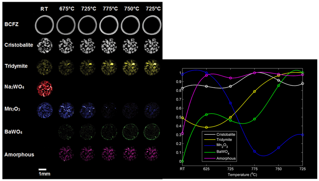
Figure 24.
Phase maps obtained from the X-Ray diffraction computed tomography (XRD-CT) data (integrated intensities) of the BaCoxFeyZrzO3-δ BCFZ membrane phase and the catalyst phases: cristobalite and tridymite (SiO2 polymorphs), Na2WO4, Mn2O3, Ba2WO4, and an amorphous phase [28].
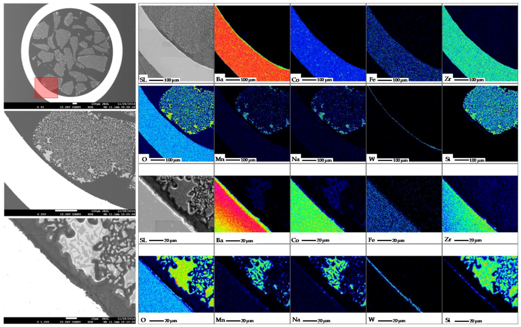
Figure 25.
Scanning Electron Microscopy coupled with Wavelength Dispersive X-ray Spectrometry (SEM-WDS) analysis of a cross sectional area of the OCM lab scale reactor used. The red rectangle represents the area covered for the analysis [28].
The outflow gases from the OCM lab-scale reactor were analyzed with mass spectrometry. In this case, different scenarios are presented in Figure 26 corresponding to different gas mixtures of CH4 diluted in He). It can be observed that the presence of C2+ (pink trend in Figure 26) is only observed once the reaction starts (i.e., when diluted CH4 is fed into the reactor) and it is increased with increasing fuel concentration at the inlet of the reactor. What becomes more interesting is that, even though there is migration of W towards the membrane, higher hydrocarbons molecules as compared to CH4 are formed during the reaction (C2 and C3 fractions).
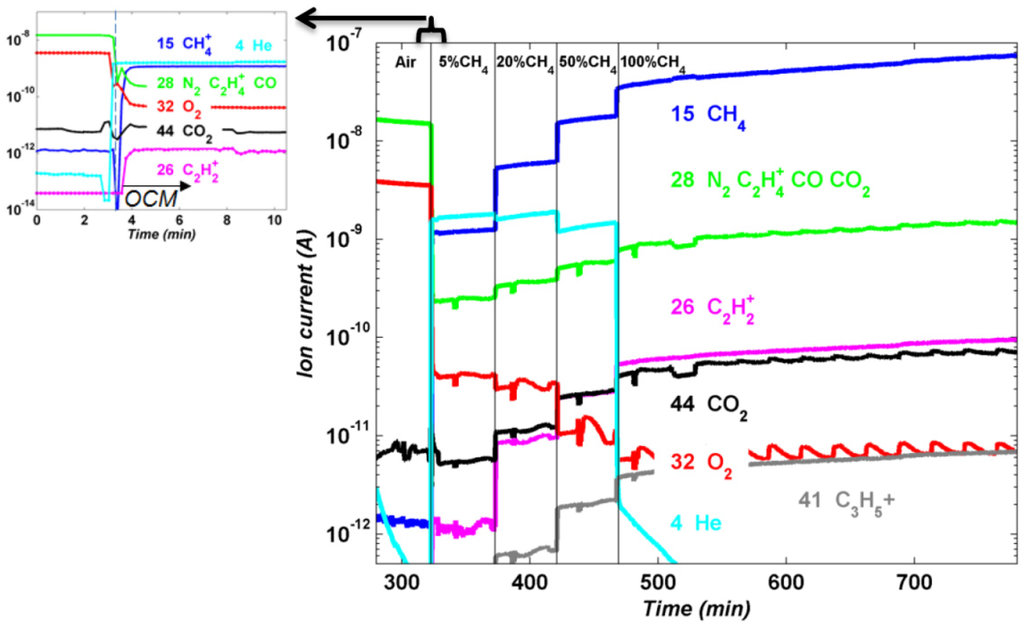
Figure 26.
Mass spectroscopy data that correspond to the following masses: 4 (He—cyan), 15 (CH4—blue), 28 (N2, CO, C2H4+—green), 32 (O2—red), 44 (CO2—black) and 26 (C2+—pink) [28].
Moving towards the prototype reactor, the MIEC membranes were not able to withstand the mechanical strength required for the coupling to the reactor and at this stage the technology for the OCM reaction failed to deliver results beyond the laboratory scale. In order to demonstrate the OCM-MR concept, significant improvements are needed on the robustness of the MIEC membranes before any industrial application under safe conditions could be imagined.
4. Conclusions
The DEMCAMER project aimed at the development of novel membrane reactors to provide important process intensification for key processes in the chemical engineering field. The industrial processes studied in this project have some drawbacks (viz. global efficiency, CO2 emissions, and volume of the process) that can be solved or reduced by using more compact systems that integrate reaction and separation in the same unit. For all the processes studied in this project (ATR, WGS, FTS and OCM), the streamline followed was similar. First was the development of active catalysts for the experimental conditions present in membrane reactors, which differ from those in benchmark technologies. In parallel, improved membranes for H2 and O2 permeation were investigated. In general, stability over time and mechanical resistance were the two main characteristics aimed for in this project. Subsequently, the interaction between the catalyst and the membranes, and the performance of the reactor concept were proven at lab-scale when combining both at reactive conditions. Finally, and following Hazard and Operability (HAZOP) procedures, all membrane reactors were scaled up to prototype scale.
The different catalysts developed for the processes showed catalytic activities well above the DEMCAMER targets. The Ni-Pd catalyst developed for the ATR reaction has improved activities and selectivity as compared to state-of-the-art catalysts due to the synergistic interaction Ni-Pd and the optimized oxygen storage capacity on the cerium support. The catalyst for WGS (Pt-Re over Ce-Ti mixed oxide) has shown high stability over time with high CO conversions. However, interaction of the Ti with the membrane was observed, resulting in the underperformance of the membranes used for the WGS reaction. For the FTS process, a B-Ru/TiO2 catalyst was developed, which showed good stability and resistance to sulfur poisoning and carbon formation. The Mn-Na-W/SiO2 catalyst for OCM also showed high CH4 conversions with good selectivity to C2+ with results close to state of the art catalysts. The catalyst shows an optimal active phase exposition through XRD-CT analysis, whereas the surface phase is modified in the presence of membranes as a consequence of W migration from the catalyst to the membrane surface. However, W migration did not affect the conversion of CH4 to higher hydrocarbons.
Two different types of membranes were improved within the project: MIEC membranes for selective oxygen separation from air and ceramic supported Pd-based membranes for selective H2 separation. Stability of both membranes was confirmed through single gas permeation tests at operating temperatures over many hours without any decrease in the membrane performance. Furthermore, new sealing methods were tested and proposed in order to fix the membranes inside the membrane reactors. Permeances and selectivities obtained with the different membranes prepared in the project are among the best ever reported in the literature and well above the targets for the DEMCAMER project. For the different processes investigated, the preferred configuration is the packed bed membrane reactor due to higher simplicity in the configuration. In addition, stability was also assessed in the fluidized bed membrane reactor configuration for the WGS reaction.
All the different processes were investigated at lab-scale and only the OCM process failed due to the lack in mechanical strength of the membranes when connected to the reactor. Possible interactions between catalysts and membranes were observed for the WGS and OCM processes. This effect was remarkable for Pd-based membranes, where the permeance of H2 dropped significantly and membrane reactor performance was affected. However, during the OCM reaction using MIEC membranes the interaction between tungsten (W) and the surface of the membrane did not alter the selectivities to products. At the final stage, all processes were considered for prototype validation. However the prepared MIEC membranes were not able to handle the assemblage to the reactor and the demonstration failed for OCM. The ATR reactor was tested with an external heat source because damages in the MIEC membranes did not allow the oxygen permeation at prototype scale to be tested. In the case of FTS prototype demonstration, the reaction system did not progress to the desired products. The WGS prototype system was fully demonstrated using syngas from a reformer reactor installed upstream of the WGS reactor. In this case, a pure H2 stream (grade 2.5) was obtained and reaction was maintained for more than 40 days without any drop in the performance. At this stage, only the WGS concept achieved TLR level 5, whereas the other processes investigated in this project remained in TLR level 4.
According to the results obtained in the DEMCAMER project, only WGS can be considered beyond prototype scale for industrial application. However, many efforts should still be carried out to improve the standard sealing methods and poisoning of the active layer by CO and sulfur.
Acknowledgments
The research leading to these results received funding from the European Union Seventh Framework Programme (FP7/2007-2013) under grant agreement n° NMP3-LA-2011-262840 (DEMCAMER project).

Author Contributions
All authors contributed to writing and correcting the paper. Jose Luis Viviente was the project coordinator of DEMCAMER, Fausto Gallucci was the Technical Manager, Leonardo Roses was the Exploitation Manager and Adele Brunetti the Dissemination Manager of DEMCAMER.
Conflicts of Interest
The authors declare no conflict of interest.
References
- Reay, D.; Ramshaw, C.; Harvey, A. Process Intensification; Elsevier: Oxford, UK, 2008. [Google Scholar] [CrossRef]
- IPCC. IPCC Special Report on Carbon Dioxide Capture and Storage; Cambridge University Press: Cambridge, UK, 2005. [Google Scholar]
- Gallucci, F.; Fernandez, E.; Corengia, P.; van Sint Annaland, M. Recent advances on membranes and membrane reactors for hydrogen production. Chem. Eng. Sci. 2013, 92, 40–66. [Google Scholar] [CrossRef]
- Gallucci, F.; Comite, A.; Capannelli, G.; Basile, A. Steam Reforming of Methane in a Membrane Reactor: An Industrial Case Study. Ind. Eng. Chem. Res. 2006, 45, 2994–3000. [Google Scholar] [CrossRef]
- Matsumura, Y.; Tong, J. Methane Steam Reforming in Hydrogen-permeable Membrane Reactor for Pure Hydrogen Production. Top. Catal. 2008, 51, 123–132. [Google Scholar] [CrossRef]
- Yakabe, H.; Kurokawa, H.; Shirasaki, Y.; Yasuda, I. Operation of palldium membrane reformer system for hydrogen production: The case of Tokio Gas. In Palladium Membrane Technology Hydrogen Production Carbon Capture Other Applications; Woodhead Publishing: Amsterdam, The Netherlands, 2015; p. 311. [Google Scholar]
- Deshmukh, S.A.R.K.; Heinrich, S.; Mörl, L.; van Sint Annaland, M.; Kuipers, J.A.M. Membrane assisted fluidized bed reactors: Potentials and hurdles. Chem. Eng. Sci. 2007, 62, 416–436. [Google Scholar] [CrossRef]
- Brunetti, A.; Drioli, E.; Barbieri, G. Energy and mass intensities in hydrogen upgrading by a membrane reactor. Fuel Process. Technol. 2014, 118, 278–286. [Google Scholar] [CrossRef]
- Barbieri, G.; Brunetti, A.; Caravella, A.; Drioli, E. Pd-based membrane reactors for one-stage process of water gas shift. RSC Adv. 2011, 1, 651–661. [Google Scholar] [CrossRef]
- Droescher, M. SusChem, Innovating for a Better Future. In Proceedings of the European Conference on Biorefinery Research, Helsinki, Finland, 19–20 October 2016; p. 104.
- Lo Faro, M.; Frontera, P.; Antonucci, P.; Arico, A.S. Ni-Cu based catalysts prepared by two different methods and their catalytic activity toward the ATR of methane. Chem. Eng. Res. Des. 2015, 93, 269–277. [Google Scholar] [CrossRef]
- Sepehri, S.; Rezaei, M.; Garbarino, G.; Busca, G. Facile synthesis of a mesoporous alumina and its application as a support of Ni-based autothermal reforming catalysts. Int. J. Hydrog. Energy 2016, 41, 3456–3464. [Google Scholar] [CrossRef]
- Marra, L.; Wolbers, P.F.; Gallucci, F.; Annaland, M.V.S. Development of a RhZrO2 catalyst for low temperature autothermal reforming of methane in membrane reactors. Catal. Today 2014, 236, 23–33. [Google Scholar] [CrossRef]
- Ismagilov, I.Z.; Matus, E.V.; Kuznetsov, V.V.; Mota, N.; Navarro, R.M.; Yashnik, S.A.; Prosvirin, I.P.; Kerzhentsev, M.A.; Ismagilov, Z.R.; Fierro, J.L.G. Hydrogen production by autothermal reforming of methane: Effect of promoters (Pt, Pd, Re, Mo, Sn) on the performance of Ni/La2O3 catalysts. Appl. Catal. A Gen. 2014, 481, 104–115. [Google Scholar] [CrossRef]
- Ismagilov, I.Z.; Matus, E.V.; Kuznetsov, V.V.; Kerzhentsev, M.A.; Yashnik, S.A.; Prosvirin, I.P.; Mota, N.; Navarro, R.M.; Fierro, J.L.G.; Ismagilov, Z.R. Hydrogen production by autothermal reforming of methane over NiPd catalysts: Effect of support composition and preparation mode. Int. J. Hydrog. Energy 2014, 39, 20992–21006. [Google Scholar] [CrossRef]
- Gil, A.G.; Wu, Z.; Chadwick, D.; Li, K. Ni/SBA-15 Catalysts for combined steam methane reforming and water gas shift—Prepared for use in catalytic membrane reactors. Appl. Catal. A Gen. 2015, 506, 188–196. [Google Scholar] [CrossRef]
- Jain, R.; Poyraz, A.S.; Gamliel, D.P.; Valla, J.; Suib, S.L.; Maric, R. Comparative study for low temperature water-gas shift reaction on Pt/ceria catalysts: Role of different ceria supports. Appl. Catal. A Gen. 2015, 507, 1–13. [Google Scholar] [CrossRef]
- Villar, V.; Barrio, L.; Helmi, A.; Annaland, M.V.S.; Galucci, F.; Fierro, J.L.G. Effect of Re addition on the WGS activity and stability of Pt/CeO2-TiO2 catalyst for membrane reactor applications. Catal. Today 2016, 268, 95–102. [Google Scholar] [CrossRef]
- Bayat, M.; Rahimpour, M.R. A novel cascade fluidized-bed reactor assisted by hydrogen permselective membrane concept for improving gasoline productivity and selectivity in Fischer-Tropsch synthesis: A simulation study. J. Nat. Gas Sci. Eng. 2013, 13, 20–29. [Google Scholar] [CrossRef]
- Rahimpour, M.R.; Mirvakili, A.; Paymooni, K.; Moghtaderi, B. A comparative study between a fluidized-bed and a fixed-bed water perm-selective membrane reactor with in situ H 2O removal for Fischer-Tropsch synthesis of GTL technology. J. Nat. Gas Sci. Eng. 2011, 3, 484–495. [Google Scholar] [CrossRef]
- Iglesia, E. Design, synthesis, and use of cobalt-based Fischer-Tropsch synthesis catalysts. Appl. Catal. A Gen. 1997, 161, 59–78. [Google Scholar] [CrossRef]
- Carballo, J.M.G.; Yang, J.; Holmen, A.; García-Rodríguez, S.; Rojas, S.; Ojeda, M.; Fierro, J.L.G. Catalytic effects of ruthenium particle size on the Fischer-Tropsch Synthesis. J. Catal. 2011, 284, 102–108. [Google Scholar] [CrossRef]
- Hosseini, S.A.; Taeb, A.; Feyzi, F. Evaluation of Ru-promoted Co/γ-Al2O3 catalysts in Fischer-Tropsch synthesis in a CSTR. Catal. Commun. 2005, 6, 233–240. [Google Scholar] [CrossRef]
- Liuzzi, D.; Pérez-Alonso, F.J.; Fierro, J.L.G.; Rojas, S.; van Wijk, F.L.; Roghair, I.; van Sint Annaland, M.; Fernandez, E.; Viviente, J.L.; Tanaka, D.A.P. Catalytic membrane reactor for the production of biofuels. Catal. Today 2016, 268, 37–45. [Google Scholar] [CrossRef]
- Choudhary, V.R.; Uphade, B.S.; Mulla, S.A.R. Oxidative Coupling of Methane over a Sr-Promoted La2O3 Catalyst Supported on a Low Surface Area Porous Catalyst Carrier. Ind. Eng. Chem. Res. 1997, 36, 3594–3601. [Google Scholar] [CrossRef]
- Yu, L.; Li, W.; Ducarme, V.; Mirodatos, C.; Martin, G.A. Inhibition of gas-phase oxidation of ethylene in the oxidative conversion of methane and ethane over CaO, La2O3/CaO and SrO-La2O3/CaO catalysts. Appl. Catal. A Gen. 1998, 175, 173–179. [Google Scholar] [CrossRef]
- Serres, T.; Aquino, C.; Mirodatos, C.; Schuurman, Y. Influence of the composition/texture of Mn-Na-W catalysts on the oxidative coupling of methane. Appl. Catal. A Gen. 2015, 504, 509–518. [Google Scholar] [CrossRef]
- Vamvakeros, A.; Jacques, S.D.M.; Middelkoop, V.; di Michiel, M.; Egan, C.K.; Ismagilov, I.Z.; Vaughan, G.B.M.; Gallucci, F.; van Sint Annaland, M.; Shearing, P.R.; et al. Real time chemical imaging of a working catalytic membrane reactor during oxidative coupling of methane. Chem. Commun. 2015, 51, 12752–12755. [Google Scholar] [CrossRef] [PubMed]
- Kharton, V.V.; Yaremchenko, A.A.; Kovalevsky, A.V.; Viskup, A.P.; Naumovich, E.N.; Kerko, P.F. Perovskite-type oxides for high-temperature oxygen separation membranes. J. Membr. Sci. 1999, 163, 307–317. [Google Scholar] [CrossRef]
- Leo, A.; Smart, S.; Liu, S.; da Costa, J.C.D. High performance perovskite hollow fibres for oxygen separation. J. Membr. Sci. 2011, 368, 64–68. [Google Scholar] [CrossRef]
- Wang, H.; Wang, R.; Liang, D.T.; Yang, W. Experimental and modeling studies on Ba0.5Sr0.5Co0.8Fe0.2O3−δ (BSCF) tubular membranes for air separation. J. Membr. Sci. 2004, 243, 405–415. [Google Scholar] [CrossRef]
- Shao, Z.; Yang, W.; Cong, Y.; Dong, H.; Tong, J.; Xiong, G. Investigation of the permeation behavior and stability of a Ba0.5Sr0.5Co0.8Fe0.2O3−δ. J. Membr. Sci. 2000, 172, 177–188. [Google Scholar] [CrossRef]
- Mather, G.C.; Poulidi, D.; Thursfield, A.; Pascual, M.J.; Jurado, J.R.; Metcalfe, I.S. Hydrogen-permeation characteristics of a SrCeO3-based ceramic separation membrane: Thermal, ageing and surface-modification effects. Solid State Ion. 2010, 181, 230–235. [Google Scholar] [CrossRef]
- Buysse, C.; Kovalevsky, A.; Snijkers, F.; Buekenhoudt, A.; Mullens, S.; Luyten, J.; Kretzschmar, J.; Lenaerts, S. Fabrication and oxygen permeability of gastight, macrovoid-free Ba0.5Sr0.5Co0.8Fe0.2O3−δ capillaries for high temperature gas separation. J. Membr. Sci. 2010, 359, 86–92. [Google Scholar] [CrossRef]
- Di Felice, L.; Middelkoop, V.; Anzoletti, V.; Snijkers, F.; van Sint Annaland, M.; Gallucci, F. New high temperature sealing technique and permeability data for hollow fiber BSCF perovskite membranes. Chem. Eng. Process. Process Intensif. 2014. [Google Scholar] [CrossRef]
- Fernandez, E.; Medrano, J.A.; Melendez, J.; Parco, M.; van Sint Annaland, M.; Gallucci, F. Preparation and characterization of metallic supported thin Pd-Ag membranes for high temperature hydrogen separation. Chem. Eng. J. 2015. [Google Scholar] [CrossRef]
- Medrano, J.A.; Fernandez, E.; Melendez, J.; Parco, M.; Tanaka, D.A.P.; van Sint Annaland, M.; Gallucci, F. Pd-based metallic supported membranes: High-temperature stability and fluidized bed reactor testing. Int. J. Hydrog. Energy 2015. [Google Scholar] [CrossRef]
- Fernandez, E.; Helmi, A.; Coenen, K.; Melendez, J.; Viviente, J.L.; Tanaka, D.A.P.; van Sint Annaland, M.; Gallucci, F. Development of thin Pd–Ag supported membranes for fluidized bed membrane reactors including {WGS} related gases. Int. J. Hydrog. Energy 2015, 40, 3506–3519. [Google Scholar] [CrossRef]
- Fernandez, E.; Coenen, K.; Helmi, A.; Melendez, J.; Zuñiga, J.; Tanaka, D.A.P.; van Sint Annaland, M.; Gallucci, F. Preparation and characterization of thin-film Pd–Ag supported membranes for high-temperature applications. Int. J. Hydrog. Energy 2015, 40, 13463–13478. [Google Scholar] [CrossRef]
- Brunetti, A.; Caravella, A.; Fernandez, E.; Tanaka, D.A.P.; Gallucci, F.; Drioli, E.; Curcio, E.; Viviente, J.L.; Barbieri, G. Syngas upgrading in a membrane reactor with thin Pd-alloy supported membrane. Int. J. Hydrog. Energy 2015, 40, 10883–10893. [Google Scholar] [CrossRef]
- Tong, J.; Yang, W.; Zhu, B.; Cai, R. Investigation of ideal zirconium-doped perovskite-type ceramic membrane materials for oxygen separation. J. Membr. Sci. 2002, 203, 175–189. [Google Scholar] [CrossRef]
© 2016 by the authors; licensee MDPI, Basel, Switzerland. This article is an open access article distributed under the terms and conditions of the Creative Commons Attribution (CC-BY) license (http://creativecommons.org/licenses/by/4.0/).