Article

Optimization Analysis of Structural Parameters of Special Metal Sealing for 175 MPa Tube Hanger

1
CNPC Bohai Equipment Manufacturing Co., Ltd., Tianjin 300457, China
2
CNPC R & D Center for Ultra-Deep Complex Reservior Exploration and Development, Korla 841001, China
3
Engineering Research Center for Ultra-Deep Complex Reservoir Exploration and Development, Korla 841001, China
4
Xinjiang Key Laboratory of Ultra-Deep Oil and Gas, Korla 841001, China
5
PetroChina Tarim Oilfield Company, Korla 841001, China
*
Author to whom correspondence should be addressed.
Processes 2025, 13(9), 2970; https://doi.org/10.3390/pr13092970
Submission received: 24 August 2025 / Revised: 11 September 2025 / Accepted: 13 September 2025 / Published: 18 September 2025
(This article belongs to the Special Issue New Research on Oil and Gas Equipment and Technology, 2nd Edition)

Abstract

To meet the usage requirements of the wellhead mandrel-type tube hanger of 175 MPa ultra-high pressure, four specially shaped metal sealing structures are selected as the research objects in this paper. The mechanical properties of different metal sealing structures are calculated, respectively, by using finite element software and binary regression analysis software. It was found that the mechanical properties and contact pressure fluctuations of X-shaped and straight U-shaped metal seals were relatively large, and the sealing width was relatively small among the four types of special-shaped metal seals. The mechanical properties and sealing performance of ball-drum-type metal seals and elliptical U-shaped seals were relatively stable, and the contact width was relatively large. For the single U-shaped sealing structure, the optimization rates of the maximum contact pressure and the minimum equivalent stress reached 11.63% and 10.63%, respectively. For the double U-shaped structure, the optimization rates of its maximum contact pressure and minimum equivalent stress both exceed 12%. The tests showed that the metal sealing structure met the pneumatic sealing requirement of 175 MPa. These results provide theoretical guidance for the research and design of a new type of ultra-high-pressure mandrel oil and casing hanger with a long service life and high reliability.

1. Introduction

At present, the exploration and development of oil and gas tend to focus on unconventional and ultra-deep blocks. Especially in the past three years, the pace of scientific experiments and the development of wells over 10,000 m deep has accelerated. Major discoveries have been continuously made in onshore deep and ultra-deep exploration and development, and several large deep oil fields have been efficiently built. However, the formation pressure of ultra-deep wells above 9000 m can reach as high as 200 MPa, and the formation temperature is around 200 °C. The wellhead equipment that comes with them needs to withstand these harsh service environments. This paper mainly focuses on the sealing reliability of the mandrel-type tube hanger at the wellhead. In recent years, some experts have conducted a lot of related research on the sealing structure of the casing hanger. Lian Zhanghua et al. [1,2,3,4] established a mechanical model of the casing clip by calculating that the bearing teeth caused significant stress concentration, and these stresses were unevenly distributed, ultimately resulting in casing fracture. Liu Yang et al. [5,6,7,8,9,10] conducted a systematic study on the metal sealing structure under 140 MPa high pressure and extreme temperature by using a fully metal-sealed hanger device. They also carried out material selection research and strength calculation on the mandrel and four-way. Harshkumar P. et al. [11,12,13] proposed a finite element modeling method to evaluate the performance and applicability of conventional elastomer suspension sealing components. Wang Zhanwen et al. [14,15] introduced a K-shaped metal sealing structure and optimized it by using the binary regression method. The optimized sealing structure can increase the contact pressure and reduce its own stress. Wang Yimin et al. [16,17] designed several new metal sealing structures to reduce the aging and failure of rubber seals, providing theoretical guidance for the all-metal sealing of high-pressure wellhead casing hangers. Feng Chunyu et al. [18,19,20] designed different types of metal sealing structures for the sealing problem of ultra-high-pressure hangers and analyzed the interrelationships of sealing rings under different load conditions and parameters by using the response surface method. Ren Guanlong et al. [21,22] evaluated the strength and failure criteria of a U-shaped metal sealing structure. It found that this U-shaped sealing structure can be used in high-temperature, high-pressure, and deep-water environments.
The above literature has studied the limitations of conventional casing hangers and conducted in-depth research on the sealing structure of mandrel hangers. It has proposed various types of metal sealing structures and verified the rationality of metal sealing structures. This paper mainly draws on the research results of predecessors and aims to conduct in-depth research on the existing four commonly used sealing structures under various complex working conditions. There is no relevant research on the analysis and comparison of the four types of special-shaped metal seals yet. Therefore, it is necessary to conduct a systematic comparative analysis and parameter optimization of the four types of special-shaped sealing structures. Compare the best structure among them, further verify whether it meets the 175 MPa air pressure sealing requirements, and conduct indoor and outdoor tests for verification. The research results provide theoretical guidance for the actual service assessment of the tube hanger.

2. Structure and Failure Cases of Mandrel-Type Tube Hanger

The existing mandrel-type tube hanger usually forms the main sealing unit with a combination of rubber and metal. Especially in desert and deep-water environments, the rubber parts in the hanger often undergo plastic deformation and lose their elastic capacity. In addition, the sealing parts cannot be effectively protected during the transportation and installation process, as shown in Figure 1a. The operators did not take effective protective measures for the mandrel hanger device. Especially in high-temperature, unclean, and humid environments, the surface of the sealing parts is prone to damage and loses its original sealing capacity. As shown in Figure 1b, rubber seals are also the most prone to damage during the drilling and completion process.
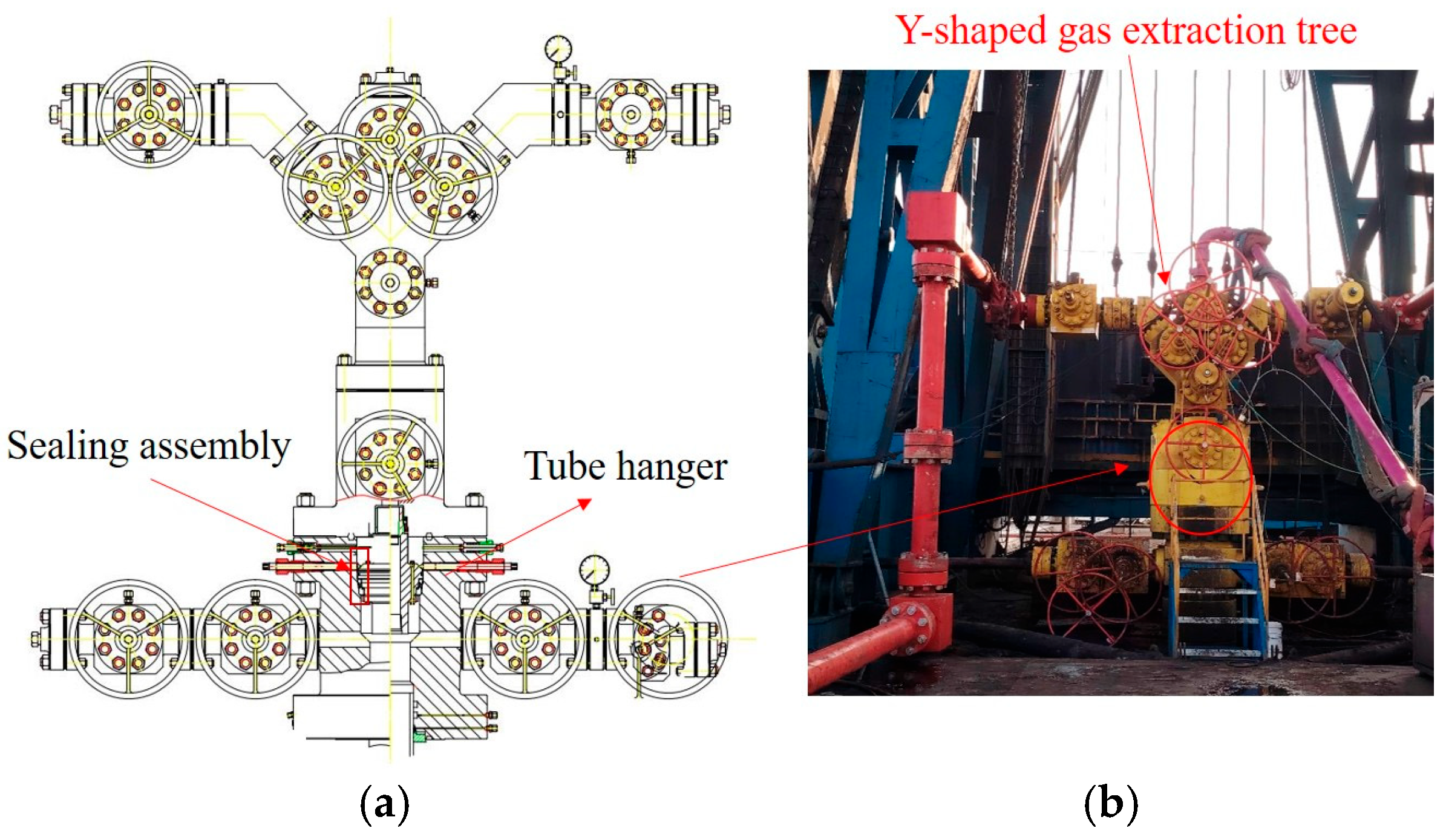
For ultra-high-pressure tube hangers in China, the conventional hybrid sealing structure with rubber and metal cannot meet the current working conditions. Therefore, the manufacturers have gradually increased their research and development efforts on the metal sealing structure of hangers, and have produced prototypes of related ultra-high-pressure products. However, the metal sealing form and working principle are still simple improvements based on the conventional structure. Figure 2 shows the assembly design drawing of the 175 MPa ultra-high-pressure tube head and the on-site installation physical photos. The lower tube hanger adopts a mandrel-type sealing structure, and the sealing assembly is a fully metal sealing structure. The lower end of the hanger is connected to a tube string with 50–400 T. On-site tests have proved that this structure can withstand a 175 MPa test oil pressure.
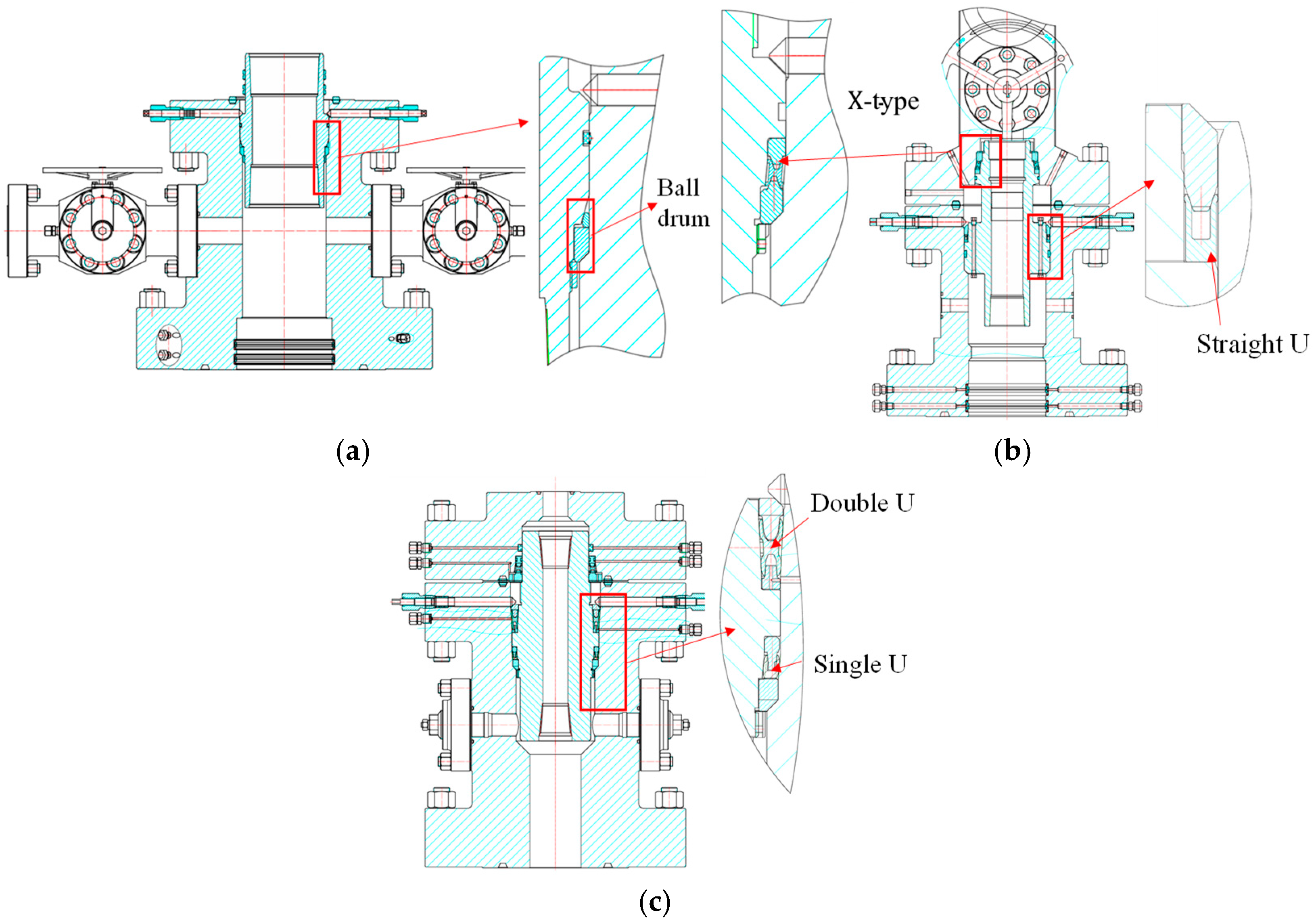
X-type, ball-drum type, straight U-shaped, and elliptical U-shaped will be analyzed and compared, and ultimately, the better combined structure is selected in this paper.

3. Research on the Performance of Special-Shaped Metal Sealing

3.1. Analysis of the Ball-Drum Seal Structure

As shown in Figure 3a, it is the mouth of an offshore well in China, which is installed in combination with a triple-hanger device. Among them, the sealing unit of the casing hanger mainly adopts X-shaped metal sealing and ball-drum metal sealing structures. Figure 3b shows the structure of the mandrel-type tube hanger, whose sealing units are mainly composed of X-shaped metal seals and straight U-shaped metal seals. Figure 3c shows the structure of the core-shaft casing hanger device. Its sealing unit is mainly composed of X-shaped metal seals and elliptical U-shaped metal seals. This structure has gradually evolved from X-shaped and H-shaped metal seal structures. Some products have been put into use in a certain oilfield, and the 140 MPa pressure test is normal [4].
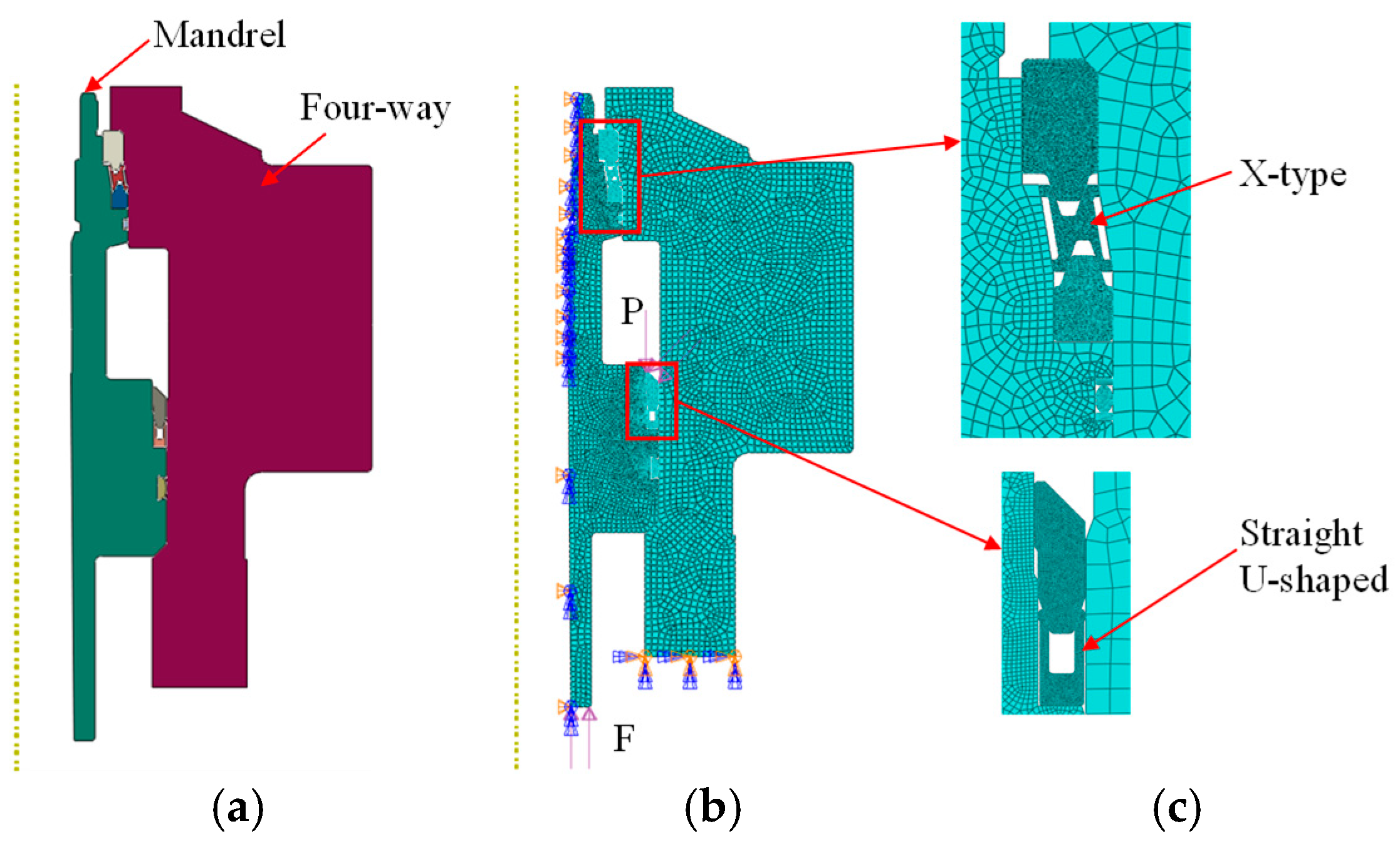
In order to verify the stress-strain laws and sealing performance of the metal sealing structure under different loads, the modeling research is conducted in accordance with the axisymmetric structure method based on the design dimensions of the mandrel-type tube hanger, as shown in Figure 3a. The unit type of the sealing structure is CAX4I by ANSYS v18.0 software in USA. The friction coefficient of the seals in contact with each other is set at 0.1. Load and boundary conditions: Throughout the analysis process, six degrees of freedom at the bottom of the four-way are constrained. By establishing different analysis steps, the finite element calculation model in Figure 4 was established. The lower end face of the four-way was fixed, and tensile loads of F = 50 t–400 t were, respectively, applied to the lower end face of the mandrel as shown in Figure 4b.
According to references [4,5,6,7,8,9,10], the mandrel material is a high-temperature nickel-based alloy, with a yield strength of approximately 750 MPa and a tensile strength of approximately 985 Mpa. The four-way material is 13Cr, with a yield strength of approximately 585 Mpa and a tensile strength of about 755 Mpa. The metal seal is selected as 316 L material, with a yield strength ranging from 275 to 310 Mpa and a tensile strength of approximately 560 Mpa. The elastic modulus of the mandrel, four-way, and metal seal is 2.06 × 10⁵ Mpa, and the Poisson’s ratio is 0.3. The S-shaped rubber ring adopts the Mooney–Rivilin model [23,24,25,26,27,28].
As shown in Figure 5, the stress range of the ball-drum seal ring fluctuates between 128.1 Mpa and 307.5 Mpa when the tensile load F is within the range of 100 tons to 400 tons. The maximum stress mainly occurs in the middle and upper parts. The upper part can undergo plastic deformation, and the stress at the contact part with the support ring is relatively small. The support ring can effectively reduce the overall stress of the metal sealing ring. The maximum stress of each key component did not exceed the yield strength under the maximum tensile load. This sealing system meets the load-bearing conditions.
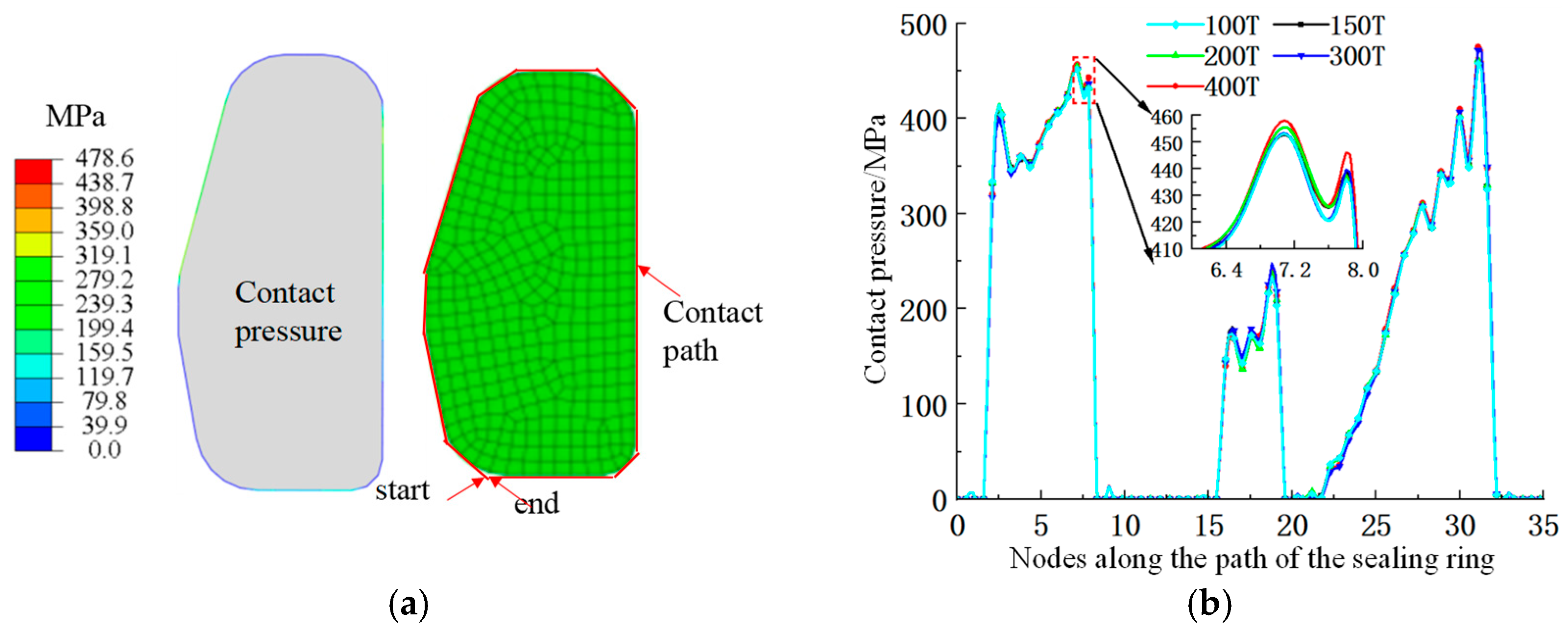
As shown in Figure 6b, the contact pressure of the ball-drum metal sealing ring varies between 300 and 500 Mpa when the suspended weight of the tube string varies between 100 t and 400 t, which can meet the sealing requirements of an ultra-high pressure of 175 Mpa. The contact pressure between the lower part of the ball-drum metal sealing ring varies between 100 and 300 Mpa. The contact pressure can meet certain sealing requirements, but the sealing specific pressure is still relatively small, which is not conducive to long-term sealing [4,8].

3.2. Analysis of Straight U-Shaped and X-Shaped Metal Seals

Figure 7a shows a combination of straight U-shaped and X-shaped metal sealing structures, which are commonly used in the sealing units of offshore wells. The material of the metal sealing unit is the same as the aforementioned material. According to the installation method and working principle of the mandrel, four-way, and two irregular metal seals, a finite element model was established. In the analysis, the load and boundary conditions were similar to those in the previous analysis. A pressure load of P = 50 MPa–175 Mpa was applied to the upper end face of the sealing pressure ring, as shown in Figure 7b.
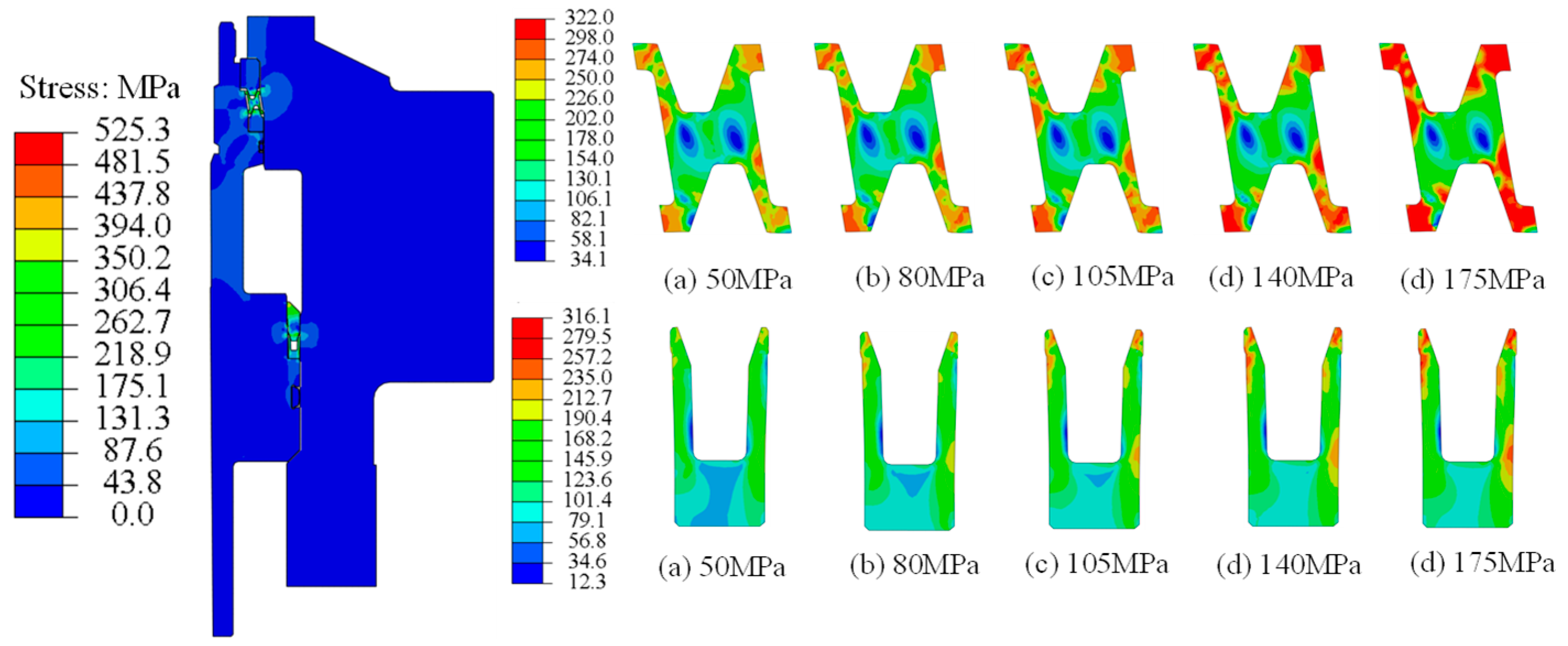
As shown in Figure 8, the stress change in the straight U-shaped sealing ring is relatively stable with the increase in load, while the stress of the X-shaped metal sealing ring rises significantly, and its deformation gradually intensifies with the increase in pressure. Especially, the maximum stress endured by the X-type metal sealing ring is between 274 MPa and 322 MPa when the upper load reaches 105 MPa to 175 MPa. Due to the compression effect, the X-type metal sealing ring undergoes significant deformation, and the overall stress level gradually increases in the height direction. Although it has enhanced the sealing effect to a certain extent, its deformation degree has approached or even exceeded the load-bearing limit of the material, posing a potential risk of structural failure. Therefore, this sealing structure can still achieve effective sealing under high load conditions.
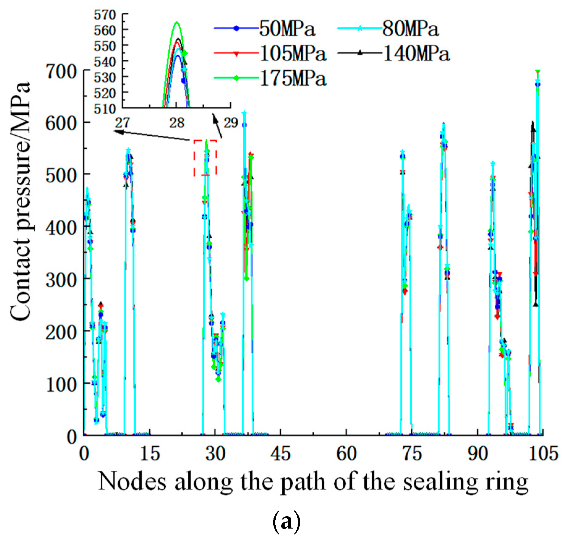
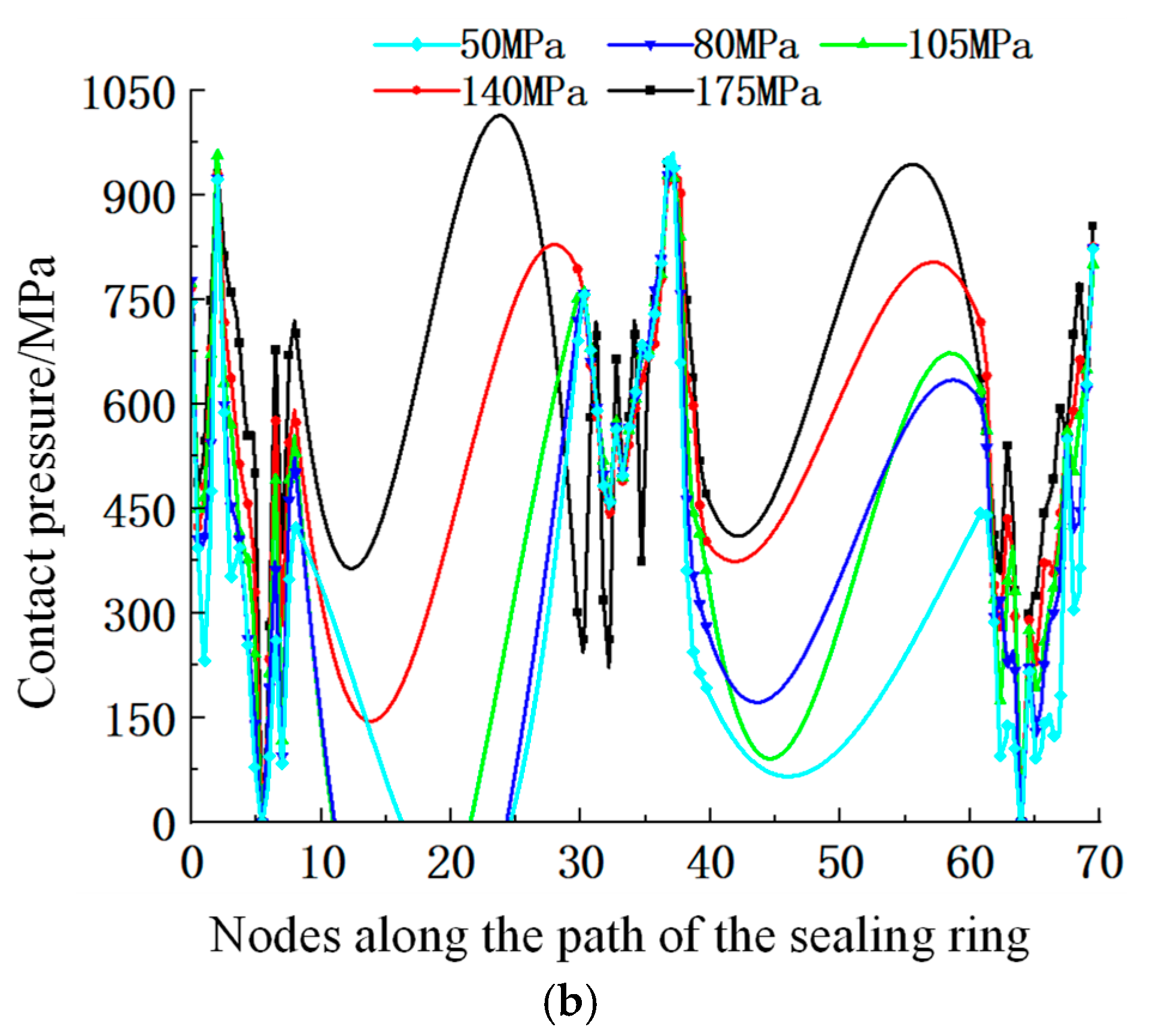
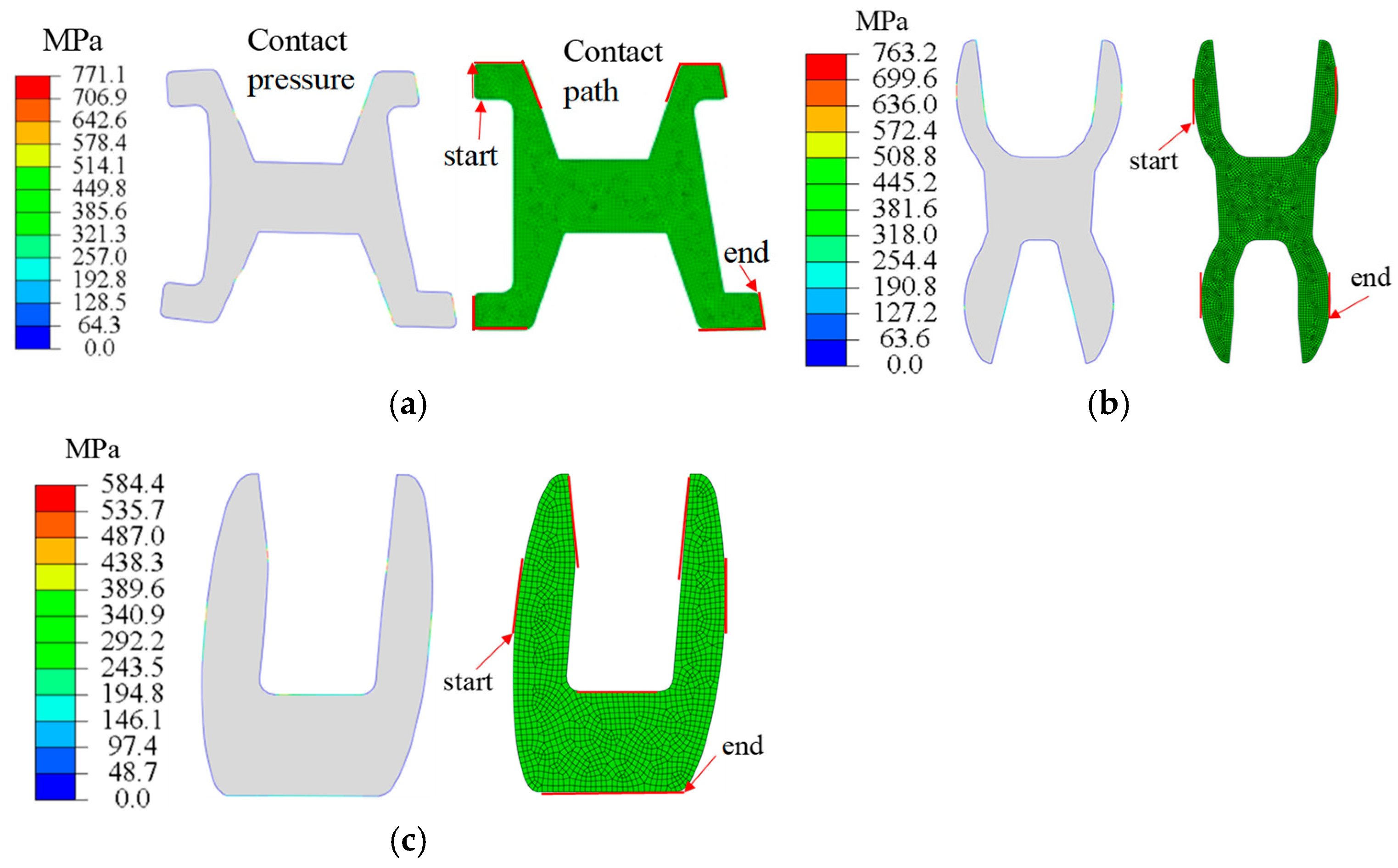
As shown in Figure 8, the overall stress of the straight U-shaped metal sealing ring is relatively small within the range of 50 MPa to 175 MPa. The maximum stress at the contact parts with the mandrel and the four-way is 316.1 MPa when the pressure is 175 MPa, and the stress at other parts is much less than the yield stress value. Figure 9 shows the contact path diagram of the sealing ring, and Figure 10a presents the contact curve of the X metal sealing ring. Under various loads, the peak value of the sealing contact pressure variation ranges from 540 MPa to 570 MPa, with a contact pressure difference of approximately 30 MPa. In Figure 10b, the contact pressure curve of the straight U-shaped metal sealing ring shows that the peak contact pressure of the seal is between 700 MPa and 1000 MPa. Therefore, the contact pressure of the straight U-shaped metal sealing ring fluctuates greatly, which is not conducive to the stability of the seal.

3.3. Analysis of Elliptical U-Shaped Metal Seal

The materials of the mandrel, four-way, and sealing parts are the same as mentioned above. Tensile loads F = 100 t–400 t are, respectively, applied to the lower end face of the mandrel, and pressure loads P = 50 MPa–175 Mpa are, respectively, applied to the upper end face of the sealing ring, as shown in Figure 11.
As shown in Figure 12, the X-shaped metal sealing ring and the double U-shaped metal sealing ring are subjected to air pressure. The maximum stress of the X-shaped metal sealing ring is 278.7 Mpa, and the X-shaped metal sealing ring undergoes plastic deformation when the upper load reaches 175 Mpa. Double U-shaped and single U-shaped sealing rings mainly bear the suspended load of the tube string. When the tensile load F is within the range of 100 tons to 400 tons, the stress of the double U-shaped and single U-shaped sealing rings varies within the range of 33 Mpa to 316.8 Mpa. The maximum stress is mainly in the middle, effectively forming a plastic contact surface, and the overall safety is relatively high. Under the maximum load and pressure conditions, this sealing system meets the load-bearing conditions.
As shown in Figure 13, the overall stress of the straight U-shaped metal sealing ring is relatively small within the range of 50 Mpa to 175 Mpal. The maximum stress at the contact parts with the mandrel and the four-way is 316.1 Mpa, and the stress at other parts is much less than the yield stress value when the pressure is 175 Mpa. Figure 14 shows the contact path diagram of the sealing rings, and Figure 13a shows the contact curve of the X metal sealing ring. The peak contact pressure of the seal ring is between 500 Mpa and 800 Mpa, and the contact pressure difference is approximately 300 Mpa. The contact pressure of the X-type metal sealing ring fluctuates greatly and its contact width is relatively small, which is not conducive to the stability of the seal ring. Figure 13b shows the contact pressure curve of the double U-shaped metal sealing ring. The peak contact pressure between the lower end side of the mandrel is between 220 Mpa and 275 Mpa, and the peak contact pressure between the contact part of the right side and the four-way is between 400 Mpa and 500 Mpa, with a relatively large contact width. Therefore, the contact pressure fluctuation of the single U metal sealing ring is relatively large, which is conducive to the stability of the seal ring. In Figure 13c, the contact pressure curve of the single U-shaped metal sealing ring shows that the peak contact pressure at the left part of the mandrel is between 200 Mpa and 600 Mpa, and the peak contact pressure at the right part of the four-way is between 200 Mpa and 400 Mpa when the pressure is 175 Mpa, which can effectively form a sealing ability of 175 Mpa. Therefore, the contact pressure fluctuations of double U and single U metal sealing rings are smaller, which is conducive to the stability of the seal.
Through finite element calculation, it was found that the mechanical properties and contact pressure of X-shaped and straight U-shaped metal seals fluctuate greatly among the four types of special-shaped metal seals, and their sealing widths are relatively small. The mechanical properties and sealing performance of ball-drum-type metal seals and elliptical U-shaped seals are relatively stable, and their contact widths are relatively large.

4. Research on Optimization of Seal Components of Hanger

The response surface method refers to the approximation of implicit limit state functions using polynomial functions through a series of deterministic experiments. By reasonably selecting test points and iterative strategies, it is ensured that the polynomial function can converge to the failure probability of the real implicit limit state function in terms of failure probability. The linear response surface has a relatively high approximation accuracy when the nonlinearity of the real limit state function is not significant. The response surface method can set multiple dependent variables at once, which is more efficient. Moreover, the response surface method can determine the optimal solution of the independent variable within its value range. Based on the three dependent variables, the response surface method can determine the best combination of independent variables, providing data support for actual production.
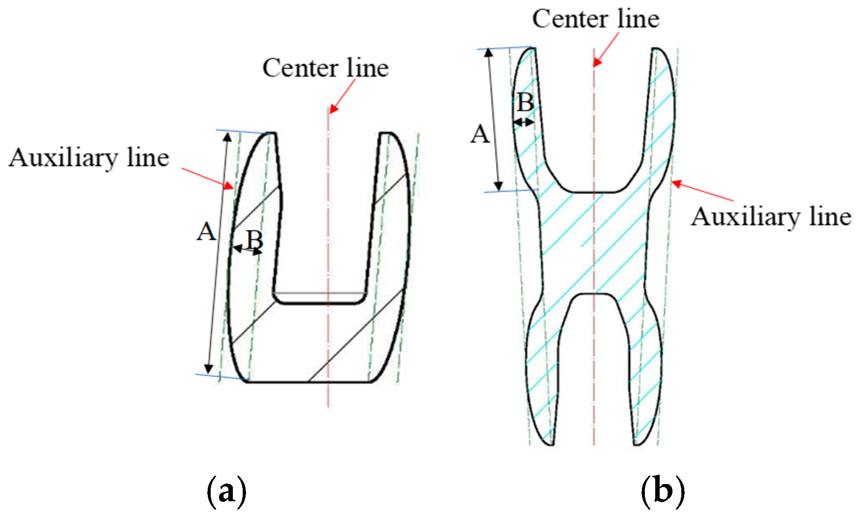
It Is found that the elliptical U-shaped sealing structure is preferred as the design intersection through analysis. To further analyze the influence of different metal sealing structure parameters on sealing performance, a comparative study of the parameters of the elliptical U-shaped metal structure is conducted. The key dimensions and parameters of each structure are shown in Figure 15. The key parameters of this metal structure mainly include the size and shape of the contact surface and the yield strength of the sealing parts. These parameters determine the values of contact pressure and stress. Based on the analysis of the key parameters of the elliptical U-shaped metal structure, the influence degree of the response factor acting together on the sealing effect of the hanger is obtained, providing a theoretical reference basis for the design and manufacture of the hanger.
In Figure 15a, A represents the length of the long axis of a single U-shaped ellipse (A = 18.5–23.5 mm), and B represents the length of the minor axis of a single U-shaped ellipse (B = 3.5–4.5 mm). In Figure 15b, A represents the length of the long axis of the double U-shaped ellipse (A = 18.5–21.5 mm), and B represents the length of the minor axis of the double U-shaped ellipse (B = 3.8–4.8 mm). The yield strength range of each metal seal ring is C (C = 270–350 MPa).
The optimization objective function of the key parameters of this metal sealing structure is
M a x C p M i n σ
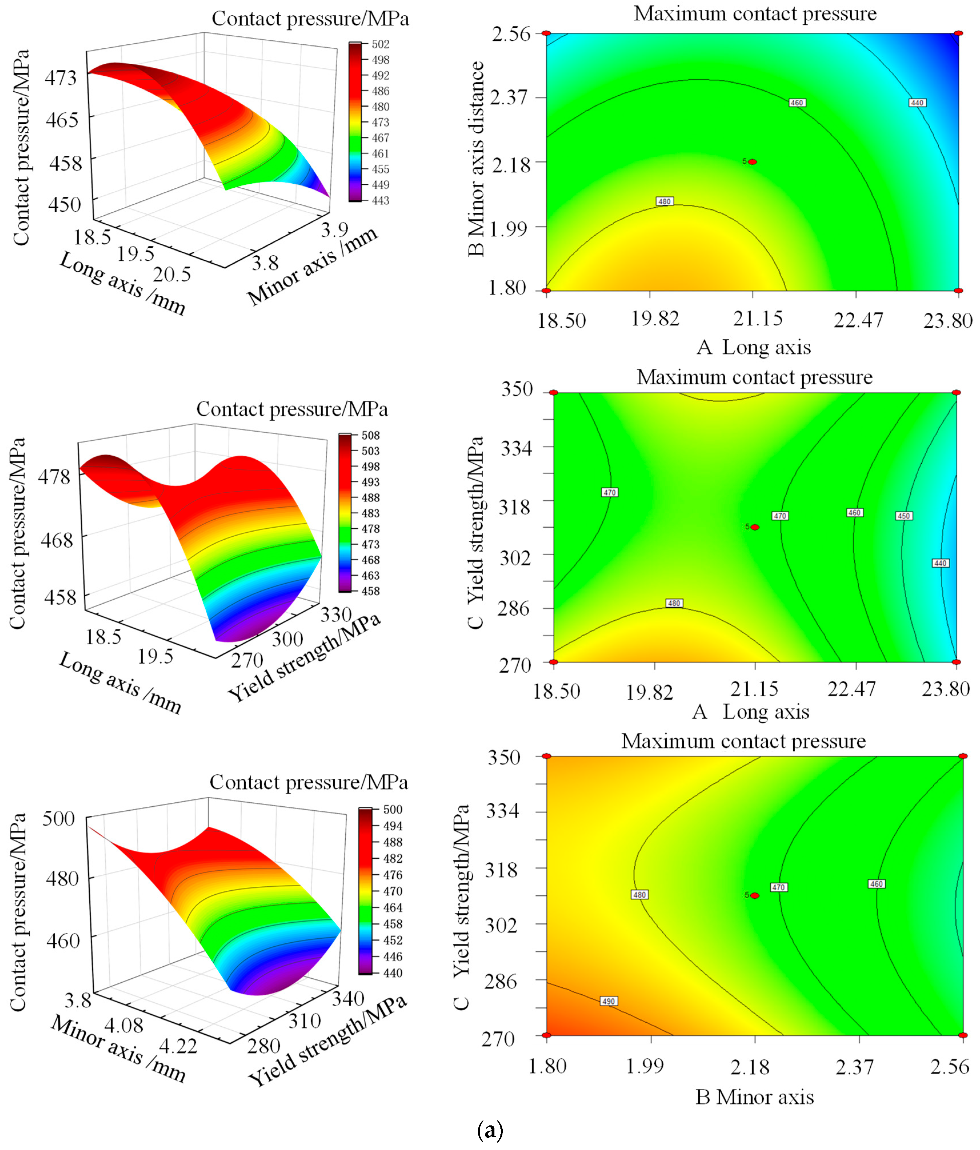
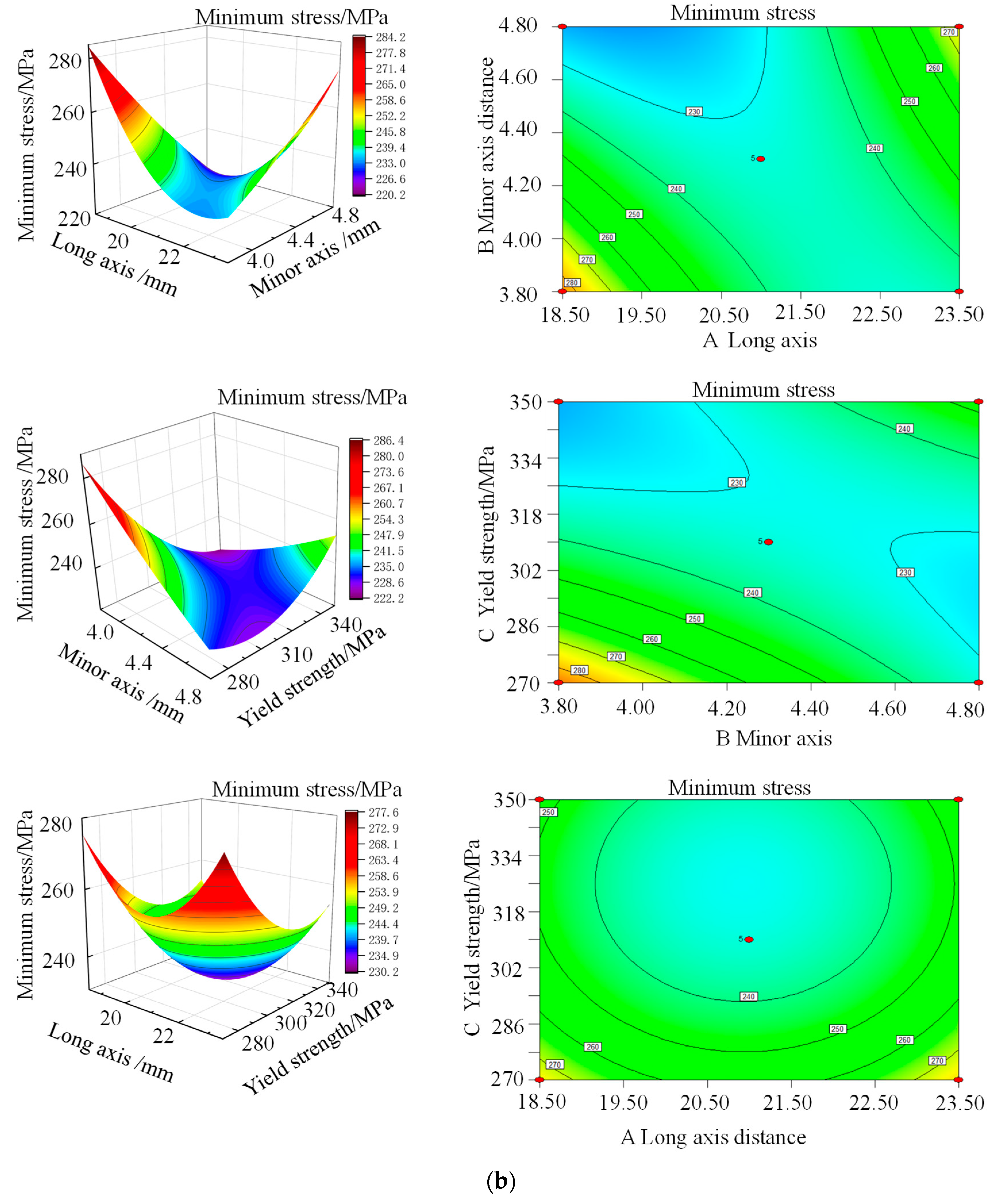
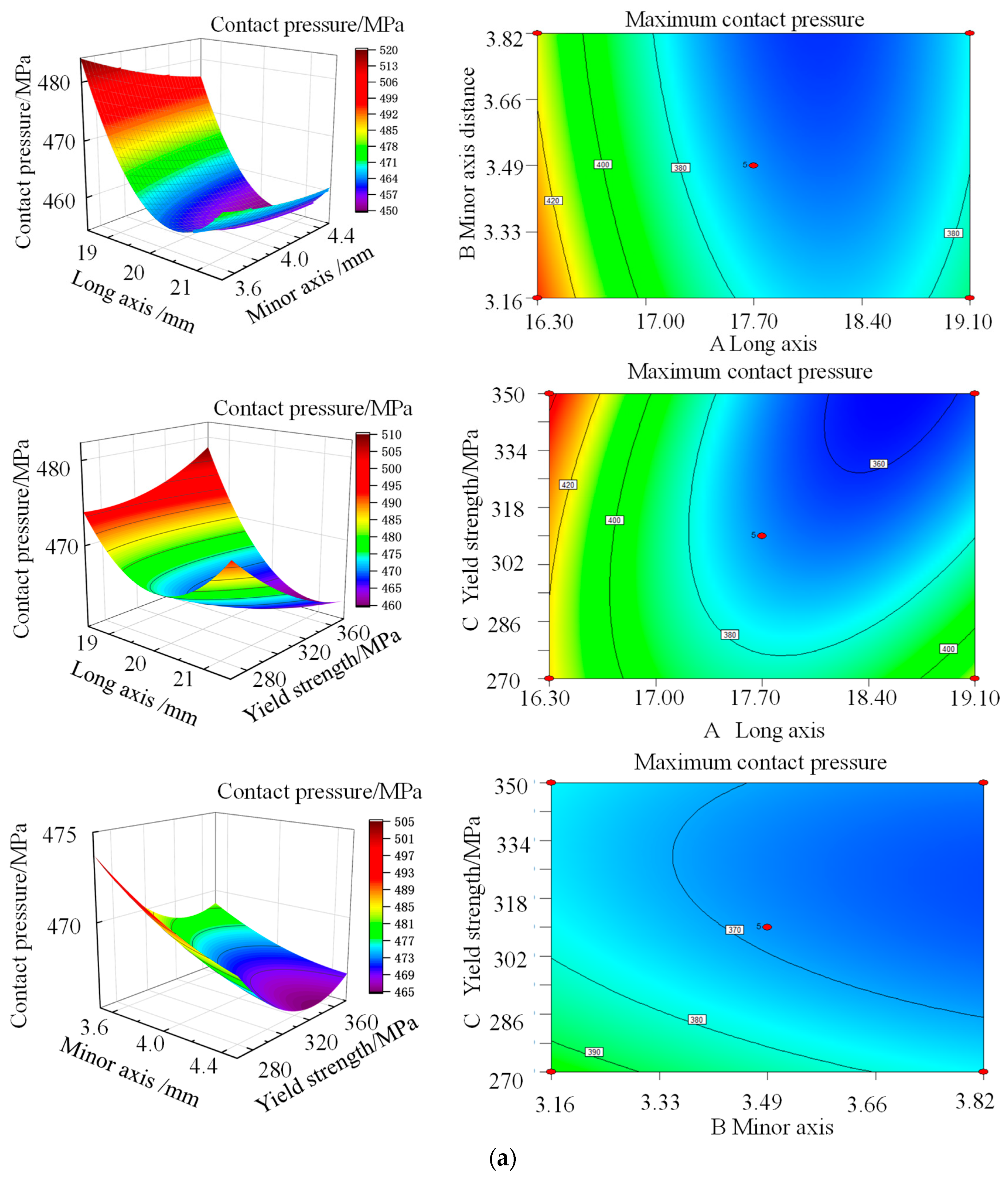
In the formula, Cp represents the maximum contact pressure, in Mpa. σ is the minimum von Mises stress, in Mpa. According to the mutual influence law of the key structural parameters of each sealing part, the response surface diagrams of the maximum contact pressure and the minimum von Mises stress were obtained, as shown in Figure 16 and Figure 17.
Figure 16a shows the variation trend of the contact pressure of a single U-shaped sealing ring under different structural parameters. As the influence factors A and B gradually increase, the contact pressure between the sealing ring and the sealing surface shows a slow downward trend, indicating that the increase in structural dimensions weakens the tightness of the sealing interface to a certain extent. The influence of the variation in the yield strength of the material exhibits more complex nonlinear characteristics: in the initial stage, the rigidity of the material intensifies as the yield strength increases, resulting in a decrease in its elastic deformation capacity during assembly, thereby reducing the contact pressure. However, the material’s ability to resist plastic deformation significantly improves when the yield strength further increases by 315.4 MPa, and thus the contact pressure rises accordingly. Within the range of parameters studied, the maximum contact pressure at the sealing interface reaches 512.6 Mpa when the long axis distance is 20.56 mm and the short-axis distance is 3.94 mm.
It is found that the minimum stress on the outside of the sealing ring first decreases and then increases with the increase in the long axis distance in Figure 16b, and slowly decreases with the increase in the short-axis distance. Although the material parameters have a relatively small impact on the equivalent effect force changes, from the perspective of overall sealing performance, appropriately increasing the yield limit can help improve the adhesion and adaptability of the sealing interface, thereby enhancing the sealing effect. If the long axis distance is too large, it will cause the contact pressure distribution to be overly dispersed, reducing the sealing reliability. Therefore, in the optimization design, the matching relationship of the three structural parameters needs to be comprehensively considered to achieve the best sealing performance.
It is found that the performance of the double U-shaped metal sealing ring is obvious in Figure 17a. The contact pressure of the double U-shaped metal sealing ring first drops sharply and then rises slowly when the long axis distance increases. The contact pressure decreases slowly when the short-axis distance increases. However, the influence of material parameters on contact pressure is relatively small. It is found that there is a significant compound relationship in the influence of the three factors on the contact pressure in Figure 17b. With the increase in the long axis and the short axis, the minimum contact pressure first decreases and then increases. The equivalent stress reaches the minimum value when the long axis is 19.86 mm and the short axis is 4.15 mm.
Binary regression analysis was conducted using response surface curves, with max [Cp] and min [σ] as the targets. After parameter optimization, the comparison results are shown in Table 1.
As shown in Table 1, the performance differences between single U-shaped and double U-shaped sealing rings before and after optimization are significant, and the optimization effect is obvious. Specifically, for the single U-shaped sealing structure, the optimization rates of the maximum contact pressure (max [Cp]) and the minimum equivalent stress (min [σ]) reached 11.63% and 10.63%, respectively. For the double U-shaped structure, the optimization rates of both the maximum contact pressure and the minimum equivalent stress exceed 12%, demonstrating superior structural response characteristics. Furthermore, the errors generated during the optimization process were all controlled within an acceptable range. The results show that the adopted optimization method can effectively improve the key performance indicators of the sealing structure and has good engineering application value.

5. Experimental Study on the Sealing Structure of the Hanger

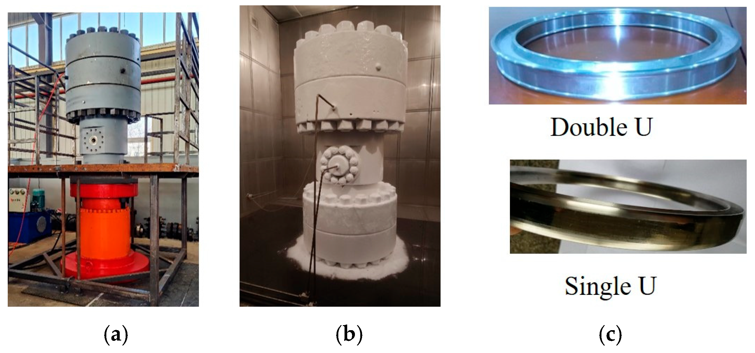
In order to meet the on-site requirements for 175 Mpa high-pressure gas sealing, gas sealing tests on the 8 1/8 “elliptical surface U-shaped sealing structure were conducted. Figure 18a and b, respectively, show the indoor test photos of the new metal-sealed hanger device, and Figure 18c shows the photo of the new metal-sealed component.
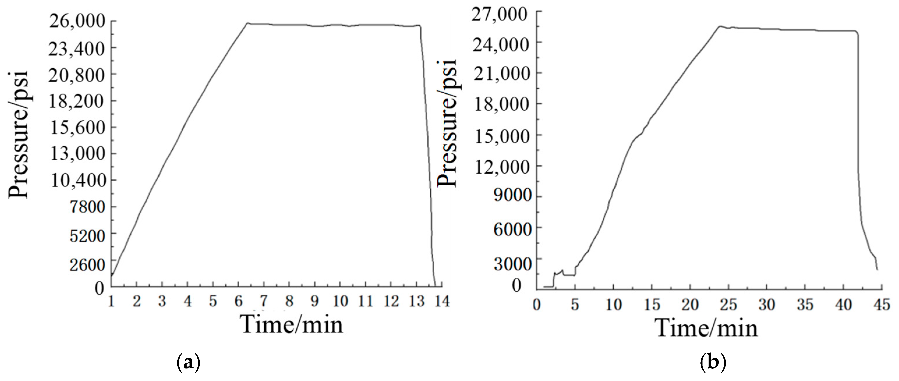
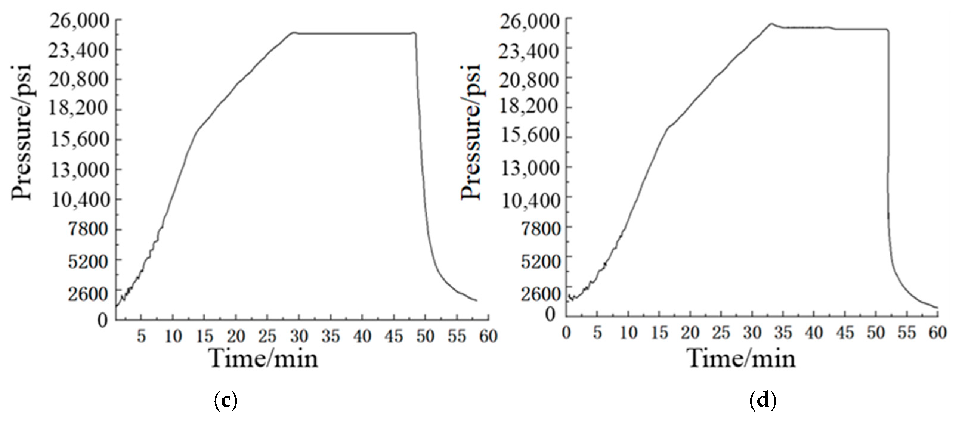
Figure 19a shows the first pressure test. The test pressure was 180.58 MPa, and it was stabilized for 3 min with a pressure drop of 1.09 Mpa. Figure 19b shows that the pressure in the second test was 176.25, and it was stabilized for 15 min with a pressure drop of 0.5 Mpa. Figure 19c shows that the pressure in the third test was 176.25, and it was stabilized for 15 min with a pressure drop of 2.05 Mpa. Figure 19d shows that the pressure in the fourth test was 176.2, and it was stabilized for 15 min with a pressure drop of 0.57 Mpa. From the pressure test curve, it was found that the average pressure drop was all less than 1.5 Mpa, and the pressure was stable. The test indicated that the metal sealing structure met the requirements of 175 Mpa air pressure sealing.

6. Conclusions

Through simulation optimization comparison and experimental research, the following conclusions have been drawn:
(1)
The peak contact pressure of the double U-shaped metal sealing ring is between 220 MPa and 275 MPa, and the peak contact pressure between the contact part of the right side and the four-way is between 400 MPa and 500 MPa, with a relatively large contact width. And it can effectively seal a gas pressure of 175 MPa.
(2)
It was found that the mechanical properties and contact pressure of X-shaped and straight U-shaped metal seals fluctuate greatly among the four types of special-shaped metal seals, and their sealing widths are relatively small. The mechanical properties and sealing performance of ball-drum metal seals and elliptical U-shaped seals are relatively stable, and their contact widths are relatively large.
(3)
The material’s ability to resist plastic deformation significantly improves when the yield strength further increases by 315.4 MPa, and thus the contact pressure rises accordingly. Within the range of parameters studied, the maximum contact pressure at the sealing interface reaches 512.6 MPa when the long axis distance is 20.56 mm and the short-axis distance is 3.94 mm. The analysis results show that this combination of structural parameters can enhance the sealing performance.
(4)
The contact pressure of the double U-shaped metal sealing ring first drops sharply and then rises slowly when the long axis distance increases. The contact pressure decreases slowly when the short-axis distance increases.
(5)
For the single U-shaped sealing structure, the optimization rates of the maximum contact pressure and the minimum equivalent stress reached 11.63% and 10.63%, respectively. For the double U-shaped structure, the optimization rates of both the maximum contact pressure and the minimum equivalent stress exceed 12%, demonstrating superior structural response characteristics.
(6)
During the four indoor tests, the pressure stabilization time was basically 15 min, and the average pressure drop was less than 1.5 MPa. The pressure was stable. The tests indicated that the metal sealing structure met the requirements of 175 MPa air pressure sealing.

Author Contributions

Conceptualization, J.W. (Jianfei Wang) and S.F.; methodology, J.W. (Junhui Wei); software, K.L.; validation, S.F., L.Z. and S.F.; formal analysis, F.L.; investigation, L.Z.; resources, J.W. (Jianfei Wang); data curation, L.Z. and Z.J.; writing—original draft preparation, J.W. (Jianfei Wang); writing—review and editing, S.F. and K.L.; visualization, J.W. (Junhui Wei); supervision, L.Z.; project administration, F.L.; funding acquisition, J.W. (Jianfei Wang) and S.F. All authors have read and agreed to the published version of the manuscript.

Funding

This research was funded by the research and development of ultra-high-pressure wellhead and supporting equipment (grant number 2015ZG15). And the APC was funded by the Major Science and Technology Project of China National Petroleum Corporation.

Data Availability Statement

The original contributions presented in this study are included in the article. Further inquiries can be directed to the corresponding author.

Acknowledgments

The authors are grateful for the financial support from the research and development of ultra-high-pressure wellhead and supporting equipment (2015ZG15) of the Major Science and Technology Project of China National Petroleum Corporation.

Conflicts of Interest

Authors Jianfei Wang, Lijin Zhu, Zhenyu Jia and Fudong Liu were employed by Bohai Equipment Manufacturing Co., Ltd.; Authors Shaobo Feng, Kun Li and Junhui Wei were employed by PetroChina Tarim Oilfield Company. The remaining authors declare that the research was conducted in the absence of any commercial or financial relationships that could be construed as a potential conflict of interest. The Bohai Equipment Manufacturing Co., Ltd. and PetroChina Tarim Oilfield Company had no role in the design of the study; in the collection, analyses, or interpretation of data; in the writing of the manuscript, or in the decision to publish the results.

References

  1. Lian, Z.; Wan, Z.; Wu, Y.; Shi, J.; Zhao, Z. Finite element analysis on mechanical strength of casing at slip hanger in ultra-deep wells. China Pet. Mach. 2023, 51, 1–8. [Google Scholar] [CrossRef]
  2. Zhang, Z.; Sang, P.; Sang, Z.; Hou, D.; Lv, Y.; Zheng, Y.; Zhang, C. Analyzing failure of casing head slip hanger. Eng. Fail. Anal. 2020, 108, 104301. [Google Scholar] [CrossRef]
  3. Zhang, L.; Zhang, L.; Liang, W. Casing safety evaluation for setting liner hanger. J. Nat. Gas Sci. Eng. 2014, 19, 58–61. [Google Scholar] [CrossRef]
  4. Liu, Y. Study on Design Mechanism and Test of Full-Metal Sealing Structure of Mandrel-Type Hanger of High Pressure Gas Well; Southwest Petroleum University: Chengdu, China, 2020. [Google Scholar] [CrossRef]
  5. Liu, Y.; She, Y.; Lian, Z.; Yi, X. Structural Design and Evaluation of High Strength Thread of Mandrel Hanger. J. Southwest Pet. Univ. (Sci. Technol. Ed.) 2024, 46, 159–169. [Google Scholar] [CrossRef]
  6. Liu, Y.; Lian, Z.; Zhang, J.; Zhou, J.; Wang, F. Research on metal seal structure of large diameter mandrel hanger. Lubr. Eng. 2022, 47, 124–131. [Google Scholar] [CrossRef]
  7. Liu, Y.; Lian, Z.; Shi, T.; Sang, P. Fracture failure analysis and research on slip of casing head. Eng. Fail. Anal. 2019, 97, 589–604. [Google Scholar] [CrossRef]
  8. Liu, Y.; Lian, Z. Failure analysis on rubber sealing structure of mandrel hanger and improvement in extreme environments. Eng. Fail. Anal. 2021, 125, 105433. [Google Scholar] [CrossRef]
  9. Liu, Y.; She, Y.; Li, W. Research on Working Mechanism and Structural Optimization of High-Speed Bearing of Tricone Bits Based on Finite Difference Method. J. Tribol. 2025, 147, 044103-1. [Google Scholar] [CrossRef]
  10. Liu, Y.; Lian, Z.; Deng, C.; Zhang, Q.; Mu, Y. Design and experimental study on full-metal sealing structure of mandrel-type casing hanger. Adv. Mech. Eng. 2019, 11, 168781401984625. [Google Scholar] [CrossRef]
  11. Patel, H.; Salehi, S.; Teodoriu, C.; Ahmed, R. Performance evaluation and parametric study of elastomer seal in conventional hanger assembly. J. Pet. Sci. Eng. 2019, 175, 246–254. [Google Scholar] [CrossRef]
  12. Patel, H.; Salehi, S.; Ahmed, R.; Teodoriu, C. Review of elastomer seal assemblies in oil & gas wells: Performance evaluation, failure mechanisms, and gaps in industry standards. J. Pet. Sci. Eng. 2019, 179, 1046–1062. [Google Scholar] [CrossRef]
  13. Ahmed, S.; Salehi, S.; Ezeakacha, C. Review of gas migration and wellbore leakage in liner hanger dual barrier system: Challenges and implications for industry. J. Nat. Gas Sci. Eng. 2020, 78, 103284. [Google Scholar] [CrossRef]
  14. Wang, Z.; Zhang, H.; Zhao, Y.; Feng, D.; Tu, Y. Optimization Design for K-Shaped Metal Seal Structure Based on Response Surface Method. China Pet. Mach. 2022, 50, 80–85. [Google Scholar] [CrossRef]
  15. Tian, Y.; Ju, Y.; Pu, X.; Lv, H.; Zhao, Y.; Feng, D. Simulation Analysis of Sealing Characteristics of K-Shaped Metal Ring on Tube Hanger. China Pet. Mach. 2021, 49, 81–88. [Google Scholar] [CrossRef]
  16. Wang, Y.; Zou, S.; Liu, Y.; Wang, Y.; Fu, Z.; Chen, K.; Li, H. Research on seal structure design of marine casing hanger of high pressure. Valve 2023, 2, 133–135. [Google Scholar] [CrossRef]
  17. Wang, F.; Zheng, Z.; Liu, L.; Deng, Q.; Li, W.; Tian, F.; Zhou, J.; Li, R. Design and Performance Analysis of Mandrel Hanger Metal Sealings. Oil Field Equip. 2024, 53, 59–64. [Google Scholar] [CrossRef]
  18. Feng, C.; Li, A.; Chen, X.; Du, W.; Luo, X. Metal seal of tube hanger in ultra-high pressure gas wells. China Pet. Mach. 2025, 53, 102–108+131. [Google Scholar] [CrossRef]
  19. Cirimello, P.; Otegui, J.L.; Aguirre, A.; Carfi, G. Undetected non-conformities in material processing led to a service failure in a casing hanger during pre-fracture operation. Eng. Fail. Anal. 2019, 104, 203–215. [Google Scholar] [CrossRef]
  20. Peng, J.; Li, M.; Liu, F.; Guo, C.; Wei, C.; Li, Y. Analysis and optimization design of sealing performance of different linear flange surfaces of high pressure casing hanger. Lubr. Eng. 2024, 49, 141–149. [Google Scholar] [CrossRef]
  21. Ren, G.; Zhang, C.; Chen, C.; Wang, Y.; Zhang, H.; Feng, D. Research on the Sealing Performance of U-Shaped Metal Ring for Tube Hanger. Oil Field Equip. 2022, 51, 18–25. [Google Scholar] [CrossRef]
  22. Lian, Z.; Liu, Y.; Zhang, Y.; Yan, Y.; Wang, Y. Design and study on metal seal of casing mandrel hanger. Lubr. Eng. 2019, 44, 115–120. [Google Scholar] [CrossRef]
  23. Liu, Y.; Qian, L.; Zou, J.; Xia, C.; Lian, Z. Study on failure mechanism and sealing performance optimization of compression packer. Eng. Fail. Anal. 2022, 136, 106176. [Google Scholar] [CrossRef]
  24. Huang, X.; Xu, T.; Liu, Y. Experimental and thermal-structure coupling analysis for oil and water-swellable packer. Energy Sci. Eng. 2023, 11, 3055–3069. [Google Scholar] [CrossRef]
  25. Liu, Y.; Qian, L.; Xia, C.; Yi, X. Design and experimental study on a novel sealing structure of rotary control head for coalbed methane underbalanced drilling. Eng. Fail. Anal. 2022, 139, 106441. [Google Scholar] [CrossRef]
  26. Liu, Y.; Qian, L.; Xia, C.; Yi, X.; Lian, Z. Failure Analysis of Ram Body and Sealing Performance of Semi-Sealed Blowout Preventer. J. Fail. Anal. Prev. 2022, 22, 1011–1030. [Google Scholar] [CrossRef]
  27. Liu, Y.; Li, W.; Xia, C. Research on sealing mechanism and structural improvement of metal sealing structures for high speed drill bits. Int. J. Press. Vessel. Pip. 2024, 207, 105104. [Google Scholar] [CrossRef]
  28. Liu, Y.; Qian, L.; Xia, C.; Zou, J.; Lian, Z.; Yi, X. Failure analysis and structural optimization of rubber core and support rib of full-size spherical blowout preventer. Eng. Fail. Anal. 2023, 143, 106865. [Google Scholar] [CrossRef]
Figure 1. Failure photos of the mandrel-type tube hanger before and after use. (a) Before use. (b) After use.
Processes 13 02970 g001
Figure 2. Assembly drawing and physical photo of the ultra-high-pressure tube head. (a) Assembly drawing. (b) Physical photo.
Processes 13 02970 g002
Figure 3. Four types of oil casing hangers and sealing structures. (a) Ball drum. (b) X-shaped and straight U-shaped. (c) Elliptical U-shaped.
Processes 13 02970 g003
Figure 4. Assembly drawing of the sealing structure and the finite element model. (a) Solid model. (b) Force model. (c) Finite element model.
Processes 13 02970 g004
Figure 5. Stress contours of ball-drum seal structures under different loads.
Processes 13 02970 g005
Figure 6. Contact path and contact pressure variation curve of the sealing ring. (a) Contact path selection. (b) Contact pressure variation curve graph.
Processes 13 02970 g006
Figure 7. The assembly drawing of the sealed structure and the finite element model. (a) Assembly drawing of sealed structure. (b) The finite element model. (c) The enlarged image.
Processes 13 02970 g007
Figure 8. Stress contours of X-shaped and straight U-shaped metal sealing rings.
Processes 13 02970 g008
Figure 9. Selection of contact paths for two types of metal sealing rings. (a) X-type. (b) Straight U-type.
Processes 13 02970 g009
Figure 10. Contact pressure variation curves of the metal sealing rings. (a) X-type. (b) Straight U-type.
Processes 13 02970 g010aProcesses 13 02970 g010b
Figure 11. The assembly drawing of the sealing structure and the finite element model.
Processes 13 02970 g011
Figure 12. Stress diagram of the metal sealing ring.
Processes 13 02970 g012
Figure 13. Contact pressure variation curve of all-metal sealing rings. (a) X-shaped. (b) Double U-shaped. (c) Single U-shaped.
Processes 13 02970 g013
Figure 14. Selection of contact path for sealing rings. (a) X-shaped. (b) Double U-shaped. (c) Single U-shaped.
Processes 13 02970 g014
Figure 15. Structural Parameters of the elliptical U-shaped metal sealing ring. (a) Single U-shaped. (b) Double U-shaped.
Processes 13 02970 g015
Figure 16. Response surface of objective function and the design variable of the single U-shaped. (a) Response surface diagram of contact pressure. (b) Response surface diagram of the minimum equivalent stress.
Processes 13 02970 g016aProcesses 13 02970 g016b
Figure 17. Response surface of objective function and the design variable of the double U-shaped. (a) Response surface diagram of contact pressure. (b) Response surface diagram of the minimum equivalent stress.
Processes 13 02970 g017aProcesses 13 02970 g017b
Figure 18. Test photos of the new type of metal seal. (a) Indoor test. (b) Field test. (c) U-shaped sealing ring.
Processes 13 02970 g018
Figure 19. Four-test pressure curve (25,000 psi = 175 MPa). (a) The first test. (b) The second test. (c) The third test. (d) The fourth test.
Processes 13 02970 g019aProcesses 13 02970 g019b
Table 1. Comparative analysis of optimization results.
CategoryOriginal/MPaOptimization/MPaErrorOptimization Rate
max [Cp]/single U569.3502.32.45%11.63%
max [Cp]/double U584.8511.41.83%12.55%
min [σ]/single U297.6265.64.69%10.63%
min [σ]/double U329.7287.53.52%12.78%
Disclaimer/Publisher’s Note: The statements, opinions and data contained in all publications are solely those of the individual author(s) and contributor(s) and not of MDPI and/or the editor(s). MDPI and/or the editor(s) disclaim responsibility for any injury to people or property resulting from any ideas, methods, instructions or products referred to in the content.