Article

Low-Carbon, High-Efficiency, and High-Quality Equipment Selection for Milling Process Based on New Quality Productivity Orientation

College of Optical, Mechanical and Electrical Engineering, Zhejiang A&F University, Hangzhou 311300, China
*
Author to whom correspondence should be addressed.
Processes 2025, 13(9), 2935; https://doi.org/10.3390/pr13092935
Submission received: 14 August 2025 / Revised: 1 September 2025 / Accepted: 4 September 2025 / Published: 14 September 2025

Abstract

Selecting appropriate milling equipment is an important means to reduce carbon emissions and improve the efficiency of part-machining processes, as the process of machining the same part on different milling machines varies greatly. Traditional milling machine selection approaches only involve a static analysis of their advantages and disadvantages without considering the dynamic changes in the production process, making them difficult to adapt to the requirements of the new era. To solve this problem, we establish a milling machine selection model based on the new quality productivity (NQP) concept; propose a calculation method considering carbon emissions, efficiency, and quality (expressed as surface roughness) in the production process; and quantitatively analyze the process objectives of different milling machines according to the changes in the machining process. The spindle speed, feed rate, cutting width, and cutting depth are taken as the optimization variables, and the cutting parameters are optimized using the egret swarm algorithm (ESA) to obtain the Pareto frontier solutions providing low-carbon and high efficiency process parameters. The method was verified through a plane milling example. After ESA optimization, the processing time was increased by 5.6%, the surface roughness accuracy was improved by 12.9%, and the carbon emissions were reduced by 13.1%, demonstrating the effectiveness of the proposed method.

1. Introduction

With the continuous development of science and technology, the global economy has undergone profound changes. New quality productivity (NQP), as a novel production mode, is increasingly becoming an important force in the construction of modern industrial systems [1,2]. New quality productivity promotes technological innovation, intelligence, and greenness, which are significant characteristics for improving efficiency and competitiveness in industrial production [3,4,5] and promoting optimization and upgrading of the industrial structure. NQP is particularly critical for improving the greenness of parts processing enterprises [6].
Optimizing the selection of machine tools is an effective way to enhance greenness in such enterprises. Under the premise of meeting production process requirements, enterprises are usually faced with a variety of operational machine tool equipment solutions. There are differences between machine tools regarding their part-processing quality, time quota, cost, energy consumption, and noise pollution, etc. [7]. Therefore, the rational selection of processing equipment and techniques not only enhances the economic benefits of enterprises, but may also promote their sustainable development and long-term economic growth [8]. Some classic methods for selecting machine tools and equipment include combining the Analytic Hierarchy Process (AHP) with fuzzy evaluation and other methods for evaluation [9,10]. In this way, considering factors such as the processing time, quality, cost, resource consumption, and environment, equipment optimization can be carried out. Correspondingly, evaluation systems for machine tool selection indicators have been established based on relevant methods such as the grey relational degree [11]. These classic approaches for selecting machine tools do not consider issues such as carbon emissions, only taking qualitative aspects of equipment selection into account without conducting quantitative analysis. With the development of intelligent manufacturing, scholars have conducted in-depth research and incorporated elements of intelligence into the process of machine tool selection.
Yan et al. [12] established a measurable and quantifiable evaluation index system and decision model for the optimization and evaluation of machine tool equipment in the context of intelligent manufacturing. Based on the RIM method, a comprehensive evaluation model for optimal selection of intelligent machine tools was calculated and solved, and a case study was carried out. Aiming at the difficult problem of machine tool equipment resources in manufacturing, Önüt S et al. [13] introduces a fuzzy technology, which is used to prioritize orders through a method similar to TOPSIS, which is used to evaluate and select the vertical CNC machining center of a manufacturing company in Istanbul, Turkey. Zhao et al. [14] used the TOPSIS method to construct an evaluation model for a machining process scheme based on low-carbon manufacturing, considering the compatibility of resources and environmental considerations while maximizing economic benefits. Through actual cases of manufacturing enterprises, the low-carbon manufacturing process scheme was evaluated comprehensively and the feasibility of the evaluation model was verified. Klink et al. [15] studied grinding, EDM, laser machining, and milling manufacturing techniques, comparing the different manufacturing processes using an example of a mold cavity defined by hardened and tempered cold working steel 45NiCrMo16. Comparing the processing costs, grinding was found to be optimal, followed by sinking EDM, milling, and finally laser. Ana et al. [16] proposed a simulation model using a genetic algorithm to determine the optimal process parameters and machine tool configuration. In the decision stage of machine selection the goal of profit per unit is the highest possible target, which is ensured by optimizing the values of the following variables: SPM configuration, machining unit allocation for each group, and all feed and cutting speeds. Hai et al. [17] proposed an energy-saving optimization method that considers the selection and sequence of machine tools in a flexible job shop. A mathematical model was established using the mixed integer programming method, and the energy consumption target was combined with the maximum completion time target. This method was verified with a workshop processing case. Zanuto et al. [18] evaluated the resource consumption and environmental impacts over the entire life cycle of different processing techniques to select washing and shaving processes for equipment, aiming to optimize the washing and shaving strategies to minimize the environmental impact. Their results indicated that the average-sized milling machine had a greater impact than the micro-milling machine, low speed had a greater impact than high speed, and the use of high-speed steel tools had a greater impact than the use of hard alloy tools. Zhang et al. [19] used fuzzy mathematical theory to establish a theoretical model for optimal machine tool selection considering geometric features, clamping size, machining range, machining accuracy, and surface roughness. The automatic selection of machine tools was realized using a generative computer-aided process planning (CAPP) system.
In modern manufacturing, the processing of the same product can be accomplished using multiple types of complex machine tools. Under the premise of meeting product quality and production process requirements, there are significant differences in carbon emissions and time consumption between different machine tools. Therefore, the selection of machine tools and equipment becomes a complex decision-making problem involving multiple objectives and schemes. From the perspective of actual production, when enterprises choose processing equipment, they mostly rely on subjective qualitative analyses based on experience. Although this qualitative approach can play a certain role in developing high-performance systems, due to the lack of accurate and quantified data support, it is difficult to comprehensively and precisely assess the performance of different equipment regarding key indicators such as carbon emissions and processing times. As a result, such an approach cannot provide a solid and reliable data basis for equipment selection, preventing enterprises from achieving efficient and green production. Relevant research focuses on the establishment of mathematical models related to variables and quality parameter optimization methods. A variety of intelligent optimization algorithms have been widely applied for the optimization of numerical control cutting parameters to reduce unit production costs. These algorithms include the genetic algorithm (GA) [20], simulated annealing algorithm (SAA) [21], and distributed search algorithm (DSA) [22], etc. However, these methods mainly focus on economic benefits and neglect processing quality, often resulting in the phenomenon of neglecting one aspect for the sake of another, thus limiting their effectiveness in practical applications. Product quality, efficiency, and energy consumption are usually in competition with each other; for instance, the development of high-quality products significantly reduces efficiency, leading to higher energy consumption. Therefore, single-objective optimization algorithms still have certain limitations [23].
In response to the above problems, this study innovatively constructs a production equipment selection model based on the NQP concept. This model comprehensively considers multiple key factors in the production process; in particular, to enhance the energy utilization rate of the CNC machining process and reduce the carbon emissions of the milling process, based on an energy consumption analysis, carbon emissions, processing time, and surface roughness are taken as optimization goals, while the spindle speed, feed rate, and cutting depth of the machine tool are considered as optimization variables. An energy consumption model for CNC milling machines enabling carbon emissions and processing time optimization was established. Through a detailed analysis and precise calculation of the production process parameters, the two important indicators of carbon emissions and processing time are quantitatively presented.
To further optimize the carbon emissions and processing time for the same product processed on different equipment, we introduce the egret swarm optimization algorithm, which simulates the foraging behavior of egret populations. When solving complex decision-making problems such as the selection of machine tools and equipment, this algorithm achieves optimization through the coordinated effect of its core strategies: the waiting strategy, the aggressive strategy, the discriminant condition, and dynamic selection. Compared with traditional multi-objective optimization algorithms [24] (such as NSGA-II, MOEA) and the particle swarm optimization (PSO) algorithm, the ESA has stronger global search ability. Through a random search based on aggressive strategies and gradient estimation of Egret A, it can explore the solution space more thoroughly. The ESA has more efficient convergence performance and is highly adaptable, with the waiting strategy of the algorithm utilizing historical information to accelerate local convergence. Meanwhile, there is no need for preset parameters such as crossover and mutation probabilities. The search behavior is automatically adjusted through an adaptive step size and dynamic selection mechanism, making it suitable for dynamic environments. Thus, the ESA provides strong support to obtain the optimal parameters for different equipment regarding carbon emissions and processing time.

2. Equipment Selection Model Based on NQP

2.1. New Quality Productivity

The NQP concept is motivated by the capacity of technological innovations to break through the growth paradigm of “high input, low efficiency, and extensive” under the traditional industrialization model, enabling the construction of new production systems characterized by intelligence, greenness, and service orientation [25,26]. The essence of NQP lies in achieving the optimization and reorganization of production factors and a qualitative leap in total productivity factors through the tripartite collaborative innovation of technology, system, and talent (as shown in Figure 1). Specifically, NQP is characterized by high technological density (e.g., digital twins and artificial intelligence algorithms), high efficiency levels (e.g., adaptive optimization of dynamic cutting parameters), and high-quality outputs (e.g., zero-defect processing and full life cycle reliability), giving rise to five development paradigms. The innovation-driven paradigm, taking the multi-objective collaborative control technology for the optimization of machine tool cutting parameters as an example, breaks through the traditional processing bottleneck that relies on experience by constructing a closed-loop system of “process database–real-time monitoring–intelligent decision making.” The coordinated development paradigm achieves spatial balance in the processing process and resource allocation based on digital twin technology; for example, by optimizing the capacity matching of multi-process machine tools through virtual simulation. The green and sustainable paradigm integrates the concept of low-carbon manufacturing into the design of cutting parameters, such as optimizing the spindle speed and feed rate using the Minimum Energy Consumption (MEC) model. The open symbiotic paradigm integrates high-quality resources (e.g., global tool wear prediction models) through industrial Internet platforms, promoting cross-border collaborative innovation in processing technology knowledge. The shared and inclusive model utilizes blockchain technology to build a decentralized process knowledge-sharing network, reducing the cost of cutting parameter optimization for small- and medium-sized enterprises by more than 40% [27]. As technology improves, the obtained results can be continuously optimized. In the field of machine tool processing, the practical path of NQP can be quantified as the dynamic optimization of cutting parameters; for instance, in traditional processing, the spindle speed (n), feed rate (f), and cutting depth (ap) are set based on the engineer’s experience. Meanwhile, intelligent optimization systems based on the NQP framework can perceive state variables such as cutting force, vibration, and temperature in real-time through multi-physics coupling models. Then, using reinforcement learning algorithms, the Pareto boundary search for optimal parameter combinations can be completed within tens of seconds. The processing efficiency can be improved through the integration of digital twin technology to predict tool life, with energy consumption having been reduced by up to 18% in previous studies [28,29].

2.2. Equipment Selection Model Based on NQP Framework

Against the backdrop of countries around the world actively fulfilling their carbon reduction commitments, new types of high-quality productive forces have become an important driver of green development. The five dimensions of the workshop production equipment selection model oriented towards NQP are innovation, management, technology, equipment, and greenness. Innovation in the context of NQP is not merely about product or technological innovation but, rather, more general innovation that encompasses market and organizational dimensions of innovation. Scientific and effective management is a powerful guarantee for NQP. Under the new background of quality productivity, management relies on the optimal allocation of resources, the efficient design of processes, and a rational organizational structure. The emergence of new technologies will gradually spread in industrial settings, leading to adjustment and upgrading of the industrial structure. Equipment is the material carrier of productive forces, and its level of advancement directly affects production efficiency and product quality. The green dimension refers to the need to follow ecological laws in the production process to achieve coordinated economic development and environmental protection.
NQP is an advanced form of productive force that breaks away from the traditional economic growth model and the typical development path of productive forces. It takes innovation as the core driving force and promotes advanced technology, high efficiency, and high quality, which is fully in line with the new development concept. From the perspective of research on the optimization of machine tool cutting parameters, the realization of productivity requires the optimal selection of production equipment. Selecting appropriate equipment based on the characteristics of NQP is conducive to improving efficiency and performance in production. The green, innovative, management, and technological aspects of the production process cannot be achieved without the selection of equipment, and there is two-way feedback forming an inseparable relationship between the selection of equipment and the above elements. Under the characteristics of NQP, the realization of equipment selection is highly dependent on the two-way collaborative optimization of production equipment and the production process: on one hand, the equipment must possess intelligent, digital, and green capabilities; on the other hand, the optimization of equipment performance and parameters directly affects the production efficiency, energy consumption, and product quality, forming a dynamic feedback loop.
Specifically, the innovative concept is driven by both technological and institutional innovation, with technology as the leading direction and high-quality talents providing strong support. When seeking to optimize machine tool cutting parameters, this concept prompts us to break through existing technical and management bottlenecks, select machine tool equipment with advanced technical capacities and innovative functions, and thereby enhance production and governance capabilities. Meanwhile, the performance and innovative features of machine tools are also reflected in innovative concepts, providing a practical basis for further technological and management innovations.
Coordination emphasizes the overall coordinated development of the economy and society, optimizing resource allocation in accordance with the principle of spatial balance, and achieving harmonious coexistence. In the process of machine tool processing, this means that machine tool equipment should be reasonably selected based on production demands and resource conditions, such that they can operate in coordination on the production line and avoid resource waste and capacity imbalances. The rational configuration and efficient operation of machine tools can provide a strong guarantee for coordinated development and promote overall optimization of the production process.
The green concept places ecological protection as the top priority, promotes the efficient use of resources, and supports the construction of an ecological civilization with green services. The optimization of machine tool cutting parameters requires the selection of energy-saving and environmentally friendly machine tool equipment, the adoption of green cutting technologies and processes, and reductions in energy consumption and environmental pollution. Ensuring the green performance of machine tools and equipment is expected to guide further optimization of the production process and achieve the goal of green development.
The open concept advocates the introduction of advanced technologies and management experiences to promote the internationalization and modernization of production processes. In the field of machine tool processing, actively introducing advanced international machine tool equipment and technologies, as well as drawing on advanced management models, can help to further promote the in-depth implementation of the open concept and facilitate alignment of the machine tool processing industry with international standards.
Adhering to the concept of sharing, fair resource sharing should be promoted. Through measures such as improving management, strengthening cooperation, and facilitating the transformation of scientific and technological achievements, it can be ensured that the fruits of development benefit all people. Considering the optimization of machine tool cutting parameters, this requires us to share machine tool equipment resources, enhance cooperation and communication between enterprises and research institutions, and promote the transformation and application of scientific and technological achievements. The implementation of the sharing mechanism and the transformation of scientific and technological achievements can be expected to further enrich the connotation of the sharing concept and promote the common development of NQP.

3. Carbon Emissions and Efficient Milling Calculation Model

3.1. Carbon Emissions

To establish a carbon emission assessment model for a milling manufacturing process, it is first necessary to define the carbon emission assessment boundary.
In general mechanical processing, carbon emissions can be divided into direct and indirect carbon emissions [30]. Indirect carbon emissions include energy and material carbon emissions, the latter of which need to be considered in all aspects of material production (including mining, transportation, sales, and other related processes), taking the complexity of the process and the importance of data into account. The evaluation model for milling carbon emissions is constructed based on the sum of carbon emissions generated by each single process for a single part processed by a milling machine.
The machine tool is regarded as a complete processing process from startup to the completion of part processing, during which the carbon emissions mainly include those associated with electric energy C e l , those generated by the workpiece clamping process C a s , those generated by the cutting process C d w , and the cutting fluid loss carbon emissions C q x . Therefore, the total carbon emissions C t p generated during processing can be calculated using the following function shown in Equation (1):
C t p = C e l + C a s + C d w + C q x

3.1.1. Carbon Emissions from Processing Electrical Energy

The carbon emissions due to electric energy in processing mainly include two parts: constant carbon emissions and cutting carbon emissions. These can be obtained from the power consumption and carbon emissions factors. Setting the constant power consumption as E c f and the cutting power consumption as E m f , the carbon emissions associated with power consumption in the cutting process are calculated using Equation (2):
C d = F e E c f + F e E m f
where F e is the carbon emission factor of electric energy.
The CNC milling machine processing process also has constant electrical energy consumption by the CNC system, lighting system, lubrication system, hydraulic system, chip removal system, cooling system, etc. This part of the energy consumption can be treated as a constant value as, during the working period, the power consumption remains basically unchanged; in particular, it can be obtained by multiplying the rated power of each system with its working time. It is assumed that p s , p g , p r , p y , p x , and p l respectively represent the power consumed by the CNC system, lighting system, lubrication system, hydraulic system, chip removal system, and cooling system during operation (all units are kW), and t s , t g , t r , t y , t x , and t l respectively represent the working times of the corresponding systems. Due to different processing conditions, these systems do not need to be used at the same time; in general, only some of them may be used, while the other parts are unused. Therefore, the energy consumption is also affected by the operational states of the systems. The specific energy consumption function is shown in Equation (3):
E e f = p s t s i 1 + p s t r i 2 + p s t r i 3 + p s t y i 4 + p s t x i 5 + p s t l i 6
where i1i6 corresponds to the operational state of the systems, i1i6 = 0 or 1, with 0 indicating that the corresponding system is not put into use (i.e., it is in the closed state), while 1 indicates that the corresponding system is enabled. E e f represents the electrical energy consumption of the workpiece processing process, including the tool–workpiece contact when cutting. The workpiece processing process includes three parts: first, the main shaft and feed shaft start, idling; in this part, the energy consumption is due to the main shaft–feed shaft system starting. The main shaft and feed shaft rotate into the state to be processed, and there is no energy consumption generated by the workpiece cutting yet. The second part is the cutting stage, with energy consumption generated by the cutting tool when the workpiece is installed and in the cutting state. The third part is the additional load energy consumption, generated by the cutting tool in the process of cutting the workpiece. These three parts were thus utilized to develop the energy consumption assessment model. The no-load energy consumption of the machine tool E can be solved from the no-load power of the machine tool, as shown in Equation (4):
E 1 = P k z t z m
where P k z is the no-load power of the machine tool and t z m is the machine tool’s no-load running time. The no-load power of the machine tool can be derived from the power function of the machine’s spindle drive system, as shown in Formula (5):
P m n = P e ( ω ) + ( 1 + b 0 ) ( α i P 2 + M 0 ω + B ω 2 + J ω d ω d t )
where P m n is the input power of the machine tool; P e ( ω ) is the no-load power of the motor, which is a quadratic function of ω ; ω is the angular speed of the motor shaft (rad/s); b 0 is the motor load coefficient; α i is the load loss coefficient of the main transmission system; P 2 is the cutting power of the machine tool (kW); and M 0 , B , and J are the equivalent non-load Coulomb friction torque (N·m), viscous friction damping coefficient, and moment of inertia of the mechanical transmission system. When the machine tool is running without load and set to a stable operation state, the cutting power is 0, and the motor shaft angular speed is constant, then the no-load power of the main shaft drive system can be expressed as shown in Equation (6):
P m n = P e ( ω ) + ( 1 + b 0 ) ( M 0 ω + B ω 2 )
This equation shows that P m n is a quadratic function of ω , which is related to the speed n. Then, the no-load power P k z can finally be expressed as a quadratic function of n, as shown in Equation (7):
P k z = P x n + m 1 n + m 2 n 2
where P x n is the minimum no-load power of the machine tool (kW); n is the milling machine’s spindle speed (r/min); and m1, m2 are the spindle speed coefficients [31]. According to the empirical formula, the relationship between the speed n and the cutting speed is shown in Equation (8):
n   =   1000 v c / π d 0
where d 0 is the diameter of the milling cutter.
The cutting energy consumption E2 (kW·h) of the machine tool refers to the energy consumed during material removal, which can be obtained according to the product of the cutting power and cutting time t c , as shown in Equation (9):
E 2 = P c u t t c
The cutting power of the milling machine can be calculated according to the cutting force, which can be derived from the traditional milling force formula shown in Equation (10):
F c u t = C F a p x F f z y F a e u F z d 0 q r n w r k F C
where F c u t (N) is the cutting force; k F C and C F are cutting force coefficients; a p (mm) is the axial depth of the cut; a e (mm) is the radial depth of the cut; f z is the feed per tooth; and x F , y F , u F , w r , and q r are the influence indices of the relevant parameters, which can be obtained by referring to the relevant manuals [32]. Then, the cutting power can be expressed as shown in Equation (11):
P c u t = F c u t V c 60000 = C F a p x F f z y F a e u F z k F C V c d 0 q r n w r · 6000
where F c u t is the cutting force (N) and V c is the cutting speed (m/s).
The additional load energy consumption of the machine tool refers to that in the cutting process. With an increase in the feed amount, the internal power loss of the machine tool (e.g., due to vibration and friction) increases. Therefore, there is a functional relationship between the additional load loss power P f z and the cutting power, as shown in Equation (12):
P f z = k m P c u t
where k m is the additional load loss coefficient.

3.1.2. Other Energy Consumption Carbon Emissions in the Milling Process

The electric energy carbon emission evaluation function is further constructed using C a s for energy consumption during clamping, C d w for tool loss during the cutting process, and C q s for cutting fluid loss during the cutting process, which are uniformly classified as other energy consumption carbon emissions, and are each modeled below. During the workpiece clamping process, if the energy consumption generated by the clamping system is E c i , usually manifested as electrical energy consumption, and its carbon emission factor is F e l , the carbon emissions generated during the workpiece clamping process can be expressed as shown in Equation (13):
C a s = E c i F e l
Carbon emissions are related to the life of the tool, the number of times the tool is used, and the carbon emission coefficient of the tool material. Assuming that the total energy consumption generated by the tool during the cutting process is E d s e and the carbon emission coefficient of the tool material is F e i , the tool’ carbon emissions can be expressed as shown in Equation (14):
C d w = E d s e F e i
The carbon emissions generated due to the use of cutting fluid are related to the concentration of cutting fluid and the amount of cutting fluid, etc. If it is assumed that the total energy consumption generated during the use of cutting fluid is E q x l and the carbon emission coefficient of the cutting fluid is F e s , the carbon emissions of cutting fluid can be expressed as shown in Equation (15):
C q x = E q x l F e s
In summary, the carbon emissions generated by a single stroke in the milling process can be calculated using Equation (16):
C t p = C e l + C a s + C d w + C q x = F e E c f + F e [ ( P x n + m 1 n + m 2 n 2 ) t z m + ( 1 + k m )   t c C F a p x F f z y F a e u F z k F C V c d 0 q r n w r · 6000 ] + E c i n F e l + E d s e F e i + E q x l F e s
For optimization of the cutting parameters, as the constant energy consumption E c f is fixed, this part of the carbon emissions is fixed in the milling process and, so, it is not included in the calculation. At the same time, compared with milling energy consumption carbon emissions, the carbon emissions due to the milling process are smaller, and their value is independent of the cutting parameters; therefore, to simplify the calculation, the latter are also not considered. Therefore, the carbon emissions related to milling parameters to be calculated mainly include the carbon emissions due to electrical energy consumption in the cutting process. In the general processing process, the no-load time is evenly allocated to each cutting time, with its value being shorter than that of the cutting time and, thus, can be ignored. Therefore, the carbon emissions C e t for the cutting time of a single stroke in the integrated milling process can be expressed as shown in Equation (17):
C e t = F e ( P k z + P c u t + P f z ) t m c = F e t m c [ ( P x n + m 1 n + m 2 n 2 ) + ( 1 + k m ) C F a p x F f z y F a e u F z k F C V c d 0 q r n w r · 6000 ]

3.2. Time Function

In mass production, the production efficiency can be expressed as the average milling processing time T a v e required to complete one process [33]:
T a v e = T p + T l + T a + T m + T c
where T p represents the average preparation time required for a single workpiece to complete one process; T l represents the average time required for clamping and disassembling a single workpiece to complete one process; T a represents the average time for process adjustment (fast forward and fast backward) required for a single workpiece to complete one process; T m represents the average cutting operation time required for a single workpiece to complete one process; and T c represents the tool change time required for a single workpiece to complete one process (due to tool scrapping).
The processing preparation time is calculated using Equation (19):
T p = T s N b
where T s is the total preparation time for mass production and N b is the production batch.
The cutting operation time T m is calculated using Equation (20):
T m = B L a v v f
where L represents the step length of the milling process, v f is the feed rate of the milling machine, B is the width of the milling area, and a v is the depth of the cut.
The tool change time is calculated as shown in Equations (21) and (22):
T c = T m T d T
T = C v 1 / m D t b v / m ( B m B p B h B t ) 1 / m a p e v / m f u v / m z v c 1 / m λ s q v / m z n v / m a e u v / m
where T d represents the time required to complete one tool-changing action; T is the tool life; C v is the tool life correction coefficient; λ s is the angle of the cutting edge; D t is the diameter of the cutting tool; z is the number of teeth on the cutting tool; and m ,   b v ,   B m ,   B p ,   B h ,   B t ,   a p ,   e v ,   u v ,   q v ,   n v are constants.
Combining the above equations, we obtain the following:
T = C v 1 / m D t b v / m ( B m B p B h B t ) 1 / m a p e v / m f u v / m z v c 1 / m λ s q v / m z n v / m a e u v / m
T a v e = T s N b + T l + T a + B L a v v f + B L a p e v / m f u v / m z v c 1 / m λ s q v / m z n v / m a e u v / m T d a v v f C v 1 / m D t b v / m ( B m B p B h B t ) 1 / m
The shorter the average milling processing time, the higher the production efficiency.

3.3. Quality Function

In processing operations, the surface roughness of the workpiece is usually considered as an indicator of the quality of the processed product. Therefore, the quality objective in this study is represented by the surface roughness R a . The surface roughness of the workpiece after milling can be estimated using Equations (25)–(27), based on the chamfer radii of different cutting tools.
If the chamfer radius is very small (approaching zero), the surface roughness R a can be calculated using Equation (25):
R a = f c o t κ r + c o t κ r
where κ r represents the main cutting edge angle of the cutting tool and κ r indicates the angle of the secondary cutting edge of the tool.
If the chamfer radius is relatively large and the feed rate is small, the surface roughness can be calculated using Equation (26):
R a = f 2 8 r ε
where r ε represents the chamfering radius of the cutting tool.
If the chamfer radius is relatively small and the feed rate is large at the same time, the surface roughness can be calculated using Equation (27):
R a = f r ε ( t a n κ r 2 + t a n κ r 2 ) c o t κ r + c o t κ r

4. Egret Swarm Algorithm

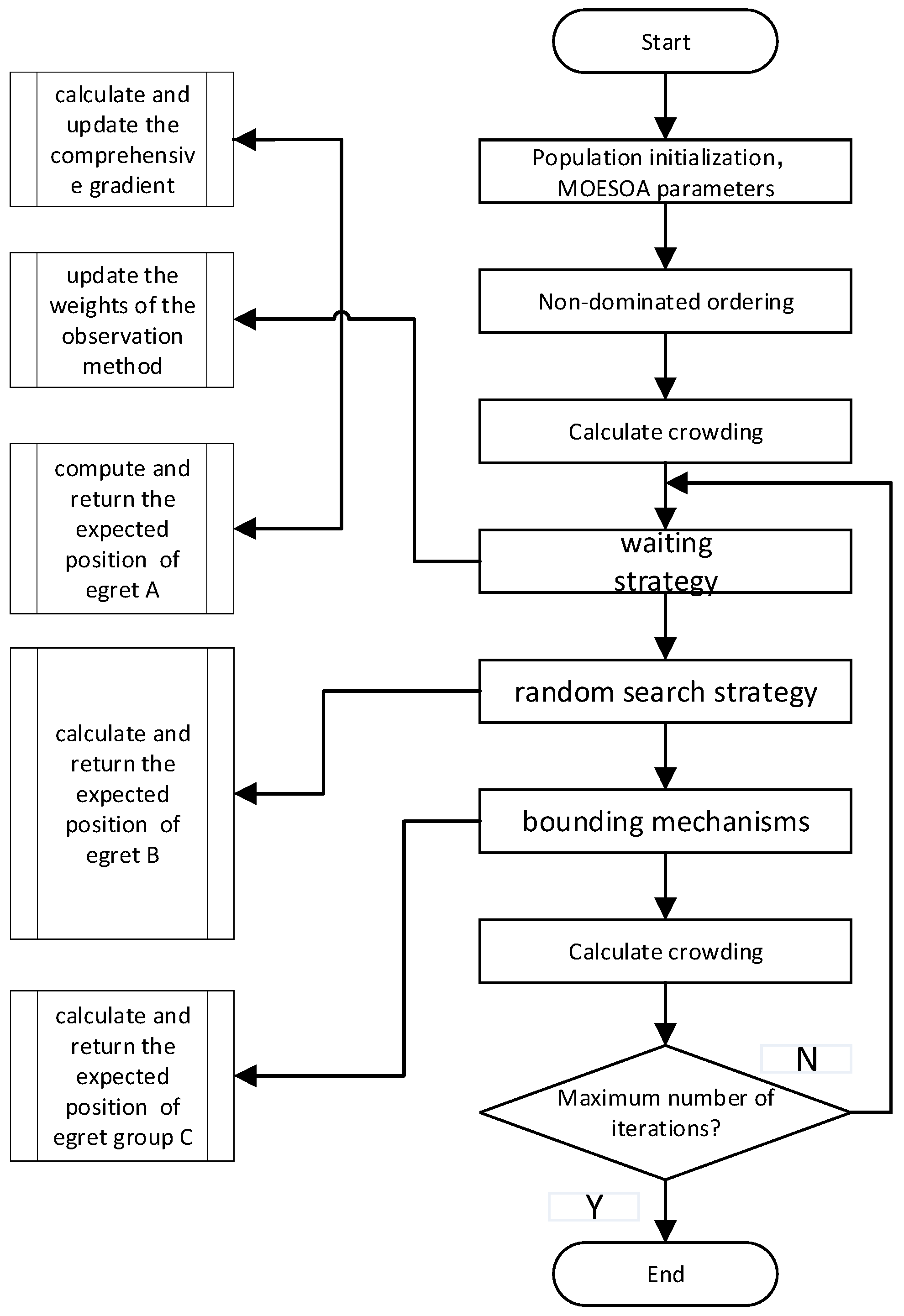
The ESA is a meta-heuristic algorithm proposed in 2022 [34,35,36], which mainly simulates the predatory behavior of egrets in nature and has low requirements regarding the tuning parameters [37]. In this study, non-dominated ranking is used to improve the egret algorithm such that it accepts a multi-objective optimization function, where the size of the non-dominated solution set is limited based on sample crowding in the optimization process. The specific process is summarized in Figure 2.
In this study, the cutting parameters are taken as optimization variables, carbon emission efficiency and processing time are taken as optimization objectives, and the improved egret algorithm is used for multi-objective optimization. The specific steps are as follows:
(1)
Population initialization: The initial population is randomly generated, where each individual in the population represents an egret squad. The position of the squad represents a combination of cutting parameters, and the fitness of the squad is calculated using the machining result prediction model. The population size is set to N and the maximum iterations to maxGen, where N is in [20, 200] and maxGen is in [100, 5000]. The optimization objectives are set to minimize the energy consumption E, manufacturing cost C, and product quality degradation.
(2)
Screening outstanding individuals: According to the fitness values of individuals in the initial population, non-dominated sorting is performed, and a non-dominated solution set with rank 1 is generated. Then, the crowding degree of the sample is calculated using the following formula:
I i = j = 1 n | f i ( i + 1 ) f i ( i 1 ) | f j max f j min
where I i is the crowding degree of the ith egret squad; n is the total number of optimization objectives; f j ( i + 1 ) ,   f j ( i 1 ) are the fitness value of egret squads i + 1 and i − 1 for optimization target j , respectively; and f j m a x and f j m i n are the maximum and minimum fitness values for optimization target j , respectively.
(3)
Calculate the expected position: Each egret squad consists of three egrets. Egret A adopts the forward guidance strategy, egret B adopts the random walk strategy, and egret C adopts the encircle strategy; in particular, each egret is defined according to the following equations:
x A = x i + exp ( k / ( 0.1 k max ) ) 0.1 h g i x B = x i + tan r b , i h / ( 1 + k ) x C = ( 1 r h r g ) x i + r h ( x i b e s t x i ) + r g ( x g b e s t x i )
where x A , x B , and x C are the expected positions of each egret; x i is the current position of the squad x A , i , x B , i , and x C , i ; k m a x is the maximum number of iterations; h is the scope of the current search space; g i is the gradient; r b , i is a random number in (−π/2,π/2); k is the number of current iterations; r h and r g are random numbers in [0,0.5); x i b e s t is the best position of the current egret squad; and x g b e s t is the best position of all egret squads (randomly selected from the non-dominated solution set).
(4)
Decision making: Calculate the fitness of each egret in its expected position, select the non-dominated solution according to the fitness values, and the egret team moves to the corresponding position. Then, the non-dominated solution is added to the Pareto solution set and redundant solutions in the Pareto solution set are eliminated according to the crowding ranking result. The best positions are compared before the egret team moves to the current position of the egret team, and the non-dominated solution of the two is set as the best position after the egret team moves.
(5)
Iteration: Iterate the above process repeatedly until the maximum number of iterations is reached.

5. Case Study

5.1. Problem Background

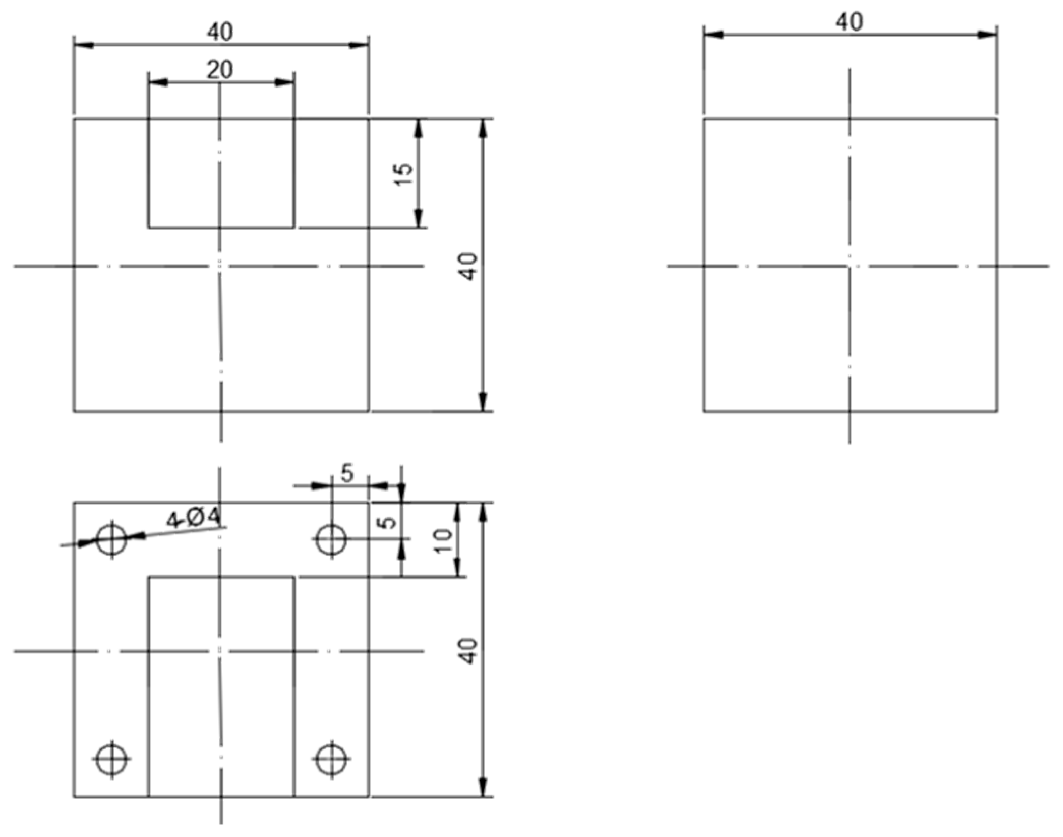
We consider the following problem: a factory needs to process a fixture cavity, the dimensions of which are shown in Figure 3. The workpiece material is 45 steel.
There are two milling machines in the workshop, and their parameters are presented in the following tables (Table 1 and Table 2).
The milling cutter selected for optimization was the YT15 carbide milling cutter, and the tool’s parameters are shown in Table 3. The tool radius was determined according to the characteristics of the part and, so, the selected tool diameter was 125 mm. The initial milling parameters were set based on experience. During processing, the spindle speed was selected as 400 (r/min), the feed rate was 0.2 (mm/r), and the milling depth was 2 mm. The milling width was 70 mm, and the required surface roughness was set as Ra = 6.4 µm. After the milling parameters were set, the processing experiment was performed.
According to reference [32], when the tool material is a hard alloy, its coefficients are given as: k F C = 0.25, C F = 7900, x F = 1.0, y F = 0.75, u F = 1.1, w r = 0.2, and q r = 1.3 ( k F C is the correction coefficient; C F is the cutting force coefficient; x F , y F , u F , w r , and q r are the influence indices of the relevant parameters, which can be obtained by referring to the relevant manuals). Other parameters included the minimum no-load power of the machine tool (=0.52/kw) and the spindle speed coefficients m 1 = 0.1, m 2 = 2.1 × 10⁻⁶. The data obtained for each item were substituted into the corresponding formulas for calculation, and it was concluded that the carbon emissions generated by processing this plane were 832.9 g, shown as Term 1 in Table 4.

5.2. Optimization Results

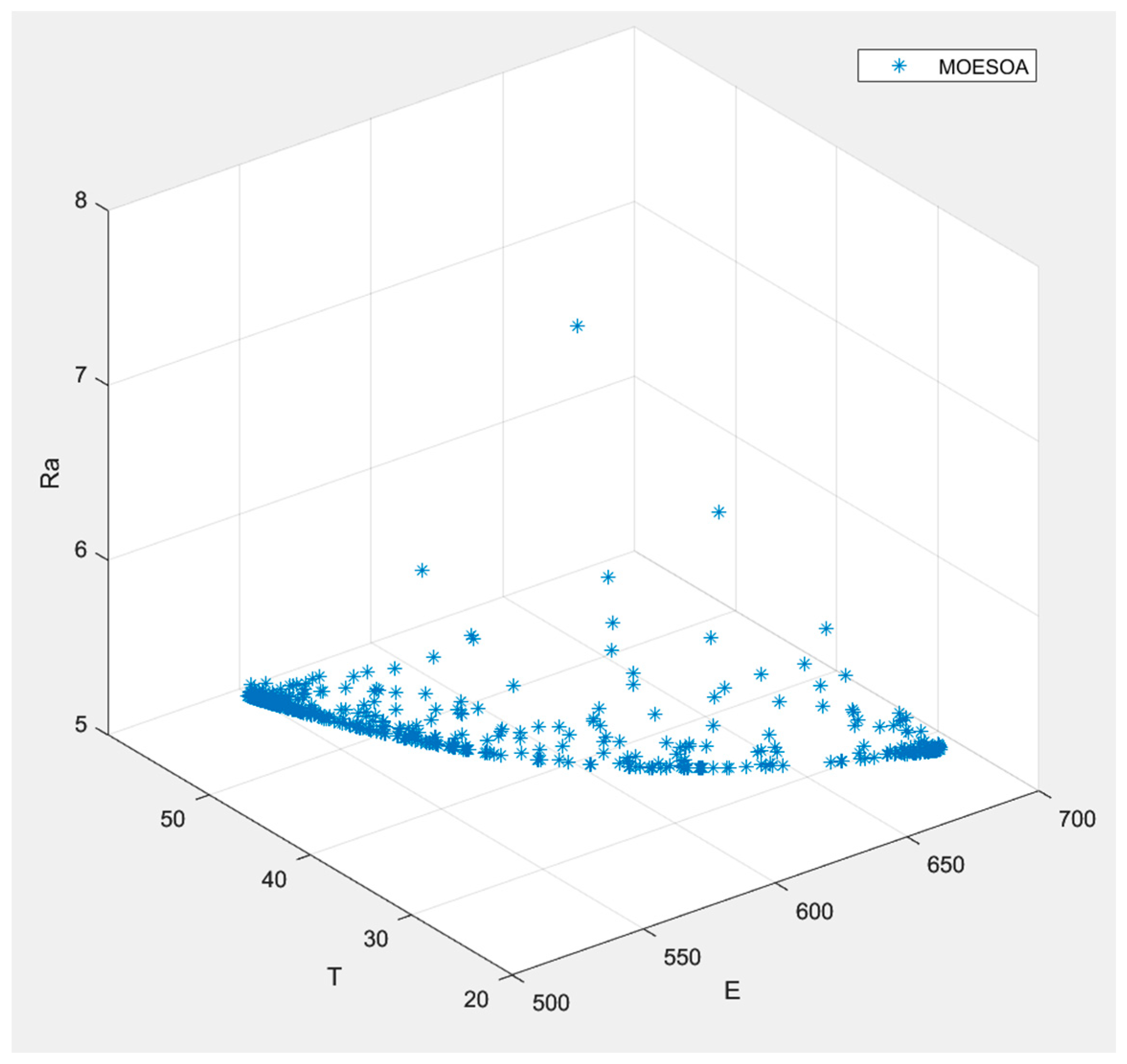
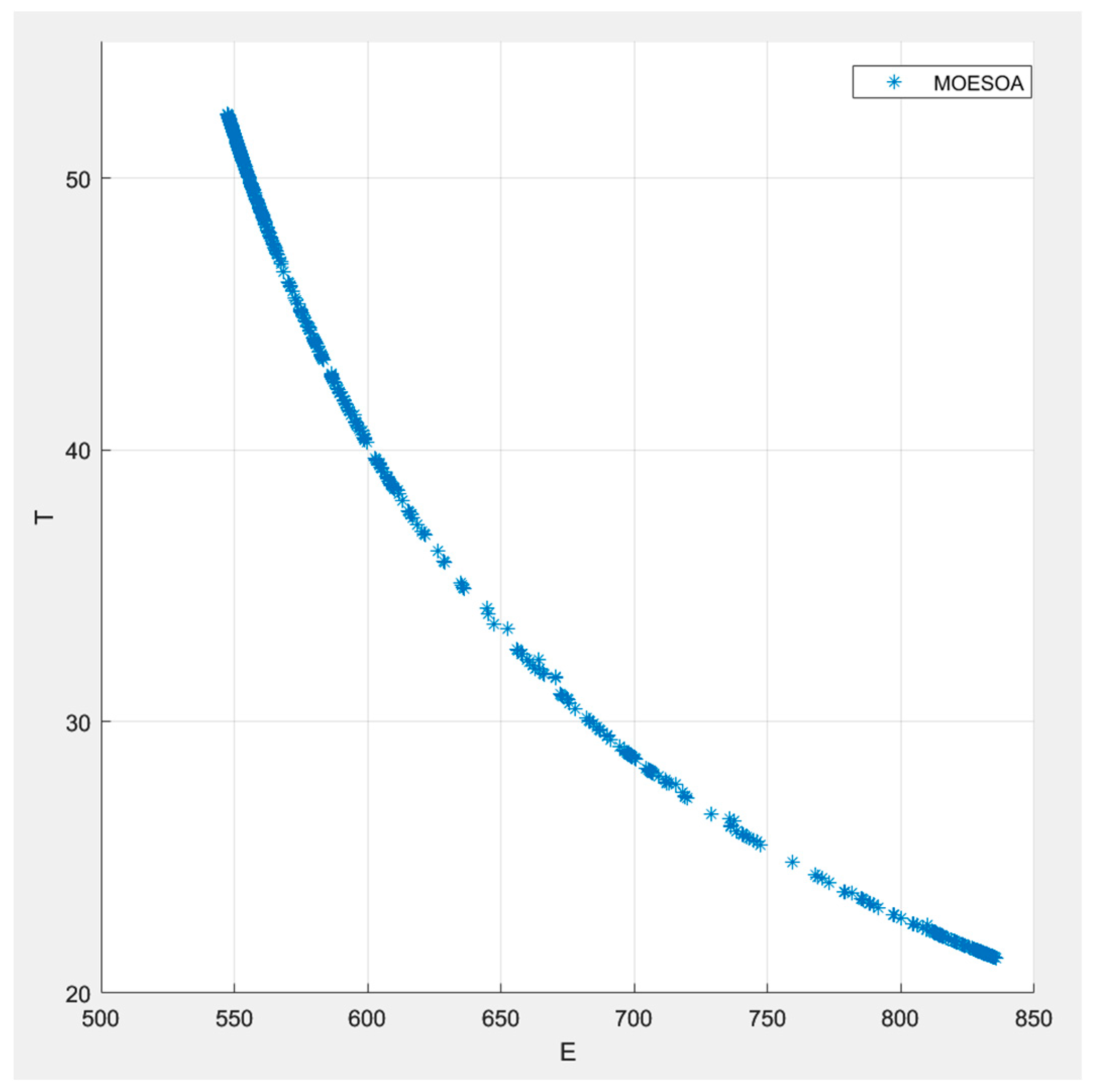
Using the egret swarm optimization algorithm, the optimal carbon emissions and processing time of different equipment types during processing of the same product were obtained. Figure 4 shows the Pareto frontiers for carbon emissions, processing time, and surface roughness of milling machine 2. Figure 5, Figure 6 and Figure 7 show the pairwise Pareto frontiers between carbon emissions, processing time, and surface roughness for milling machine 2. Term 2 in Table 4 shows the cutting parameters, carbon emissions, energy consumption, and so on for milling machine 2 when processing the same workpiece. Compared with milling machine 1, after optimization using the ESA, the processing time of milling machine 2 was 23.7 s, 5.6% lower than that of milling machine 1; the surface roughness was 5.4, 12.9% lower than that of M1; and the carbon emissions were 723.38 g, 13.1% lower than that of M1. Therefore, in the context of workshop production, the use of M2 can save more time while reducing carbon emissions. To further verify the effectiveness of this algorithm, we used the beetle antennae search (BSA) algorithm for comparison [38]. The verification results are shown in Figure 4. The results prove that BAS is also an effective algorithm; however, although it generally achieved better results than the baseline, the ESA algorithm had superior performance.
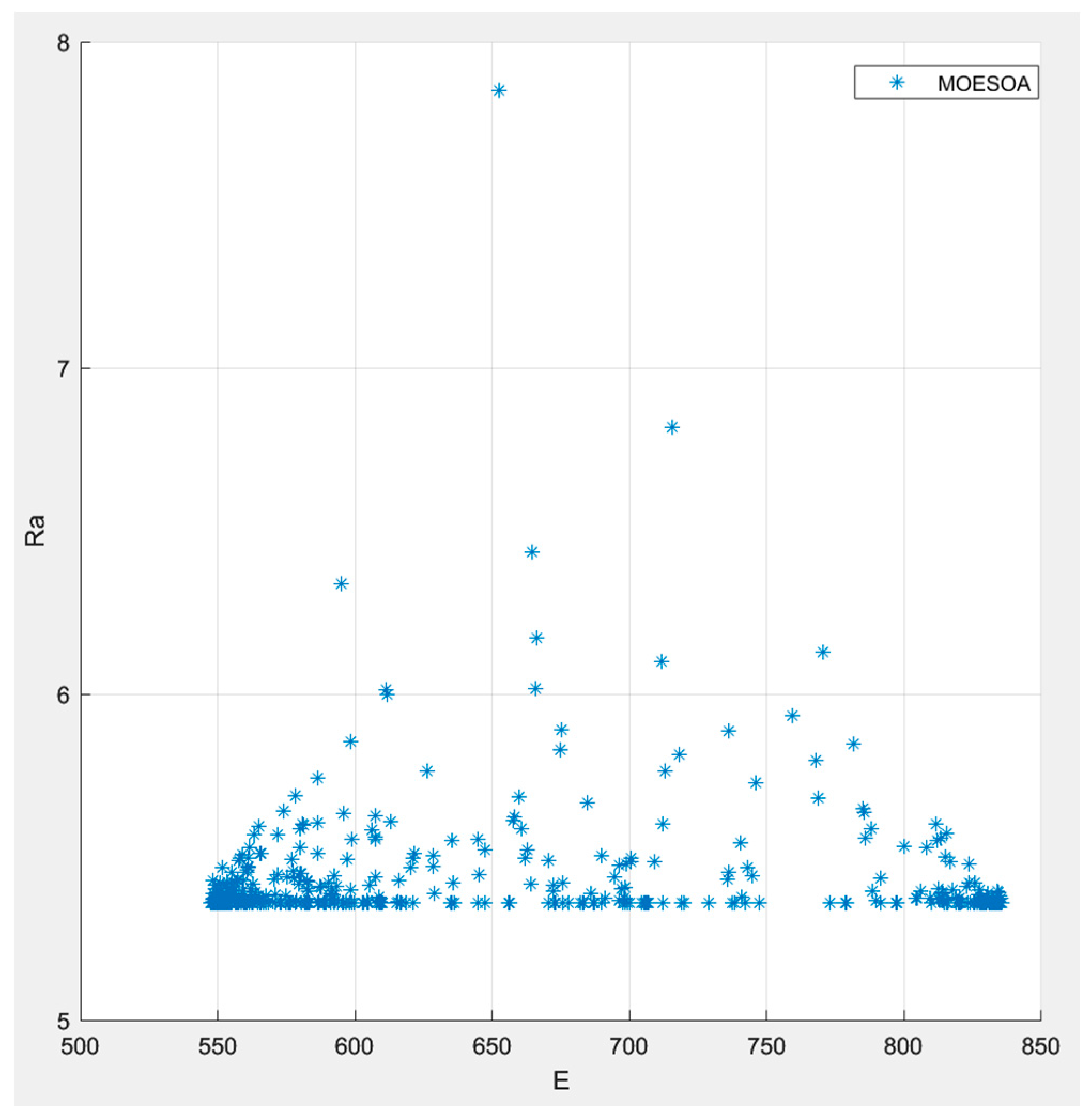
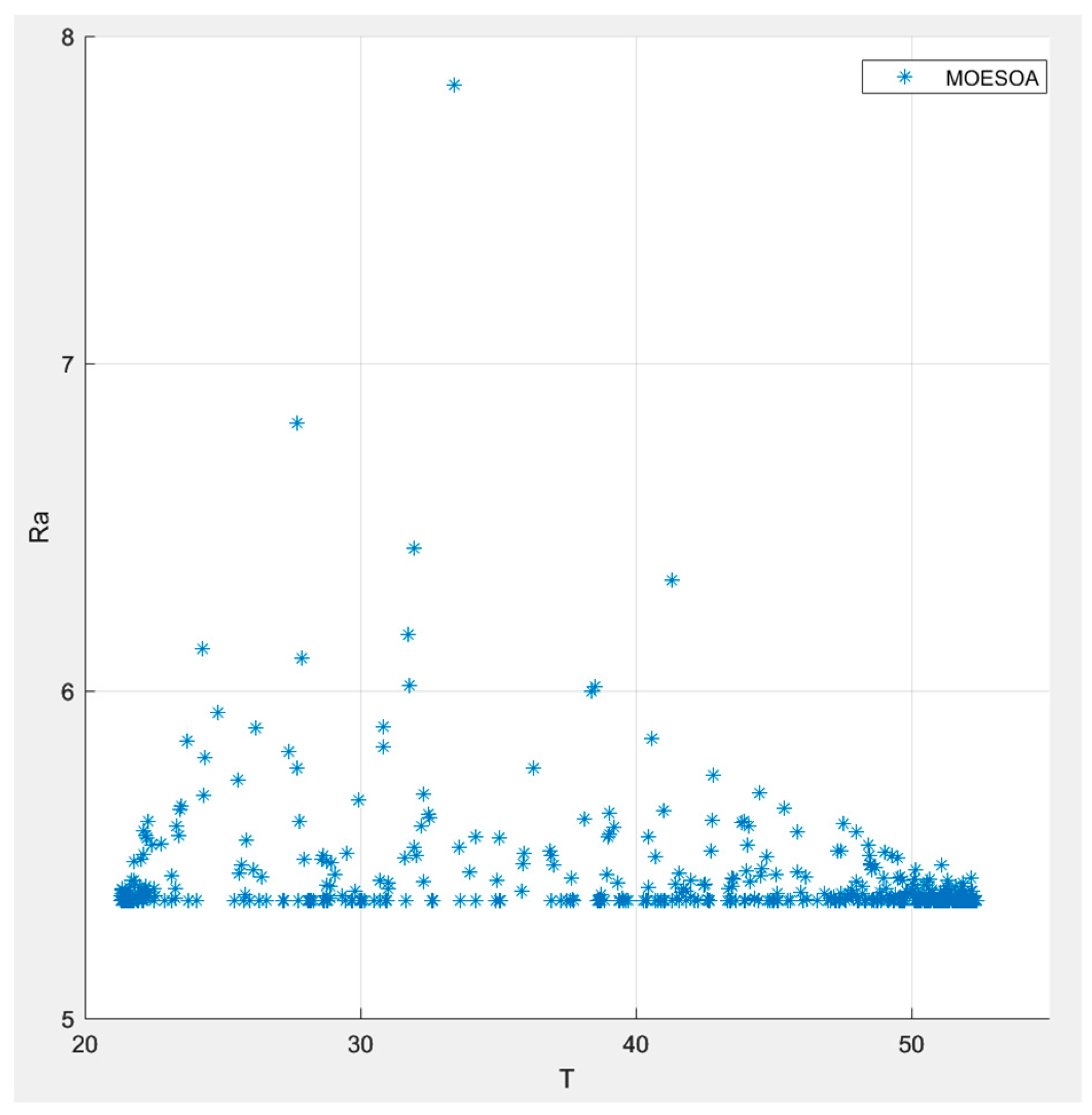
It can be further seen from Figure 5, Figure 6 and Figure 7 that the shorter the processing time requirement of the milling machine, the higher the energy consumption. Furthermore, under certain surface roughness requirements, an increase in processing time or carbon emissions has a limited optimization effect.

5.3. Practical Implications

Traditional equipment selection methods involve qualitative analysis mainly relying on evaluation indicators, which leads to an undeniable deviation between theoretical and actual data, and the reliability of the data may also be lacking. Therefore, this study constructed a set of efficient and low-carbon production equipment selection models, which can accurately calculate the processing time, carbon emissions, and surface roughness generated through the workshop process. To determine the optimal equipment solution, this study introduced the ESA, an algorithm characterized by excellent search ability, fast convergence speed, and a simple implementation process. It effectively overcomes the limitations of traditional methods and helps to optimize and upgrade workshop production processes towards high efficiency and reduced emissions.

6. Conclusions

The selection of production equipment is an extremely complex task that not only affects the production management of enterprises but is also of great significance for the sustainable development of society. Based on the NQP concept, this study constructed a workshop production equipment selection model and put forward a calculation method for equipment carbon emissions and processing time in the context of milling processes. This model allows for the comprehensive consideration of carbon emissions and process time when using different milling equipment to produce the same product, helping enterprises to achieve low-carbon and efficient production. The specific results are as follows:
  • Based on the NQP concept, a model for enterprise milling equipment selection was created, and the realization path of enterprise management was analyzed through the integration of enterprise management and equipment selection.
  • A calculation model for the carbon emissions and processing time for the same product produced with different milling equipment was established and verified through an example involving the machining of a fixture cavity.
  • The ESA was used to optimize the energy consumption and processing time of a multi-equipment process.
The results showed that this method allows for the analysis and evaluation of the processing time and carbon emissions of the same product when produced by different milling equipment, thus providing a reference for equipment selection by enterprises. However, this study still has certain limitations, as it only focused on the relationship between the part processing time and carbon emissions. Our future research will include more decision-making indicators, such as economic dimensions and energy consumption, and we will attempt to use different optimization algorithms to improve the results. Furthermore, there are several aspects that merit further in-depth exploration in future research. First, the scope of equipment selection could be expanded, specifically through quantifying NQP indicators and providing substantive guidance based on NQP for the machining industry to cover a broader range of industry usage scenarios. Second, further research should focus on dynamic modeling aspects such as dynamic equipment state change processing, dynamic monitoring of tool wear, and dynamic parameter adjustment to adapt to more complex manufacturing environments.

Author Contributions

Conceptualization, W.Q. and Z.N.; methodology, W.Q.; software, W.Q.; validation, Z.N.; formal analysis, Z.N.; investigation, W.Q.; data curation, W.Q.; writing—original draft preparation, W.Q.; writing—review and editing, Z.N. All authors have read and agreed to the published version of the manuscript.

Funding

This research received no external funding.

Data Availability Statement

The original contributions presented in this study are included in the article. Further inquiries can be directed to the corresponding author.

Conflicts of Interest

The authors declare no conflicts of interest.

Abbreviations

NPQNew Quality Productivity
ESAEgret Swarm Algorithm
GAGenetic Algorithm
SAASimulated Annealing Algorithm
DSADistributed Search Algorithm
CNCComputer Numerical Control
NSGA-IINon-dominated Sorting Genetic Algorithm II
MEOAMulti-objective Optimization Algorithms
PSOParticle Swarm Optimization
MECMinimum Energy Consumption
maxGenMax Generation

References

  1. Luo, W.; Zuo, S.; Tang, S.; Li, C. The Formation of New Quality Productivity of Agriculture Under the Perspectives of Digitalization and Innovation: A Dynamic Qualitative Comparative Analysis Based on the “Technology-Organization-Environment” Framework. Sustainability 2025, 17, 597. [Google Scholar] [CrossRef]
  2. Chen, F. Can New Quality Productivity Promote the Carbon Emission Performance—Empirical Evidence from China. Sustainability 2025, 17, 567. [Google Scholar] [CrossRef]
  3. Yuan, Y.; Zhang, Y.; Fu, G.; Li, J.; Luo, F. New quality productivity in the new era enabling scientific instruments “domestic substitution”. Exp. Technol. Manag. 2024, 41, 1–6. [Google Scholar] [CrossRef]
  4. Yao, H.; Wu, J. An Analysis of Innovative Contributions to the Important Discourse on the Development of New Quality Productivity. J. Contemp. Educ. Res. 2024, 8, 135–141. [Google Scholar] [CrossRef]
  5. Liu, Z. Sustainable Evolution of China’s Provincial New Quality Productivity Based on Three Dimensions of Multi-Period Development and Combination Weights. Sustainability 2024, 16, 11259. [Google Scholar] [CrossRef]
  6. Niroomand, S. Hybrid artificial electric field algorithm for assembly line balancing problem with equipment model selection possibility. Knowl. Based Syst. 2021, 219, 106905. [Google Scholar] [CrossRef]
  7. Sahin, Y.; Aydemir, E. A Comprehensive Solution Approach for CNC Machine Tool Selection Problem. Informatica 2021, 33, 81–108. [Google Scholar] [CrossRef]
  8. Yu, D.; Zhang, Y.; Luo, S.; Zou, W.; Liu, J.; Ran, Z.; Liu, W. A Data-Driven Strategy Assisted by Effective Parameter Optimization for Cable Fault Diagnosis in the Secondary Circuit of a Substation. Processes 2025, 13, 2407. [Google Scholar] [CrossRef]
  9. Zheng, Y.-H.; Hu, F.-H.; Wang, M.-H.; Wang, X.-Y. Research on the machine tool selection optimization method based on fuzzy analytic hierarchy process and fuzzy comprehensive assessment. Chin. J. Eng. Des. 2015, 22, 405–411. [Google Scholar] [CrossRef]
  10. Wang, Y.; Wang, Y.-C.; Niu, Y.; Zhao, J.-P. Optimization Selection of CNC Machine Tool Equipment Based on FAHP. Modul. Mach. Tool Autom. Manuf. Tech. 2014, 334, 133–136. [Google Scholar] [CrossRef]
  11. Zheng, Y.; Han, F.; Ma, Y. The Application of improved Gray Associated Models in Equipment Selection. Mach. Tool Hydraul. 2009, 37, 41–43. [Google Scholar] [CrossRef]
  12. Yan, Q.; Zhang, H.; Zhang, R.; Liu, H.; Zhang, G. Research on Optimization Evaluation of Machine Tool Equipment for Intelligent Manufacturing. Comb. Mach. Tool Autom. Process. Technol. 2020, 144–148. [Google Scholar] [CrossRef]
  13. Önüt, S.; Soner Kara, S.; Efendigil, T. A hybrid fuzzy MCDM approach to machine tool selection. J. Intell. Manuf. 2008, 19, 443–453. [Google Scholar] [CrossRef]
  14. Zhao, X.; Shen, M.; Wang, J. Machining process evaluation model based on low carbon manufacturing and application. J. Mech. Des. Manuf. 2013, 81–83. [Google Scholar] [CrossRef]
  15. Klink, A.; Arntz, K.; Johannsen, L.; Holsten, M.; Chrubasik, L.; Winands, K.; Wollbrink, M.; Bletek, T.; Gerretz, V.; Bergs, T. Technology-based assessment of subtractive machining processes for mold manufacture. Procedia CIRP 2018, 71, 401–406. [Google Scholar] [CrossRef]
  16. Vafadar, A.; Hayward, K.; Tolouei-Rad, M. Drilling reconfigurable machine tool selection and process parameters optimization as a function of product demand. J. Manuf. Syst. 2017, 45, 58–69. [Google Scholar] [CrossRef]
  17. Li, H.; Wang, W.; Fan, L.; Li, Q.; Chen, X. A novel hybrid MCDM model for machine tool selection using fuzzy DEMATEL, entropy weighting and later defuzzification VIKOR. Appl. Soft Comput. 2020, 91, 106207. [Google Scholar] [CrossRef]
  18. Zanuto, R.D.S.; Hassui, A.; Lima, F.; Dornfeld, D.A. Environmental impacts-based milling process planning using a life cycle assessment tool. J. Clean. Prod. 2019, 206, 349–355. [Google Scholar] [CrossRef]
  19. Zhang, B.-P.; Guan, S.-X.; Zhang, B.; Wang, B.; Tian, T. Machine tool selection based on fuzzy evaluation and optimization of cutting parameters. J. Meas. Sci. Instrum. 2015, 6, 384. [Google Scholar]
  20. Wang, L.P.; Kong, X.Y.; Yu, G. Motor servo control parameter tuning for parallel and hybrid machine tools based on a genetic algorithm. J. Tsinghua Univ. Sci. Technol. 2021, 61, 1106–1114. [Google Scholar]
  21. Sel, A.; Gurkan, M.E.; Hamzaday, A. Energy-aware production lot-sizing and parallel machine scheduling with the product-specific machining tools and power requirements. Comput. Ind. Eng. 2024, 196, 110503. [Google Scholar] [CrossRef]
  22. Chen, M.C. Optimization machining economics models of turning operations using the scatter search approach. Int. J. Prod. Res. 2004, 42, 2611–2625. [Google Scholar] [CrossRef]
  23. Gontarz, S.; Patyk, R.; Bohdal, L.; Jackiewicz, D. Multiparameter optimization of mechanical cutting process of grain-oriented silicon steel. Acta Phys. Pol. A 2020, 137, 930–932. [Google Scholar] [CrossRef]
  24. Wang, X.; Gu, X.; Liu, Z.; Wang, Q.; Xu, X.; Zheng, M. Production Process Optimization of Metal Mines Considering Economic Benefit and Resource Efficiency Using an NSGA-II Model. Processes 2018, 6, 228. [Google Scholar] [CrossRef]
  25. Wang, Y.; Guo, L. Research on the impact of digital innovation and entrepreneurship on the development of new quality productivity. Econ. Issues Explor. 2025, 46, 37–49. Available online: http://www.jjwtts.com/CN/Y2025/V46/I1/37 (accessed on 1 January 2025).
  26. Wang, J.; Qiao, L.; Zhu, G.; Di, K.; Zhang, X. Research on the driving factors and impact mechanisms of green new quality productive forces in high-tech retail enterprises under China’s Dual Carbon Goals. J. Retail. Consum. Serv. 2025, 82, 104092. [Google Scholar] [CrossRef]
  27. Wu, F.-P.; Song, Y.; Huang, R. Construction of new quality productivity evaluation index system under new development concept. Water Resour. Prot. 2019, 41, 85–91. [Google Scholar]
  28. Sun, Y.B.; Ye, J.N.; Hu, J. Optimization of Mechanical processing Technology and Application of digital Twin technology. Chin. Mach. 2023, 27, 36–39. [Google Scholar]
  29. Liu, J.F.; Zhao, P.; Zhou, H.G.; Liu, X.-J.; Feng, F. The evaluation method of mechanical processing technology driven by digital twins. Comput. Integr. Manuf. Syst. 2019, 25, 1600–1610. [Google Scholar] [CrossRef]
  30. Song, Z.; Liu, D.; Sha, H.; Jiang, X.; Tian, Z.; Yang, G. Carbon emission warning method for machine tool manufacturing process based on dynamic adaptive EWMA control chart. Environ. Sci. Pollut. Res. 2024, 31, 53156–53176. [Google Scholar] [CrossRef]
  31. Hu, S.H.; Liu, F.; He, Y. Study on the characteristics of no-load energy parameters of variable frequency main drive system of CNC ma-chine tools. Comput. Integr. Manuf. Syst. 2012, 18, 326–331. [Google Scholar]
  32. Ai, X.; Xiao, S.G. Handbook of Cutting Usage Concise; Mechanical Industry Press: Beijing, China, 1994; p. 110. [Google Scholar]
  33. Huang, Z.T. Research on Modeling and Cutting Parameters Optimization of CNC Milling Process for Low Carbon Manufacturing. Master’s Thesis, Huazhong University of Science and Technology, Wuhan, China, 2016. [Google Scholar] [CrossRef]
  34. Ansho, P.M.; Nisha, M.G. Egret Swarm Optimized Distributed Power Flow Controller for Power Quality Enhancement in Grid Connected Hybrid System. J. Electr. Eng. Technol. 2024, 19, 2047–2057. [Google Scholar]
  35. Chen, Z.; Francis, A.; Li, S.; Liao, B.; Xiao, D.; Ha, T.T.; Li, J.; Ding, L.; Cao, X. Egret Swarm Optimization Algorithm: An Evolutionary Computation Approach for Model Free Optimization. Biomimetics 2022, 7, 144. [Google Scholar] [CrossRef] [PubMed]
  36. Alajlan, A.M.; Razaque, A. ESOA-HGRU: Egret swarm optimization algorithm-based hybrid gated recurrent unit for classification of diabetic retinopathy. Artif. Intell. Rev. 2023, 56, 1617. [Google Scholar] [CrossRef]
  37. Manivannan, K.; Sathiamoorthy, S. Automated Tuberculosis classification using Egret Swarm Optimization with deep learning based fusion model on chest X-ray images. J. Intell. Fuzzy Syst. Appl. Eng. Technol. 2023, 45, 10335–10347. [Google Scholar] [CrossRef]
  38. Xiao, Y.M.; Chen, G.H.; Zhang, H.; Zhu, X.Y. Optimization of Low-Carbon and Highly Efficient Turning Production Equipment Selection Based on Beetle Antennae Search Algorithm (BAS). Processes 2023, 11, 911. [Google Scholar] [CrossRef]
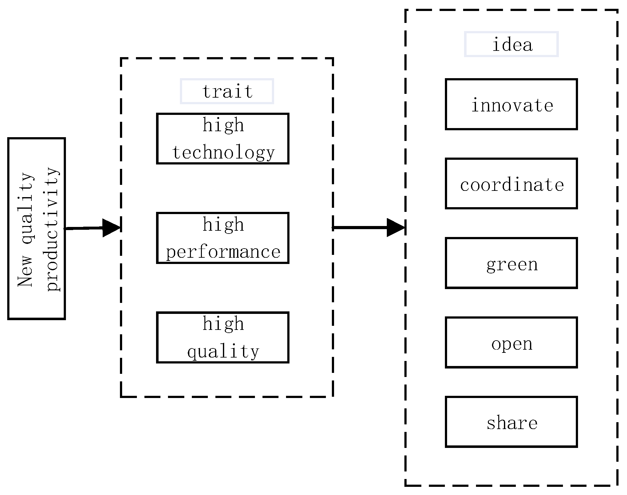
Figure 1. NQP framework.
Processes 13 02935 g001
Figure 2. Flowchart of ESA.
Processes 13 02935 g002
Figure 3. Workpiece size diagram.
Processes 13 02935 g003
Figure 4. M2 multi-objective optimization diagram.
Processes 13 02935 g004
Figure 5. Pairwise Pareto frontier between energy consumption and processing time for M2.
Processes 13 02935 g005
Figure 6. Pairwise Pareto frontier between energy consumption and surface roughness for M2.
Processes 13 02935 g006
Figure 7. Pairwise Pareto frontier between processing time and surface roughness for M2.
Processes 13 02935 g007
Table 1. Specifications of CNC milling machine 1.
n   ( r · m i n 1 ) P m a x   ( k W ) f z   ( m m · r 1 ) η K m M m a x   ( N · m )
50–350020.02–50.80.220
Table 2. Specifications of CNC milling machine 2.
n   ( r · m i n 1 ) P max   ( k W ) f z   ( m m · r 1 ) η K m M m a x   ( N · m )
100–60005.50.02–50.80.228.5
Table 3. Tool parameters.
Tool TypeTool Diameter (mm)Tool TeethTip Radius rε (/mm)
YT15 carbide12543
Table 4. Raw cutting parameters.
Termn (r/min) f z   ( m m / r ) ap (mm) T a v e (s) R a   ( μ m ) C e t (gco2e)
M14000.40225.16.2832.9
M2 (ESA)4240.40223.75.4723.38
M1 (BSA)4170.41224.65.4813.25
M2 (BSA)4190.41224.35.4739.6
Disclaimer/Publisher’s Note: The statements, opinions and data contained in all publications are solely those of the individual author(s) and contributor(s) and not of MDPI and/or the editor(s). MDPI and/or the editor(s) disclaim responsibility for any injury to people or property resulting from any ideas, methods, instructions or products referred to in the content.