Article

Towards Efficient Waste Handling: Structural Group Reduction in Lifting Mechanism Design

1
Department of Environmental Engineering, Mechanical Engineering and Agritourism, Faculty of Engineering, “Vasile Alecsandri” University of Bacau, 600115 Bacau, Romania
2
Engineering Faculty, University of Applied Sciences in Nowy Sacz, Zamenhofa 1a, 33-300 Nowy Sacz, Poland
3
Institute of Vehicles and Construction Machinery Engineering, Warsaw University of Technology, 02-524 Warsaw, Poland
4
Faculty of Mechanical Engineering and Mechatronics, University Politehnica of Bucharest, 060042 Bucharest, Romania
*
Authors to whom correspondence should be addressed.
Processes 2025, 13(9), 2744; https://doi.org/10.3390/pr13092744
Submission received: 5 August 2025 / Revised: 21 August 2025 / Accepted: 25 August 2025 / Published: 28 August 2025
(This article belongs to the Section Manufacturing Processes and Systems)

Abstract

This article presents a theoretical kinematic analysis of a mechanism for lifting and emptying household waste containers, critical components of garbage truck operations. The study focuses on optimizing waste handling mechanisms and highlights the impact of design parameters on performance. Using both classical analytical methods and modern simulation tools, including Mathcad 15 and Linkage v.3.16.14 software, the analysis identifies key influences of structural parameters on motion behavior. Unlike previous studies (which, for the mechanism under study, would use five structural groups), this work models the mechanism with fewer structural groups (three structural groups are used), simplifying analysis without sacrificing accuracy. Simulations confirm the validity of the calculations, showing no discrepancies in component movements and a maximum of 2.81% variation in linear velocities at all critical points. Detailed motion graphs illustrate the trajectories of mobile joints, with particular attention to angular variations and linear speeds, underscoring the importance of parameter optimization for enhanced performance.

1. Introduction

With the development of human society, populations began concentrating in specific areas, forming cities and urban agglomerations. Regardless of the activities carried out by urban residents, waste generation has been a constant feature. Over time, the volume of waste has increased, producing negative impacts on public health and the environment. This trend led to the establishment of the first urban sanitation services, whose primary objectives were the collection, transportation, and disposal of waste [1,2,3,4,5,6,7].
Initially, waste transport methods corresponded to the technological level of society at the time. However, as waste volumes grew, the need arose to transform and improve transportation means to handle increasingly larger quantities [8,9].
Parallel to the evolution of waste transport methods, the design of temporary waste storage containers also advanced. To optimize the loading process of household waste into garbage trucks, a series of mechanisms were introduced for lifting and emptying containers [10,11,12,13,14].
Today, garbage trucks are equipped with a variety of container loading systems [15,16,17,18], including:
  • Front-loading systems: used primarily for emptying large containers servicing commercial and industrial enterprises;
  • Rear-loading systems: featuring a rear chute for waste collection, where waste is deposited manually by an operator (e.g., garbage bags or bins) or mechanically using a lifting device capable of handling containers up to 1100 L;
  • Side-loading systems: similar to rear loaders, either manual or mechanized, where waste is loaded into the truck’s side-mounted storage hopper, typically accommodating containers up to 240 L.
For mechanized bin emptying, regardless of container size, various handling systems are employed. These systems lift containers to a specific height and then rotate them to discharge their contents. The mechanisms generally consist of [15,19,20,21,22,23,24]:
  • Mechanical elements actuated by hydraulic systems;
  • Rotating shafts transmitting motion through transmission systems such as worm gears or chain drives, etc.
The specialized literature presents numerous research studies [5,25,26,27,28] analyzing the impact of design parameters on the kinematics of such mechanisms. These analyses are critical for engineers seeking to improve the performance, efficiency, and reliability of waste-handling systems. Key design factors, such as the size, shape, material, and positioning of components, directly affect functional parameters like speed and acceleration. For instance, modifying the dimensions of a mechanism’s elements can either enhance or degrade its performance. Thus, understanding these influences is crucial for mechanism optimization.
A thorough grasp of the role of kinematic parameters aids in designing new mechanisms that are more efficient, durable, and reliable, ultimately contributing to the advancement of industrial equipment. By optimizing design parameters, engineers can develop innovative systems with superior performance and extended service life.
Typically, the structural analysis of mechanisms is conducted using various methods, including kinematic models [29,30,31,32,33], calculation algorithms [34,35,36], mathematical synthesis [37], and mathematical models [38,39,40]. Depending on the reference frame, analysis can be performed in either two-dimensional (2D) [41,42,43,44] or three-dimensional (3D) systems [45,46]. These approaches provide a detailed understanding of mechanism function and support optimization efforts for a range of industrial applications. Additionally, the literature reports extensive use of finite element analysis (FEA) to investigate the mechanical behavior and stress distribution in various types of mechanisms [23,24,47,48,49,50,51,52].
It is mentioned that the primary aim of the article is not to identify a new lifting system for a load (garbage bin). Instead, it adopts an existing mechanism from specialized literature and practical systems, aiming to develop a new method of structural calculation for it, more specifically, to reduce the number of structural groups, which is not addressed in the specialized literature. This reduction in structural groups leads to the formulation of general equations, which can be applied to this type of mechanism, provided that the values of the dimensional elements permit its kinematic motion. Can the reduction in the number of structural groups be justified by the advantages it brings in terms of simplifying kinematic modelling? We will try to answer this question below.
The purpose of this article is to enrich the specialized literature with studies on complex mechanisms used in various fields of activity. To achieve this, a theoretical analysis was conducted to identify new forms of calculation relationships (complex forms) that describe the movements of the components of the studied mechanism. It is mentioned that the analysis performed is a structural analysis of the mechanism, specifically an analysis of its kinematics. As a result of this approach, the aim is to obtain calculation relationships that are not found in the specialized literature.

2. Materials and Methodology

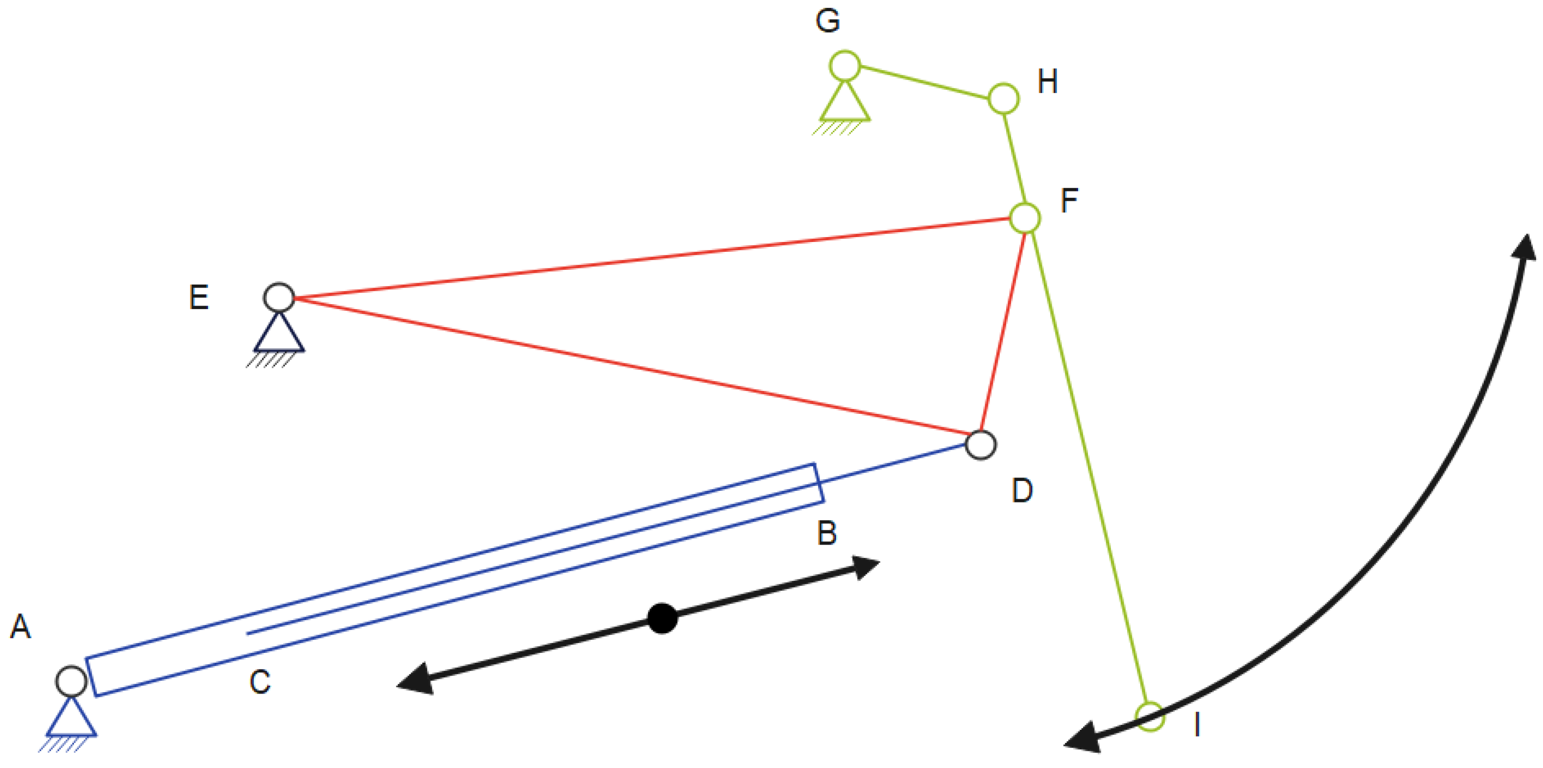
In this article, a mechanism used for lifting and lowering a container to empty its contents (Figure 1) will be subjected to theoretical analysis. Such mechanisms are commonly found as a main component in numerous garbage trucks. The selection of this mechanism can be justified by its availability and accessibility in the local context, as the waste collection vehicles in the municipality (Bacau, Romania) are already equipped with this type of mechanism.
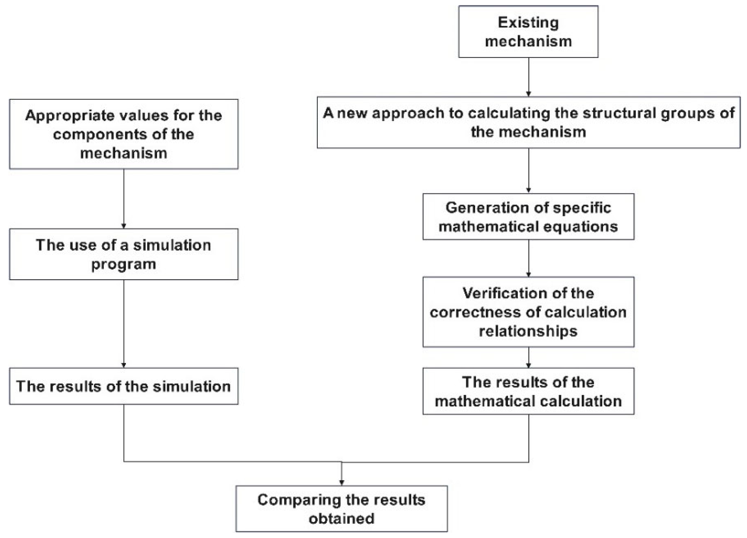
This type of mechanism performs the operation of emptying the container using a piston as the actuating element, which drives a series of components of the mechanism. Depending on its position (maximum stroke or minimum stroke), it executes the lifting or lowering movement of the load. The article uses the method of analyzing a mechanism, namely dividing it into structural groups.
The working methodology presented in Figure 2 will be used for this purpose.
To verify the accuracy of the obtained calculation relationships, a specialized program for structural analysis of a mechanism, namely Linkage v.3.16.14, was used. Therefore, a comparison of the results obtained was made to identify the differences between the two methods.

3. Theoretical Considerations

To analyze the mechanism geometrically, it was divided into several parts, which will be individually analyzed. Figure 3 presents the groups of elements that will be studied further. In the specialized literature, to determine the movement of components, such a mechanism would be decomposed into a series of structural groups (simple geometric forms used for calculations) [37,40,41,42,43]. Referring strictly to this mechanism, it would be divided as follows (according to this method):
  • Group 1—consists of the hydraulic piston AD (binary elements with a sliding element);
  • Group 2—consists of the elements ADE (binary elements);
  • Group 3—consists of the elements DEF (ternary element);
  • Group 4—consists of the elements GHF (binary elements);
  • Group 5—consists of the elements HFI (binary elements).
These groups are created to determine, step by step, the movement of each component of the mechanism, respectively:
  • Group 1—used to determine the value of the distance between joints A and D;
  • Group 2—used to determine the value of the coordinates of joint D and the value of the angle formed by element ED with the horizontal;
  • Group 3—used to determine the value of the coordinates of joint F and the value of the angle formed by element EF with the horizontal;
  • Group 4—used to determine the value of the coordinates of joint H and the value of the angle formed by element HF with the horizontal;
  • Group 5—used to determine the value of the coordinates of joint I.
As previously mentioned, the mechanism will be subjected to an analysis with the ultimate goal of obtaining design equations for it, particularly equations that have a general usage character (i.e., not obtained for specific construction cases). Therefore, the structural element groups used in this article for the geometric analysis of the mechanism are presented below:
  • Group 1—consists of the hydraulic piston AD (binary elements with a sliding element);
  • Group 2—consists of the elements ADEF (binary element with ternary element);
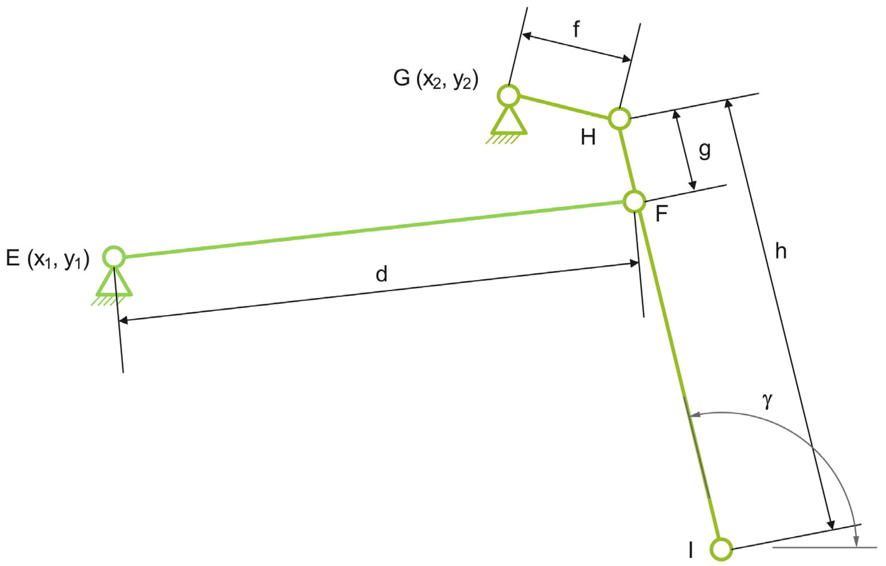
  • Group 3—consists of the elements EFGHI (quadrilateral mechanism).
The mechanism presented in Figure 3 operates by transforming the linear motion generated by the hydraulic piston into a complex combination of translational and rotational motion, used for lifting and emptying waste containers. The actuation begins with the extension of the piston, which displaces point D and alters the length of element AD. This motion is transmitted to elements DE and FE through a structural group composed of binary and ternary elements (ADEF), resulting in the movement of the mobile joint F. Subsequently, the motion propagates to the group EFGHI, which forms a four-bar mechanism extended toward the mobile joint I, generating an amplified and complex trajectory of this joint. Thus, the linear motion produced by the extension of the hydraulic piston is transformed into a curvilinear displacement of the mobile joint I, enabling the lifting, rotation, and emptying of the container, followed by its return to the initial position. The entire process unfolds symmetrically and cyclically, and the trajectories of the mobile points (D, F, H, I) are influenced by the geometry and positioning of the component elements.
To identify the mathematical calculation relationships corresponding to the studied mechanism, the movement performed by each previously presented group of elements was analyzed as follows:
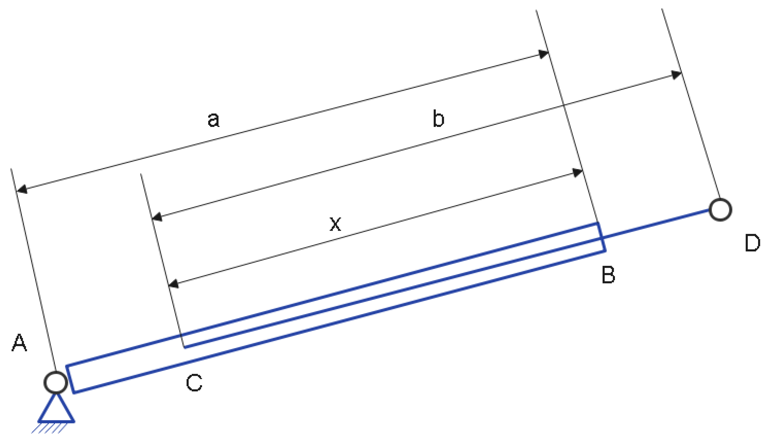
  • Group 1—Figure 4 presents the dimensional elements of the components that make up this group. Specifically, this figure represents the element generating linear motion (namely the piston with its two components: the cylindrical element with dimension a and the piston with dimension b. Since the two components presented earlier (the cylinder and the piston) interpenetrate, this overlap of components is characterized by the dimensional value c.
The variation in the distance between the free end of the piston, point D, and the fixed element, point A, can be determined using the calculation relationship:
l 1 =   a + b x
  • To determine the movement of points D and F of the mechanism, it is necessary to analyze the movements performed by the group consisting of binary and ternary elements presented in Figure 5. Within this group of components, the coordinates of points A and E are known, and the distances between points E and D, E and F, and D and F are fixed. By analyzing the group of elements in Figure 5, a triangle ADE is identified, but since side AD (whose length l1 varies) changes, the shape of the triangle varies. In this case, the coordinates describing the movement of point D are given by Equations (2) and (3).
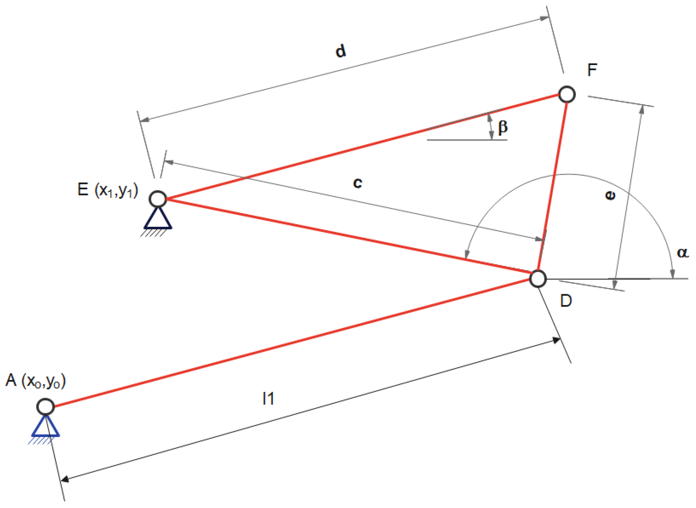
Figure 5. Group 2 of elements.
Processes 13 02744 g005
x D = x 0 + x 0 + x 1 · l 1 2 c 2 + d A E 2 2 · d A E 2 d 1 · y 0 y 1 2 · d A E 2
y D = y 0 ( x 0 + x 1 ) · d 1 2 · d A E 2 + ( l 1 2 c 2 + d A E 2 ) ( y 0 + y 1 ) 2 · d A E 2
In which the following notations were made:
d A E =   ( x 0 x 1 ) 2 + ( y 0 y 1 ) 2
d 1 = l 1 + c + d A E · l 1 + c d A E · l 1 + c + d A E · l 1 c + d A E
In addition to the coordinates of point D, it is important to determine the value of the angle described by line ED in relation to the horizontal axis. The value obtained for this angle is relative to a coordinate system where the origin is at point D (Equation (6)). Using Equations (2) and (3), this calculation relationship can also be written in the form presented in Equation (7).
α = 180 a r c t a n y 0 y 1 ( x 0 + x 1 ) · d 1 2 · d A E 2 + ( l 1 2 c 2 + d A E 2 ) ( y 0 + y 1 ) 2 · d A E 2 x 1 x 0 x 0 + x 1 · l 1 2 c 2 + d o 2 2 · d A E 2 + d 1 · y 0 y 1 2 · d A E 2
α = 180 a r c t a n y D y 1 x 1 x D
It is also mentioned that the ternary element ADE (Figure 4) is a rigid element with a fixed joint at point E. Considering this, as well as the entire structure under analysis, the coordinates generated by the movement of point F can be determined using the following calculation relationships:
x F =   x 1 + ( c 2 + d 2 e 2 ) · ( x D x 1 ) 2 · c 2 + d 2 · ( y 1 y D ) 2 · c 2
y F = y 1 + d 2 · ( x D x 1 ) 2 · c 2 + ( c 2 + d 2 e 2 ) · ( y D y 1 ) 2 · c 2
In which:
d 2 =   c + d + e · c + d e · c d + e · c + d + e
The angle described by element EF in relation to the horizontal (with the origin of the coordinate system positioned at point F):
β = 180 a r c t a n y F y 1 x 1 x F
Group 3 consists of elements EFGHI (Figure 6). Analyzing this group of elements, it is found that elements EFHG form a four-bar crank-rocker mechanism. It should be noted that IF is an extension of HF, meaning that mechanically we have an element HI with a joint at F. Considering the above, the following components will be determined.
The coordinates generated by the movement of point H:
x H = ( f 2 g 2 + d 3 2 ) ( d · c o s β + x 1 x 2 ) 2 d 3 2 + x 2 + d 4 · ( d · s i n β y 1 + y 2 ) 2 d 3 2
y H = ( d 3 2 + f 2 g 2 ) ( d · s i n β + y 1 y 2 ) 2 d 3 2 + d 4 · ( d · c o s β + x 1 x 2 ) 2 d 3 2 + y 2
The coordinates generated by the movement of point I:
x I = a a + h · x 1 a a + d · c o s β g
y I = b b h · b b y 1 + d · c o s β g
where:
a a =   x 1 + f 2 + g 2 + d 3 2 · x 2 x 1 + d · c o s β 2 · d 3 2 d 4 · y 1 y 2 + d · s i n β 2 · d 3 2 + d · c o s β
b b = y 1 d 4 · x 2 x 1 + d · c o s β 2 · d 3 2 + f 2 + g 2 + d 3 2 · y 2 y 1 + d · s i n β 2 · d 3 2 + d · s i n β
and:
d 3 = x 2 x 1 + d · c o s β 2 + y 2 y 1 + d · s i n β 2
d 4 = f + g + d 3 · f + g d 3 · f g + d 3 · f + g + d 3
The angle is described by element HI in relation to the horizontal (with the origin of the coordinate system positioned at point I):
γ = 360 a r c t a n y 1 + b b d · s i n β x 1 a a + d · c o s β
Attempts were made to obtain calculation relationships corresponding to the linear velocity parameter, but due to the complexity of the structural groups, this was not possible. Therefore, to analyze the variation of this parameter, the classical method of determination was chosen, and velocity was calculated using finite differences.

4. Results

To verify the calculation relationships presented earlier, the dimensional parameters of the mechanism are provided below. These values will be used to check the correctness of the previously presented mathematical values. Since it was not possible to identify the dimensions of a loading–unloading system for garbage bins with a volume of 1100 L (which would also require the agreement of the garbage truck manufacturer), the values for verification were chosen to ensure the proper functioning of the mechanism.
Similarly, by using values other than those found in actual garbage trucks, it was intended to highlight that the previously described relationships have a general character. These calculation relationships do not consider certain constructive restrictions, but only those related to functionality. Below are the values used (with measurements in cm) to verify the relationships described in the previous chapter:
  • Coordinates of fixed points:
    For the joint/point A—x0 = 0; y0 = 0;
    For the joint/point E—x1 = 15 cm; y1 = 52 cm;
    For the joint/point G—x2 = 62 cm; y2 = 71 cm;
  • Dimensional values of the elements:
    Element AB, denoted as a, has a value of 80 cm;
    Element CD, denoted as b, has a value of 70 cm;
    Element CB, denoted as x, has a value of 40 cm;
    Element DE, denoted as c, has a value of 86 cm;
    Element EF, denoted as d, has a value of 74 cm;
    Element FD, denoted as e, has a value of 45 cm;
    Element GH, denoted as f, has a value of 27 cm;
    Element HI, denoted as h, has a value of 98 cm;
    The distance between joint H and joint F, denoted as g, has a value of 22 cm.
To verify the calculation relationships, Mathcad 15 software was used [54]. The calculation was performed for 244 values distributed over a time interval of 8 s (an interval that includes the lifting and lowering action of the load). This interval was chosen to obtain the same number of values as those obtained using the Linkage v.3.16.14 simulation program [53]. In the mathematical calculation, the movement of the mechanism was studied by respecting the movements performed by it (in reality), namely:
  • The movement of lifting the container to unload household waste from it;
  • The movement of lowering the container to remove it from the lifting system.
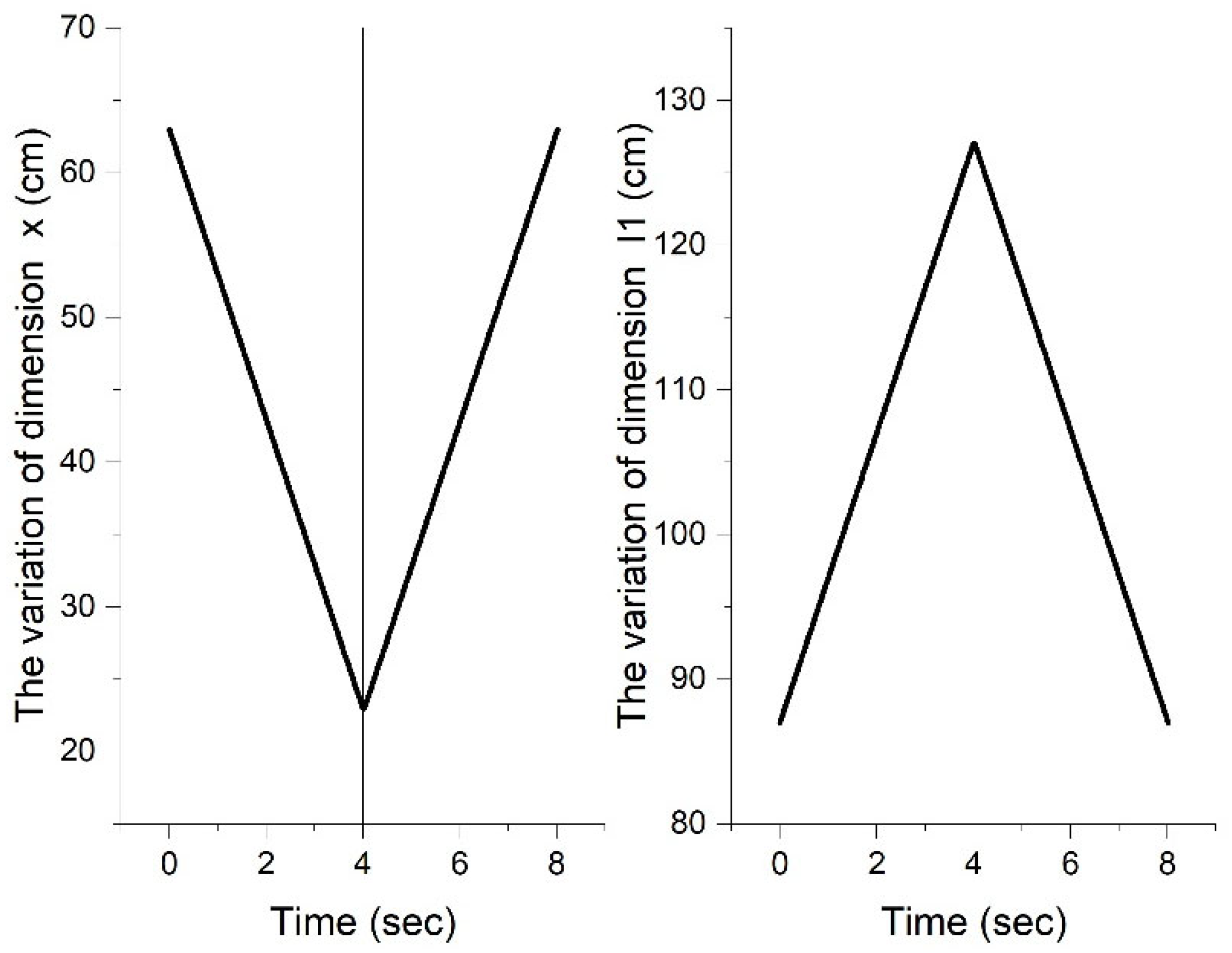
Since the component under study is nothing more than a hydraulic actuation system, the variations presented in Figure 7 indicate a symmetrical and periodic change within a specified time interval (4 s). It can also be observed that the dimensional variation of the studied parameter (element AD with length l1) is inversely proportional to the variation of element BC (with length x). Both graphs show periodic variations in dimensions x and l1, suggesting a mechanism that operates cyclically.
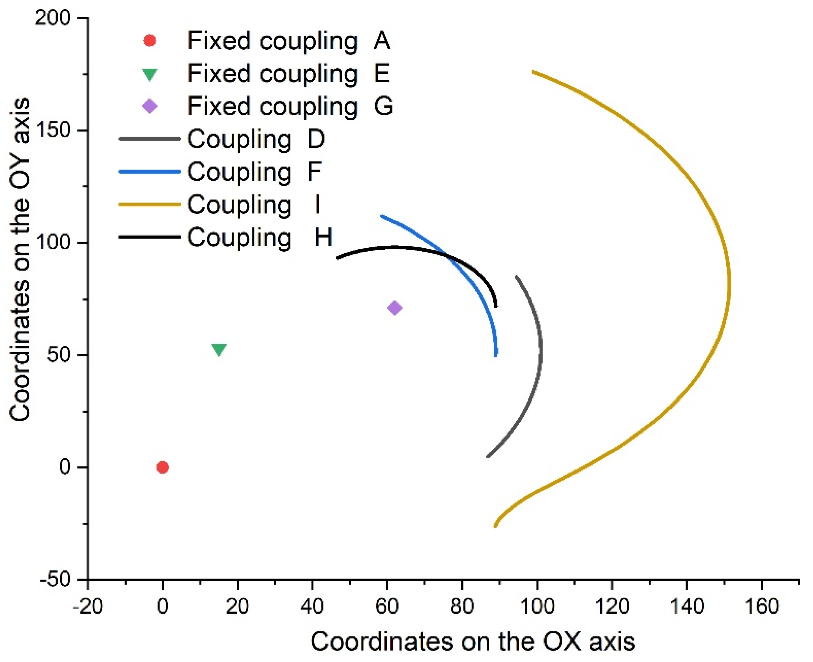
The results obtained using the calculation relationships presented in the previous chapter (relationships 1–20) are graphically presented in Figure 8. The values obtained were calculated based on the specific parameters previously presented, corresponding to each calculation relationship, and are essential for a complete understanding of the movement of the analyzed mechanism. By applying these values in the calculation relationships, a clear picture of the operation and efficiency of the studied mechanism is provided.
Following the analysis of the graphical representation in Figure 9, the following conclusions can be drawn:
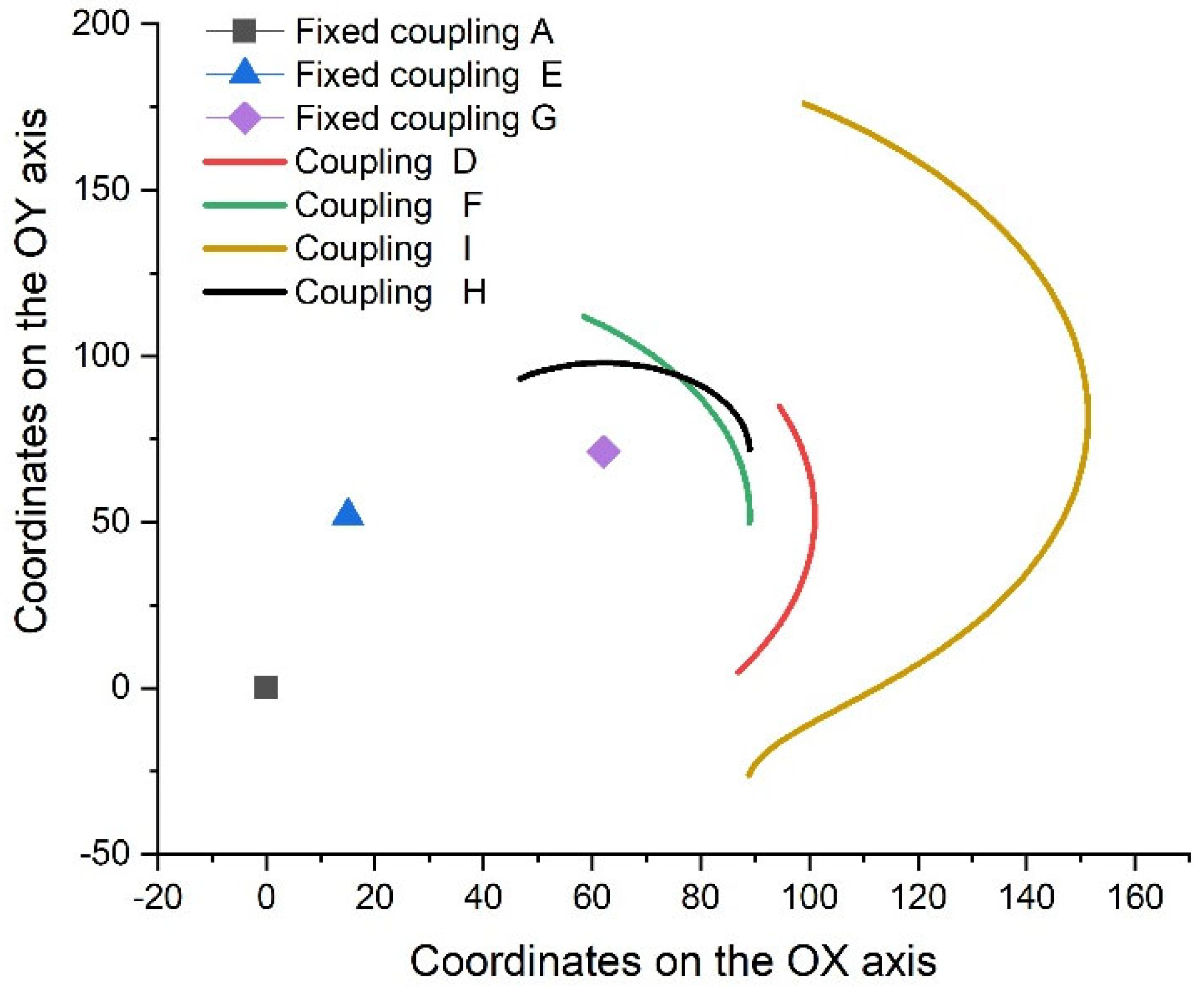
  • It is observed that the studied mechanism has the role of converting the linear motion generated by the hydraulic piston (according to Figure 1) into partial rotational motion. At the same time, the entire mechanism assembly serves to amplify the motion, specifically from the linear variation of 40 cm produced by the hydraulic piston (which is found in the variation of the dimensional element l1) to a motion performed by the motion coupling I, which is 283 cm.
  • Distribution of fixed couplings: Fixed couplings A, E, and G are positioned at different points on the graph (corresponding to the initially imposed coordinates), indicating their specific locations within the mechanical system. These fixed points are essential for the stability and operation of the mechanism.
  • Trajectories of mobile couplings: Couplings D, F, H, and I are represented by curves, indicating their trajectories during the operation of the mechanism. These trajectories show how the mobile components move in relation to the fixed points. These curved trajectories are influenced by:
    The position of the couplings in relation to the driving element;
    The position of the couplings in relation to the fixed couplings of the mechanism;
    The size of the elements they are part of.
The graph provides valuable information for the kinematic analysis of the mechanism, allowing engineers to study the relative movements of the components. Additionally, the theoretical chapter highlighted the calculation relationships corresponding to angular values that some elements of the mechanism generate in relation to the OX axis.
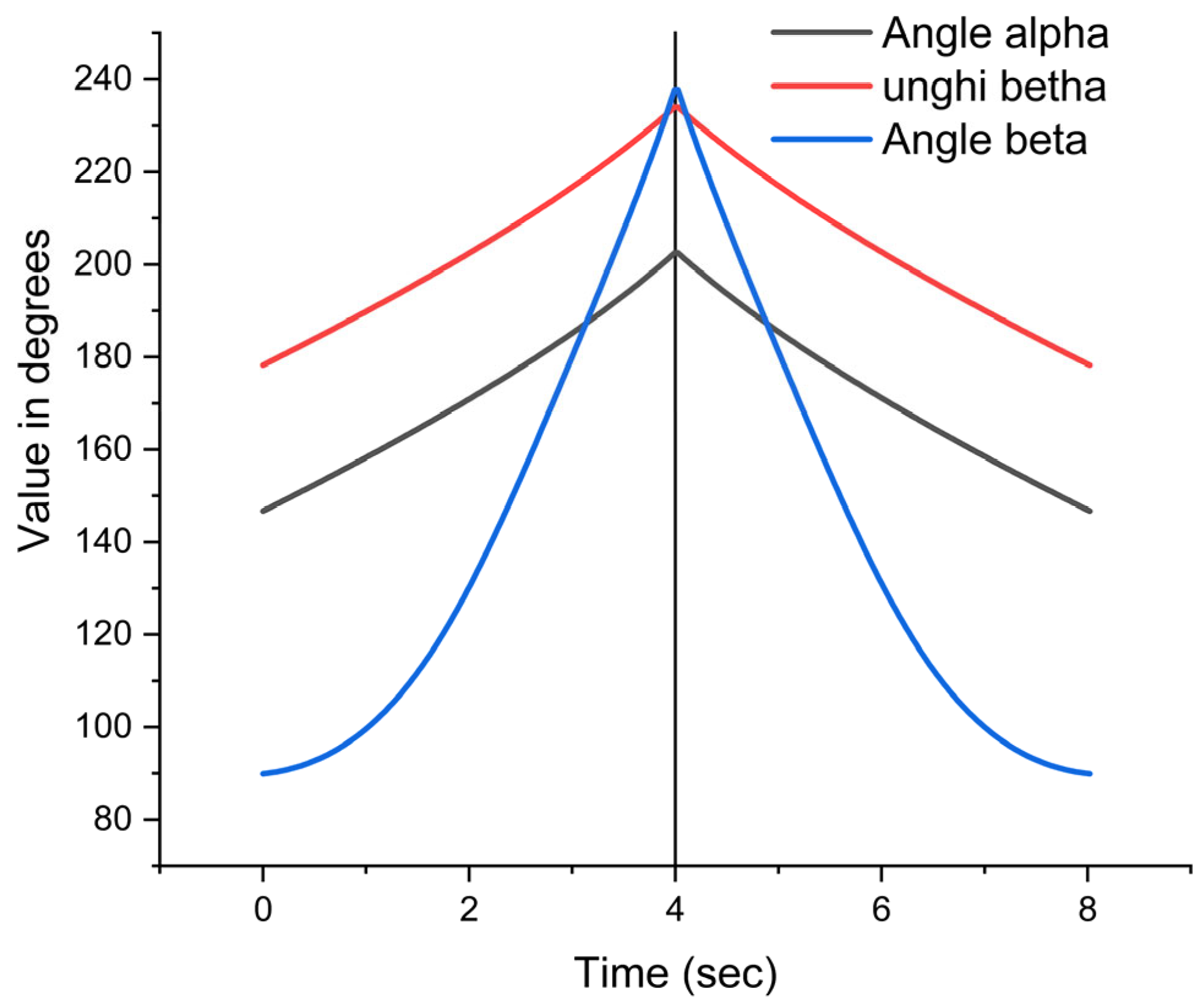
These variations are presented in Figure 9 and correspond to a complete cycle of the mechanism (i.e., lifting and lowering the load).
Analyzing the variations of the three mathematically determined angles, it can be observed that:
  • As a general characteristic of variation, it is observed that all three angles vary according to a roughly similar pattern, namely increasing until the time of 4 s, followed by a decrease in value. This interdependence results from the existence of a mechanical system in which all three angles are dependent on each other;
  • Both angles α and β exhibit the same linear growth trend. This is because the two angles are generated by the components of the ternary element EFD presented in Figure 5, thus highlighting the direct relationship between the structure of the EFD element and the variation of the angles.
  • Regarding the variation of angle γ, it can be said that it exhibits a parabolic variation, starting from a value of approximately 90 degrees and reaching 130.1 degrees when we have the value of 2 s. After 2 s, the value of the analyzed angle increases linearly, reaching 237.79 degrees at 4 s. The initial parabolic shape suggests an accelerated increase in angle γ, while the subsequent linear increase indicates a stabilization of the rate of change.

5. Discussion

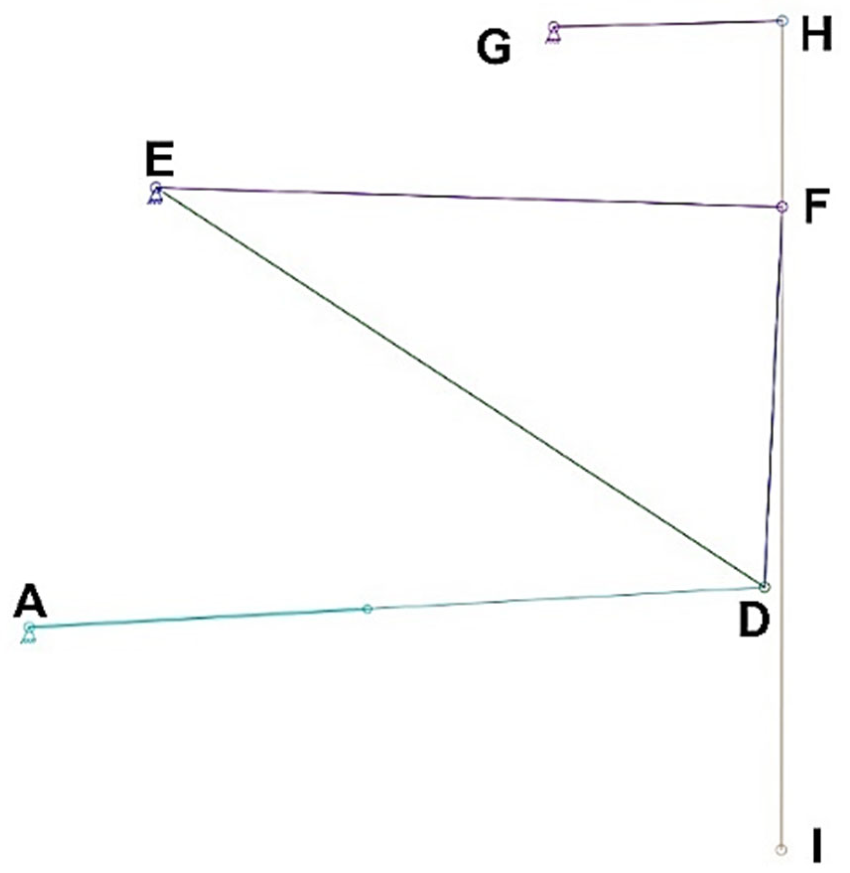
To verify the accuracy of the obtained values, specifically those corresponding to the coordinates of the moving couplings, the simulation program Linkage v.3.16.14 was used [53]. The presentation mode of the mechanism is visualized in Figure 1 (shown using the “solid” drawing mode). For a clearer understanding of this mechanism, Figure 10 presents the mechanism while respecting the notations from Figure 2.
Analyzing the representations of the mechanism in Figure 1 and Figure 10, it is observed that they are not identical. This is because:
  • Figure 1 is a sketch of the studied mechanism on which the mathematical calculation was based;
  • Figure 10 presents the same mechanism but considers the dimensional values of the elements it is composed of.
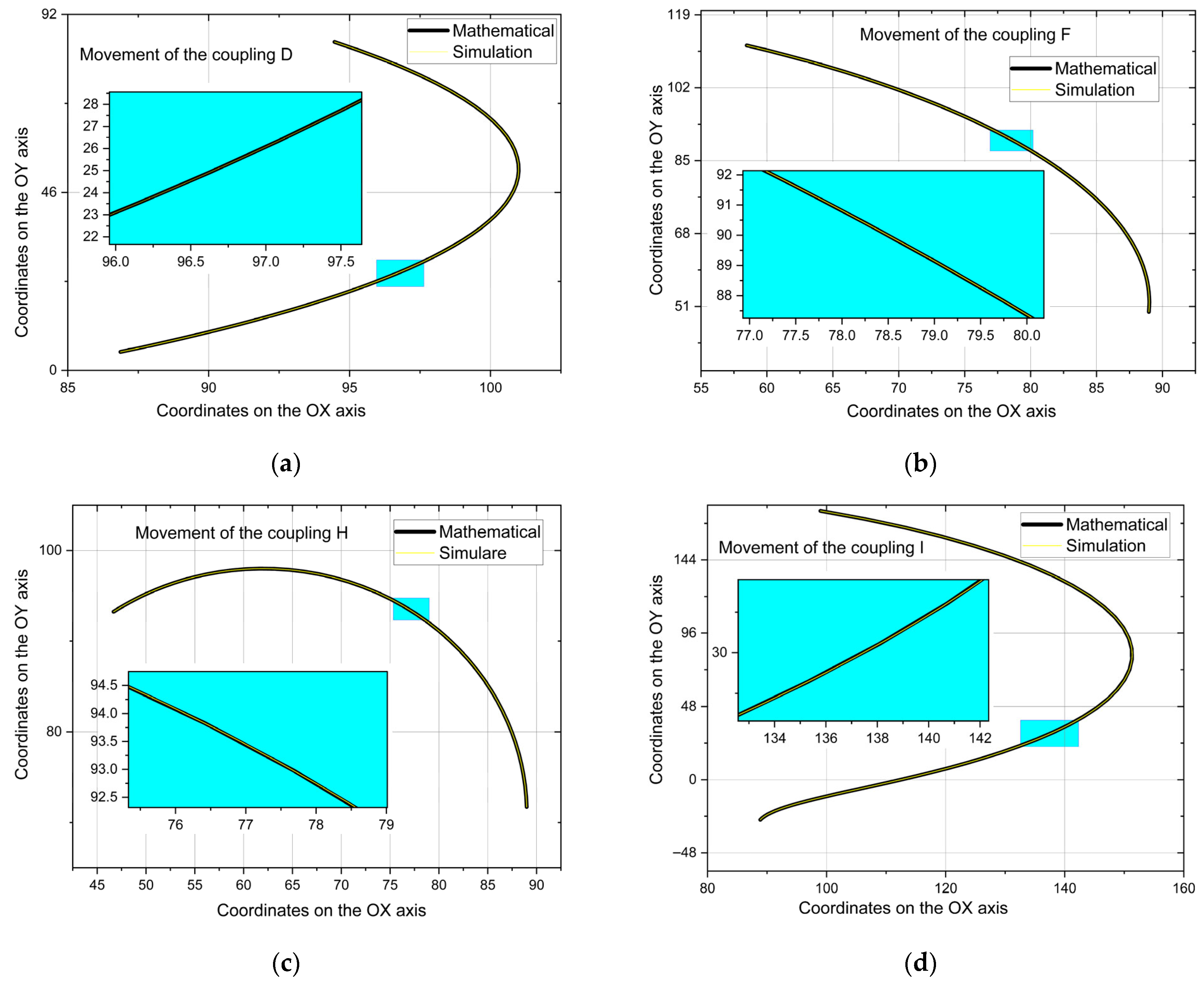
The Linkage v.3.16.14 program allows, in addition to visualizing the motion executed by the elements of the mechanism, export of the position values on the OX and OY axes of the couplings that execute motion. These values were used to create the graphical representation in Figure 11. It should be noted that the number of values generated by the Linkage v.3.16.14 program for the trajectories of couplings D, F, H, and I was 244 (corresponding to the lifting and lowering action of the garbage bin).
By overlaying the trajectories of the main dynamic elements of the mechanism (couplings D, F, H, and I) obtained from the two types of analyses, mathematical and simulation (represented in Figure 12), it is observed that there is not a big difference between the two. This indicates that the relationships used to determine the position variation of the moving couplings D, F, H, and I are correct. Table 1 shows the difference between the distance traveled by mobile couplings between two consecutive positions.
As previously mentioned, it was not possible to identify the calculation relationships for determining the linear velocities corresponding to the couplings studied due to the complexity of the mechanical structural group used (presented in Figure 5 and Figure 6). However, it was possible to determine:
  • For the values obtained mathematically, the method of determining the distance between two consecutive points (based on the coordinates on the OX and OY axes of the point) was applied relative to the time interval. In this method, the travel time between points is 0.08 s.
  • The Linkage v.3.16.14 simulation program not only provides the values of the coordinates of the studied points but also allows the determination and export of the linear velocity values of these points, all in a single file.
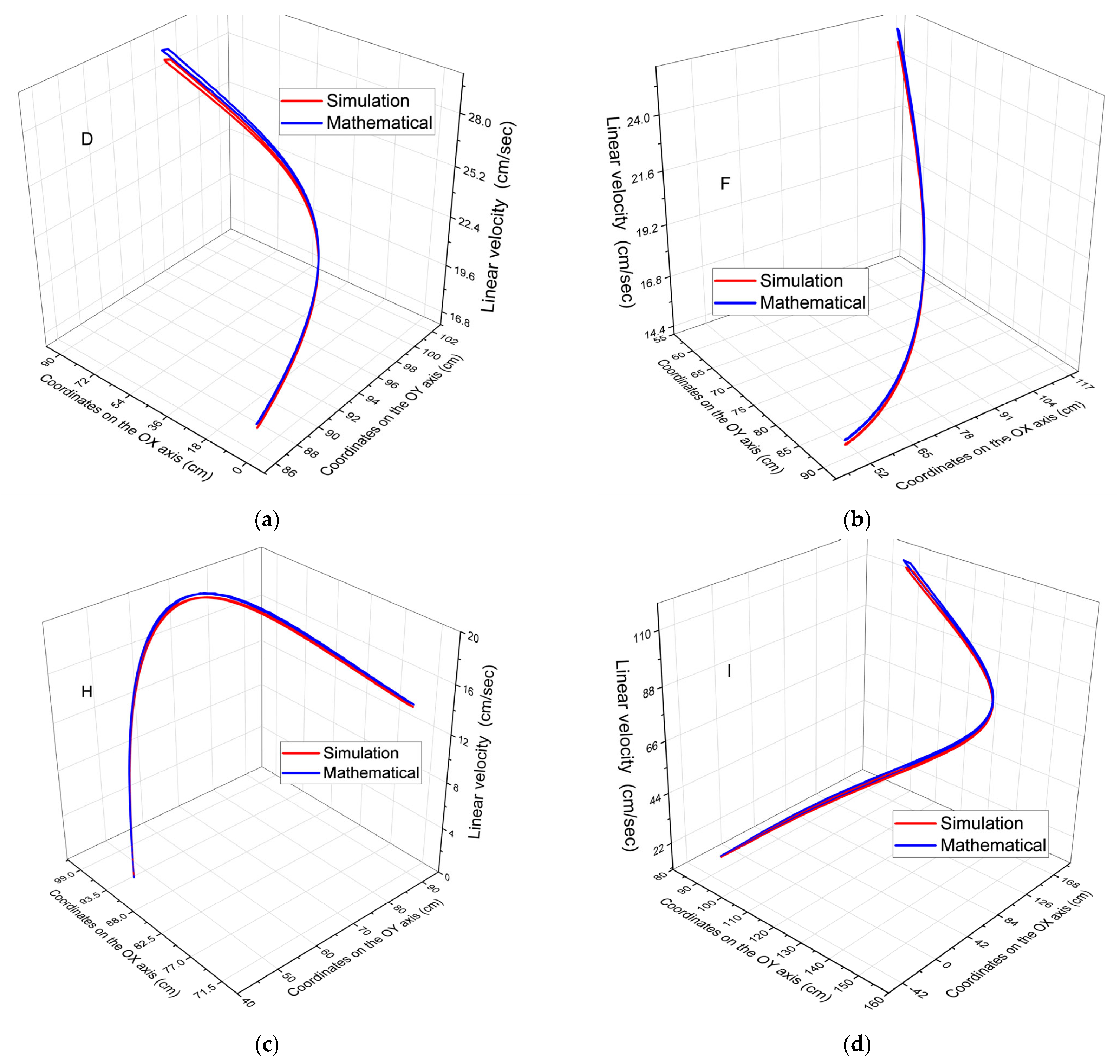
Based on this information, a comparative study of the linear velocities for the coupling studied was also carried out. Figure 13 shows this variation of linear velocities in relation to the coordinates of each coupling. It should be noted that these variations of the presented parameter are specific to the dimensional characteristics used for verification.
By analyzing the graphical representations in Figure 13, it can be concluded that:
  • Since couplings D and F are parts of the same mechanical component (the ternary element DEF), they exhibit the same variation in linear velocity relative to the trajectory of the analyzed couplings, specifically in an arc shape.
  • The variation in coupling H shows a rapid increase in velocity in the initial part of the stroke, followed by a slow decrease.
  • The velocity variation in coupling I is presented in the form of a half-spiral.
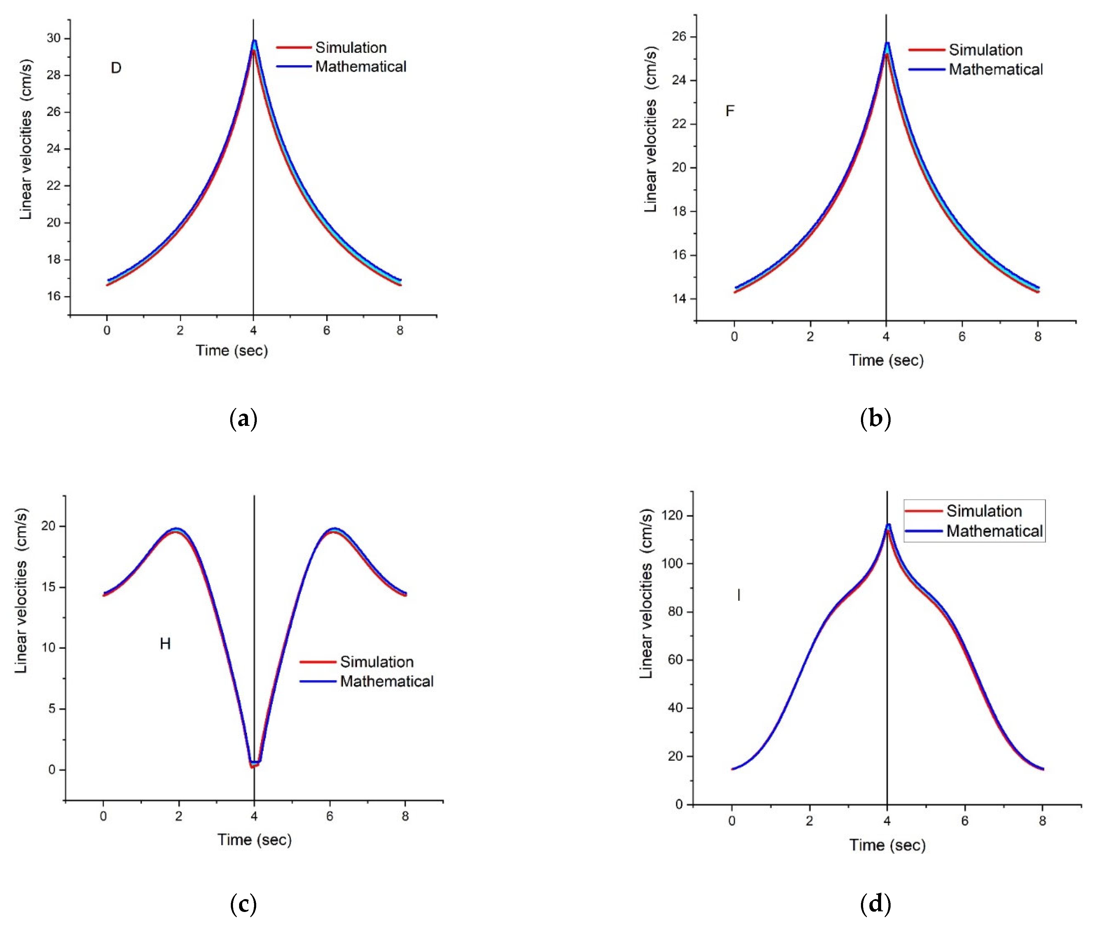
Figure 14 presents the same parameter, but the representation is based on the time interval.
When making the comparison, it is important to consider that the graph corresponding to the determination shows the following conclusions from analyzing the graphical representations in Figure 14:
  • Regardless of the figure referred to, the pattern of the parameter variation is the same for both the mathematical calculation method and the simulation method.
  • It is also observed that regardless of which coupling is analyzed, the variation in linear velocity is mirrored. The reference element is specific to the time value of 4 s. This value corresponds to the time when the mechanism reaches the end of its stroke, specifically when the hydraulic piston (specific to element AD) completes its maximum stroke.
  • Regarding the variation pattern of the studied parameter, it is observed that:
    Both coupling D and coupling F exhibit the same pattern of linear velocity variation. Starting from a low value, the velocity increases exponentially until the completion of the load lifting stroke, followed by a decrease that follows the same trend. This similarity in the variation of the studied parameter is because both couplings are part of the same ternary element DFE;
    Regarding the variation in the velocity of coupling H, it is observed that after a period of 2 s during which the velocity increases exponentially, it then decreases to almost 0 cm/s (0.655 cm/s) when it reaches the end of the stroke;
    For coupling I, which is specific to the movement of the end of the mechanism used for lifting the load, it is observed that although the velocity varies exponentially, at the midpoint of the stroke (both during lifting and lowering the load), a decrease in velocity was obtained.
  • Analyzing the difference between the values obtained mathematically and those obtained through the Linkage v.3.16.14 simulation program, it is observed that:
    For coupling D, the largest difference was 0.66 cm/s, and this difference appears at the end of the load lifting operation. The smallest difference between the two methods occurs at the start of the load and at the end of the lowering operation (at times 0.132 s and 7.953 s) and is 0.23 cm/s.
    The largest difference for coupling F is also observed at the end of the load lifting operation (specifically 0.57 cm/s at 3.96 s). Like coupling D, the smallest difference is obtained under the same conditions, specifically 0.19 cm/s at times 0.066 s and 0.792 s.
    For coupling H, the smallest difference between values is observed at 4.62 s (specifically 0.0026 cm/s), while the largest difference is observed at 3.927 s (specifically 0.45 cm/s).
    Compared to the other couplings, the maximum difference between the values obtained by the two different methods for coupling I is 3.18 cm/s, while the minimum is 0.17 cm/s.
Regardless of which coupling is analyzed, it is observed that the values obtained mathematically are higher compared to those obtained through simulation.

6. Conclusions

The development of this study demonstrates that new calculation methods for mechanical systems, particularly in structural analysis, can still be advanced. This article presents a kinematic study of a mechanism designed for lifting loads, specifically a household garbage bin. The specialized literature contains numerous lifting systems used by auto-compactors for waste collection.
In this article, a detailed kinematic analysis of such a system was performed, highlighting the following:
  • New types of equations were identified to describe the motion of the primary couplings specific to the analyzed mechanism.
  • To derive these new calculation relationships, the mechanism was decomposed into structural groups. In this study, only three structural groups were used, compared to five required by the classical method. This reduced number simplifies the analysis while maintaining its effectiveness in determining the motion of each component.
  • Due to the way the structural groups were defined, the resulting equations are more complex than those typically found in the existing literature.
  • The kinematic analysis was conducted without assigning numerical values, resulting in equations of a general character. These equations can be applied to this type of lifting mechanism for any set of dimensional parameters, provided the basic functional conditions of the mechanism are preserved.
  • The developed calculation relationships are not limited to specific construction cases, making them applicable to a wide range of industrial mechanisms.
  • The use of the Linkage v.3.16.14 simulation program enabled verification of the mathematical results and provided a clear visualization of the mechanism’s operation.
  • The variations in the studied parameters, including the coordinates of kinematic couplings, the angles formed by the elements relative to the OX axis, and the linear velocities at the couplings, are consistent, displaying periodic and symmetrical behavior over the analyzed time interval (corresponding to the movement of the mechanism’s actuating element, the hydraulic piston).
This study makes a significant scientific contribution to the field of kinematic analysis of lifting mechanisms by formulating a set of general mathematical relationships, obtained through the reduction of the number of structural groups used in modeling. Unlike classical approaches, which typically involve decomposition into five groups, this study proposes an innovative methodology based on only three structural groups, demonstrating that this simplification does not compromise the accuracy of the analysis but rather optimizes it. The scientific contribution lies in the development of an extensible theoretical framework that allows the application of the computational relationships to a wide range of mechanisms, regardless of their constructive dimensions, provided that functional principles are respected. The validation of these relationships through simulation in Linkage v.3.16.14 confirms the robustness of the proposed model.
Thus, the article not only offers an efficient engineering solution but also establishes a general methodology for kinematic analysis, with potential for extension in future research on dynamic modeling and optimization of complex mechanisms.
This study contributes to the specialized literature by identifying complex yet general calculation relationships that accurately describe the motion of the studied mechanism’s components. The theoretical analysis aims to enhance the performance of industrial equipment and foster technological progress, providing engineers with valuable tools for designing new and innovative mechanisms.
To expand on the contributions of this study, future research could focus on dynamic modeling of the mechanism, including effects such as friction and inertia [55]. Such an approach would complement the current kinematic analysis and enable simulation of the actual behavior of the system under variable load and speed conditions, providing a solid basis for improving the performance and reliability of the mechanism.
Although the article presents both an analytical approach and a simulation-based one (using Linkage v.3.16.14), a critical analysis of the advantages and limitations of each method has not been conducted. A more detailed comparative evaluation is required in a future study, aiming to highlight: (1) the accuracy and applicability of the analytical relationships in various contexts, (2) the simulation’s ability to capture complex behaviors of the mechanism, and (3) the potential limitations of both methods in relation to data obtained from real-world experiments. Such an analysis would enable a deeper understanding of the field and support the selection of the most appropriate method depending on the research objective.
The conclusions of the study confirm the achievement of the research objective, namely the formulation of general computational relationships for lifting mechanisms, obtained by reducing the number of structural groups. Although the proposed model is mathematically more complex, it offers increased flexibility in application. The minor discrepancies between the analytical model and the simulation indicate good correspondence, but full validation requires comparison with data from real-world experiments. Therefore, in order to strengthen the validity of the proposed model and demonstrate its correspondence with the actual object of research, a comparison with results obtained from natural experiments is necessary. In this regard, it is proposed that a future study include direct measurements on a real lifting and emptying mechanism (made from various materials: composite materials, light alloys, or hybrid structures, e.g., combinations of metallic elements and reinforced polymers), which can reduce the total weight without compromising mechanical strength. This mechanism, being in operation, would allow the collection of data regarding trajectories, linear velocities, and angular variations of the mobile joints. These experimental data will enable a rigorous comparison with the results obtained through analytical methods and the simulations performed in Linkage v.3.16.14, thus providing full validation of the theoretical model. The integration of these results will contribute to confirming the applicability of the general computational relationships formulated in this article and will reinforce the conclusions regarding the efficiency of structural group reduction in kinematic analysis.

Author Contributions

Conceptualization, E.M.; methodology, E.M.; software, E.M.; validation, I.W. and M.J.; formal analysis, D.C. and I.W.; investigation, N.S.; resources, M.J. and N.S.; data curation, C.T.; writing—original draft preparation, E.M., and D.M.; writing—review and editing D.C. and D.M.; visualization C.T., D.C., F.N. and D.M.; supervision, F.N. All authors have read and agreed to the published version of the manuscript.

Funding

This research received no external funding.

Data Availability Statement

The original contributions presented in this study are included in the article. Further inquiries can be directed to the corresponding authors.

Conflicts of Interest

The authors declare no conflicts of interest.

Abbreviations

The following abbreviations are used in this manuscript:
a, b, c, d, e, f, g, hthe dimensional values of the binary elements AB, CD, DE, EF, DF, GH, HF and FI are noted
xthe dimensional values of the binary elements BC are noted
l1the dimensional values of elements AD are noted
x0, y0coordinates of coupling A
x1, y1coordinates of coupling E
x2, y2coordinates of coupling G
dAEdistance between fixed couplings A and D
d1, d2, d3, d4, aa, bbare notations, made with the aim of reducing the dimensionality of the equations presented
α, β and γare the angles generated by the binary elements ED, EF and HI in relation to the horizontal axis

References

  1. Oliskevych, M.; Danchuk, V. An algorithm for garbage truck routing in cities with a fixation on container filling level. Transp. Probl. 2023, 18, 75–87. [Google Scholar] [CrossRef]
  2. Ando, R.; Mimura, Y. On relations of the consciousness of garbage truck drivers and their experiences of unsafe driving behaviors. Int. Rev. Spat. Plan. Sustain. Dev. 2015, 3, 25–35. [Google Scholar] [CrossRef]
  3. Ceballos, D.; Zhou, M.; Herrick, R. Metals and particulates exposure from a mobile e-waste shredding truck: A pilot study. Ann. Work Expo. Health 2020, 64, 890–896. [Google Scholar] [CrossRef] [PubMed]
  4. Vu, H.L.; Ng, K.T.W.; Fallah, B.; Richter, A.; Kabir, G. Interactions of residential waste composition and collection truck compartment design on GIS route optimization. Waste Manag. 2020, 102, 613–623. [Google Scholar] [CrossRef] [PubMed]
  5. Vecchi, T.P.B.; Surco, D.F.; Constantino, A.A.; Steiner, M.T.A.; Jorge, L.M.M.; Ravagnani, M.A.S.S.; Paraíso, P.R. A sequential approach for the optimization of truck routes for solid waste collection. Process Saf. Environ. 2016, 102, 238–250. [Google Scholar] [CrossRef]
  6. Sulemana, A.; Donkor, E.A.; Forkuo, E.K.; Oduro-Kwarteng, S. Optimal routing of solid waste collection trucks: A review of methods. J. Eng. 2018, 2018, 4586376. [Google Scholar] [CrossRef]
  7. Sulemana, A.; Donkor, E.A.; Forkuo, E.K.; Asantewaa, J.; Ankrah, I.N.A.; Musah, A.M.O. Optimized routing of trucks for institutional solid waste collection in kumasi, Ghana. Detritus 2020, 9, 50–58. [Google Scholar] [CrossRef]
  8. De Santis, M.; Silvestri, L.; Forcina, A.; Di Bona, G.; Di Fazio, A.R. Preliminary realization of an electric-powered hydraulic pump system for a waste compactor truck and a techno-economic analysis. Appl. Sci. 2021, 11, 3033. [Google Scholar] [CrossRef]
  9. Zubov, V.V.; Domnitskiy, A.A.; Kargin, R.V. Calculation and choice of grip parameters for garbage truck manipulator. Procedia Eng. 2015, 129, 896–902. [Google Scholar] [CrossRef]
  10. Olszowiec, P.J.T. Garbage truck operation in an urban area. Int. J. Mar. Navig. Saf. Sea Transp. 2021, 15, 911–914. [Google Scholar] [CrossRef]
  11. Lu, W.; Yuan, L.; Lee, W.M.J.E.S.; Research, P. Understanding loading patterns of construction waste hauling trucks: Triangulation between big quantitative and informative qualitative data. Environ. Sci. Pollut. Res. 2022, 29, 50867–50880. [Google Scholar] [CrossRef] [PubMed]
  12. Holenko, K.; Dykha, O.; Koda, E.; Kernytskyy, I.; Horbay, O.; Royko, Y.; Fornalchyk, Y.; Berezovetska, O.; Rys, V.; Humenuyk, R.J.A.S. Structure and strength optimization of the Bogdan ERCV27 electric garbage truck spatial frame under static loading. Appl. Sci. 2024, 14, 11012. [Google Scholar] [CrossRef]
  13. Wang, Z.C.; Liu, D.W.; Jiang, R.C.; Ge, X.K. Optimum design of kitchen garbage truck lifting mechanism based on virtual prototype. Adv. Mater. Res. 2012, 479–481, 837–840. [Google Scholar] [CrossRef]
  14. Glazunov, V.; Albagachiev, A.Y.; Erofeev, M.; Romanov, A.A. Development and investigation of a parallel-structure mechanism with toothed gears taking into account friction. J. Mach. Manuf. Reliab. 2022, 51, 143–152. [Google Scholar] [CrossRef]
  15. Wen, Y.; Lu, Y. A comparative study of garbage classification practice in different countries. In ICMSEM 2020, Proceedings of the International Conference on Management Science and Engineering Management, Chișinău, Moldova, 30 July–2 August 2020; Xu, J., Duca, G., Ahmed, S., García Márquez, F., Hajiyev, A., Eds.; Springer: Cham, Switzerland, 2021; Volume 1191, pp. 603–612. [Google Scholar]
  16. Wu, T.H.; Chen, P.Y. Battery management system for electric garbage compactor trucks. IEEE Access 2024, 12, 88596–88607. [Google Scholar] [CrossRef]
  17. Souza, R.V.D.; Pinto, J.M.A.; Cimini, C.A.; Pereira, S.L.D. Evaluation of pitch up of two-axle solid waste collection compactor trucks in the static condition. Waste Manag. Res. 2011, 29, 340–348. [Google Scholar] [CrossRef] [PubMed]
  18. Wang, B.; Tao, J.; Wu, H.P. The Application of knowledge representation on the design of loading device of garbage truck. Appl. Mech. Mater. 2012, 121–126, 3568–3572. [Google Scholar] [CrossRef]
  19. Dang, T.D.; Do, T.C.; Ahn, K.K. Experimental assessment of the power conversion of a wave energy converter using hydraulic power take-off mechanism. Int. J. Precis. Eng. Manuf.-Green Technol. 2021, 8, 1515–1527. [Google Scholar] [CrossRef]
  20. Wójcik, W.; Bereziuk, O.V.; Lemeshev, M.S.; Bohachuk, V.V.; Polishchuk, L.K.; Bezsmertna, O.; Smailova, S.; Kurmagazhanova, S. Metrological aspects of controlling the rotational movement parameters of the auger for dewatering solid waste in a garbage truck. Int. J. Electron. Telecommun. 2023, 69, 233–238. [Google Scholar] [CrossRef]
  21. Parczewski, K.; Wnek, H. Influence of clearance on the rocker arm pin on the steerability and stability of the vehicle motion. Energies 2021, 14, 7827. [Google Scholar] [CrossRef]
  22. Zhou, Z.G.; Zhao, J.Y.; Zhang, L.C.; Han, E.; Yan, G.F. Test method for energy consumption of hybrid compression garbage truck. In Proceedings of the 2014 IEEE Conference and Expo Transportation Electrification Asia-Pacific (ITEC Asia-Pacific), Beijing, China, 31 August–3 September 2014. [Google Scholar]
  23. Zheng, S.P.; Yang, Z.J.; Xu, L. Research on the Topology Optimization of the rocker arm of compression garbage truck based on Rigid-Flexible coupling. IOP Conf. Ser. Mater. Sci. Eng. 2018, 423, 012107. [Google Scholar] [CrossRef]
  24. Sun, Q.; Li, G.X.; Bai, S.Z.; Ma, C.C. The simulation study of hybrid compression garbage trucks. Adv. Mater. Res. 2013, 608–609, 1220–1224. [Google Scholar] [CrossRef]
  25. Emilian, M.; Valentin, N.; Narcis, B.; Alexandra-Dana, C.; Dragoş, R. Influence of screening block supporting way on the behaviour of a solid particle on an oscillating surface. J. Eng. Stud. Res. 2016, 21, 51–58. [Google Scholar] [CrossRef]
  26. Iqbal, A.; Veer, S.; Gu, Y. Analytical solution to a time-varying LIP model for quadrupedal walking on a vertically oscillating surface. Mechatronics 2023, 96, 103073. [Google Scholar] [CrossRef]
  27. Mosnegutu, E.; Nedeff, V.; Bontas, O.; Barsan, N.; Chitimus, D.; Rusu, D. Determination of kinematic indices corresponding to a solid particle on a flat oscillating surface. IOP Conf. Ser. Mater. Sci. 2016, 147, 012151. [Google Scholar] [CrossRef]
  28. Liu, C.; Wang, J.; Zhang, W.; Yang, X.-D.; Guo, X.; Liu, T.; Su, X. Synchronization of broadband energy harvesting and vibration mitigation via 1:2 internal resonance. Int. J. Mech. Sci. 2025, 301, 110503. [Google Scholar] [CrossRef]
  29. Escobar, L.; Bolanos, E.; Bravo, X.; Comina, M.; Hidalgo, J.L.; Ibarra, A. Kinematic resolution of delta robot using four bar mechanism theory. In Proceedings of the 2017 IEEE International Conference on Mechatronics and Automation (ICMA), Takamatsu, Japan, 6–9 August 2017; pp. 881–887. [Google Scholar] [CrossRef]
  30. Sabzali, H.; Koochakzadeh, E.; Moradi, A.; Akbarzadeh, A. Kinematics and dynamics optimization of a novel non-circular gear-attached four-bar mechanism for knee exoskeleton robot. In Proceedings of the 2022 10th RSI International Conference on Robotics and Mechatronics (ICRoM), Tehran, Iran, 22–24 November 2022; pp. 190–195. [Google Scholar] [CrossRef]
  31. El-Shakery, S.; Ramadan, R.; Khader, K. Analytical and graphical optimal synthesis of crank-rocker four bar mechanisms for achieving targeted transmission angle deviations. Jordan J. Mech. Ind. Eng. 2020, 14, 303–313. [Google Scholar]
  32. Jia, G.; Li, B.; Dai, J.S. Oriblock: The origami-blocks based on hinged dissection. Mech. Mach. Theory 2024, 203, 105826. [Google Scholar] [CrossRef]
  33. Ding, X.; Yang, Y.; Dai, J.S.J.M.; Theory, M. Topology and kinematic analysis of color-changing ball. Mech. Mach. Theory 2011, 46, 67–81. [Google Scholar] [CrossRef]
  34. Boskovic, M.; Bulatovic, R.R.; Salinic, S.; Miodragovic, G.R.; Bogdanovic, G.M. Optimization of dynamic quantities of a four-bar mechanism using the Hybrid Cuckoo Search and Firefly Algorithm (H-CS-FA). Arch. Appl. Mech. 2018, 88, 2317–2338. [Google Scholar] [CrossRef]
  35. Flores-Pulido, L.; Portilla-Flores, E.A.; Santiago-Valentin, E.; Vega-Alvarado, E.; Yanez, M.B.C.; Nino-Suarez, P.A. A Comparative study of improved harmony search algorithm in four bar mechanisms. IEEE Access 2020, 8, 148757–148778. [Google Scholar] [CrossRef]
  36. Qaiyum, A.; Mohammad, A. A novel approach for optimal synthesis of path generator four-bar planar mechanism using improved harmony search algorithm. Aust. J. Mech. Eng. 2024, 22, 95–108. [Google Scholar] [CrossRef]
  37. Wang, B.; Du, X.C.; Ding, J.Z.; Dong, Y.; Wang, C.J.; Liu, X.A. The synthesis of planar four-bar linkage for mixed motion and function generation. Sensors 2021, 21, 3504. [Google Scholar] [CrossRef]
  38. Bandopadhya, D.; Njuguna, J. Modelling and analysis of an ionic polymer-metal composite (IPMC)-rocker-based four-bar for variable path generation using the Euler-Bernoulli approach. Proc. Inst. Mech. Eng. Part C J. Mech. Eng. Sci. 2009, 223, 2405–2411. [Google Scholar] [CrossRef]
  39. Cakar, O.; Tanyildizi, A.K. Application of moving sliding mode control for a DC motor driven four-bar mechanism. Adv. Mech. Eng. 2018, 10, 1687814018762184. [Google Scholar] [CrossRef]
  40. Ge, Q.J.; Purwar, A.; Zhao, P.; Deshpande, S. A Task-driven approach to unified synthesis of planar four-bar linkages using algebraic fitting of a pencil of g-manifolds. J. Comput. Inf. Sci. Eng. 2017, 17, 031011. [Google Scholar] [CrossRef]
  41. Arman, R.; Mahyuddin, A.I.; Marthiana, W.; Satria, I. Experimental investigation of vibration response of a flexible coupler in a four bar mechanism due to varying crank length and crank speed. MATEC Web Conf. 2018, 248, 01008. [Google Scholar] [CrossRef]
  42. Diab, N. A new graphical technique for acceleration analysis of four bar mechanisms using the instantaneous center of zero acceleration. SN Appl. Sci. 2021, 3, 327. [Google Scholar] [CrossRef]
  43. Meijaard, J.P.; van der Wijk, V. Principal vectors and equivalent mass descriptions for the equations of motion of planar four-bar mechanisms. Multibody Syst. Dyn. 2020, 48, 259–282. [Google Scholar] [CrossRef]
  44. Zhang, K.; Yang, M.W.; Zhang, Y.M.; Huang, Q.J. Error feedback method (EFM) based dimension synthesis optimisation for four-bar linkage mechanism. Appl. Soft Comput. 2023, 144, 110424. [Google Scholar] [CrossRef]
  45. Bustamante, M.; Vega-Centeno, R.; Sánchez, M.; Mio, R. A parametric 3D-printed body-powered hand prosthesis based on the four-bar linkage mechanism. In Proceedings of the 2018 IEEE 18th International Conference on Bioinformatics and Bioengineering (BIBE), Taichung, Taiwan, 29–31 October 2018; pp. 79–85. [Google Scholar] [CrossRef]
  46. Liu, Y.; Yang, S. Kinematic solution of spherical Stephenson-III six-bar mechanism. Chin. J. Mech. Eng. 2013, 26, 851–860. [Google Scholar] [CrossRef]
  47. Zuczek, R.; Pysz, S.; Maj, M.; Pieklo, J. Shaping the strength of cast rocker arm for special purpose vehicle. Arch. Foundry Eng. 2015, 15, 95–98. [Google Scholar] [CrossRef]
  48. Wei, W.H.; Shen, J.C.; Yu, H.P.; Chen, B.R.; Wei, Y. optimization design of the lower rocker arm of a vertical roller mill based on ANSYS Workbench. Appl. Sci. 2021, 11, 10408. [Google Scholar] [CrossRef]
  49. Xu, W.H.; Zhang, C.S.; Wang, S.Y. Design and simulating analysis of compressed garbage transport truck lifting mechanism based on ADAMS. Appl. Mech. Mater. 2012, 215–216, 1224–1227. [Google Scholar] [CrossRef]
  50. Shi, G.L.; Chen, S.X.; Liang, G.M.; Shi, G.L. Analysis with ADAMS/ANSYS on dynamic properties of rotating hook-lift garbage truck. In Proceedings of the 2009 International Conference on Measuring Technology and Mechatronics Automation, Zhangjiajie, China, 11–12 April 2009; pp. 746–749. [Google Scholar] [CrossRef]
  51. Attia, E.M.; Abd El-Naeem, M.A.; El-Gamal, H.A.; Awad, T.H.; Mohamed, K.T. Simulation of the motion of a four bar prosthetic knee mechanism fitted with a magneto-rheological damper. J. Vibroeng. 2016, 18, 4051–4068. [Google Scholar] [CrossRef]
  52. Mo, X.J.; Ge, W.J.; Wang, S.C.; Zhao, D.L. Mechanical design and dynamics simulation of locust-inspired straight line four-bar jumping mechanism. In Mechanism and Machine Science. ASIAN MMS CCMMS 2016; Lecture Notes in Electrical Engineering; Springer: Singapore, 2017; Volume 408, pp. 429–442. [Google Scholar] [CrossRef]
  53. Rector, D. Linkage Mechanism Designer and Simulator. Available online: https://blog.rectorsquid.com/linkage-mechanism-designer-and-simulator/ (accessed on 12 June 2024).
  54. Mathcad. Available online: https://www.mathcad.com/en (accessed on 27 July 2022).
  55. Hazem, Z.B.; Fotuhi, M.J.; Bingül, Z. A comparative study of the joint Neuro-Fuzzy friction models for a triple link rotary inverted pendulum. IEEE Access 2020, 8, 49066–49078. [Google Scholar] [CrossRef]
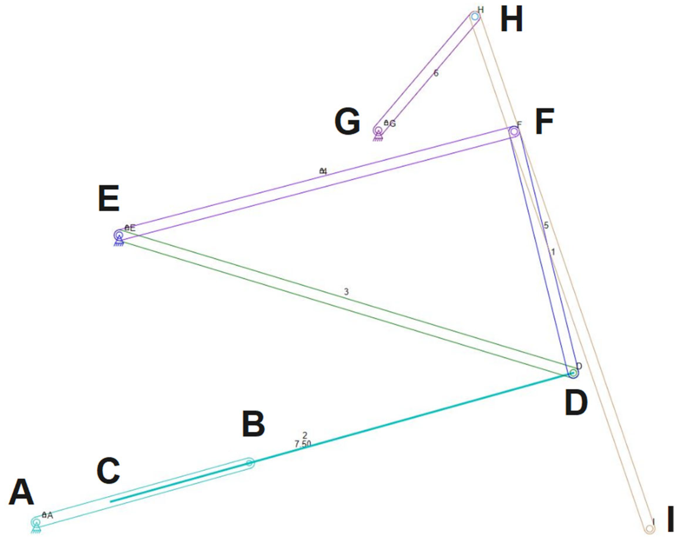
Figure 1. Presentation of the mechanism subjected to analysis using the Linkage v.3.16.14 program [53].
Processes 13 02744 g001
Figure 2. Working methodology.
Processes 13 02744 g002
Figure 3. Diagram of the studied mechanism.
Processes 13 02744 g003
Figure 4. Pneumatic/hydraulic piston: Group 1 of elements.
Processes 13 02744 g004
Figure 6. Group 3 of elements.
Processes 13 02744 g006
Figure 7. Variation of the telescopic component that actuates the studied mechanism.
Processes 13 02744 g007
Figure 8. Presentation of the movement of the different components of the mechanism.
Processes 13 02744 g008
Figure 9. Variation of the calculated angles.
Processes 13 02744 g009
Figure 10. Presentation of the mechanism used in the Linkage v.3.16.14 program.
Processes 13 02744 g010
Figure 11. Presentation of the results obtained through the Linkage v.3.16.14 program.
Processes 13 02744 g011
Figure 12. Comparative analysis between the results obtained by the two methods: (a) movement of coupling D; (b) movement of coupling F; (c) movement of coupling H; (d) movement of coupling I.
Processes 13 02744 g012
Figure 13. Variation in linear velocity based on the coordinates of the studied couplings: (a) for the movement of coupling D; (b) for the movement of coupling F; (c) for the movement of coupling H; (d) for the movement of coupling I.
Processes 13 02744 g013
Figure 14. Variation of linear velocities based on the time interval corresponding to an operating cycle: (a) movement of coupling D; (b) movement of coupling F; (c) movement of coupling H; (d) movement of coupling I.
Processes 13 02744 g014
Table 1. Presentation of the differences between the results obtained by the two working methods.
Mobile CouplingMinimum Difference (%)Maximum Difference (%)
D0.031.99
F0.031.89
H0.061.23
I0.017.09
Disclaimer/Publisher’s Note: The statements, opinions and data contained in all publications are solely those of the individual author(s) and contributor(s) and not of MDPI and/or the editor(s). MDPI and/or the editor(s) disclaim responsibility for any injury to people or property resulting from any ideas, methods, instructions or products referred to in the content.