Article

Effect of Additive Manufacturing Parameters on PLA, ABS, and PETG Strength

1
Department de Ciències i Enginyeria de Materials, Universitat Politècnica de Catalunya, Rambla de l’Exposició 24, 08800 Vilanova i la Geltrú, Spain
2
Department d’Enginyeria Gràfica i de Disseny, Universitat Politècnica de Catalunya, Rambla de l’Exposició 24, 08800 Vilanova i la Geltrú, Spain
3
Department of Materials Science and Chemical Engineering, Stony Brook University, Room 103 Heavy Engineering Building, Stony Brook, NY 11790, USA
4
Thermal Spray Center (CPT), Universitat de Barcelona, Carrer Martí i Franquès 1, 08028 Barcelona, Spain
*
Author to whom correspondence should be addressed.
Processes 2025, 13(9), 2733; https://doi.org/10.3390/pr13092733
Submission received: 30 July 2025 / Revised: 19 August 2025 / Accepted: 24 August 2025 / Published: 27 August 2025
(This article belongs to the Special Issue Additive Manufacturing of Materials: Process and Applications)

Abstract

Additive manufacturing has emerged as a promising technology to fabricate customized polymer parts, but the mechanical performance of printed components often falls short of bulk material properties. Among the different techniques, fused filament fabrication is the most accessible and widely adopted. However, previous studies addressing its processing parameters have produced fragmented or contradictory conclusions, limiting the ability to establish guidelines for mechanical optimization. This work addresses this gap by systematically investigating the influence of key parameters—extrusion temperature, printing speed, infill type and density, layer height, and number of walls—on the tensile properties of three commonly used thermoplastics: PLA, ABS, and PETG. A total of 495 standardized specimens were produced and tested under controlled conditions. The results demonstrate that increasing infill density and wall number consistently enhances tensile strength, with PLA showing an improvement of 1173 N when infill was raised from 20 to 80%, and PETG doubling its strength from 559 N with one wall to 1207 N with five walls. Layer height also had a positive effect, with PLA rising from 995 N at 0.10 mm to 1355 N at 0.30 mm. In contrast, higher printing speeds reduced mechanical performance (PLA decreased by 13% between 20 and 50 mm·s−1). Temperature exhibited material-dependent trends: PLA benefited up to 230 °C (+17%), while ABS strength decreased beyond 220 °C. Overall, the study provides a quantitative assessment of how processing parameters control mechanical reliability in polymer parts, offering practical guidelines for improved design and manufacturing.

1. Introduction

Additive manufacturing (AM), also known as 3D printing or rapid prototyping, has emerged as a transformative technology that enables the fabrication of complex three-dimensional objects by layering successive materials. Unlike traditional manufacturing methods, which typically involve material removal or forming, AM offers significant advantages in terms of design freedom, prototyping speed, and production efficiency [1,2,3,4]. This technique has been widely explored for many materials, including metals and alloys [5], concrete [6], polymers [7], and wood [8], among others, across numerous application domains such as orthopedic implants and human organs in the medical sector [3,9], repairing services of internal combustion engine parts [10], or prototyping new parts before a large-scale production [11].
To meet diverse material requirements, several AM techniques have been developed. Wire Arc (WAAM) [9], Selective Laser Sintering (SLS) or Melting (SLM) [12], and Cold Spray (CSAM) [5,12] have been applied for metals and alloys, while Fused Filament Fabrication (FFF), Material Extrusion (MEX) or Fused Deposition Modeling (FDM) [4], Stereolithography (SLA) [3], Digital Light Processing (DLP) [13], and Binder Jetting (BJ) [14] have been used to build polymer-based parts.
Among these, FFF stands out due to its accessibility, cost-effectiveness, and compatibility with a wide range of thermoplastic materials. However, it also presents limitations in surface quality and dimensional accuracy. In contrast, SLA offers superior resolution and surface finish, albeit at a higher cost and with complex post-processing requirements. SLS supports the use of high-performance polymers but can pose challenges in terms of surface quality and production cost [15,16,17].
Numerous studies have shown that FFF processing parameters significantly influence the mechanical performance of built parts. Onwubolu and Rayegani [18] concluded that a minimum layer thickness and raster width, and increasing the raster angle, improve tensile strength for ABS parts. Ziemian, Okwara, and Ziemian [19] measured the FFF-printed ABS tensile strength, which was much higher in the longitudinal direction of the printed wire than in its transversal direction, 25 and 9 MPa, respectively, supporting the need to optimize part design based on known or previewed application loads. Liu et al. [20] used the Taguchi statistical method to optimize FFF-printed PLA, achieving a tensile strength of 50 MPa under specific alignment and layer thickness conditions. Vraitch, Prince, and Souppez [2] observed a linear increase in strength with increasing infill density in PLA structures. Domingo-Espin et al. [21] demonstrated how printing parameters affect the elastic modulus of polycarbonate. Almonti, Salvi, and Ucciardello [22] investigated PETG honeycomb structures and confirmed its effectiveness as a shape-memory polymer, with over 95% elastic recovery. Similarly, for PTEG, Sri, Karthick, and Dinesh [23] showed that increasing infill density and printing speed led to a significant reduction in the compressive strength of PETG.
Regarding the part design, Silva et al. [24] concluded that the PLA-printed fibers, i.e., the fed wire aligned with the tensile loading direction, are much more resistant than the sample’s transversal direction due to a typical low bonding strength between the built layers. Besides this, increasing the Gyroid infill density from 20 to 80% resulted in an impact energy absorption of 6.1 and 189 J, respectively, which was proven to be material density-dependent because the energy density remained close to 1.55 kJ·mm2 for both structures. Hsueh et al. [25] described that FFF temperature improves the PLA stiffness and strength by promoting partial crystallization; however, excessive heating, i.e., >230 °C, can degrade the polymer. This microstructural change is less pronounced for ABS since it is inherently an amorphous polymer, and the deleterious effect of high temperature is more pronounced [26,27].
These findings highlight the need for a systematic understanding of how geometric design and process parameters influence the final properties of FFF-made parts. Establishing standardized guidelines for FFF fabrication could significantly improve quality, reproducibility, and performance in industrial and research settings. This work evaluates the effects of printing temperature and speed, as well as infill pattern and density, on the mechanical strength of three common polymers: PLA, ABS, and PETG. By isolating each parameter in a controlled experimental design, this study contributes to the optimization of FFF for enhanced tensile properties, offering insights valuable to both researchers and industry practitioners. Following the Introduction Section, the Materials and Methods Section presents the sample building and testing done in detail, presenting the parameters, equipment, and procedures used. The Results and Discussion Section lists and discusses the built samples’ characteristics and strengths. And finally, the Conclusions Section draws some deductions obtained from strength vs. FFF parameter interpretations.

2. Materials and Methods

2.1. Materials

To build the samples, three polymers were used as feedstock material in the form of dia. 1.75 mm solid wire. ABS and PLA have been the most used materials for AM research, as presented by Almuallim et al. [28]. PETG was added to them to form the group of the most popular filaments for FFF. These materials were selected to evaluate their behavior under different processing conditions and designs, and the raw material, i.e., the filament before any AM heating effect, was presented in the literature:
  • PLA (Polylactic Acid): Bio-based and biodegradable, popular for its ease of use and versatility. Supplied by NatureWorks LLC (Plymouth, MN, USA). PLA has a density of 1.25 g·cm−3, glass transition Tg of 137 °C, UTS of 53 MPa, and Young’s modulus of 3.5 GPa [29].
  • ABS (Acrylonitrile Butadiene Styrene): Amorphous polymer with high impact resistance, widely used in industrial settings. Supplied by Stratasys Ltd. (Rehovot, Israel). ABS has a density of 1.04 g·cm−3, glass transition Tg of 107 °C, UTS of 40 MPa, and Young’s modulus of 2.1 GPa [29].
  • PETG (Modified Polyethylene Terephthalate): Enhanced durability and mechanical strength, suitable for outdoor applications. Supplied by Prusa Research (Newark, DE, USA). PETG has a density of 1.27 g·cm−3, glass transition Tg of 71 °C, UTS of 50 MPa, and Young’s modulus of 2.0 GPa [29].

2.2. Samples Design and Processing Parameters

A BCN3D Technologies Epsilon W50 with a 0.4 mm nozzle (Sant Feliu de Llobregat (Barcelona), Spain) was used to build the samples. The study was conducted by testing a total of 495 specimens following UNE-EN ISO 527-2:2012 standard (Type 1A) [30], adhering to the plastics molding or extrusion testing model. For each condition, i.e., FFF parameter set and material, 5 specimens were tested.
The following printing parameters have been analyzed:
  • Infill type
Gyroid infill, Figure 1a, was invented at NASA in 1970 by Alan Schoen. It is a structure characterized by the absence of straight lines and being a triply periodic minimal surface (TPMS). This geometry is widely used in AM due to material savings and the robustness and strength it adds to the built piece compared to hollow structures [31,32].
Triangular shape, Figure 1b, provides balance to the user by obtaining pieces with superior mechanical strength compared to Gyroid infill while optimizing material usage compared to the grid pattern. However, in certain pieces and geometries, the final finish of the top layers may not be perfect.
The grid pattern, Figure 1c, was created by intersecting lines perpendicular to each other. It is one of the most used patterns in AM due to its reliability and repeatability, as the layers deposited always have support in two directions. Its main drawback is the material and printing time consumption, as a 20% infill with this pattern could be equivalent in surface area to a 12% Gyroid pattern. Therefore, it is estimated that the grid infill will provide greater strength, followed by the triangular infill, and, lastly, the Gyroid. The interesting aspect is to know to what extent each of them contributes to the strength, and whether the addition of this extra material compensates the user or not.
  • Infill density
It is expected that the infill density will affect the mechanical strength of the pieces proportionally. In other words, the more material is increased inside the piece, the more it will be able to withstand external stresses. This is not only due to the strength provided by the material itself but also to the adhesion between layers [33,34]. Figure 2 shows different infill densities of 20, 40, and 60%.
  • Layer height
One of the weak points of FFF is the adhesion between the layers of the piece. The performance of the bonding of each of these layers does not have the same mechanical strength as the material itself [21,34,35,36,37,38]. Therefore, the smaller the layer height, i.e., the more layers there are in the piece, the lower its performance. Layer height is generally chosen to achieve higher resolution or geometric accuracy and better surface finish or to save printing time. With this test, it is expected to add a factor to consider when choosing. Heights tested were 0.10, 0.15, 0.20, 0.25, and 0.30 mm.
  • Printing speed
The effect of this parameter on the final piece is the most complex to explain, as several factors can affect the AM result. It is important to note that higher speeds result in higher material extrusion. Speeds tested were 20, 30, 40, and 50 mm·s−1, which were chosen based on the literature and team expertise in using the FFF equipment.
  • AM temperature
A range of temperatures has been selected for each material based on the recommended printing temperature by each material manufacturer, as listed in Table 1. FFF temperature is the heat reached by the heat block. The literature presents that a lower temperature results in lower mechanical strength due to increased pressure and, therefore, an increased risk of material shortage. Conversely, a higher FFF temperature improves extrusion and layer adhesion, increasing mechanical strength.
  • Number of walls
The number of walls in a piece refers to a structural part of the piece itself, similar to the infill parameter. Walls define the contour of the piece [2,39]. Unlike infill structures, these walls are adjacent to each other, so the adhesion between the extruded threads is not only with the previous layer but also with the adjacent walls. Therefore, theoretically, increasing the number of walls will substantially increase the mechanical strength of the pieces. It is anticipated that the increase will be much more significant than the increase in infill alone. For this work, a single wall was 0.4 mm, defined by the print feeding/heater nozzle diameter, and multiple walls had a 20% overlap. The number of walls designed was: 1, 2, 3, 4, and 5.

2.3. Mechanical Strength Evaluation

To measure and evaluate the samples’ mechanical strength, a Shimadzu AGS-X Series (Kyoto, Japan) machine with a 10 kN force capacity is used to conduct tensile tests on the FFF specimens. The tensile tests of the samples were carried out following the standard UNE-EN ISO 527-2:2012 [30], including dimensions (Type 1A, Figure 3a), speed of 50 mm·min−1, and environmental temperature of 23 ± 2 °C and humidity of 50 ± 10%. Samples were built to standard dimensions instead of being cut from a built plate, ensuring compliance with standardized procedures for reliable and comparable results, and were conditioned at the testing conditions for 16 h before the tensile testing. A total of five samples for each material/condition/design were tested, and the results present the mean value and standard deviation of them. As benchmarks, the materials’ properties were: 53, 40, and 50 MPa, for PLA, ABS, and PETG, respectively [29]. The stress analysis for comparisons considered the same cross-section of printed samples, i.e., the sample geometry: infill density and number of walls, which have full density. Figure 3b shows an example of a printed sample, which had the infilling direction perpendicular to the tensile testing loading.

3. Results

3.1. Effect of the Infill Type

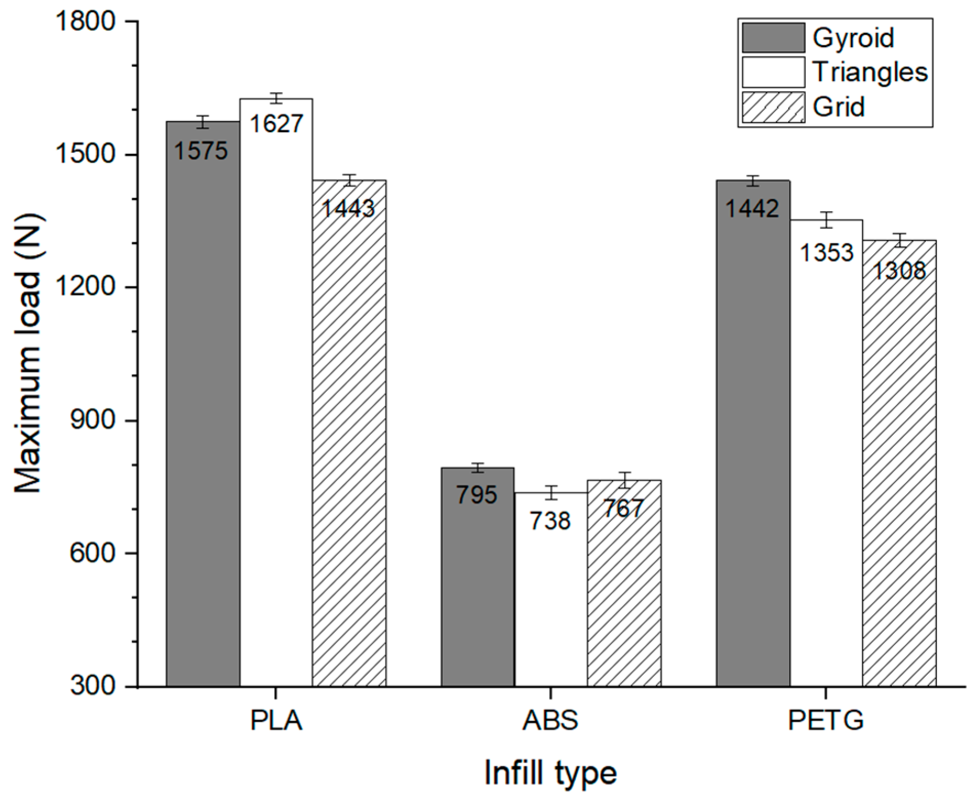
To quantify the influence of infill pattern on the mechanical strength of FFF-printed polymers, tensile tests were conducted on PLA, ABS, and PETG specimens. All samples were manufactured with consistent parameters: two walls, a printing speed of 45 mm·s−1, extrusion temperature of 210 °C, layer height of 0.20 mm, and 20% infill density. Three distinct infill patterns were tested: Gyroid, Triangular, and Grid. Across all tests, the Grid infill consistently resulted in the lowest tensile strength. The Gyroid pattern yielded the highest tensile strength for ABS and PETG, while for PLA, the Triangular infill provided superior performance. Figure 4 presents the average maximum load and standard deviation results for each configuration.
The superior performance of the Gyroid and Triangular patterns can be attributed to their isotropic path distribution and the availability of multiple load-bearing directions, which promote more uniform stress distribution throughout the structure. The continuous nature of the Gyroid infill, in particular, minimizes sharp internal corners and stress concentration zones, allowing for efficient stress transfer. Additionally, the tessellated geometry of the Triangular pattern enhances mechanical interlocking, forming a truss-like structure known for its high stiffness and load-bearing capacity. The angular configuration of the triangles supports multi-directional load transfer, outperforming the more orthogonal load paths of the Grid pattern.
Although the Gyroid infill produced the highest strength for ABS and PETG, the variability observed—particularly when compared with PLA—suggests that the effect of infill pattern is material-dependent and not universally significant. Contrary to earlier expectations based on previous studies [40], which proposed the Grid as the most mechanically robust pattern, followed by Triangular and Gyroid, the present results do not support this hierarchy. These findings emphasize the necessity of case-specific optimization rather than generalized assumptions for infill design in FFF components.

3.2. Effect of the Infill Density

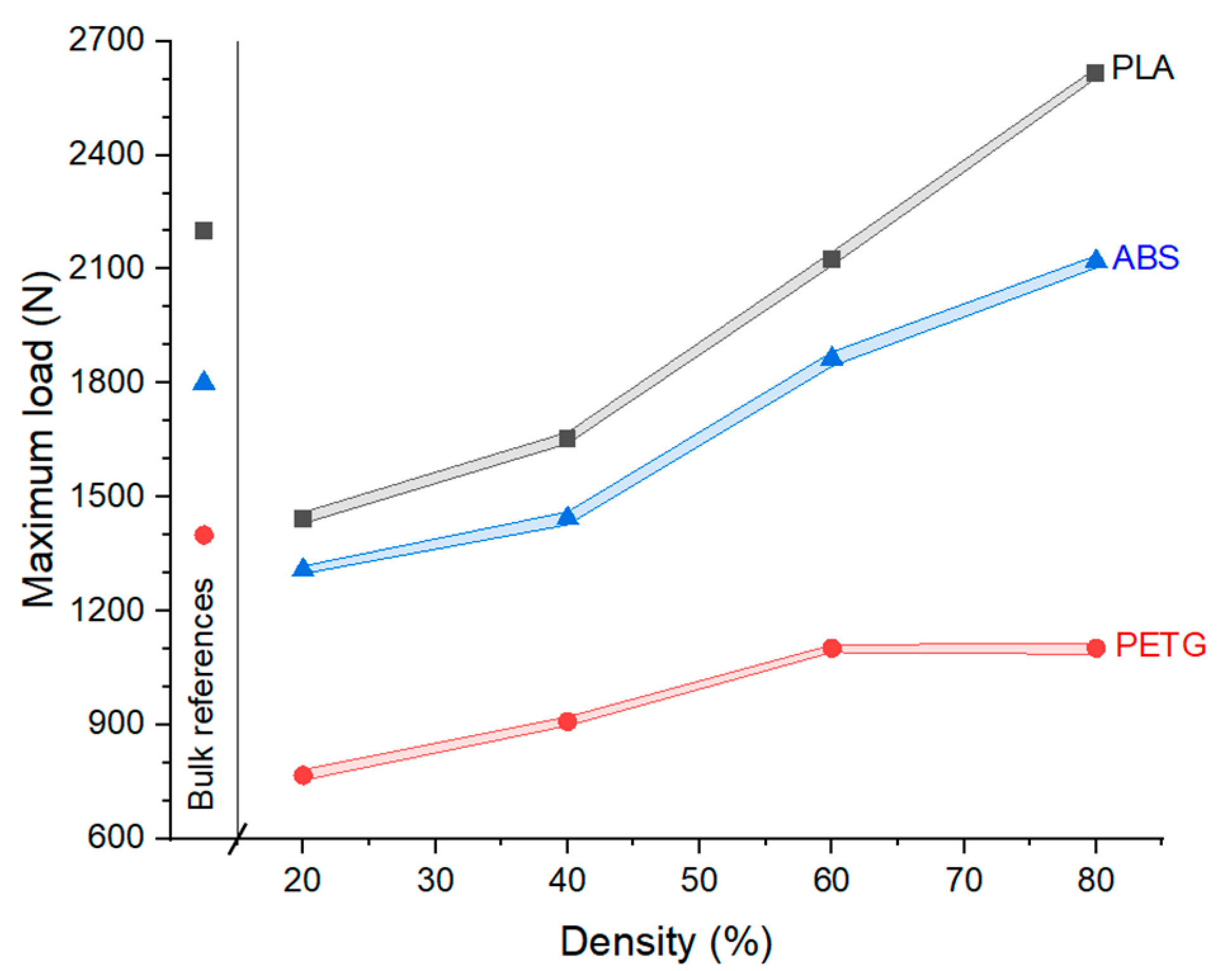
To investigate the effect of infill density on mechanical strength, tensile tests were conducted on FFF-fabricated PLA, ABS, and PETG specimens using consistent parameters: two perimeters, a printing speed of 45 mm·s−1, extrusion temperature of 210 °C, and a Grid infill pattern at densities of 20, 40, 60, and 80%. Figure 5 presents the average maximum load values and their standard deviations for each configuration.
The results revealed a general upward trend in mechanical strength with increasing infill density, most notably in PLA, which exhibited a load increase of 1173 N from 20 to 80% infill. For PETG, a nearly linear increase of 813 N was observed over the same range. In contrast, ABS displayed a plateau beyond 60% infill density, with no further improvement in strength beyond a maximum load of 1102 N.
Mechanical strengths of the printed parts approached those of their bulk counterparts as infill density increased. Specifically, the bulk-equivalent strength was achieved at approximately 63% infill for PLA and 57% for ABS, while PETG samples did not reach the bulk strength under the selected FFF parameters. The diminished improvement in ABS strength beyond 60% may be attributed to its predominantly amorphous structure, in contrast to the semi-crystalline nature of PLA and PETG [41]. These findings suggest that increasing the infill density of FFF ABS parts beyond 60% does not necessarily yield further mechanical benefits. A similar trend was reported by Sri, Karthick, and Dinesh [23], who observed a decrease in compressive strength for PETG with increasing infill density—from 95 MPa at 50% infill to 73 MPa at 90%.
From a mechanical standpoint, higher infill densities contribute to increased effective cross-sectional area, enhancing the part’s ability to resist applied loads. This increase in material volume leads to reduced local stress and delayed crack initiation, while also improving load distribution. Additionally, higher densities promote tighter path spacing and improved fusion, which enhances mechanical interlocking and interfacial adhesion between infill paths and walls, contributing to improved overall mechanical integrity.
Beyond the macroscopic tensile performance, the mechanical behavior of FFF parts is intrinsically linked to the microstructure and phase characteristics of the polymers. PLA, being a semi-crystalline polymer, exhibits mechanical performance strongly influenced by crystallinity and interlayer adhesion; higher extrusion temperatures enhance chain mobility and crystallization, improving interfacial bonding but potentially leading to thermal degradation at excessive values [33,41]. ABS, in contrast, is an amorphous polymer, where tensile strength mainly depends on entanglement density and interlayer fusion, rather than crystallinity; this explains the limited improvements observed beyond 60% infill density and the degradation at elevated temperatures [18,27,31]. PETG, with its partially crystalline nature and higher ductility, demonstrated the most stable and linear response to wall number, reflecting its ability to distribute stresses through microstructural plastic deformation [22,23,42]. In addition to maximum load, the analysis of UTS, modulus, and elongation to failure further characterizes the mechanical behavior, showing that printed parts consistently underperform compared to bulk reference values (PLA ≈ 53, ABS ≈ 40, and PETG ≈ 50 MPa [29]). These discrepancies highlight the relevance of porosity, interlayer voids, and phase transitions during processing, which remain the key microstructural mechanisms governing the final performance of FFF parts.

3.3. Effect of the Layer Height

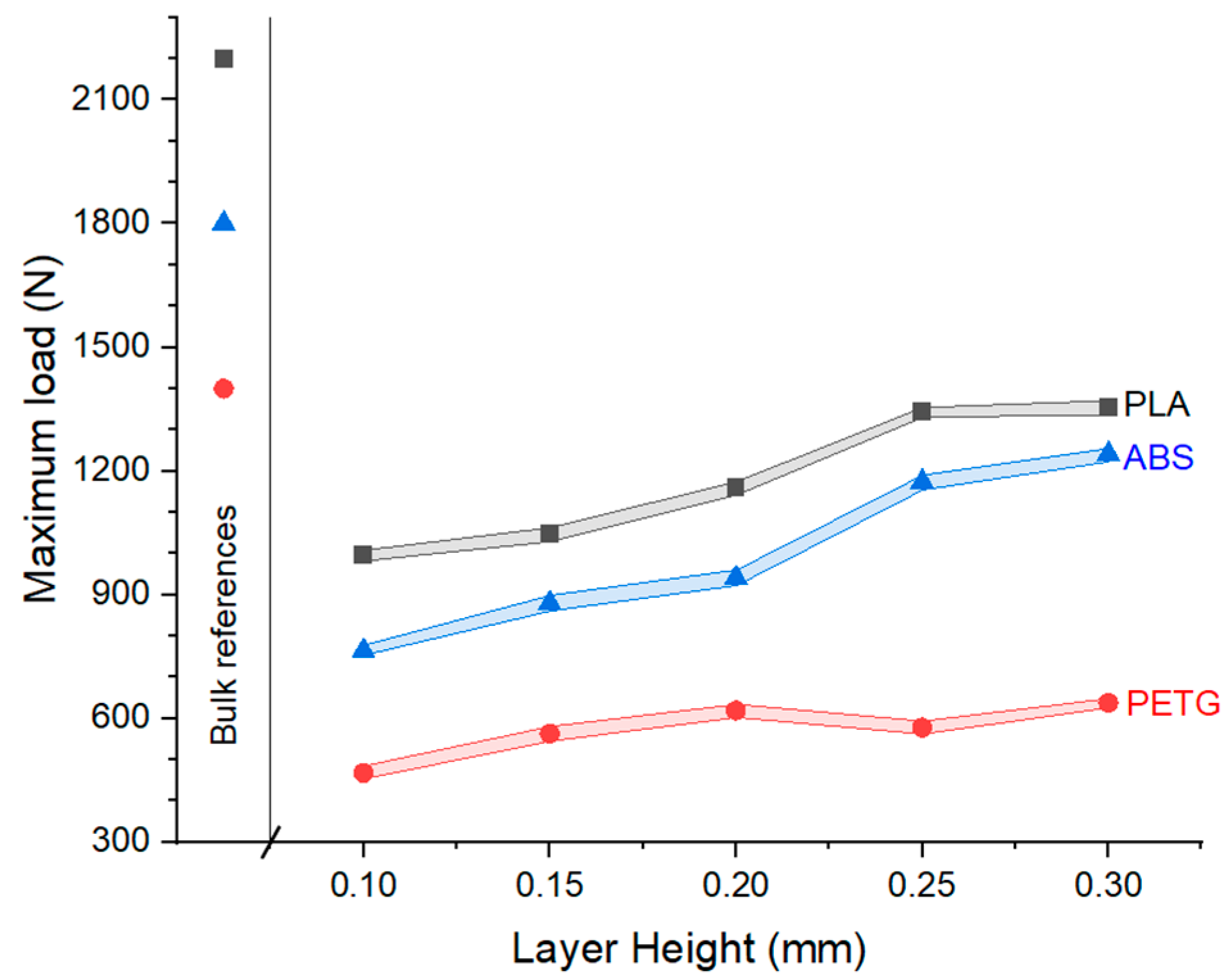
To evaluate the mechanical strength of printed parts with varying layer heights, a controlled experimental setup was established to ensure reproducibility and minimize variability. The parameters were fixed as follows: two perimeters, a printing speed of 45 mm·s−1, extrusion temperature of 210 °C, a Grid infill pattern, and an infill density of 20%. Five specimens per configuration were tested. Figure 6 presents the average maximum load and associated standard deviation for each case.
For PLA specimens, increasing the layer height from 0.10 to 0.30 mm resulted in a consistent improvement in tensile strength. The lowest strength was observed at 0.10 mm (995 N), with incremental gains at 0.15 mm (1046 N, +5%), 0.20 mm (1159 N, +16%), and 0.25 mm (1344 N, +35%). At 0.30 mm, the strength reached 1355 N, only marginally higher (+0.8%) than the previous height, indicating a plateau in mechanical benefit.
PETG exhibited a similar trend, with tensile strength increasing proportionally with layer height. Significant gains were observed, particularly at 0.25 mm, which showed a 53% improvement over the 0.10 mm configuration. Intermediate increases were recorded at 0.15 mm (+15%) and 0.20 mm (+23%), while a further increase to 0.30 mm resulted in a more modest gain of 9%.
ABS samples followed the same general pattern but demonstrated smaller absolute and relative improvements. Starting at 468 N for 0.10 mm, strength increased to 563 N (+20%) at 0.15 mm, and to 619 N (+32%) at 0.20 mm. Beyond this point, the gains were less pronounced, with values of 578 N (0.25 mm) and 638 N (0.30 mm), representing a total increase of 29% over the base configuration.
Although the mechanical strength of all three materials improved with increasing layer height, none of the printed parts achieved the reference values associated with bulk materials. This is primarily attributed to the low infill density (20%) used throughout the tests. The improved performance with higher layer heights is likely due to the reduction in interlayer bonding interfaces, which are mechanically weaker than the bulk of the printed filament. Fewer interfaces may result in reduced stress concentration points and enhanced load distribution, thereby improving overall tensile strength.

3.4. Effect of the FFF Speed

To investigate the effect of printing speed on the mechanical strength of FFF parts, the following experimental setup was used: two walls, a printing speed range of 20 to 50 mm·s−1, an extrusion temperature of 210 °C, a Grid infill pattern, and a fixed infill density of 20%. Five specimens per speed condition were printed and tested for each material. Figure 7 presents the average maximum strength and corresponding standard deviations.
The results show a general trend in which increased printing speed correlates with decreased tensile strength for all materials tested. This reduction in mechanical strength is attributed to unstable material extrusion caused by higher volumetric flow without a corresponding increase in temperature. As speed increases, the filament may be deposited at a lower actual extrusion temperature, leading to poor layer adhesion and local defects. This effect is most pronounced in PLA and PETG, while ABS exhibits a more stable response across the tested speed range.
For ABS, the highest tensile strength (1030 N) was achieved at 30 mm·s−1, representing a 5% increase over the 978 N obtained at 20 mm·s−1. Beyond 30 mm·s−1, the mechanical strength declined. PLA showed maximum strength at the lowest tested speed (1627 N at 20 mm·s−1), with progressive reductions of 5, 3, and 13% at 30, 40, and 50 mm·s−1, respectively. PETG exhibited a small initial improvement at 30 mm·s−1 (1519 N, +2%), followed by a notable drop to 1307 N at 50 mm·s−1 and a minimum of 907 N at 40 mm·s−1. None of the samples, regardless of material, reached bulk reference mechanical strength values under the low-density condition (infill of 20%).
It is concluded that higher printing speeds induce extrusion instability and reduce mechanical strength due to insufficient thermal fusion between layers. However, excessively low speeds are also detrimental. Each polymer has an optimal extrusion temperature window, and operating outside of this range can lead to material degradation. At very low speeds, the extended residence time in the heated nozzle may cause thermal degradation or early crystallization, particularly for semi-crystalline polymers such as PLA and PETG, impairing flow behavior and interlayer bonding.
For successful FFF processing, the extrusion temperature must be well above the material’s melting point to ensure proper flow, yet low enough to avoid degradation during the residence time. Therefore, selecting an optimal speed is essential to balance thermal stability and mechanical strength, minimizing defects and ensuring structural integrity of the printed parts.

3.5. Effect of the FFF Temperature

To evaluate the influence of extrusion temperature on the mechanical strength of FFF-printed components, the following setup was used: two walls, a printing speed of 45 mm·s−1, an infill density of 20%, a Grid infill pattern, and extrusion temperatures ranging from 190 to 260 °C. Five specimens per configuration were tested. Figure 8 presents the average maximum tensile strength and standard deviation for each condition.
For PLA, a consistent upward trend in tensile strength was observed with increasing extrusion temperature. At 190 °C, the tensile strength was 1658 N. A slight drop to 1594 N (−4%) at 200 °C may have resulted from minor testing variability. Above 210 °C, strength values increased steadily, peaking at 1934 N at 230 °C—a 17% improvement over the lowest temperature. This behavior aligns with the expectation that higher extrusion temperatures enhance interlayer adhesion and reduce internal voids, improving mechanical integrity.
PETG displayed a less linear response. Tensile strength rose from 1467 N at 210 °C to 1673 N at 220 °C (+14%), followed by a marginal increase to 1498 N at 230 °C. Between 240 and 260 °C, tensile strength stabilized in the range of 1616~1622 N, representing a 10% improvement over the baseline but lacking a clear trend, possibly due to polymer degradation or thermal relaxation effects at elevated temperatures.
ABS exhibited an anomalous behavior. The maximum tensile strength of 957 N was recorded at 220 °C. Beyond this point, a progressive decline was observed, with tensile strengths of 927 N at 230 °C, and decreasing further to 888, 775, and 835 N at 240, 250, and 260 °C, respectively. This unexpected trend may reflect thermal degradation of the amorphous polymer structure or poor layer bonding due to excessive fluidity at higher temperatures.
Overall, the results indicate that extrusion temperature has a material-dependent effect on the mechanical strength of FFF parts. For PLA, elevated temperatures consistently improve strength due to increasing the crystallinity and consequently the strength [27,33,41], whereas for PETG and ABS, the response did not present a processing temperature benefit because these materials do not improve the crystallinity by heat treatments and maintain the amorphous structure, or for excessive temperatures, degrade and lose strength [27,31,42]. Importantly, none of the materials reached their respective bulk reference strengths, which is consistent with the low infill density (20%) selected for this study. As shown in Figure 5, bulk-like tensile performance for PLA and ABS requires infill densities of approximately 63 and 57%, respectively.
The variability observed among the materials highlights the difficulty in defining a universal temperature strategy for optimizing FFF outcomes. The thermal behavior and rheological properties of each polymer, including melting temperature, glass transition temperature, and crystallinity, significantly influence how temperature affects interlayer fusion, void formation, and the final mechanical response.

3.6. Effect of the Number of Walls

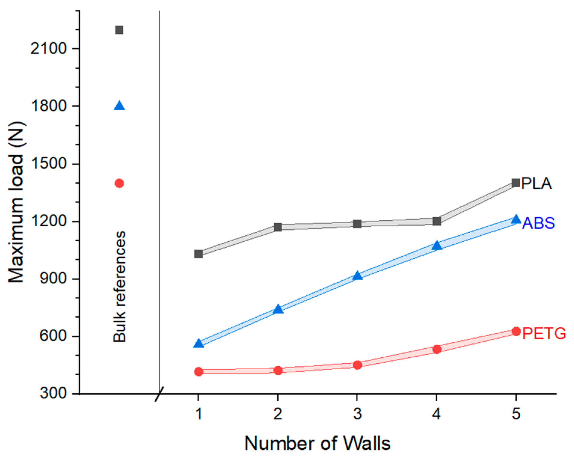
To assess the influence of the number of walls on the mechanical strength of FFF-printed specimens, tests were conducted using the following configuration: Grid infill pattern, infill density of 20%, printing speed of 45 mm·s−1, extrusion temperature of 210 °C, and variable wall counts ranging from one to five. Five specimens were tested for each configuration. The results, presented in Figure 9, show a consistent trend of increased tensile strength with higher wall counts across all three polymers evaluated: PLA, ABS, and PETG.
For PLA, specimens with a single wall exhibited an average maximum tensile load of 1030 N. Adding a second wall increased the strength to 1169 N (+13%), while three and four walls produced only modest further improvements: 1186 N (+15%) and 1201 N (+17%), respectively. The most significant increase was observed with five walls, where the strength reached 1401 N, a 36% improvement over single-wall specimens. The limited gains from three- and four-walled specimens may be attributed to process variability, such as inconsistent extrusion or weak interfacial bonding.
ABS specimens exhibited lower overall tensile strength compared to PLA but demonstrated a more progressive increase with wall count. A single-wall configuration yielded 416 N, while two walls increased the strength slightly to 422 N (+2%). With three walls, tensile strength rose to 451 N (+9%), and four walls yielded 534 N (+29%). The five-wall specimens achieved the highest resistance at 627 N, representing a 51% improvement relative to the single-wall configuration.
PETG samples displayed the most consistent and pronounced improvement with increasing wall count. The single-wall specimens withstood an average of 559 N, while tensile strength increased by 32% to 739 N with two walls. With three and four walls, the values rose to 913 N (+63%) and 1071 N (+91%), respectively. The highest performance was obtained with five walls, reaching 1207 N, a 116% increase over single-wall specimens. Among the three materials, PETG demonstrated the most linear and stable correlation between wall count and tensile strength, with reduced influence from experimental variability.
Overall, an increased number of walls resulted in improved tensile strength for all materials. However, due to the low infill density (20%) selected for this study, none of the configurations reached the bulk material reference strength. The PETG specimens, in particular, highlighted a near-linear relationship between wall count and tensile performance, suggesting that wall count significantly contributes to the structural integrity of low-density FFF parts. These findings are consistent with earlier results concerning the effects of infill density and layer height on mechanical strength, reinforcing the importance of optimizing structural parameters in FFF-printed components.

4. Conclusions

Based on the comprehensive analysis of FFF processing parameter variation for PLA, ABS, and PETG polymers, the following conclusions can be drawn:
  • The infill pattern significantly affects the tensile strength of FFF parts. Although the Grid pattern consistently yielded the lowest strength, the Gyroid and Triangular patterns improved performance for ABS and PETG, as well as PLA, respectively. However, material-dependent variability prevents a definitive selection of the most effective infill pattern.
  • Increasing the infill density enhances the mechanical strength of printed parts. PLA exhibited the most substantial increase in tensile load with higher densities, while ABS showed a plateau beyond 60% density. PETG demonstrated an almost linear relationship between density and tensile performance.
  • Increasing layer height generally improves tensile strength due to the reduction in weak interlayer interfaces. This effect is particularly notable in PLA and PETG specimens.
  • Higher printing speeds tend to reduce mechanical resistance as they introduce extrusion instability. Each material presents an optimal processing speed, beyond which performance deteriorates due to suboptimal temperature–flow dynamics.
  • Temperature had a limited and inconsistent influence on tensile strength. While PLA followed expected behavior, ABS and PETG exhibited less predictable responses, likely due to differences in polymer structure and thermal properties, such as glass transition temperature Tg.
  • An increased number of perimetral walls leads to a consistent and nearly linear improvement in tensile strength across all materials. PETG, in particular, exhibited the clearest and most reliable response, with minimal variability among trials.
The findings demonstrate that the number of walls and the infill density are the dominant factors controlling tensile strength across all three polymers, while layer height and extrusion temperature present material-dependent effects. Printing speed proved critical for preserving interlayer adhesion, particularly in PLA and PETG, highlighting the need to balance throughput and mechanical reliability.
Future research should extend this methodology toward fatigue and impact performance, as well as fracture surface and microstructural analysis, to directly correlate mechanical behavior with interfacial morphology and crystallinity. Moreover, expanding the parameter space to include build orientation, raster angle, and environmental conditioning will provide an even more complete framework. Finally, the integration of statistical modeling and machine learning could support predictive tools for optimizing additive manufacturing parameters in industrial practice.

Author Contributions

Conceptualization: S.M., J.N., I.E., M.T.B. and J.A.P.; methodology: S.M., I.E.; S.M., J.N., I.E. and M.T.B.; investigation: S.M., J.N. and I.E.; resources: M.T.B. and J.A.P.; data curation: S.M., I.E. and M.T.B.; writing—original draft preparation: S.M., J.N., I.E. and R.F.V.; writing—review and editing: S.M., J.N. and R.F.V.; project administration: M.T.B. and J.A.P.; funding acquisition: M.T.B. and J.A.P. All authors have read and agreed to the published version of the manuscript.

Funding

R.F.V. thanks the Government of Catalonia Agency for Administration of University and Research Grants, grant number 2021SGR00712.

Data Availability Statement

Data are available upon request.

Conflicts of Interest

The authors declare no conflicts of interest.

Abbreviations

The following abbreviations are used in this manuscript:
ABSAcrylonitrile Butadiene Styrene
AMAdditive Manufacturing
BJBinder Jetting
CSAMCold Spray Additive Manufacturing
DLPDigital Light Processing
FDMFused Deposition Modeling
FFFFused Filament Fabrication
MEXMaterial Extrusion
PLAPolylactic Acid
PETGModified Polyethylene Terephthalate
SLAStereolithography
SLMSelective Laser Melting
SLSSelective Laser Sintering
UTSUltimate Tensile Strength
WAAMWire Arc Additive Manufacturing

References

  1. Skylar-Scott, M.A.; Mueller, J.; Visser, C.W.; Lewis, J.A. Voxelated Soft Matter via Multimaterial Multinozzle 3D Printing. Nature 2019, 575, 330–335. [Google Scholar] [CrossRef]
  2. Vraitch, R.; Prince, M.; Souppez, J.-B.R.G. Infill Density in Additive Manufacturing and Application to the DFMA of an Iron Man Helmet. In Proceedings of the 28th International Conference on Automation and Computing (ICAC), Birmingham, UK, 30 August–1 September 2023; IEEE: Birmingham, UK, 2023; pp. 1–6. [Google Scholar]
  3. Murr, L.E. Frontiers of 3D Printing/Additive Manufacturing: From Human Organs to Aircraft Fabrication. J. Mater. Sci. Technol. 2016, 32, 987–995. [Google Scholar] [CrossRef]
  4. Palo, M.; Holländer, J.; Suominen, J.; Yliruusi, J.; Sandler, N. 3D Printed Drug Delivery Devices: Perspectives and Technical Challenges. Expert Rev. Med. Devices 2017, 14, 685–696. [Google Scholar] [CrossRef]
  5. Vaz, R.; Garfias, A.; Albaladejo, V.; Sanchez, J.; Cano, I. A Review of Advances in Cold Spray Additive Manufacturing. Coatings 2023, 13, 267. [Google Scholar] [CrossRef]
  6. Leles da Silva, M.D.; Silva, L.F.; Toralles, B.M.; Cardoso, F.A.R.; Corso, M.; Soto Herek Rezende, L.C. Building a Sustainable Future: The Role of Additive Manufacturing in Civil Construction. Case Stud. Constr. Mater. 2024, 20, e02976. [Google Scholar] [CrossRef]
  7. Compton, B.G.; Lewis, J.A. 3D-printing of Lightweight Cellular Composites. Adv. Mater. 2014, 26, 5930–5935. [Google Scholar] [CrossRef] [PubMed]
  8. Ramaux, J.; Ziegler-Devin, I.; Besserer, A.; Nouvel, C. 3D Printing of Wood Composites: State of the Art and Opportunities. Polymers 2024, 16, 2827. [Google Scholar] [CrossRef]
  9. Karayel, E.; Bozkurt, Y. Additive Manufacturing Method and Different Welding Applications. J. Mater. Res. Technol. 2020, 9, 11424–11438. [Google Scholar] [CrossRef]
  10. Saboori, A.; Aversa, A.; Marchese, G.; Biamino, S.; Lombardi, M.; Fino, P. Application of Directed Energy Deposition-Based Additive Manufacturing in Repair. Appl. Sci. 2019, 9, 3316. [Google Scholar] [CrossRef]
  11. Rasu, S. The Future of 3D Printing in Prototype Development: Minimizing Prototype Costs and Decreasing Validation Timelines. J. Eng. Appl. Sci. Technol. 2023, 5, 2–4. [Google Scholar] [CrossRef]
  12. Tan, K.; Markovych, S.; Hu, W.; Shorinov, O.; Wang, Y. Review of Manufacturing and Repair of Aircraft and Engine Parts Based on Cold Spraying Technology and Additive Manufacturing Technology. Aerosp. Tech. Technol. 2020, 3, 53–70. [Google Scholar] [CrossRef]
  13. Chaudhary, R.; Fabbri, P.; Leoni, E.; Mazzanti, F.; Akbari, R.; Antonini, C. Additive Manufacturing by Digital Light Processing: A Review. Prog. Addit. Manuf. 2023, 8, 331–351. [Google Scholar] [CrossRef]
  14. Ziaee, M.; Crane, N.B. Binder Jetting: A Review of Process, Materials, and Methods. Addit. Manuf. 2019, 28, 781–801. [Google Scholar] [CrossRef]
  15. Souza, J.; Großmann, A.; Mittelstedt, C. Micromechanical Analysis of the Effective Properties of Lattice Structures in Additive Manufacturing. Addit. Manuf. 2018, 23, 53–69. [Google Scholar] [CrossRef]
  16. Wang, S.; Ma, Y.; Deng, Z.; Zhang, K.; Dai, S. Implementation of an Elastoplastic Constitutive Model for 3D-Printed Materials Fabricated by Stereolithography. Addit. Manuf. 2020, 33, 101104. [Google Scholar] [CrossRef]
  17. Mohan, N.; Senthil, P.; Vinodh, S.; Jayanth, N. A Review on Composite Materials and Process Parameters Optimisation for the Fused Deposition Modelling Process. Virtual Phys. Prototyp. 2017, 12, 47–59. [Google Scholar] [CrossRef]
  18. Onwubolu, G.C.; Rayegani, F. Characterization and Optimization of Mechanical Properties of ABS Parts Manufactured by the Fused Deposition Modelling Process. Int. J. Manuf. Eng. 2014, 2014, 598531. [Google Scholar] [CrossRef]
  19. Ziemian, S.; Okwara, M.; Ziemian, C.W. Tensile and Fatigue Behavior of Layered Acrylonitrile Butadiene Styrene. Rapid Prototyp. J. 2015, 21, 270–278. [Google Scholar] [CrossRef]
  20. Liu, X.; Zhang, M.; Li, S.; Si, L.; Peng, J.; Hu, Y. Mechanical Property Parametric Appraisal of Fused Deposition Modeling Parts Based on the Gray Taguchi Method. Int. J. Adv. Manuf. Technol. 2017, 89, 2387–2397. [Google Scholar] [CrossRef]
  21. Domingo-Espin, M.; Borros, S.; Agullo, N.; Garcia-Granada, A.-A.; Reyes, G. Influence of Building Parameters on the Dynamic Mechanical Properties of Polycarbonate Fused Deposition Modeling Parts. 3D Print. Addit. Manuf. 2014, 1, 70–77. [Google Scholar] [CrossRef]
  22. Almonti, D.; Salvi, D.; Ucciardello, N. Optimization of Printing Parameters for Polyethylene Terephthalate Glycol Thin Honeycomb Structures with Shape-Memory Behaviors. Int. J. Adv. Manuf. Technol. 2025, 136, 4455–4469. [Google Scholar] [CrossRef]
  23. Sri, L.S.V.; Karthick, A.; Dinesh, C. Evaluation of Mechanical Properties of 3D Printed PETG and Polyamide (6) Polymers. Chem. Phys. Impact 2024, 8, 100491. [Google Scholar] [CrossRef]
  24. Silva, C.; Pais, A.I.; Caldas, G.; Gouveia, B.P.P.A.; Alves, J.L.; Belinha, J. Study on 3D Printing of Gyroid-Based Structures for Superior Structural Behaviour. Prog. Addit. Manuf. 2021, 6, 689–703. [Google Scholar] [CrossRef]
  25. Hsueh, M.-H.; Lai, C.-J.; Wang, S.-H.; Zeng, Y.-S.; Hsieh, C.-H.; Pan, C.-Y.; Huang, W.-C. Effect of Printing Parameters on the Thermal and Mechanical Properties of 3D-Printed PLA and PETG, Using Fused Deposition Modeling. Polymers 2021, 13, 1758. [Google Scholar] [CrossRef]
  26. Wirawan, W.; Firmansyah, H.I.; Adiwidodo, S.; Mustapa, M.S. Impact of Print Speed and Nozzle Temperature on Tensile Strength of 3D Printed ABS for Permanent Magnet Turbine Systems. J. Mech. Eng. Sci. Technol. 2025, 9, 90. [Google Scholar] [CrossRef]
  27. Ulkir, O.; Ertugrul, I.; Ersoy, S.; Yağımlı, B. The Effects of Printing Temperature on the Mechanical Properties of 3D-Printed Acrylonitrile Butadiene Styrene. Appl. Sci. 2024, 14, 3376. [Google Scholar] [CrossRef]
  28. Almuallim, B.; Harun, W.S.W.; Al Rikabi, I.J.; Mohammed, H.A. Thermally Conductive Polymer Nanocomposites for Filament-Based Additive Manufacturing. J. Mater. Sci. 2022, 57, 3993–4019. [Google Scholar] [CrossRef]
  29. DeLassus, P.T.; Whiteman, N.F. Physical and Mechanical Properties of Some Important Polymers. In Polymer Handbook; Brandrup, J., Immergut, E.H., Grulke, E.A., Eds.; John Wiley & Sons: New York, NY, USA, 1999; pp. 881–891. [Google Scholar]
  30. UNE-EN-ISO 527-2; Test Conditions for Moulding and Extrusion Plastics. European Committee for Standardization: Brussels, Belgium, 2012; ISBN 978 0 580 70623 3.
  31. Dawoud, M.; Taha, I.; Ebeid, S.J. Mechanical Behaviour of ABS: An Experimental Study Using FDM and Injection Moulding Techniques. J. Manuf. Process. 2016, 21, 39–45. [Google Scholar] [CrossRef]
  32. Popescu, D.; Zapciu, A.; Amza, C.; Baciu, F.; Marinescu, R. FDM Process Parameters Influence over the Mechanical Properties of Polymer Specimens: A Review. Polym. Test. 2018, 69, 157–166. [Google Scholar] [CrossRef]
  33. Yao, T.; Deng, Z.; Zhang, K.; Li, S. A Method to Predict the Ultimate Tensile Strength of 3D Printing Polylactic Acid (PLA) Materials with Different Printing Orientations. Compos. Part B Eng. 2019, 163, 393–402. [Google Scholar] [CrossRef]
  34. Gordelier, T.J.; Thies, P.R.; Turner, L.; Johanning, L. Optimising the FDM Additive Manufacturing Process to Achieve Maximum Tensile Strength: A State-of-the-Art Review. Rapid Prototyp. J. 2019, 25, 953–971. [Google Scholar] [CrossRef]
  35. Es-Said, O.S.; Foyos, J.; Noorani, R.; Mendelson, M.; Marloth, R.; Pregger, B.A. Effect of Layer Orientation on Mechanical Properties of Rapid Prototyped Samples. Mater. Manuf. Process. 2000, 15, 107–122. [Google Scholar] [CrossRef]
  36. Wang, L.; Gardner, D.J. Effect of Fused Layer Modeling (FLM) Processing Parameters on Impact Strength of Cellular Polypropylene. Polymer 2017, 113, 74–80. [Google Scholar] [CrossRef]
  37. Álvarez, K.; Lagos, R.F.; Aizpun, M. Investigating the Influence of Infill Percentage on the Mechanical Properties of Fused Deposition Modeled ABS Parts. Ing. E Investig. 2016, 36, 110–116. [Google Scholar] [CrossRef]
  38. Hanon, M.M.; Zsidai, L.; Ma, Q. Accuracy Investigation of 3D Printed PLA with Various Process Parameters and Different Colors. Mater. Today Proc. 2021, 42, 3089–3096. [Google Scholar] [CrossRef]
  39. Zou, R.; Xia, Y.; Liu, S.; Hu, P.; Hou, W.; Hu, Q.; Shan, C. Isotropic and Anisotropic Elasticity and Yielding of 3D Printed Material. Compos. Part B Eng. 2016, 99, 506–513. [Google Scholar] [CrossRef]
  40. Croccolo, D.; De Agostinis, M.; Olmi, G. Experimental Characterization and Analytical Modelling of the Mechanical Behaviour of Fused Deposition Processed Parts Made of ABS-M30. Comput. Mater. Sci. 2013, 79, 506–518. [Google Scholar] [CrossRef]
  41. Jin, Z.; Tian, Y.; Wang, J. Chemistry and Thermodynamic Properties of Lactic Acid and Lactide and Solvent Miscibility. In Poly(Lactic Acid): Synthesis, Structures, Properties, Processing, and Applications; Auras, R., Lim, L.-T., Selke, S.E.M., Tsuji, H., Eds.; Wiley: Hoboken, NJ, USA, 2010; pp. 19–25. ISBN 9780470293669. [Google Scholar]
  42. Özen, A.; Abali, B.E.; Völlmecke, C.; Gerstel, J.; Auhl, D. Exploring the Role of Manufacturing Parameters on Microstructure and Mechanical Properties in Fused Deposition Modeling (FDM) Using PETG. Appl. Compos. Mater. 2021, 28, 1799–1828. [Google Scholar] [CrossRef]
Figure 1. Infill type: (a) Gyroid, (b) triangular, and (c) grid.
Processes 13 02733 g001
Figure 2. Infill density: (a) 20, (b) 40, and (c) 60%.
Processes 13 02733 g002
Figure 3. Tensile testing: (a) sample draw and (b) FFF PLA-made sample with 20% density Triangular infill. Unit: mm.
Processes 13 02733 g003
Figure 4. Effect of the infill type on the samples’ mechanical strength.
Processes 13 02733 g004
Figure 5. Effect of the infill density on the samples’ mechanical strength.
Processes 13 02733 g005
Figure 6. Effect of layer height on the samples’ mechanical strength.
Processes 13 02733 g006
Figure 7. Effect of the FFF speed on the samples’ mechanical strength.
Processes 13 02733 g007
Figure 8. Effect of FFF temperature on the samples’ mechanical strength.
Processes 13 02733 g008
Figure 9. Effect of the number of walls on the samples’ mechanical strength.
Processes 13 02733 g009
Table 1. FFF temperatures tested for PLA, ABS, and PETG.
Temperature (°C)PLAABSPETG
190x
200x
210xxx
220xxx
230xxx
240 xx
250 xx
260 xx
Disclaimer/Publisher’s Note: The statements, opinions and data contained in all publications are solely those of the individual author(s) and contributor(s) and not of MDPI and/or the editor(s). MDPI and/or the editor(s) disclaim responsibility for any injury to people or property resulting from any ideas, methods, instructions or products referred to in the content.