Article

Mechanical Behavior and Stress Mechanism of Roof Cutting Gob-Side Entry Retaining in Medium-Thick Coal Seams

1
Shanxi Coking Coal Huozhou Coal and Electricity Dianping Coal Mine, Lvliang 033199, China
2
College of Environment and Ecology, Taiyuan University of Technology, Taiyuan 030024, China
*
Author to whom correspondence should be addressed.
Processes 2025, 13(8), 2649; https://doi.org/10.3390/pr13082649
Submission received: 20 July 2025 / Revised: 11 August 2025 / Accepted: 19 August 2025 / Published: 21 August 2025
(This article belongs to the Section Process Control and Monitoring)

Abstract

In response to the complex challenges posed by gob-side entry retaining in medium-thick coal seams—specifically, severe stress concentrations and unstable surrounding rock under composite roof structures—this study presents a comprehensive field–numerical investigation centered on the 5-200 working face of the Dianping Coal Mine, China. A three-dimensional coupled stress–displacement model was developed using FLAC3D to systematically evaluate the mechanical behavior of surrounding rock under varying roof cutting configurations. The parametric study considered roof cutting heights of 6 m, 8 m, and 10 m and cutting angles of 0°, 15°, and 25°, respectively. The results indicate that a roof cutting height of 8 m combined with a 15° inclination provides optimal stress redistribution: the high-stress zone within the coal rib is displaced 2–3 m deeper into the coal body, and roof subsidence is reduced from 2500 mm (no cutting) to approximately 200–300 mm. Field measurements corroborate these findings, showing that on the return airway side with roof cutting, initial and periodic weighting intervals increased by 4.0 m and 5.5 m, respectively, while support resistance was reduced by over 12%. These changes suggest a delayed main roof collapse and decreased dynamic loading on supports, facilitating safer roadway retention. Furthermore, surface monitoring reveals that roof cutting significantly suppresses mining-induced ground deformation. Compared to conventional longwall mining at the adjacent 5-210 face, the roof cutting approach at 5-200 resulted in notably narrower (0.05–0.2 m) and shallower (0.1–0.4 m) surface cracks, reflecting effective attenuation of stress transmission through the overburden. Taken together, the proposed roof cutting and pressure relief strategy enables both stress decoupling and energy dissipation in the overlying strata, while enhancing roadway stability, reducing support demand, and mitigating surface environmental impact. This work provides quantitative validation and engineering guidance for intelligent and low-impact coal mining practices in high-stress, geologically complex settings.

1. Introduction

China’s energy landscape is fundamentally shaped by a structural imbalance—characterized as “coal-abundant, oil-scarce, and gas-deficient”—a reality that remains persistent despite national efforts toward diversification and decarbonization [1,2,3,4]. While the proportion of renewable energy has steadily increased, coal continues to underpin the country’s energy security. As of 2023, coal contributed 55.3% to the total energy consumption of 5.72 billion tons of standard coal equivalent, maintaining its central role in industrial processes such as power generation, metallurgy, and chemical production [5,6,7,8,9,10].
With the depletion of shallow coal resources in eastern China, the mining frontier has shifted westward, where large-scale coalfields—especially Jurassic basins dominated by medium-thick seams—offer favorable geological conditions for mechanized extraction [11,12,13,14,15,16,17,18,19,20]. However, this transition exposes new challenges in safety, efficiency, and sustainability. The conventional “121” mining layout—comprising two roadways and one coal pillar per working face—remains prevalent in many operations, despite its well-documented drawbacks: low recovery rates, elevated excavation volumes, and severe stress concentrations that compromise roadway stability [21,22,23].
The implications of such mining methods are not merely economic. According to cumulative statistics, coal mining in China has resulted in over 260,000 fatalities since the industry’s expansion, with roadway accidents comprising 91.25% of all incidents. Notably, around 90% of these occurred during gob-side entry operations, highlighting a critical need for safer roadway retention strategies [24,25].
In this context, the gob-side entry retaining without coal pillar (GERWCP) technology has gained traction as an innovative approach to pillarless mining [26,27,28]. By eliminating the need for solid coal pillars and reducing roadway excavation, GERWCP improves both resource recovery and roadway stability. Compared with the traditional “121” mining layout, GERWCP offers significant advantages: it eliminates the need for solid coal pillars, thereby increasing resource recovery rates by approximately 5–15%; reduces roadway excavation by about 20–30%, which lowers labor and material costs; mitigates stress concentration around roadways, enhancing overall stability and safety; and delivers substantial economic benefits by avoiding coal losses exceeding 400 million tons and preventing related economic losses of over RMB 200 billion annually. In addition, GERWCP supports green mining practices by reducing land subsidence and environmental disturbance [24,25,29,30].
Despite its promise, the widespread adoption of GERWCP is still hampered by technical challenges, particularly under complex geological conditions such as medium-thick coal seams capped with composite roof structures [30,31]. In modern mechanized mines, the increasing power and scale of equipment necessitate long-distance reserved roadways, often exceeding 1000 m and in some cases extending to 2000–3000 m [31,32]. Under these circumstances, the surrounding rock endures prolonged dynamic stress, leading to progressive deformation, section shrinkage, and loss of functional integrity. Existing research has primarily focused on thin or thick seams with simpler roof structures, leaving a notable gap in understanding the deformation and stability control of GERWCP under medium-thick seam conditions with layered composite roofs. This presents a key technical bottleneck to achieving safe, continuous, and fully pillarless mining in deep or complex strata.
To address this, the present study investigates the 5-200 working face of Dianping Coal Mine in Shanxi Province—a representative site of medium-thick coal seams with a layered roof structure. The research focuses on the mechanical behavior of overburden and stress evolution associated with gob-side entry retaining through roof cutting and pressure relief techniques. By integrating numerical simulation and field monitoring, this study aims to elucidate the deformation mechanisms and spatial stability of the retained roadway. The findings are expected to provide theoretical insights and practical guidance for advancing safe, efficient, and green mining technologies in geologically complex coalfields.

2. Materials and Methods

2.1. Study Area

The 5-200 working face is situated within the Liliu mining district of Shanxi Province, at a burial depth ranging from 225 m to 360 m (Figure 1). The working face elevation spans from +822 m to +892 m, while the surface elevation lies between +1085 m and +1215 m, reflecting a moderate overburden typical of mid-depth coal seams. The panel extends 220 m along the dip direction and 1088 m along the strike and employs a longwall mining method with full caving for roof control. The geological dip of the No. 5 coal seam, the primary target for extraction, ranges from 2° to 8°, and exhibits a relatively stable average thickness of 3.1 m, representing a characteristic medium-thick seam configuration.
Petrographic analysis indicates that the No. 5 seam contains 2–3 interbedded sandy mudstone layers, collectively contributing a thickness of approximately 0.25–0.35 m. The coal itself is of high quality, with a black color, prominent vitreous luster, and moderate toughness. Across the panel, coal seam thickness remains relatively consistent, varying between 2.8 m and 3.4 m in both main and auxiliary entries. Spatially, the seam thickness follows a discernible pattern of initial increase, subsequent decrease, and eventual stabilization, which is significant for predicting stress redistribution during extraction.
From a hydrogeological perspective, the previously mined overlying No. 3 and No. 5 seams have not contributed to water accumulation within the goaf areas, due to the effective elevation gradient and well-planned drainage system embedded in the roadway design. This reduces the risk of water-induced instability.
A notable complexity arises from the roof lithology, which exhibits pronounced variability along the strike. Stratigraphic data derived from borehole cores and roof cross-sectional mapping indicate the existence of three dominant structural roof types: (1) soft-over-hard structures, (2) fractured composite structures, and (3) stable composite structures. These structural classifications exhibit distinct lithological compositions—principally alternating sandy mudstone, medium-grained sandstone, and localized limestone—and have direct implications for roadway deformation behavior, support design strategies, and stress concentration mechanisms during mining. The spatial heterogeneity in roof conditions across the panel adds an additional layer of complexity to entry retaining and surrounding rock control, warranting careful integration of localized support schemes and stress relief techniques.
At the regional scale, the Dianping Coal Mine lies in the central-northern part of the Hedong Coalfield, within the Lishi detailed exploration area. The Hedong Coalfield occupies the southeastern flank of the Lüliang Mountains along a north–south structural belt on the east bank of the Yellow River, corresponding to the “north–south tectonic belt on both sides of the Yellow River”. Overall, the coalfield forms a westward-dipping monocline, representing part of the western limb of the Lüliang composite anticline. Superimposed on this monocline are secondary folds and faults, with the largest structures in the mining area being the Lishi–Zhongyang syncline, Wangjiahuai anticline, and Sanjiao–Liulin monocline. Major faults, such as the TuanShuiTou Fault, disrupt seam continuity in certain areas. The coal-bearing strata mainly comprise the Upper Carboniferous Taiyuan Formation (C3t) and Lower Permian Shanxi Formation (P1s), consisting of gray-white sandstones of various grain sizes, gray to black sandy mudstones, mudstones, limestones, and multiple coal seams. The Taiyuan Formation contains 8 coal seams (Nos. 5–12), among which No. 9 and No. 10 are regionally stable and minable, while the Shanxi Formation also contains 8 seams (Nos. 01–5), of which Nos. 3 and 5 are the most continuous and economically significant. This regional structural and stratigraphic framework exerts primary control over seam occurrence, thickness stability, and mining conditions, and provides a broader geological context for evaluating the generalizability of the study results.

2.2. The Principle of the Gob-Side Entry Retaining by Roof Cutting

Building upon the theoretical framework of the short cantilever beam model for directional roof fracturing [30,31,33], the gob-side entry retaining technique via pre-fractured roof control is typically implemented through a progressive, three-stage engineering sequence: (1) preparatory anchorage and directional weakening, (2) dynamic stress response regulation during extraction, and (3) post-collapse stabilization and functional roadway formation.
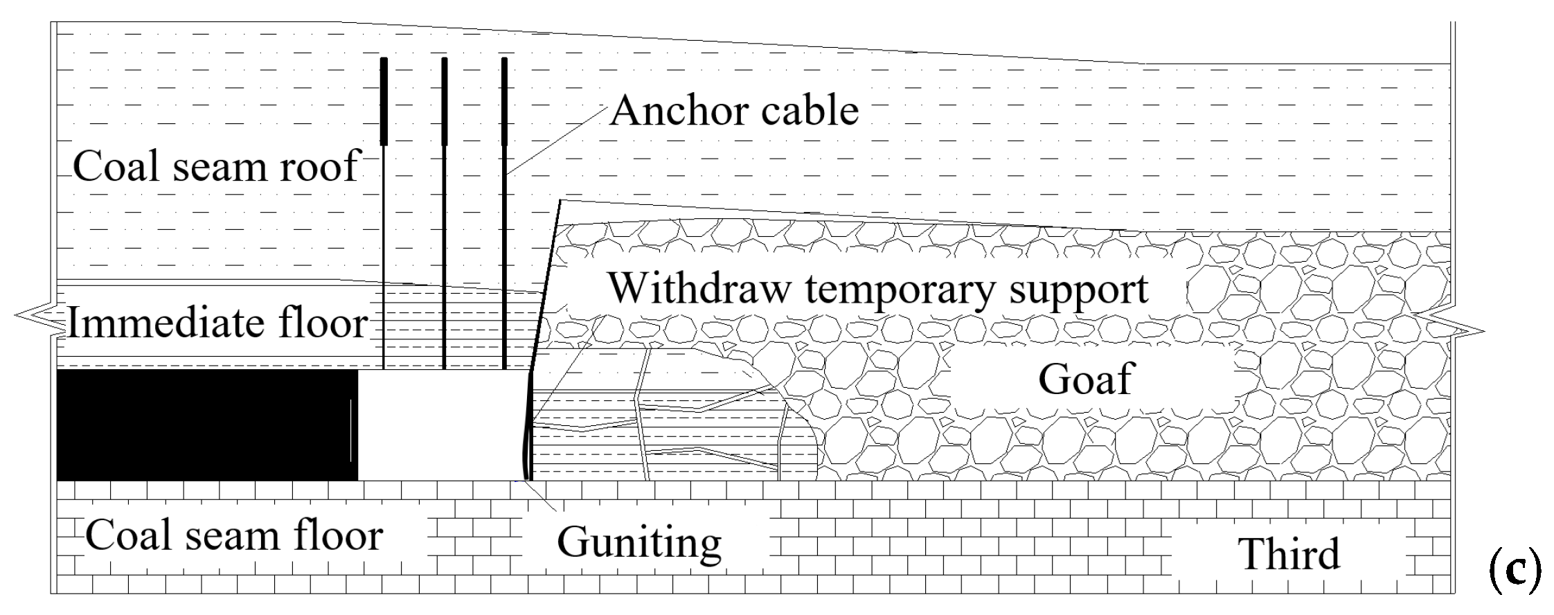
In the first phase, to accommodate both flexibility and durability under anticipated high deformation, a system of constant-resistance, large elongation anchor cables is deployed along both the designed roadway alignment and the goaf-adjacent boundary (Figure 2a). These support components are installed in conjunction with the precise positioning of boreholes for controlled energy-focusing blasting, typically executed ahead of the advancing face. The bi-directional initiation of explosive charges along the intended roof cutting trajectory induces a predetermined failure plane within the overlying strata, creating a localized damage zone that facilitates subsequent deformation control.
As the working face enters the second stage, overburden materials located on the goaf side undergo progressive subsidence and shearing along the artificial discontinuity, driven by both gravitational loading and dynamic stress redistribution induced by coal extraction. To counteract the evolving lateral pressure exerted by caved gangue, a combination of rigid structural components—such as I-section steel beams or U-type supports—and yieldable hydraulic props is arranged in the vicinity of the roof cut boundary. In parallel, temporary roof stability across the retained roadway is ensured using densely spaced high-strength supports or multi-row prop systems adapted to the evolving stress field.
The final phase commences once sufficient compaction has occurred within the goaf region. Temporary internal supports are removed in a staged manner, after which the formed roadside gangue wall is treated using sealing layers to enhance gas isolation and restrict air leakage from the goaf. This integrated construction-control process results in a structurally stable, ventilation-compatible gob-side entry capable of supporting subsequent longwall panels, effectively eliminating the need for coal pillar retention and enhancing both recovery efficiency and roadway continuity.

2.3. Numerical Modeling Framework

During the implementation of automatic roadway formation via roof cutting and pressure relief, dynamic adjustments to the overlying strata frequently trigger pronounced deformation responses in the adjacent rock mass. In particular, the surrounding rock near the excavation perimeter often exhibits yielding behavior or transitions into a plastic flow regime, while the more distant coal and rock bodies generally remain within the elastic range due to lower stress perturbation.
To simulate this complex mechanical response, FLAC3D 3.0 was adopted in this study owing to its capacity to capture the continuous deformation process of geomaterials undergoing elasto-plastic transition and post-peak softening [34,35]. The software operates based on an explicit finite difference scheme to solve the governing equations of motion and incorporates a flexible mixed-element discretization framework. This approach is especially effective in modeling strain localization, progressive failure, and large deformation phenomena, making it particularly suitable for analyzing the mechanical evolution of roadway surroundings under non-uniform and stress-redistributed environments induced by roof cutting.
By leveraging these capabilities, FLAC3D enables a high-fidelity reconstruction of the spatial and temporal evolution of stress, strain, and displacement in the rock mass during the sequential process of roadway formation. The numerical simulation framework thus offers a valuable platform for exploring deformation patterns and evaluating the effectiveness of surrounding rock control measures under pressure relief conditions, aligning precisely with the engineering objectives of this research.
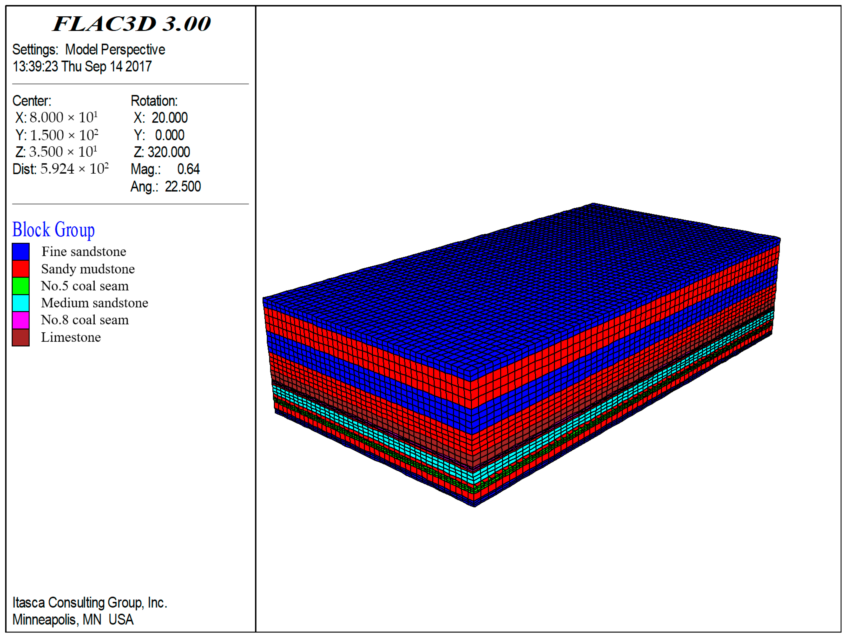
In consideration of both site-specific geological features and the need to maintain computational tractability, the widely validated Mohr–Coulomb failure criterion was selected to characterize the mechanical behavior of the surrounding strata in the return airway of the 5-200 working face at Dianping Coal Mine. The constructed numerical domain measured 200 m (length) × 350 m (width) × 85 m (height), with roadway excavation dimensions modeled as 5 m (height) × 320 m (length) × 3 m (width), and the working face excavation as 100 m × 200 m × 3 m. The average burial depth of the roadway was approximately 320 m, and the roadway alignment followed the immediate roof and floor of the No. 5 coal seam.
Stratigraphically, the floor beneath the seam consists of 3.3 m of sandy mudstone overlying 2.8 m of fine sandstone, while the roof is composed (from bottom to top) of 2.4 m of No. 5 coal, capped by 0.7 m of sandy mudstone, 6.1 m of medium-grained sandstone, 2.1 m of sandy mudstone, and an uppermost 6.0 m thick limestone layer. These lithological units exhibit considerable variation in mechanical properties, which were incorporated into the numerical model, as shown in Table 1, while the overall model geometry and boundary configuration are illustrated in Figure 3.

3. Results and Discussion

3.1. Evolution of Mine Pressure During Roof Cutting and Pressure Relief Entry Retaining Subsection

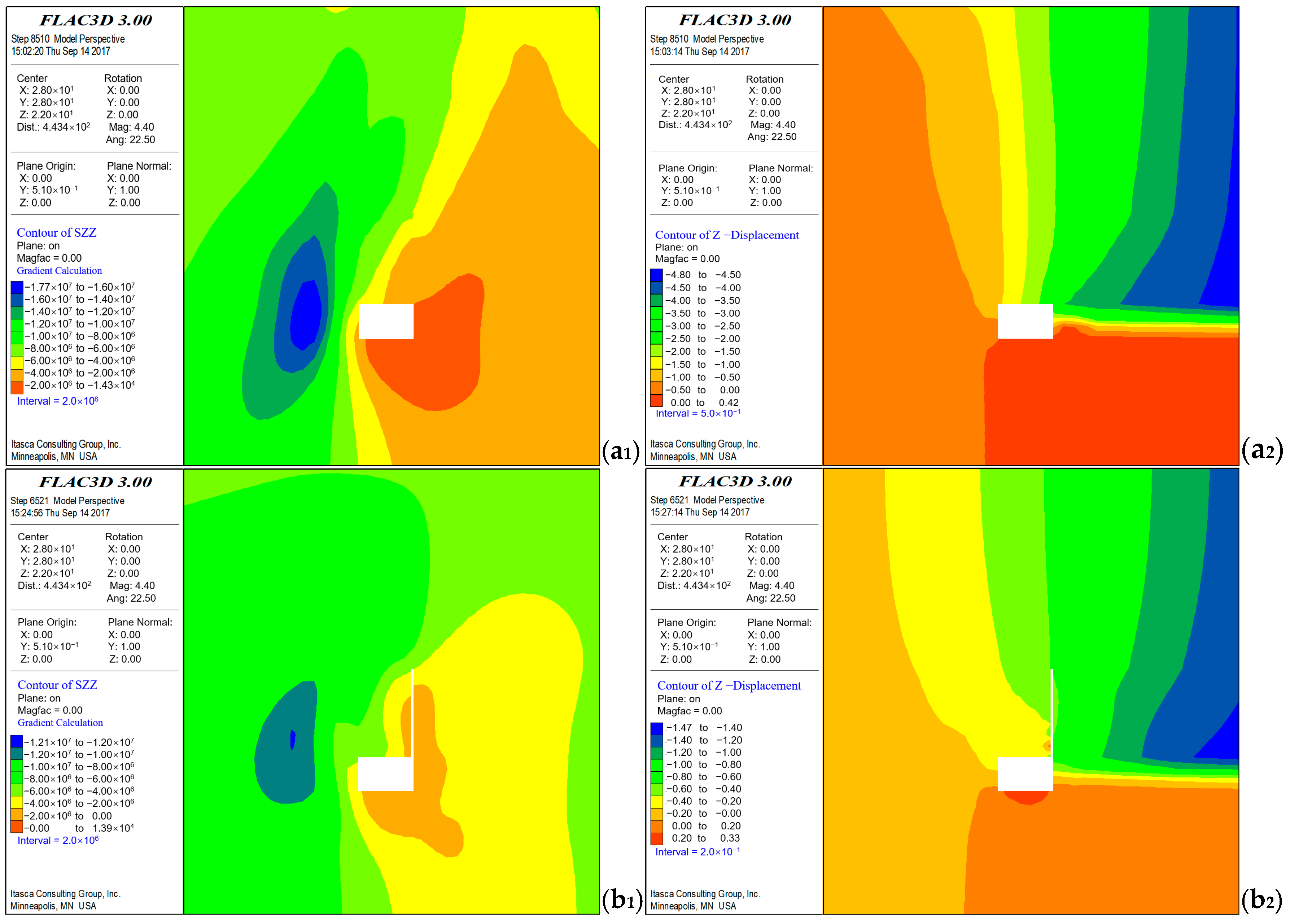
To investigate the stress redistribution and deformation mechanisms associated with roof cutting and pressure relief gob-side entry retaining, a comparative numerical analysis was performed using FLAC3D. Simulations were conducted under two scenarios: conventional excavation without roof cutting and roadway formation incorporating roof cutting techniques. The corresponding mechanical response is illustrated in Figure 4.
In the absence of roof cutting, significant stress accumulation occurs within the coal pillar adjacent to the goaf side roadway. The peak vertical stress reaches 17.8 MPa, and the concentration zone lies only 3.0 m from the roadway edge. This proximity increases the likelihood of coal rib spalling and localized failure of the surrounding rock. Moreover, elevated vertical stresses—up to 10 MPa—extend over 15 m above the roadway and face, creating sustained stress fields that jeopardize structural stability. Roof deformation contours further reveal substantial vertical displacement on the goaf side (approximately 2500 mm), resulting from roof collapse and asymmetric overburden movement, while the coal side remains relatively undeformed, exacerbating instability through stress imbalance.
In contrast, when roof cutting is applied, the surrounding rock exhibits significantly improved mechanical response. The stress concentration zone narrows, with the peak stress reduced to 12.1 MPa, and the distance from the roadway edge increases to 6.0 m, mitigating direct stress impact on the entry. Additionally, a clear pressure relief zone forms above the roadway, where vertical stress decreases to around 8 MPa. Roof settlement is drastically reduced to 250 mm, indicating effective isolation of stress transfer from the goaf to the roadway. These results affirm the role of roof cutting in moderating stress transmission and enhancing roadway stability.

3.2. Impact of Roof Cutting Height on Stress Redistribution and Deformation Behavior

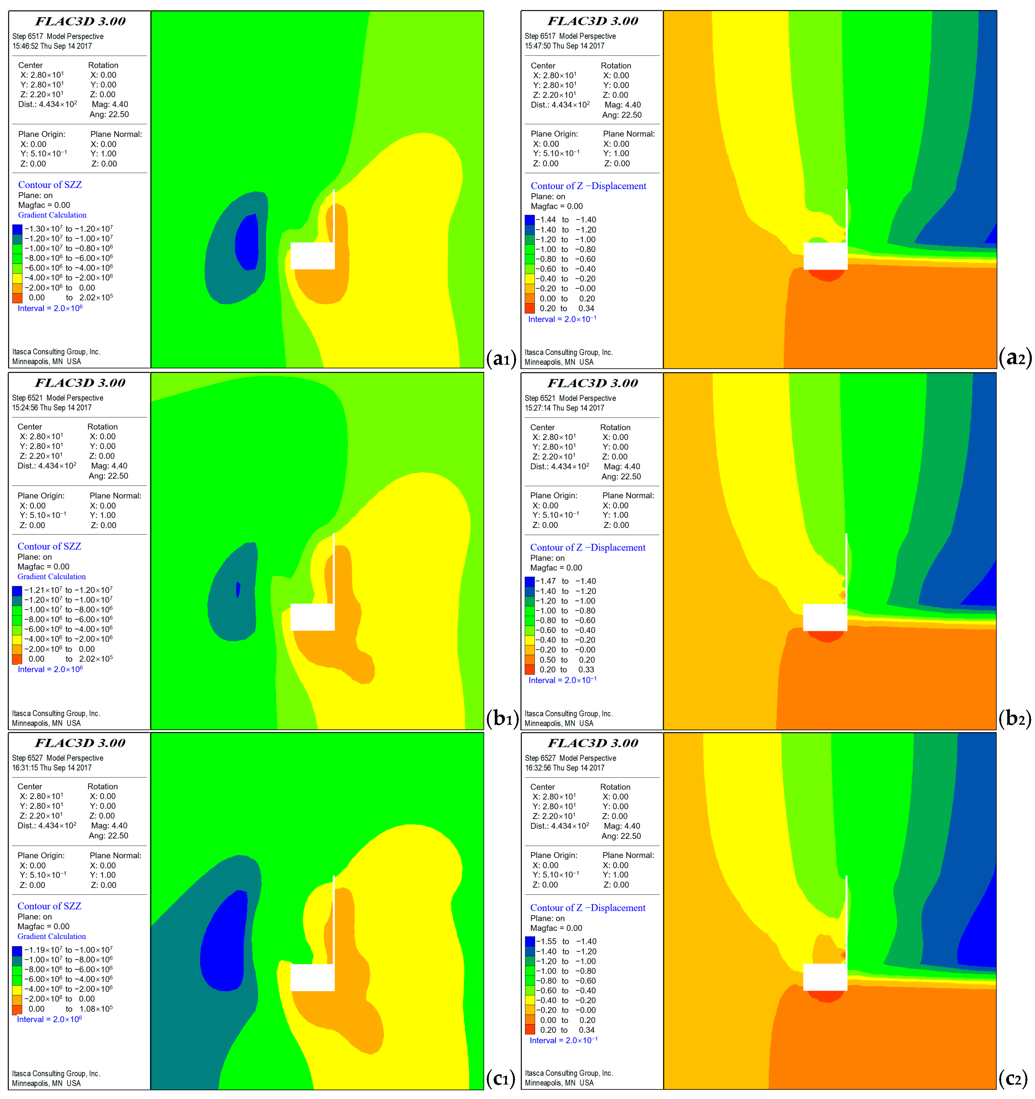
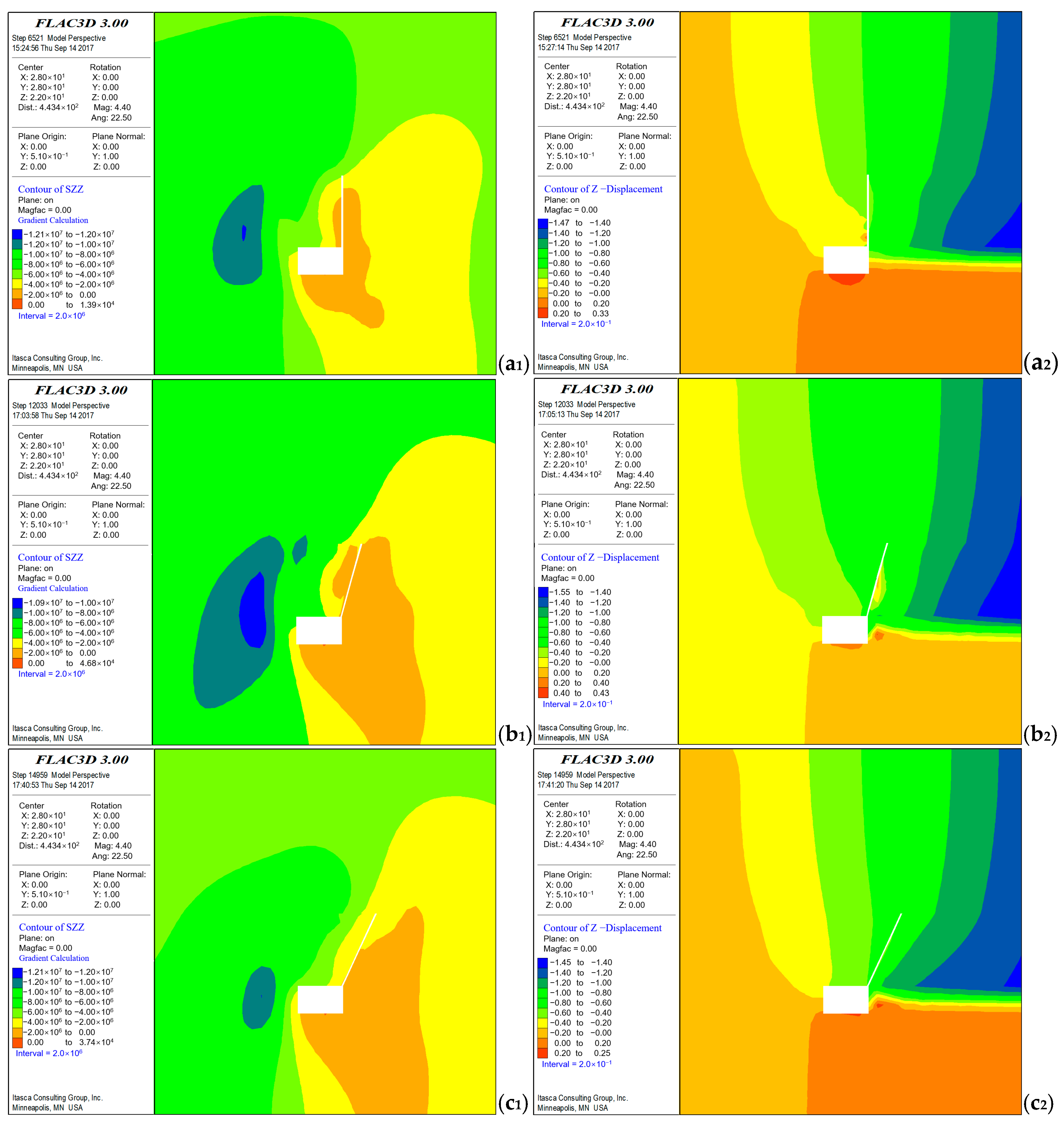
To assess how roof cutting height influences stress field evolution and deformation behavior during gob-side entry retaining, three numerical models were developed with roof cutting heights of 6 m, 8 m, and 10 m, respectively. Stress and displacement fields following excavation are depicted in Figure 5.
Simulation results demonstrate that roof cutting height significantly affects the intensity and spatial positioning of stress concentrations. At 6 m, the stress concentration zone is located 4 m from the roadway, with a peak vertical stress of 13.0 MPa, posing a high risk of rib instability. Increasing the height to 8 m shifts the peak stress zone to 6 m from the roadway and reduces the peak to 12.1 MPa, improving stability. At 10 m, the stress zone extends to 7 m, with further stress reduction to 11.9 MPa, but the marginal improvement beyond 8 m becomes negligible.
Simultaneously, the development of a pressure relief zone above the roadway is more evident at greater cutting heights. At 6 m, vertical stress above the roadway remains high (approx. 12 MPa), indicating limited unloading. This reduces to 10 MPa and 8 MPa for 8 m and 10 m heights, respectively. In terms of roof deformation, a strong inverse relationship is observed: maximum displacement decreases from 500 mm (6 m) to 250 mm (8 m) and then to 200 mm (10 m). However, the diminishing improvement at 10 m, coupled with increased construction complexity and cost, suggests that 8 m is an optimal compromise between performance and efficiency.

3.3. Effect of Roof Cutting Angle on Mechanical Response of Roadway

To further explore how the inclination angle of the roof cutting plane influences stress distribution and deformation, three cutting angles—0°, 15°, and 25°—were simulated. The resulting stress contours and displacement fields are presented in Figure 6.
At a cutting angle of 0°, the peak stress reaches 12.1 MPa, situated 6 m from the coal rib. A moderate pressure relief zone forms above the roadway, with vertical stress tapering to 10 MPa. The roof exhibits limited deformation (250 mm), indicating a relatively effective separation from the goaf. When the angle is increased to 15°, the peak vertical stress decreases to 10.9 MPa, and the stress relief zone expands, with vertical stress reducing to 8 MPa. Roof displacement slightly increases to 300 mm, primarily on the goaf side, suggesting enhanced caving without compromising roof integrity.
However, at 25°, performance deteriorates. The stress concentration shifts closer to the coal rib (4 m), and peak stress rebounds to 12.0 MPa. The pressure relief effect weakens, and the maximum roof displacement surges to 500 mm, indicating significant structural deterioration. These results suggest that moderate cutting angles improve stress redistribution and promote stable caving, but excessive angles increase the cantilever span of the overlying beam, undermining structural stability via a short-arm beam effect.
Thus, the roof cutting angle exerts a dual influence: moderate angles (15°) facilitate caving and effective stress redistribution, while excessive angles (25°) compromise mechanical performance. Considering deformation control, stress relief, and construction feasibility, a cutting angle of 15° represents an optimal balance.

3.4. Spatial Stress Distribution During Actual Roof Cutting Mining Progression

To refine the understanding of in situ stress evolution during roadway formation under roof cutting conditions, a detailed analysis was conducted based on three-dimensional stress field monitoring. As mining advances, the collapse and disordered compaction of gangue in the goaf induce complex overburden bending and subsidence, making stress evaluation on fixed horizontal planes challenging.
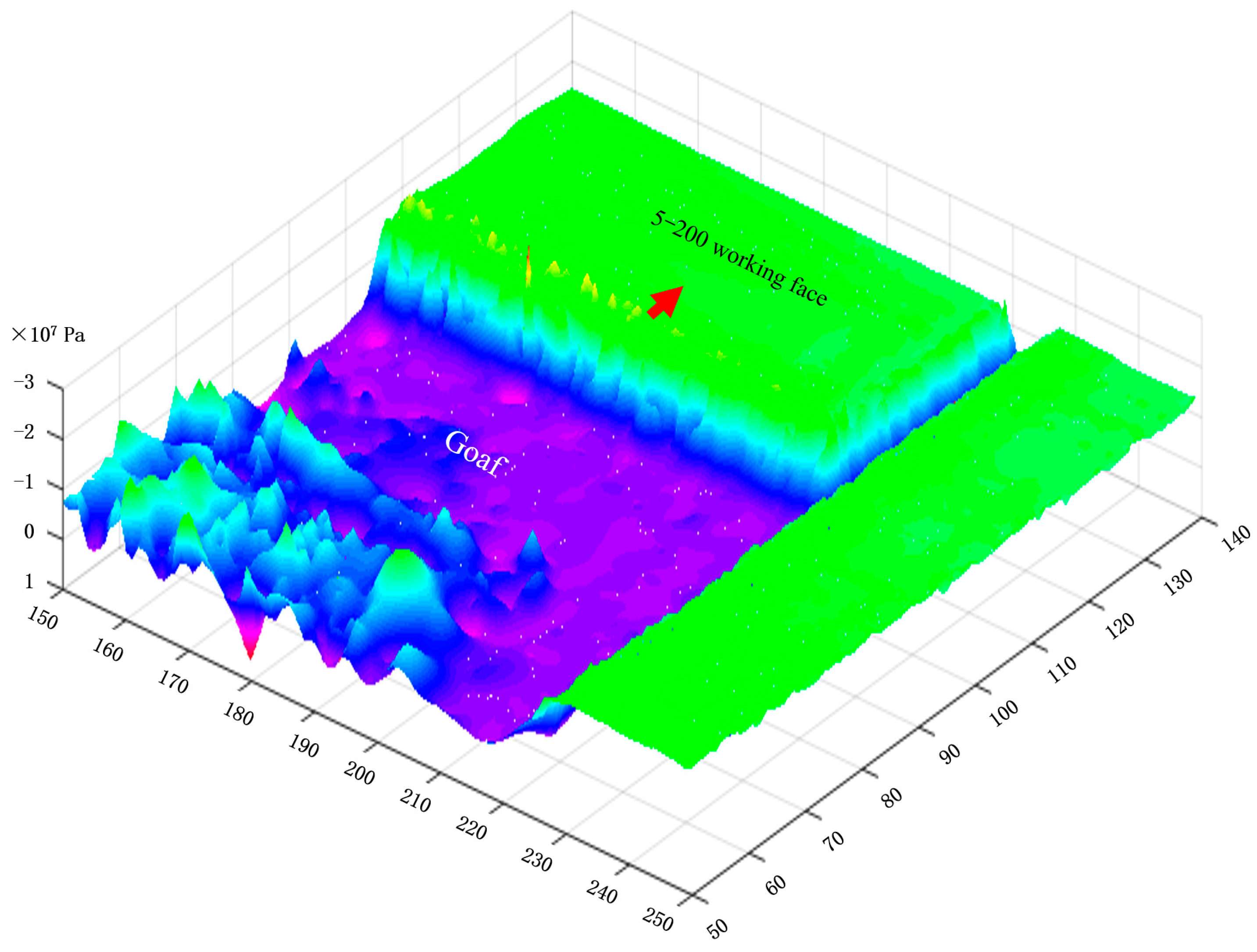
To address this, vertical stress was monitored on a plane located 0.5 m below the roadway roof after the working face advanced 105 m. The three-dimensional vertical stress field is illustrated in Figure 7, with the following key observations:
(1)
The stress field exhibits a distinct gradient. While the roadway lies in a low-stress zone, significant stress recovery occurs in the goaf, especially near the coal mass. Stress concentrations persist near the face, reflecting strong spatial heterogeneity in stress redistribution.
(2)
A pronounced stress resurgence initiates 15 m behind the face, intensifying at 25 m, particularly in central regions. Stress magnitude attenuates toward the roadway, confirming that mining-induced disturbance weakens spatially with distance.
(3)
The roadway constructed via roof cutting remains in a stable, low-stress environment. Minimal deflection of the gangue wall and weak stress recovery ensure favorable long-term stability of the entry.
(4)
Peak vertical stress ahead of the face gradually reduces from the center outward and diminishes further with increased distance. On the roadway side, a similar trend is observed, confirming stress attenuation patterns.
These findings substantiate and extend the numerical simulation results, offering valuable insight into the dynamic redistribution of stress in roof cutting gob-side entry retaining systems. They reinforce the validity of the proposed design parameters and provide robust theoretical support for optimizing roadway support and layout under complex geological conditions.

4. Engineering Applications and Effectiveness

4.1. Stress Response and Pressure Evolution Under RCGSER

Analysis of field monitoring data (Table 2 and Table 3) reveals a marked extension in both the initial and periodic weighting intervals on the gob-side with roof cutting. Specifically, the initial fracture span increased by approximately 4 m, while the periodic interval extended by about 5.5 m relative to the intake-airway side without intervention. These results highlight the substantial influence of roof cutting on the mechanical behavior and load transfer mechanisms at the longwall face.
The modification of roof mechanics stems from the pre-weakened condition induced by directional blasting along the designated roof cutting line. This process facilitates a more prompt and controlled collapse of the immediate roof, generating finer rock fragments with elevated bulking coefficients. Consequently, the void space within the goaf is efficiently filled, restricting the rotation and downward movement of the main roof. The constrained rotation reduces shear displacement and delays the onset of significant structural breakage, thus extending the overall caving interval.
Despite the increased roof span before collapse, hydraulic support data show a significant reduction in the average working resistance on the RCGSER-treated side. This reduction reflects the attenuation of load transfer intensity due to improved caving and compaction behavior within the goaf. The fragmented gangue provides immediate resistance to vertical movement, buffering the transmission of overburden pressure to the support system. In essence, the RCGSER method not only stabilizes the strata movement but also decreases peak support loads, offering a robust mechanical basis for the refinement of roadway positioning and support design under complex geological conditions.
It should be noted that while the general trends in hydraulic support resistance and weighting interval from field measurements match the numerical simulation results, minor deviations in absolute values are observed. These can be attributed to local variations in roof lithology, seam thickness fluctuations, and operational factors such as blasting precision and support installation quality, which are not fully captured in the simulation model. Such discrepancies are within the acceptable range for engineering practice and do not undermine the consistency of the observed trends, but they highlight the importance of site-specific calibration when applying the model to other mining panels.

4.2. Engineering Application and Effect Analysis

Field inspections at the 5-200 panel confirm the practical effectiveness of the RCGSER technique. As illustrated in Figure 8a, hydraulic supports in the active mining zone exhibit uniform layout and tight roof contact, with no observable distortion or damage. This suggests rapid caving of the immediate roof and effective gangue compaction behind the longwall face, leading to timely stress release and a favorable force environment for support components. These conditions contribute to the safe and uninterrupted progression of longwall mining operations.
Figure 8b displays the post-mining gob-side roadway formed through roof cutting. The cross-section shows a stable configuration, with intact roof and sidewall surfaces and a well-executed support system consisting of bolts, cables, mesh, and steel straps. The dense and coordinated support layout shows no signs of spalling, detachment, or failure, suggesting successful isolation of mining-induced stress through multi-level reinforcement. This also confirms the technique’s capacity to preserve roadway integrity under complex loading conditions.
In terms of environmental performance, a comparative study was conducted between the 5-200 working face (using RCGSER) and the adjacent 5-210 panel (using conventional longwall retreat without roof cutting). Figure 9 summarizes the ground fissure development across both zones. Surface monitoring reveals that fissures above the 5-200 working face were narrower and less severe, with crack widths ranging from 0.05 to 0.2 m and vertical offsets between 0.1 and 0.4 m. In contrast, the 5-210 working face displayed more extensive surface fracturing, with widths exceeding 0.1 m and vertical displacements above 0.2 m.
The improved surface performance of the RCGSER-treated zone can be attributed to the localized weakening and controlled fragmentation of the immediate roof, which alters the propagation path of mining-induced stress. The enhanced bulking and compaction of caved material serve to dissipate stress energy and interrupt the transfer of overburden movement toward the surface. This demonstrates the potential of roof cutting not only as a roadway control strategy but also as a tool for mitigating ground deformation and reducing environmental disturbance.
Although the surface deformation patterns from field surveys align well with the simulated subsidence profiles, slight differences in fissure width and vertical offset occur in some locations. These are likely due to localized geological heterogeneity, such as variations in overburden stiffness, joint density, and moisture content, which influence ground response.

5. Conclusions

This study systematically examined the mechanical behavior, parameter optimization, and practical effectiveness of roof cutting and pressure relief gob-side entry retaining (GERR) technology under medium-thick coal seam conditions, using combined numerical modeling and field monitoring at the 5-200 working face of the Dianping Coal Mine. The main findings are as follows:
(1)
Numerical simulations indicate that properly selected roof cutting parameters significantly enhance surrounding rock stability. With a cutting height of 8 m and an inclination angle of 15°, the redistribution of stress achieves an optimal unloading effect. The peak stress zone along the coal rib shifts from 4 m to approximately 6–7 m from the roadway, the vertical stress peak is reduced from 13.0 MPa to 11.9 MPa, and the maximum roof settlement drops from 2500 mm (without cutting) to 200–300 mm. Simultaneously, the extent of the plastic zone is notably reduced, indicating that this parameter configuration effectively mitigates stress concentration and deformation.
(2)
Field measurements validate that roof cutting substantially alleviates dynamic pressure behavior. Monitoring data from the return-air roadway show that the initial weighting interval increases from 16.5 m to 20.5 m, while the periodic weighting interval extends from 27.5 m to 33.0 m—an increase of 4.0 m and 5.5 m, respectively. Additionally, the average working resistance of hydraulic supports drops by approximately 12%, reflecting a delayed roof breakage pattern, a reduction in stress fluctuation frequency, and a more stable mining stress environment. These results demonstrate that roof cutting plays a key role in regulating the main roof’s activity and reducing dynamic load intensity.
(3)
Roof cutting significantly mitigates surface disturbance. Compared to the adjacent 5-210 panel, which followed conventional mining without roof cutting, the 5-200 panel exhibited much narrower surface cracks—mostly within the range of 0.05–0.2 m in width and 0.1–0.4 m in vertical offset. In contrast, the 5-210 panel presented wider and deeper fractures, with most cracks exceeding 0.1 m in width and 0.2 m in vertical separation. This indicates that the implementation of roof cutting creates a buffer zone that disrupts the upward propagation of mining-induced stress, thereby improving surface subsidence control.
In addition to these mechanical and environmental benefits, it is important to recognize potential safety risks associated with GERR technology. Temporary roof instability during the cutting process and hazards arising from the use of explosives necessitate careful management. Implementing controlled blasting techniques, real-time monitoring systems, and strict safety protocols is essential to mitigate these risks effectively.
In conclusion, GERR technology based on roof cutting and pressure relief provides an effective alternative to traditional coal pillar retention in medium-thick seams. By reshaping the structural behavior of the roof, it enables the multi-objective control of roadway stability, reduces resource loss, improves excavation efficiency, and minimizes environmental disturbance. The method offers integrated safety, economic, and ecological benefits, making it highly promising for broader application under complex geological conditions. Future research should aim to incorporate microseismic monitoring, real-time stress field inversion, and intelligent support systems to advance the intelligent, adaptive implementation of this technology in deep and challenging mining environments.

Author Contributions

Conceptualization, D.Z. and B.L.; Data Curation, D.Z.; Formal Analysis, D.Z., D.S., and L.Z.; Funding Acquisition, B.L.; Investigation, D.Z., D.S., and L.Z.; Methodology, D.Z. and B.L.; Resources, D.Z.; Software, D.Z. and D.S.; Supervision, B.L.; Validation, D.S. and L.Z.; Visualization, D.S. and L.Z.; Writing—Original Draft, D.Z. and B.L.; Writing—Review and Editing, D.Z. and B.L. All authors have read and agreed to the published version of the manuscript.

Funding

This research is supported by the Natural Science Basic Research Program of Shanxi (No. 20210302124438).

Data Availability Statement

The original contributions presented in this study are included in the article. Further inquiries can be directed to the corresponding author.

Acknowledgments

The authors are grateful to the anonymous reviewers for their helpful comments on the manuscript.

Conflicts of Interest

Authors Dongping Zhang, Dongming Song, and Longping Zhang were employed by the company Shanxi Coking Coal Huozhou Coal and Electricity Dianping Coal Mine. The remaining author declares that the research was conducted in the absence of any commercial or financial relationships that could be construed as a potential conflict of interest.

References

  1. Li, J.; Tian, Y.; Yan, X.; Yang, J.; Wang, Y.; Xu, W.; Xie, K. Approach and potential of replacing oil and natural gas with coal in China. Front. Energy 2020, 14, 419–431. [Google Scholar] [CrossRef]
  2. Dai, H.; Su, Y.; Kuang, L.; Liu, J.; Gu, D.; Zou, C. Contemplation on China’s energy-development strategies and initiatives in the context of its carbon neutrality goal. Engineering 2021, 7, 1684–1687. [Google Scholar] [CrossRef]
  3. Li, Y.; Pan, S.; Ning, S.; Shao, L.; Jing, Z.; Wang, Z. Coal measure metallogeny: Metallogenic system and implication for resource and environment. Sci. China Earth Sci. 2022, 65, 1211–1228. [Google Scholar] [CrossRef]
  4. Xu, B.; Lin, B. Investigating drivers of CO2 emission in China’s heavy industry: A quantile regression analysis. Energy 2020, 206, 118159. [Google Scholar] [CrossRef]
  5. Huang, X.; Chen, W.; Wang, Y.; Wang, W.; Liu, Z. Annual Development Report on World Energy; Social Sciences Academic Press: Beijing, China, 2024. [Google Scholar]
  6. Qiao, Y.; Wang, G. Recent Status of Production, Administration Policies, and Low-Carbon Technology Development of China’s Steel Industry. Metals 2024, 14, 480. [Google Scholar] [CrossRef]
  7. Liao, Z.; Yao, Q. Flexibility is needed in China’s national carbon market. Nat. Clim. Change 2022, 12, 106–107. [Google Scholar] [CrossRef]
  8. National Bureau of Statistics of China. China Energy Statistical Yearbook 2023; China Statistics Press: Beijing, China, 2024. [Google Scholar]
  9. Tan, W.; Xi, B. Toward carbon emission reduction in steel production by substituting pulverized coal and coke with biochar. ACS EST Eng. 2024, 4, 1253–1255. [Google Scholar] [CrossRef]
  10. Lin, B.; Raza, M.Y. Coal and economic development in Pakistan: A necessity of energy source. Energy 2020, 207, 118244. [Google Scholar] [CrossRef]
  11. Ge, S.; Fan, J.; Liu, S.; Song, M.; Xian, Y.; Wang, B.; Teng, T. Low carbon modern coal-based energy technology system and development strategy. J. China Coal Soc. 2024, 49, 203–223. [Google Scholar]
  12. National Bureau of Statistics of China. Available online: http://www.ce.cn/xwzx/gnsz/gdxw/202301/18/t20230118_38353362.shtml (accessed on 20 February 2025).
  13. EI. Statistical Review of World Energy; Energy Institute: London, UK, 2023. [Google Scholar]
  14. Xie, H.; Wu, L.; Zheng, D. Prediction on the energy consumption and coal demand of China in 2025. J. China Coal Soc. 2019, 44, 1949–1960. [Google Scholar]
  15. Yang, Z.; Li, W.; Pei, Y.; Qiao, W.; Wu, Y. Classification of the type of eco-geological environment of a coal mine district a case study of an ecologically fragile region in Western China. J. Clean. Prod. 2018, 174, 1513–1526. [Google Scholar] [CrossRef]
  16. Gu, D.; Zhang, Y.; Cao, Z. Technical progress of water resource protection and utilization by coal mining in China Coal. Sci. Technol. 2016, 44, 1–7. [Google Scholar]
  17. Hu, X.; Zhang, Q. Mine Water Treatment, Resource Utilization and Prospects in Coal Mining Areas of Western China. Mine Water Environ. 2024, 43, 210–230. [Google Scholar] [CrossRef]
  18. Fan, L.; Ma, X. A review on investigation of water-preserved coal mining in western China. Int. J. Coal Sci. Technol. 2018, 5, 411–416. [Google Scholar] [CrossRef]
  19. Wang, G.; Pang, Y. Full-mechanized coal mining and caving mining method evaluation and key technology for thick coal seam. J. China Coal Soc. 2018, 43, 33–42. [Google Scholar]
  20. Zhang, S.; Wang, H.; He, X.; Guo, S.; Xia, Y.; Zhou, Y.; Liu, K.; Yang, S. Research progress, problems and prospects of mine water treatment technology and resource utilization in China. Crit. Rev. Environ. Sci. Technol. 2020, 50, 31–383. [Google Scholar] [CrossRef]
  21. Liu, B.; Wang, Y.; Zhang, J.; Hou, S.; He, M.; Wu, X.; Li, H. Comparative Analysis on the Safety Characteristics of N00 Mining Method with Conventional 121 Mining Method. Geotech. Geol. Eng. 2024, 42, 321–338. [Google Scholar] [CrossRef]
  22. Tao, Z.G.; Song, Z.G.; He, M.C.; Meng, Z.G.; Pang, S.H. Principles of the roof cut short-arm beam mining method (110 method) and its mining-induced stress distribution. Int. J. Min. Sci. Tech. 2018, 28, 391–396. [Google Scholar] [CrossRef]
  23. Liu, J.; He, M.; Wang, J.; Dono, A.R.; Ming, C.; Guo, S.; Liu, P. Effect of the roof cutting technique on the overlying geotechnical structure in coal mining. Bull. Eng. Geol. Environ. 2023, 82, 289. [Google Scholar] [CrossRef]
  24. Guo, P. Study and Application on Gob-side Entry Retaining by Roof Cut and Pressure Relief in Hecaogou Coal Mine in Yanan. Ph.D. Thesis, China University of Mining & Technology, Beijing, China, 2018. [Google Scholar]
  25. Jin, Z. Study on Overburden Strata Movement Law and Deformation Mechanism of Surrounding Rock in Short Distance Coal seam Mining in Shaping Coal Mine. Ph.D. Thesis, China University of Mining & Technology, Beijing, China, 2018. [Google Scholar]
  26. He, M.C.; Song, Z.Q.; Wang, A.; Yang, H.H.; Qi, H.G.; Guo, Z.G. Theory of longwall mining by using roof cuting short wall team and 110 method—The third mining science and technology reform. Coal Sci. Technol. Mag. 2017, 1, 1–9+13. [Google Scholar]
  27. He, M.C. Theory and engineering practice for non-pillars mining with automagical entry formation and 110 mining method. J. Min. Saf. Eng. 2023, 40, 869–881. [Google Scholar]
  28. Wang, Q.; He, M.C.; Wang, Y.C.; Liu, J.T.; Xue, H.J. Research progress and prospect of automatically formed roadway by roof cutting and pressure relief without pillars. J. Min. Saf. Eng. 2023, 40, 429–447. [Google Scholar]
  29. He, M.C. Technological progress promotes scientific coal production capacity to a higher level. Sci. News 2017, 10, 90. [Google Scholar]
  30. He, M.C.; Wang, Y.J.; Yang, J.; Gao, Y.B.; Gao, Q.; Wang, S.B. Zonal characteristics and its influence factors of working face pressure using roof cutting and pressure-relief mining method with no pillar and roadway formed automatically. J. China Univ. Min. Technol. 2018, 47, 4–12. [Google Scholar]
  31. Wang, Q.; Gao, H.K.; Yu, H.C.; Jiang, B.; Liu, B.H. Method for measuring rock mass characteristics and evaluating the grouting-reinforced effect based on digital drilling. Rock Mech. Rock Eng. 2019, 52, 841–851. [Google Scholar] [CrossRef]
  32. He, M.C. Latest progress of soft rock mechanics and engineering in China. J. Rock Mech. Geotech. Eng. 2014, 6, 165–179. [Google Scholar] [CrossRef]
  33. Zhang, G.; He, M.; Yu, X.; Huang, Z. Research on the Technique of No-Pillar Mining with Gob-Side Entry Formed by Advanced Roof Caving in the Protective Seam in Baijiao Coal Mine. J. Min. Saf. Eng. 2011, 28, 511–516. [Google Scholar]
  34. Nagtegaal, J.C.; Parks, D.M.; Rice, J.R. On Numerically Accurate Finite Element Solutions in the Fully Plastic Range. Comp. Meth. Appl. Mech. Eng. 1974, 4, 153–177. [Google Scholar] [CrossRef]
  35. Bathe, K.J.; Wilson, E.L. Numerical Methods in Finite Element Analysis; Prentice-Hall Inc.: Englewood Cliffs, NJ, USA, 1976. [Google Scholar]
Figure 1. Location of Dianping Coal Mine and layout of 5-200 working face.
Processes 13 02649 g001
Figure 2. Schematic diagram of principle of gob-side entry retaining by roof cutting (a) before mining, (b) during mining, (c) after mining.
Processes 13 02649 g002aProcesses 13 02649 g002b
Figure 3. Numerical model diagram.
Processes 13 02649 g003
Figure 4. Numerical simulation results of (a1,b1) vertical stress and (a2,b2) vertical displacement ((a) non-roof cutting; (b) roof cutting).
Processes 13 02649 g004
Figure 5. Numerical simulation results of (a1c1) vertical stress and (a2c2) vertical displacement ((a) roof cutting height is 6 m; (b) roof cutting height is 8 m; (c) roof cutting height is 10 m).
Processes 13 02649 g005
Figure 6. Numerical simulation results of (a1c1) vertical stress and (a2c2) vertical displacement ((a) roof cutting angle is 0°; (b) roof cutting angle is 15°; (c) roof cutting angle is 25°).
Processes 13 02649 g006
Figure 7. Three-dimensional vertical stress diagram of roof of 5-200 working face.
Processes 13 02649 g007
Figure 8. Application effect diagram of roof cutting gob-side entry retaining (a) The protection effect of the roadway, (b) The effect of gob-side entry retaining.
Processes 13 02649 g008
Figure 9. Comparative analysis diagram of (a) width and (b) vertical offsets of ground fissures.
Processes 13 02649 g009
Table 1. Rock mechanics parameters for numerical models.
Layer NumberThickness/mBulk
/109 Pa
Shear
/109 Pa
Friction/°Tension
/106 Pa
Density
/103 kg/m3
Cohesion
/106 Pa
Limestone61617365.92.55.6
No. 8 coal seam2.412310.71.41.1
Sandy mudstone0.799303.72.11.5
Medium sandstone6.11112334.92.43.5
Sandy mudstone2.199303.72.01.7
No. 5 coal seam312300.61.41.1
Sandy mudstone3.3109313.32.11.6
Fine sandstone2.81315384.92.45.4
Table 2. Pressure at different monitoring points.
AreaMonitoring PointsMaximum Pressure
/MPa
Average Pressure
/MPa
Pressure in the gob-side entry retaining side149#32.719.5
141#33.021.2
Mean32.820.3
Pressure in the middle of the working face85#41.833.0
37#35.033.0
Mean38.433.0
Periodic weighting interval in the side unaffected by roof cutting9#35.027.6
2#32.421.3
Mean33.724.5
Table 3. Periodic weighting interval of 5-200 working face obtained from monitoring points.
AreaMonitoring PointsFirst Weighting/mPeriodic Weighting Interval/m
Periodic weighting interval in the gob-side entry retaining side149#4933
141#4329
Mean4631
Periodic weighting interval in the middle of the working face85#3818
37#3818
Mean3818
Periodic weighting interval in the side unaffected by roof cutting9#4321
2#4130
Mean4225.5
Disclaimer/Publisher’s Note: The statements, opinions and data contained in all publications are solely those of the individual author(s) and contributor(s) and not of MDPI and/or the editor(s). MDPI and/or the editor(s) disclaim responsibility for any injury to people or property resulting from any ideas, methods, instructions or products referred to in the content.