Article

Intelligent Optimization of Single-Stand Control in Directional Drilling with Single-Bent-Housing Motors

1
Petroleum Engineering School, Southwest Petroleum University, Chengdu 610500, China
2
Research Institute of Oil and Gas Well Construction Safety, Southwest Petroleum University, Chengdu 610500, China
3
Chuanqing Drilling Engineering Company Limited, CNPC, Chengdu 610066, China
*
Author to whom correspondence should be addressed.
Processes 2025, 13(8), 2593; https://doi.org/10.3390/pr13082593 (registering DOI)
Submission received: 17 July 2025 / Revised: 7 August 2025 / Accepted: 14 August 2025 / Published: 16 August 2025
(This article belongs to the Section Automation Control Systems)

Abstract

Borehole trajectory control is a fundamental task for directional well engineers. Now that there are inevitable errors about single-stand control in the field situation, it is difficult to deal with the complex underground problems in real time. In order to improve the efficiency of directional operation and the accuracy of wellbore trajectory control, this paper presents an improved Sparrow Search algorithm by integrating the multi-strategy model and Constant-Toolface models to calculate the single-stand control scheme for single-bent-housing motors in directional drilling. To evaluate the performance of the algorithm, the Particle Swarm algorithm, the Sparrow Search algorithm, and the improved Sparrow Search algorithm (LCSSA) are used to optimize the process parameters for each drilling, respectively. Numerical tests based on drilling data show that all three algorithms can predict the drilling parameters. In contrast, the LCSSA exhibits the fastest convergence and the smallest error after optimizing single-stand control, attaining an average convergence time of 0.08 s. It accurately back-calculated theoretical model parameters with high accuracy and met engineering requirements when applied to actual drilling data. In field applications, the LCSSA reduces the deviation from the planned trajectory by over 25%, restricting the deviation to within 0.005 m per stand; additionally the total drilling time was reduced by at least 18% compared to previous methods. The integration of the LCSSA with the drilling system significantly enhances drilling operations by optimizing trajectory accuracy and boosting efficiency and serves as an advanced tool for designing process parameters.

1. Introduction

At present, the bent-housing motor is still the most commonly used directional tool due to its economy and adaptability to high temperatures, pressures, and downhole complex environments. In the process of directional operation, due to the fixed and non-adjustable value of the curved angle of the drilling tool, it is difficult to consistently maintain the build-up rate of slide drilling with the curvature of the pre-designed borehole trajectory; it is necessary to control the borehole trajectory by adopting the alternating mode of slide and compound drilling [1,2], as shown in Figure 1. However, in field operations, the sliding/compound alternating drilling strategy relies on the experience of directional engineers. The “drill-first, measure-later” method, combined with MWD length constraints and formation characteristics, introduces an inherent delay in trajectory survey data. This delay creates randomness and uncertainty in switching between sliding and compound drilling modes, potentially causing the wellbore trajectory to deviate from its planned trajectory and seriously impairing drilling efficiency. Therefore, in order to improve the efficiency of directional operation and the accuracy of wellbore trajectory control, it is necessary to formulate the scheme of single-stand control in advance in directional drilling, eliminating the blindness of adjusting sliding/compound drilling and the misjudgment of drilling by experience in the drilling process.
Compared with the rotary steerable system, research on automated and intelligent drilling guidance systems based on bent-housing motors started later. In 2017, Nabors introduced the RigWatch Navigator automated directional drilling system (later renamed the SmartNAV directional navigation system), which can utilize the historical drilling information and data of blocks to automatically program borehole trajectory control commands to guide the bit into the target area [3,4]. The system can independently decide whether the current drilling mode is compound or slide. In 2018, aiming to minimize deviation from the planned trajectory and improve directional drilling efficiency, Shell developed an intelligent directional drilling analysis system for bent-housing motors [5]. The system employs hierarchical clustering and adversarial neural networks to train on historical directional data from operation instructions. It also integrates a reinforcement learning model to enhance efficiency and accuracy. In 2019, Halliburton developed a solution for the optimal trajectory control of the bent-housing motor that involves discrete decision variables based on the model predictive control concept. This utilizes a wellbore propagation model in the form of algebraic equations with distributed delays, together with the complement of an azimuth correction controller to achieve the purpose of autonomous drilling of a bent-housing motor along a predetermined trajectory [6]. Following small-scale field tests, this approach resulted in the development of a bent-housing motor drive advisory system capable of automatically making decisions related to the borehole trajectory [7]. In 2019, the University of Texas at Austin proposed a real-time decision-making system for directional drilling with bent-housing motors [8,9]. The system consists of three modules: a computationally efficient nonlinear borehole trajectory extension model, a cost model that balances drilling efficiency and borehole trajectory quality, and a genetic algorithm model that generates optimal directional drilling instructions. It mainly provides three control parameters: the drilling mode (slide or compound) during the next stand drilling process, the drilling length of each drilling mode, and the toolface angle. The team also utilized the Pareto method to solve the above three parameters, optimized them by using the multi-objective evolutionary search method, and ultimately obtained a set of Pareto-optimal solutions satisfying the constraints [10]. Currently, the system is still in the validation stage using field data and has not yet been tested or applied in the field. In 2020, Helmerich & Payne International Drilling proposed an automated slide system that automatically summarizes and analyzes directional drilling data and determines slide and compound commands to drill the well according to the drilling plan [11]. In 2021, Yingwei Yu from Schlumberger proposed an automatic directional drilling decision-making system by deep reinforcement learning method [12], which makes a series of decisions such as compound and slide drilling operations to follow the planned trajectory and drill to the target. Field data simulations demonstrate the system’s remarkable performance. In 2021, Daniel Cardoso Braga used the Particle Swarm algorithm to optimize the trajectory, which can be optimized for three objectives: maximizing the rate of penetration (ROP), minimizing the curvature of the drilling trajectory, and maximizing the length of the drilling trajectory [13]. Simulation results showed that the Particle Swarm algorithm found the optimal trajectory out of 601 drilling trajectories in 37 s. In 2023, the team developed a cloud-based automated testing framework based on the results of the research in 2021 which formed a guidance system [14]. Since 2015, the CNOOC Research Institute, cooperating with Tsinghua University, proposed an efficient automatic control method for slide drilling [15,16], which firstly utilizes dynamics for the feed-forward calculation of the toolface control parameters, according to the measured parameters of the sensors; utilizes PID controllers and FSMC controllers to compensate for the control parameters; and ultimately realizes toolface dynamic control and closed-loop control of the borehole trajectory. Since 2020, the University of Electronic Science and Technology of China (UESTC) has been commissioned by the Chuanqing Drilling and Mining Engineering and Technology Research Institute to carry out continuous research on the automatic control method of directional drilling based on the slide drilling system. By combing the data from the site, a long short-term memory (LSTM) network and reinforcement learning were used for the establishment of the intelligent decision model of slide drilling and the setting of borehole trajectory regulation parameters, respectively. In 2021, Lu Gang established a mathematic model based on the constant toolface angle for the “compound + slide” drilling mode in the borehole trajectory control process of the bent-housing motor [17]. The bisection method was provided according to the concept of optimization to solve this mathematical model, and the optimal design scheme of construction parameters was worked out.
The intelligence method can fit the relationship between the physical model results and the actual data in the drilling site well. The Sparrow Search algorithm (SSA), which was first proposed by Xue Jiankai in 2020, has been effectively applied across various fields [18]. However, it tends to get trapped in local optima. Numerous scholars have introduced different improvement strategies to address this. Li Jingjing proposed a model to enhance the SSA by integrating opposition learning, cosine inertia weight, and the Levy flight strategy, demonstrating the improved algorithm’s superiority in optimization [19]. Li Junyu integrated five strategies, and the experimental results show that the sine cosine algorithm and the Levy flight strategy significantly contributed to enhancing the SSA [20]. In 2024, Le Minghao applied the multi-strategy fusion of stochastic opposition-based learning, spiral foraging, and the Cauchy mutation to AGV path planning [21]. In 2025, Ke Yutong proposes an improved SSA by combining the periodic change factor to optimize the position update and dynamically adjusting the ratio of explorers and followers [22]; the algorithm enhances the global search capability and improves convergence accuracy. The results show that the improved SSA not only accurately captures the optimal path but also maintains the consistency and stability of the path.
In conclusion, single-stand control represents a crucial trend for future research and application in directional wells, which has great potential in reducing the dependence on the operator’s experience, maintaining operational consistency, and improving the efficiency of directional operation. Based on previous studies, the researchers used the PSO and the SSA to optimize the trajectory but did not go further to formulate a clear drilling scheme. Inevitable errors occur when using the traditional method, and the computing time is long when considering the field experience, so it is difficult to deal with complex underground problems in real time. Research shows that the SSA with the Cauchy mutation, a Levy’s flight, and nonlinear decreasing weights has advantages in terms of stability, convergence speed, and search precision. This paper proposes an improved SSA integrated with multiple strategies to enhance global and local search abilities. We establish a mathematical model of a single-stand compound and a mixed slide drilling process based on the Constant-Toolface model to calculate the value of the toolface; then drilling parameters and wellbore trajectory parameters are taken as the input parameters, and the distance from the target point is taken as the output parameter. The concrete drilling scheme during the next single stand of the bent-housing motor is the research object. It can be seen from the field application that the algorithms can back-calculate the theoretical model parameters with a fairly high numerical accuracy of 10−6, and the accuracy meets the requirement of engineering accuracy. It is proved that this method can be applied to the daily design of control parameters for field directional well engineers and holds great application prospect for the real-time control of drilling feedback control. It represents an important step toward the global closed-loop intelligent drilling system.

2. Physical Model—Constant-Toolface Model

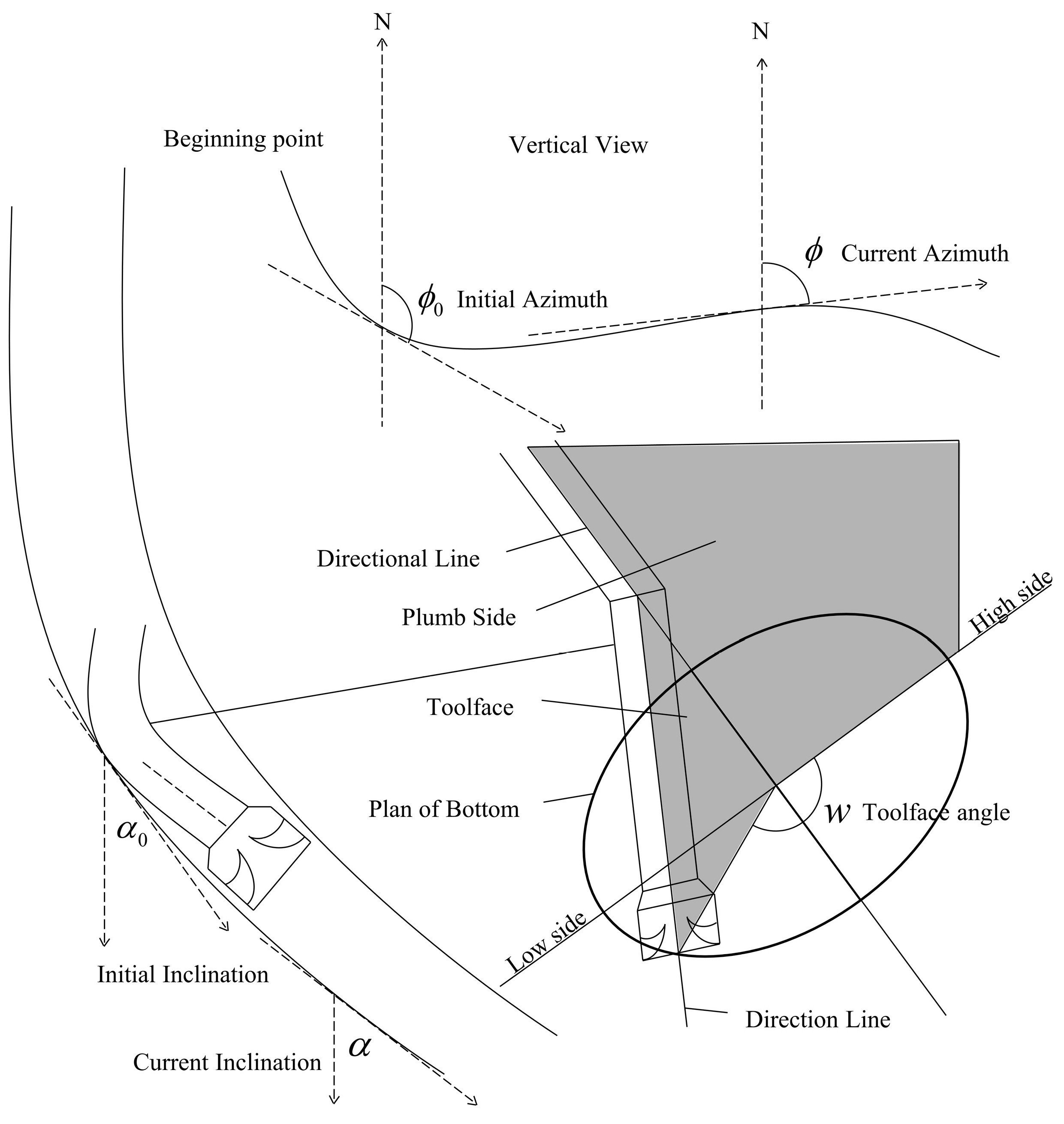
The widely used spatial arc model usually requires constantly changing the toolface angle, which is difficult to implement in the field and results in low operational efficiency. Experts such as Han Zhiyong and Tang Xueping suggested that the Constant-Toolface-angle model should be used for the control of the arc orbit [23]. According to the Constant-Toolface model, as shown in Figure 2, the inclination capacity of the bottom hole assembly (BHA) and the toolface angle remain basically stable, which makes the directional design more rational. Therefore, it is more appropriate to utilize the Constant-Toolface-angle model to describe the borehole trajectory formed by slide drilling than the spatial arc model, and the following basic formulas exist for the Constant-Toolface model:
α α 0 Δ L = κ cos ω
ϕ = ϕ 0 + ( t a n ω ) ln tan α 2 ln tan α 0 2 α α 0 κ sin ω sin α 0 Δ L α = α 0
f α , α 0 = lntan α 2 lntan α 0 2 α α 0
According to L’Hôpital’s rule, it can be known that l i m α α 0 f ( α , α 0 ) = sin α 0 , so the azimuth change rate can be abbreviated as
ϕ = ϕ 0 + f α , α 0 κ Δ L sin ω
Δ N = N N 0 , Δ E = E E 0 , and Δ H = H H 0 represent east coordinates, north coordinates, and vertical depth increments.
When α is equal to α 0 ,
Δ N = s i n 2 α 0 κ s i n ω s i n ϕ s i n ϕ 0 Δ E = s i n 2 α 0 κ s i n ω c o s ϕ 0 c o s ϕ Δ H = Δ L c o s α 0
When α is not equal to α 0 ,
Δ N = 1 κ c o s ω α 0 α 1 s i n α c o s t a n ω d n t a n α / 2 t a n α 0 / 2 + ϕ 1 d α Δ E = 1 κ c o s ω α 0 α 1 s i n α s i n t a n ω l n t a n α / 2 t a n α 0 / 2 + ϕ 1 d α Δ H = s i n α s i n α 0 α α 0 Δ L
Integration needs to be calculated using numerical integration formulas such as Simpson’s numerical integration formula, but it is computationally intensive. A new method with less computational effort is raised by Min Fang using the power series expansion technique, which can figure out the problem [24].
Assuming that the build-up rate of the BHA is known, then the length of a single stand is ∆La, the distance of compound drilling is ∆L1, the distance of slide drilling is ∆L2, and the angle of the toolface is ω. Setting the borehole trajectory formed by slide drilling to a Constant-Toolface-angle curve, the following formula (Formula (5)) is established:
Δ L 1 + Δ L 2 = Δ L a α B α A = κ h Δ L 2 c o s ω ϕ B = ϕ A + κ h Δ L 2 s i n ω s i n α A
α A and ϕ A are the slope and azimuth of the current wellbore, and α B and ϕ B are the slope and azimuth of the scheduled drilling reach. In Formula (7), there are three unknowns, and the other two parameters can be solved by using the three-stage model [25].
c o s ω = c = α B α A κ h Δ L 2 s i n ω = s = ϕ B ϕ A κ h Δ L 2 f α B , α A
The angle ω cannot be uniquely determined by Formula (9) and the periodicity of the trigonometric function, but it can be judged by the formula below. The definition range of the toolface angle is π ω < π .
(1)
When s 2 + c 2 1 , there is no solution.
(2)
When | s | 1 and | c | 1 ,
ω = n o   s o l u t i o n s = c = 0 0 s = 0 , c > 0 π s = 0 , c < 0 arccos c s > 0 arccos c s < 0
It should be noted that if the initial parameters are irrational, the toolface angle of sliding drilling cannot be calculated. The following conditions must be restricted, with l = 0.5   m .
l Δ L 1 Δ L 1 m a x
Δ L 1 max = Δ L g max l , ϕ B ϕ A κ h f α B , α A , α B α A κ h
The toolface angle ω can be uniquely determined in single-stand drilling; then we can make the next single-stand control program design according to the initial parameters calculated by the Constant-Toolface model.

3. Single-Stand Control Design Program

Following Lu Gang’s design concept [17], in addition to designing the control program, given an appropriate compound distance ∆L1 within the range of a single stand, the toolface angle ω for slide drilling and initial parameters can be obtained from Part 2, allowing the inclination and the azimuth at the end of a single stand to reach predetermined values. Given the NEH coordinates of the target point B, there can be many schemes after calculating the distance using the previous parameters; then the scheme that considers this distance to be the smallest is the best.
Set the NEH coordinates at the bottom of the well as (NA, EA, HA), the coordinates at the end of compound drilling as (N1, E1, H1) which can be calculated by Formula (12), and the NEH coordinates at the end of slide drilling as (N2, E2, H2) which can be calculated by Formula (13).
N 1 = N A + Δ L 1 s i n α A c o s ϕ A E 1 = E A + Δ L 1 s i n α A s i n ϕ A H 1 = H A + Δ L 1 c o s α A
N 2 = N 1 + Δ N 2 E 2 = E 1 + Δ E 2 H 2 = H 1 + Δ H 2
The distance d between the endpoint of slide drilling and the target point B is shown in Formula (14), where
d = N 2 N B 2 + E 2 E B 2 + H 2 H B 2
By altering the segment length of compound drilling, it is considered the optimal solution when the distance d reaches its minimum value, and the corresponding compound and slide drilling distances are the best control parameters. Figure 3 shows the curve of the distance d varying with Δ L 1 in an example. When Δ L 1 increases, the distance first decreases gradually, reaches a minimum value, and then gradually increases. The geometric feature of the distance curve is a (unimodal) downward convex continuous curve; there must be a minimum value d for every single stand, so we can employ algorithms to determine the most reasonable compound drilling distance Δ L 1 to obtain a value as close to the target point as possible.

4. Model-Based Intelligent Algorithm

Based on the above design program and previous research, we decided to use the improved Sparrow Search algorithm by integrating the multi-strategy model to optimize such problems. To further verify the algorithm’s performance in handling such issues, we selected two representative algorithms, PSO and the SSA. To verify the accuracy of the results, we designed a full search as Algorithm 1. By conducting extensive calculations, it approximates the optimal control parameters with a precision of 10−6 m, providing a benchmark for comparing the three algorithms and assessing the accuracy of the results. In the experiment, the number of populations is set to 100, and the maximum number of iterations is 400 to ensure that all algorithms are compared under the same conditions; then drilling parameters and wellbore trajectory parameters are taken as the input parameters, and the distance from the target point is taken as the output parameter. The concrete drilling scheme during the next single stand is the research object. In the objective function d is the minimum distance from the target calculated by Formula (14); thus, the corresponding compound drilling distance Δ L 2 can be obtained. The algorithm exhibiting the smallest error compared to Algorithm 1 and the fastest convergence is considered the optimal method.

4.1. Algorithm I—Full Search

With the method of a full search, all the answers are enumerated. Given the compound drilling distance resolution of d L = 10−4 m, equal-distance points are taken in the allowed range of the compound drilling distance.
Δ L 1 n = δ L + n d L n = 0,1 , 2 , , M
If Δ L 1 ( n ) > Δ L 1 m a x , then take Δ L 1 ( n ) = Δ L 1 m a x , and for all Δ L 1 ( n ) , calculate the toolface angle ω by the method of Part 2, and then calculate the distance d ( m )   (Formula (16)) between the endpoint of slide drilling and the target point B, where
d m = m i n d n n = 0,1 , 2 , , M
Then Δ L 1 ( m ) with the corresponding Δ L 1 , Δ L 2 , ω is the approximation of the optimal control parameter. If the length of a single stand is 30 m, define the accuracy of the error as 10−6; for applied engineering the approximation is accurate enough, but the disadvantage is that the calculation is relatively large.

4.2. Algorithm II—Particle Swarm Optimization

Problems can be optimized by simulating group behaviors of the natural world [26], such as bird flocking and foraging. Particle Swarm Optimization (PSO) finds the optimal solution by randomly initializing a group of particles in the solution space and then searching for the optimal solution through iterations. Each particle has two attributes, position and velocity, which represent the potential solution and its search direction and magnitude. The particles update their velocities and positions based on their own experience from optimal positions discovered by the particles themselves during the search process, and the experience of the swarm is derived from optimal discoveries in the swarm of particles, with the aim of finding the globally optimal solution.
The velocity update of the particle follows Formula (17), where
v i t + 1 = w v i t + c 1 r 1 p b e s t i x i t + c 2 r 2 g b e s t x i t
The position update follows Formula (18), where
x i t + 1 = x i t + v i t + 1
The PSO algorithm is used to calculate the single-stand percent by first setting the velocity boundary of the particles to (−2, 2), the position boundary to (0.5, 29.5), the population size to 50, the inertia weights to a maximum of 0.95 and a minimum of 0.45, the self-learning factor to 2, and the population learning factor to 2, and then initializing each parameter including the individual and the population optimum. Then the particles start to swim according to the updated formula until the iteration is completed.

4.3. Algorithm III—Sparrow Search Algorithm

The Sparrow Search algorithm (SSA) mimics the natural behavior of the sparrow in foraging and evading predators, achieving the optimization process of local and global searches. The performance of the Sparrow Search algorithm is better than traditional algorithms such as PSO and emerging algorithms such as the Gray wolf optimization algorithm in single-peak and multi-peak benchmark functions. Sparrow groups are divided into two categories: Explorers and Followers. The Explorers, usually sparrows with high fitness functions, actively seek out food sources, while the Followers obtain food based on the Explorers’ findings. When a group of sparrows is threatened by a predator, some of them will perform a reconnaissance mission. Once a predator is detected, the group will take evasive action to ensure its safety.
In the SSA, the position of each sparrow represents a solution in the solution space. Assuming that the population consists of n sparrows, the fitness value of the sparrow population can be expressed as follows:
F X = f ( [ x 1,1 x 1,2 x 1 , d ] ) f ( [ x 2,1 x 2,2 x 2 , d ] ) f ( [ x n , 1 x n , 2 x n , d ] )
Since the Explorers affect the foraging direction of the whole group, the Explorers can obtain a larger foraging range. In each iteration, the position update of the Explorers (ED) is described as follows:
X i , j t + 1 = X i , j t × exp i α iter max ;   R 2 < S T X i , j t + Q × L ;   R 2 S T
i t e r m a x is a constant that represents the maximum number of iterations. Q is a random number with a normal distribution. t is the number of iterations. α ( 0 , 1 ] is a random number. L represents a 1 × d matrix in which each element is 1. R 2 ( R 2 ( 0 , 1 ] ) and T ( S T [ 0.5 ,   1 ] ) denote the warning and safety values, respectively. When R 2 < S T , this means that there are no predators around, and the Explorers search globally for food. If R 2 S T , this means that some sparrows in the population have discovered the predator, and the Explorers need a normal distribution to perform a random walk to avoid the predator.
The Followers monitored the Explorers’ behavior and moved toward the Explorers as soon as they sensed that the Explorers had found a better food source. The updated location of the Followers is described as follows:
X i , j t + 1 = Q × exp X worst X i , j t i 2 ;   i > n 2 X p t + 1 + X i , j t X p t + 1 × A + × L ;   i n 2
X w o r s e is the current global worst position. X p t + 1 is the best position occupied by the Explorers. A denotes a 1 × d matrix, where each element is randomly assigned as 1 or −1, and A + = A T ( A A T ) 1 . When i > n / 2 , it suggests that the i -th followers with the worse fitness value is most likely to be starving.
Scouts (SDs) account for 10–20% of the total population. The initial positions of these sparrows are randomly generated within the population. Scouts update their positions using Formula (22).
X i , j t + 1 = X best t + β × X i , j t X best t ;   f i > f g X i , j t + K × X i , j t X worst t f i f w + ε ;   f i = f g
K and β are random value that follow a normal distribution in the interval [−1, 1]; X best t is the global best position at the t-th iteration; f i , f g , and f w represent the fitness of the current sparrow, the global best fitness, and the global worst fitness, respectively. ε is a constant that prevents division by zero.
According to the question, set the population size to 100 and the maximum number of iterations to 400. The Explorers’ PD ratio was 0.2. The warning value ST is 0.8, and the sparrow with an awareness of danger (SD) is 0.2.

4.4. Algorithm IV—Improved Sparrow Search Algorithm

4.4.1. Updating Explorers’ Location with Nonlinear Decreasing Weights

In the iterative process of the SSA, the discoverer’s position is often updated with a fixed weight, which may lead the algorithm to converge to the local optimal solution prematurely rather than the global optimal solution in the search process. In order to overcome this defect, the nonlinear decreasing weight strategy is introduced to optimize the location update mechanism of the explorer so that it can search the solution space more widely and avoid falling into the trap of the local optimum. The updating formula of the Explorers’ location with the nonlinear decreasing weight is as follows:
X i , j t + 1 = g × X i , j t × exp i α iter max ;   R 2 < S T g × X i , j t + Q × L ;   R 2 S T
g = i t e r m a x i t e r m a x t
g is the update weight. As the number of iterations increases, the weight decreases nonlinearly. During the later search stages, the Explorers’ scope gradually narrows, transforming into a more detailed local search. This process enhances the accuracy of locating results near the global optimum, thereby improving the accuracy of the results.

4.4.2. Levy Flight Strategy

A Levy flight is characterized by its combination of long-range leaping and short-range detailed searches, which improves the Explorers’ global search ability. The algorithm can prompt the Explorers to perform a broad range of leaps with a certain probability so as to jump out of the local optimal region and improve the randomness and diversity of the solutions. The update formula of the Levy flight position is as follows:
x i t = x i t + l l e v y λ
l represents a step size control parameter, where l = 0.01 ( x i ( t ) x p ) . x p represents the current optimal solution. l e v y λ represents the search path, with l e v y ~ u = t λ , 1 < λ 3 . The Levy flight schematic diagram is shown in Figure 4, and the Levy flight path is obtained using the Mantegna algorithm, where
s = μ | ν | 1 / γ μ ~ N ( 0 , σ μ 2 ) , ν ~ N ( 0 , σ ν 2 ) σ μ = Γ ( 1 + γ ) sin ( π γ / 2 ) γ × Γ [ ( 1 + γ ) / 2 ] × 2 ( 1 + γ ) / 2 1 / γ
By integrating the Levy flight strategy with nonlinear decreasing weights, the search ability of the Explorers is significantly enhanced, leading to the generation of high-quality solutions.

4.4.3. Updating Followers’ Location with the Cauchy Mutation Strategy

In the SSA Followers usually forage around the optimal explorers in order to obtain a better solution to the optimization problem. The Cauchy mutation strategy improve the location update mechanism of Followers. The updated position of the Followers is as follows:
x i , j t + 1 = X best t + cauchy 0,1 X best t
cauchy ( 0 , 1 ) is a standard Cauchy function, where
f x = 1 π 1 x 2 + 1 , < x <
The Cauchy distribution generates the mutation term, which enhances the diversity and global exploration ability of the algorithm, thus allowing the algorithm to flexibly switch between a small-scale detailed search and large-scale jumping exploration.

5. Computational Case

To evaluate the performance of the three algorithms, we created two cases to assess their efficiency and accuracy. We used Algorithm 1 to calculate the slide distance and the distance between the endpoint of the corresponding scheme and the target point. The other three intelligent algorithms were compared with Algorithm 1 once the iterations stabilized. The best scheme is the one with the fastest convergence and the closest distance to the target point 1.

5.1. Case 1

The assembly design of the bottom hole features a build-up rate of 8°/30 m ( k h ). It has a single-stand length of 30 m, an initial toolface angle of 60°, an initial well inclination of 30° ( α 0 ), and an azimuth of 120°. The toolface angle ω calculated using the method outlined in Part 2 is 62.8731°. Utilizing these data, the inclination, azimuths, and coordinate increments at the end of the single stand can be calculated, as shown in Table 1. MD and TVD represent the measured depth and the true vertical depth, respectively.
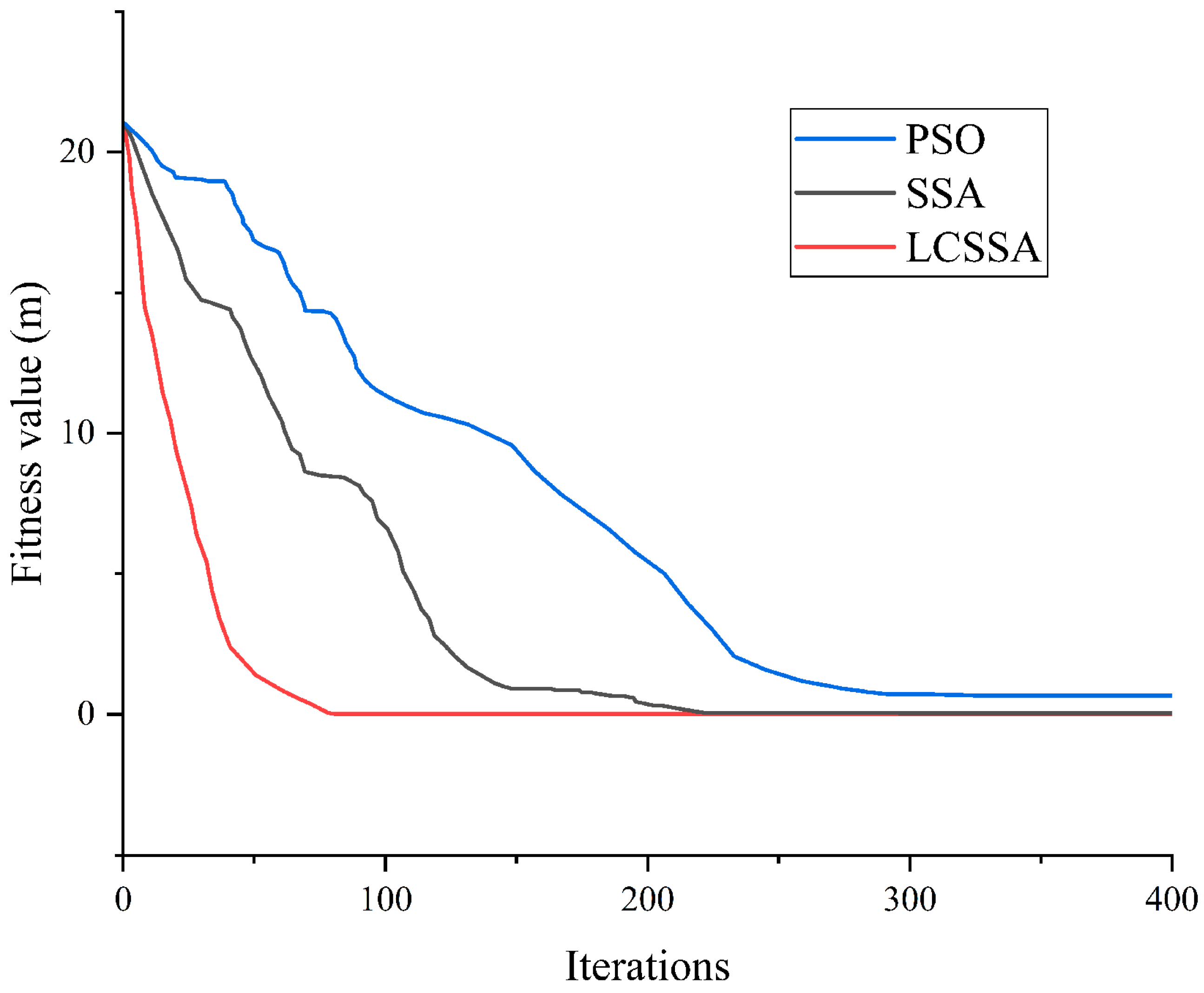
The number of iterations for each algorithm satisfies the criteria and reaches the final stable value. The results indicate that the three algorithms can approximate the minimum value of the objective function presented in Table 2; the results maintain a fairly high numerical accuracy of 10−6. Among them, the LCSSA outperforms the other two algorithms in the design scheme; it has the minimum error with the design situation and the fastest convergence speed, as shown in Figure 5.

5.2. Case 2

The initial design trajectory aimed to reach a depth of 2550 m with a planned inclination of 34.19° and an azimuth of 124.34°.
The trajectory data of the wellbore extracted from the well in the field are presented in Table 3. The drilling parameters are optimized using the “Compound + Slide” drilling method. The designed BHA features a build-up rate of 10°/30 m. It has a single-stand length of 30 m and an initial toolface angle of 320°. The calculated toolface angle ω is 305.6860°. The initial bottom hole inclination α 0 is 29.58, and the azimuth is 135°.
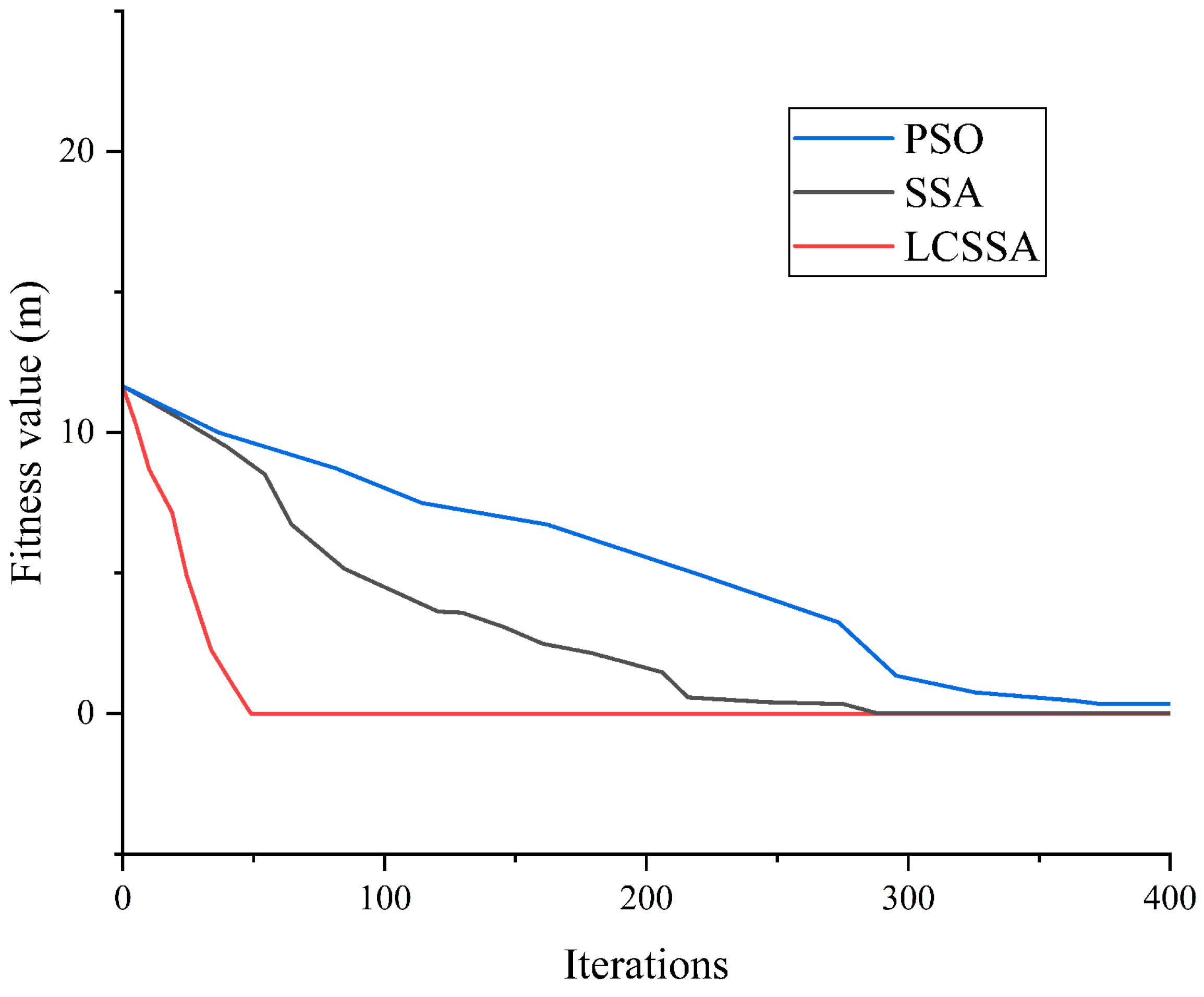
When each algorithm reaches the final stable value, the results of Case 2 are shown in Table 4. The three algorithms can reach the target point after adjusting the parameters multiple times. The LCSSA also performs the best in the field scheme, achieving the minimum error and the fastest convergence speed when dealing with this type of problem, as shown in Figure 6.

5.3. Analysis of the Case

In theory, all three algorithms share the same time complexity for solving this type of problem, differing only in the constant factors. According to the results of the two cases, the LCSSA shows better convergence performance and drilling accuracy, whereas PSO is less effective in addressing this type of problem. The convergence curves of the LCSSA are shown at the bottom of the distribution. The lower the value reached in the optimization process, the higher the optimization accuracy. In terms of convergence speed, the convergence curve of the LCSSA often appears at the inflection point before the other algorithms. At most, it achieves an average convergence time of 0.08 s within 50 to 85 iterations, increasing the speed by 38% over the SSA. The sharp drop in the LCSSA curve reflects the enhanced ability between the global and local searches introduced by the Levy flight, nonlinear decreasing weights, and the Cauchy mutation, which enable the algorithm to escape local optima rapidly and refine the solution efficiently. In addition, the LCSSA achieves the minimum error and reduces the deviation from the planned trajectory by over 30% compared with the SSA.

6. Field Application

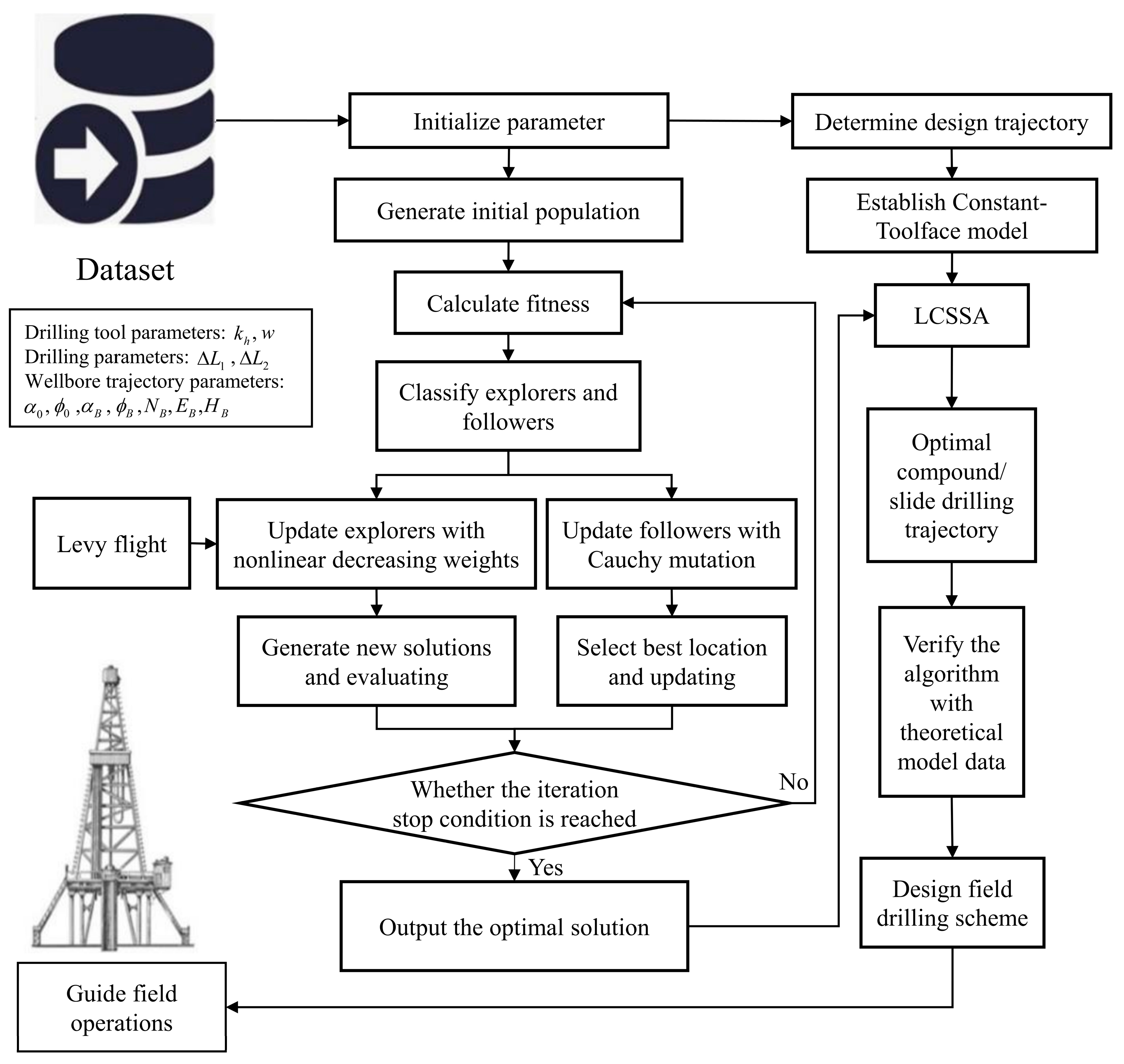
The drilling test was conducted in the Sichuan Basin, where complex geological formations presented significant challenges to directional drilling. SC-8 is a two-dimensional shale gas horizontal well located in central Sichuan. The target reservoir required precise well placement to maximize hydrocarbon recovery. Field engineers found that, after predicting the build-up rate using the proposed algorithm, inexperienced engineers often struggle to accurately determine the optimal timing for switching between slide drilling and compound drilling. Even for experienced engineers, significant errors may occur in mode transitions during actual operations because they do not know the exact proportion of slide drilling for the next single stand, requiring continuous adjustments to align with the planned trajectory. Figure 7 shows a roadmap for applying the improved Sparrow Search algorithm with optimization strategies to drilling engineering. Based on the initial conditions, engineers design the approximate trajectory and input the relevant initial parameters into the LCSSA and the Constant-Toolface model. Through the process, the optimal compound/slide drilling trajectory is determined. The optimal drilling distance per 30 m and the optimal drilling program at the build-up point are derived. The algorithm is verified with theoretical model data, and the final optimal solution is output to guide field operations and design the field drilling scheme.
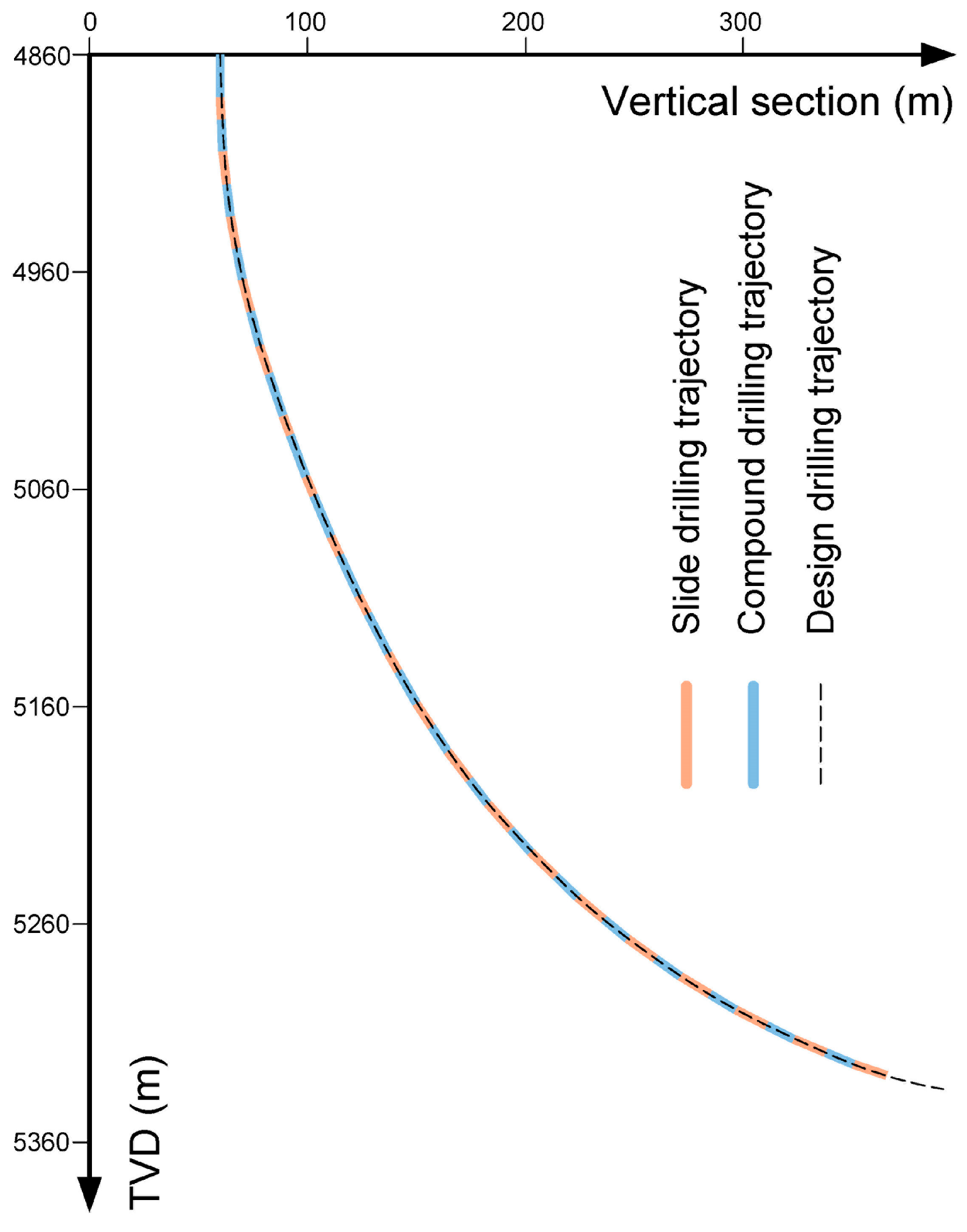
According to the complex geological conditions, we designed a drilling trajectory from 4860 m to 5460 m, as shown in Table 5. The wellbore structure is illustrated in Figure 8. The initial bottom hole inclination is 0°, and the azimuth is 233.42°. The initial toolface angle is 80°, while the calculated toolface angle ω is 76.86°.
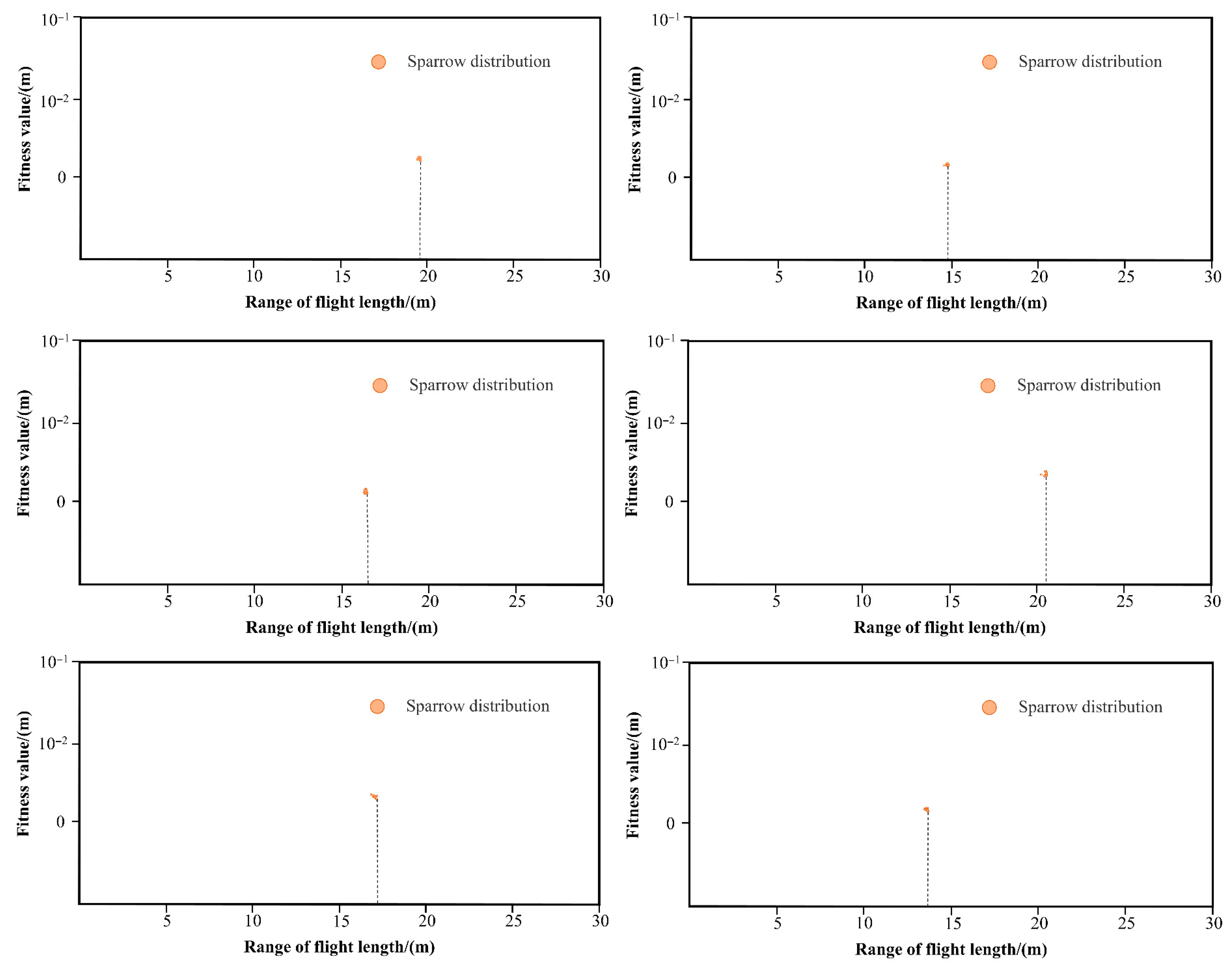
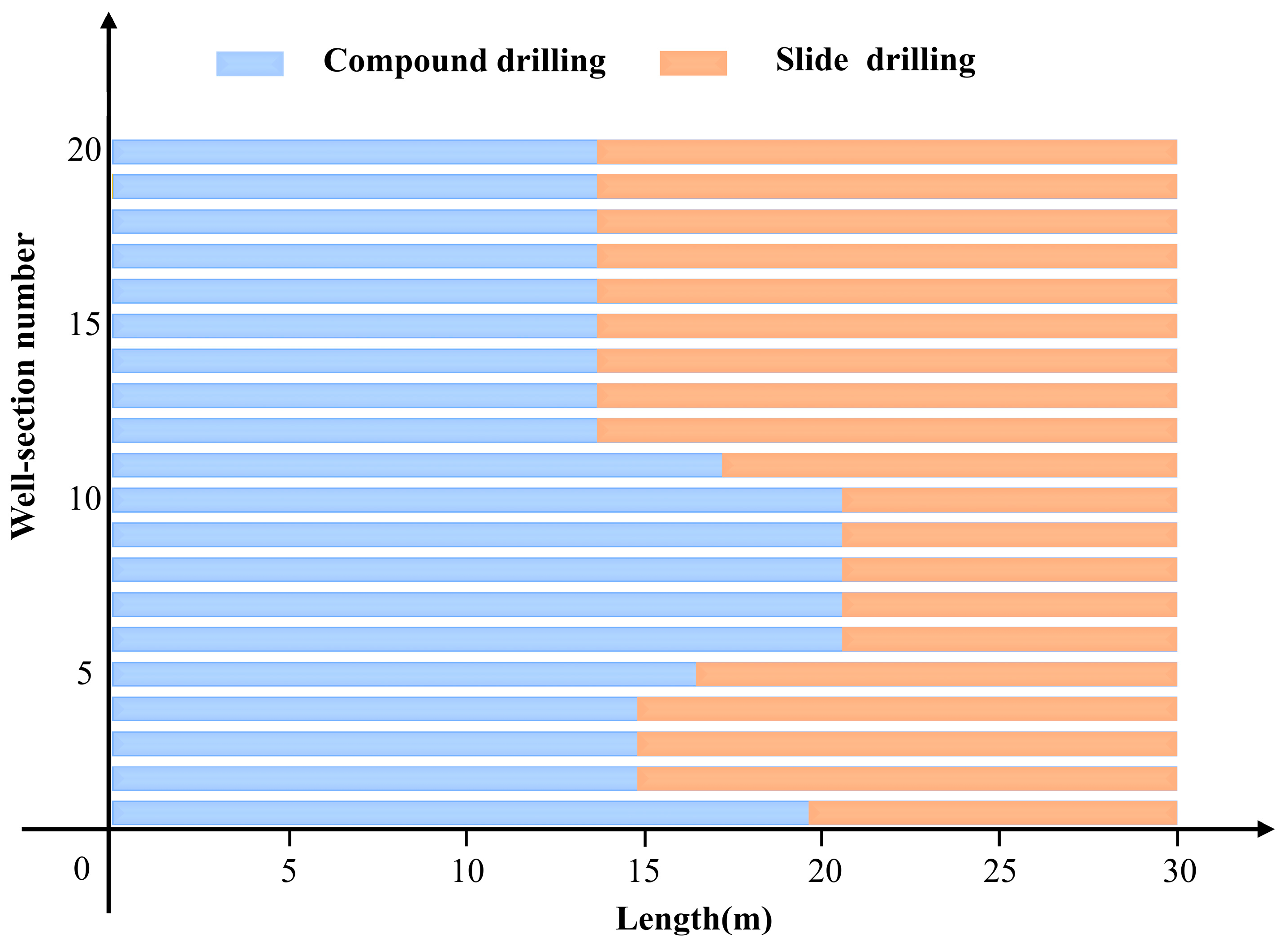
According to the results from two cases, the SSA demonstrated exceptional performance in terms of convergence speed and accuracy, we integrated the SSA into the drilling workflow to optimize drilling parameters, with the algorithm dynamically adjusting the slide and compound drilling distances based on real-time data from MWD systems. Given the process parameters and the target trajectory, we combined the Constant-Toolface model with the LCSSA to predict the optimal drilling scheme for each stand using the “Compound + Slide” method. Subsequently, in the horizontal well build-up section, six alternative drilling schemes are adopted to avoid hazardous formations. Figure 9 illustrates the final computational results of each scheme. In the corresponding sparrow-distribution plot, the abscissa indicates the compound drilling distance, while the ordinate shows the fitness values. The lower the sparrow distribution lies, the closer the solution is to the target point. We developed the detailed drilling plan based on the calculation results of every single stand, as shown in Figure 10, with the optimal design scheme summarized in Table 6.
In traditional drilling processes, engineers develop plans based on their experience, considering factors like formation conditions and the target location. This often results in a zigzag-shaped drilling trajectory, which increases costs, reduces efficiency, and complicates future anti-collision monitoring. However, after multiple applications and tests in adjacent wells, optimized drilling parameters significantly improved trajectory accuracy. Compared to the traditional method, the deviation from the planned trajectory has been reduced by over 25%, restricting it to within 0.005 m per stand. Additionally, the drilling time was reduced by 18% compared to previous operations, thus demonstrating significant efficiency gains. Based on the design scheme, field engineers successfully drilled the trajectory that meets the engineering requirements and reaches the target point, as shown in Figure 11. It was reported that integrating the LCSSA into the drilling control system enhanced operational consistency, reduced reliance on manual adjustments, and improved drilling efficiency and trajectory quality. These enhancements collectively validated the algorithm’s practical applicability.

7. Conclusions

For the on-site control of a 30 m single stand, a mathematical model for compound + slide drilling is established using a line segment and a Constant-Toolface curve, and we provided the method of calculating the proportion of slide and compound drilling according to the initial parameter under varied conditions.
Compared to the full search method, three algorithms are proposed based on optimization principles. These algorithms are verified by two cases using the theoretical model. The results show that Particle Swarm Optimization, the Sparrow Search algorithm, and the improved Sparrow Search algorithm can calculate the shortest distance from the target point. By comparison, the improved Sparrow Search algorithm has the minimum error closest to the target position, making it the most similar to the actual project.
By integrating the algorithm into field applications, field directional well engineers can design single-stand drilling schemes. The LCSSA has enhanced drilling accuracy, efficiency, and safety by optimizing parameters. It also shows great potential in transforming directional drilling operations. For future work, we will further refine the LCSSA by incorporating additional real-time data sources, such as downhole pressure and temperature sensors, to enhance its adaptability to dynamic drilling conditions. Additionally, future research could investigate automated drilling control systems with various algorithms to enable fully autonomous drilling operations with minimal human intervention, such as real-time control of the build-up rate and the toolface angle, thereby collectively promoting the transformation of directional drilling from experience-driven to data-intelligent-driven practices. Overall, the new method positively impacts the sustainable development of the oil and gas industry. It takes an important step toward the global closed-loop intelligent drilling system.

Author Contributions

Conceptualization, H.Y. and Y.L.; methodology, Y.L.; software, Y.L.; validation, H.Y. and Y.L.; formal analysis, Y.L.; investigation, Y.L.; resources, Q.L. and X.W.; data curation, Q.L. and T.Z.; writing—original draft preparation, H.Y. and Y.L.; writing—review and editing, H.Y. and Y.L.; visualization, Y.L.; supervision, X.W. and T.Z.; project administration, Q.L. and T.Z.; funding acquisition, H.Y. and Q.L. All authors have read and agreed to the published version of the manuscript.

Funding

This research was supported by the Natural Science Foundation of Sichuan, China, (2024NSFSC0205) and the National Key R&D Program of China (2019YFA0708302).

Institutional Review Board Statement

Not applicable.

Informed Consent Statement

Not applicable.

Data Availability Statement

The datasets presented in this article are not readily available because the data are part of an ongoing study and due to technical limitations. Requests to access the datasets should be directed to corresponding author.

Conflicts of Interest

Authors Xianzhu Wu Chuanqing is employed by the company Drilling Engineering Company Limited, CNPC, Chengdu 610066, China. All the authors declare that the research was conducted in the absence of any commercial or financial relationships that could be construed as a potential conflict of interest.

Nomenclature

α , α 0 —the inclination at any depth of the wellbore and at the initial well depth; ϕ , ϕ 0 —the azimuth at any depth of the wellbore and at the initial well depth; κ —borehole curvature; ω —the angle of the toolface; Δ L a —the length of a single stand; Δ L 1 —the distance of compound drilling; Δ L 2 —the distance of slide drilling; Δ N , Δ E , and Δ H —north and east coordinates and TVD increments; α A and ϕ A —the slope and azimuth of the current wellbore; α B and ϕ B —the slope and azimuth of the scheduled drilling reach; v i ( t + 1 ) and d v i ( t ) —the velocity of particle i at the next iteration t + 1 and the current iteration t ; w —the inertia weight, which controls the retention of particle velocity and affects the algorithm’s global search ability; c 1   and d c 2 —the acceleration coefficients, which correspond to the individual learning factor and the social learning factor; r 1 and d r 2 —random numbers within the interval [0, 1], adding randomness to the algorithm; p b e s t i and d g b e s t —the individual best position that particle i has found so far and the global best position that the entire swarm has found so far; x i ( t ) and d   x i ( t + 1 ) —the position of particle i at the current iteration t and the next iteration t + 1 ; F —the fitness value; d —the data dimension; t —the current number of iterations; i t e m m a x —a constant that represents the maximum number of iterations; X i j —the position of the i-th sparrow in the j-th dimension; Q —a random number with a normal distribution; X p t + 1 —the best position occupied by the Explorers; X w o r s e —the current global worst position; X best t —the global best position at the t-th iteration; β —a step size control parameter that follows a normal distribution with a mean of zero and a variance of one; g —the update weight.

References

  1. Han, Z.Y. Design and Calculation of Directional Drilling; China Petroleum University Press: Dongying, China, 2007. [Google Scholar]
  2. Liu, X.S. Geometry of Wellbore Trajectory; Petroleum Industry Press: Beijing, China, 2006. [Google Scholar]
  3. Coffey, S.; Groover, A. Achieving Automated Directional Drilling Across Us Onshore Basins. In Proceedings of the IADC/SPE International Drilling Conference and Exhibition, Galveston, TX, USA, 3–4 March 2020. [Google Scholar]
  4. Coffey, S.; Groover, A. Improvements in Slide Quality and Execution Speed Through Automation. In Proceedings of the 2019 AADE National Technical Conference and Exhibition, Denver, CO, USA, 9–10 April 2019. [Google Scholar]
  5. Pollock, J.; Stoecker-Sylvia, Z.; Veedu, V.; Panchal, N.; Elshahawi, H. Machine Learning for Improved Directional Drilling. In Proceedings of the Offshore Technology Conference, Houston, TX, USA, 30 April–3 May 2018. [Google Scholar]
  6. Zhao, Y.; Zalluhoglu, U.; Marck, J.; Demirer, N.; Morari, M. Model Predictive Control for Mud Motor Operation in Directional Drilling. In Proceedings of the 2019 American Control Conference (ACC), Philadelphia, PA, USA, 10–12 July 2019. [Google Scholar]
  7. Zalluhoglu, U.; Gharib, H.; Marck, J.; Demirer, N.; Darbe, R. Steering Advisory System for Mud Motors. In Proceedings of the SPE/IADC International Drilling Conference and Exhibition, Hague, The Netherlands, 5–7 March 2019. [Google Scholar]
  8. Pehlivantürk, C.; D’angelo, J.; Cao, D.; Chen, D.; Ashok, P.; Van Oort, E. Slide Drilling Guidance System for Directional Drilling Path Optimization. In Proceedings of the SPE/IADC International Drilling Conference and Exhibition, Hague, The Netherlands, 5–7 March 2019. [Google Scholar]
  9. Pehlivantürk, C.; Chen, D.; Ashok, P.; van Oort, E. Path Advisory for Slide Drilling Using a Nonlinear Wellbore Propagation Model and Genetic Algorithm. J. Pet. Sci. Eng. 2019, 179, 734–741. [Google Scholar] [CrossRef]
  10. Angelo, J.D.; Khaled, M.S.; Ashok, P.; van Oort, E. Pareto Optimal Directional Drilling Advisory for Improved Real-Time Decision Making. J. Pet. Sci. Eng. 2022, 210, 110031. [Google Scholar] [CrossRef]
  11. Hausher, A.; Kern, S.; Chmela, W.; Cantwell, J.; Mims, K. Automated Sliding: Efficiencies Achieved in the Next Stage of Drilling Automation. In Proceedings of the IADC/SPE International Drilling Conference and Exhibition, Galveston, TX, USA, 3–4 March 2020. [Google Scholar]
  12. Yu, Y.; Chen, W.; Liu, Q.; Chau, M. Training an Automated Directional Drilling Agent with Deep Reinforcement Learning in a Simulated Environment. In Proceedings of the SPE/IADC International Drilling Conference and Exhibition, Stavanger, Norway, 8–12 March 2021. [Google Scholar]
  13. Braga, D.C.; Kamyab, M.; Joshi, D.; Harclerode, B.; Cheatham, C. Using Particle Swarm Optimization to Compute Hundreds of Possible Directional Paths to Get Back/Stay in the Drilling Window. In Proceedings of the 2021 SPE Annual Technical Conference and Exhibition, Dubai, United Arab Emirates, 21–23 September 2021. [Google Scholar]
  14. Joshi, D.R.; Kamyab, M.; Braga, D.C.; Cheatham, C.A. Real-Time Directional Guidance Through Cloud-Based Well Path Optimization. In Proceedings of the SPE/IADC International Drilling Conference and Exhibition, Stavanger, Norway, 7–9 March 2023. [Google Scholar]
  15. Wang, N.; Cheng, Z.; Lu, Y.; He, B.; Ren, G. Automated Slide Drilling System and Multi-Body Dynamics Aided Slide Drilling Simulation. In Proceedings of the SPE Digital Energy Conference and Exhibition, Woodlands, TX, USA, 3–5 March 2015. Society of Petroleum Engineers. [Google Scholar]
  16. Cheng, Z.B.; Ren, G.X.; Li, B.H.; He, B. Directional Drilling Dynamics and Control Theory Research and Application; China Petrochemical Press: Beijing, China, 2021. [Google Scholar]
  17. Lu, G.; Zhong, X.M.; Li, S.Z.; Lai, J.Q. A New Calculation Method of The Well Trajectory of Joint Control. Oil Drill. Prod. Technol. 2021, 43, 146–150, 159. [Google Scholar]
  18. Xue, J.; Shen, B. A Novel Swarm Intelligence Optimization Approach: Sparrow Search Algorithm. Syst. Sci. Control. Eng. 2020, 8, 22–34. [Google Scholar] [CrossRef]
  19. Li, J.; Wu, Y. Improved Sparrow Search Algorithm with the Extreme Learning Machine and Its Application for Prediction. Neural Process. Lett. 2022, 54, 4189–4209. [Google Scholar] [CrossRef]
  20. Li, J.Y.; Chen, J.; Shi, J. Evaluation of New Sparrow Search Algorithms with Sequential Fusion of Improvement Strategies. Comput. Ind. Eng. 2023, 182, 109425. [Google Scholar] [CrossRef]
  21. Le, M.H.; Li, J. Improved Sparrow Search Algorithm with Multi Strategy Fusion and Application in AGV Path Planning. Foreign Electron. Meas. Technol. 2024, 43, 129–139. [Google Scholar] [CrossRef]
  22. Ke, Y.T.; Wang, Z.; Wang, W.S. Path Planning Based on Integrated Composite Chaotic Adaptive Sparrow Search Algorithm. Modul. Mach. Tool Autom. Manuf. Tech. 2025, 6, 36–42, 48. [Google Scholar]
  23. Han, Z.Y. The New Techniques of Well Trajectory Design and Well Path Control Fit For 3d-Direction Wells. Pet. Drill. Tech. 2003, 31, 5. [Google Scholar]
  24. Fang, M.; Lu, G. Semi-Analytic Computing of Constant-Tool-Face-Angle Curves. J. Tongji Univ. (Nat. Sci.) 2008, 36, 844–848. [Google Scholar]
  25. Tang, X.; Hong, D.F.; Sheng, L.M.; Dou, X.R.; Wang, J. Planning Models and Solving Methods for a Well Path with Constant Tool Face Angle. Acta Pet. Sin. 2018, 39, 1193–1198. [Google Scholar]
  26. Lee, S.; Stephen, K.D. Field Application Study on Automatic History Matching Using Particle Swarm Optimization. In Proceedings of the SPE Reservoir Characterization and Simulation Conference and Exhibition, Abu Dhabi, United Arab Emirates, 17–19 September 2019. [Google Scholar] [CrossRef]
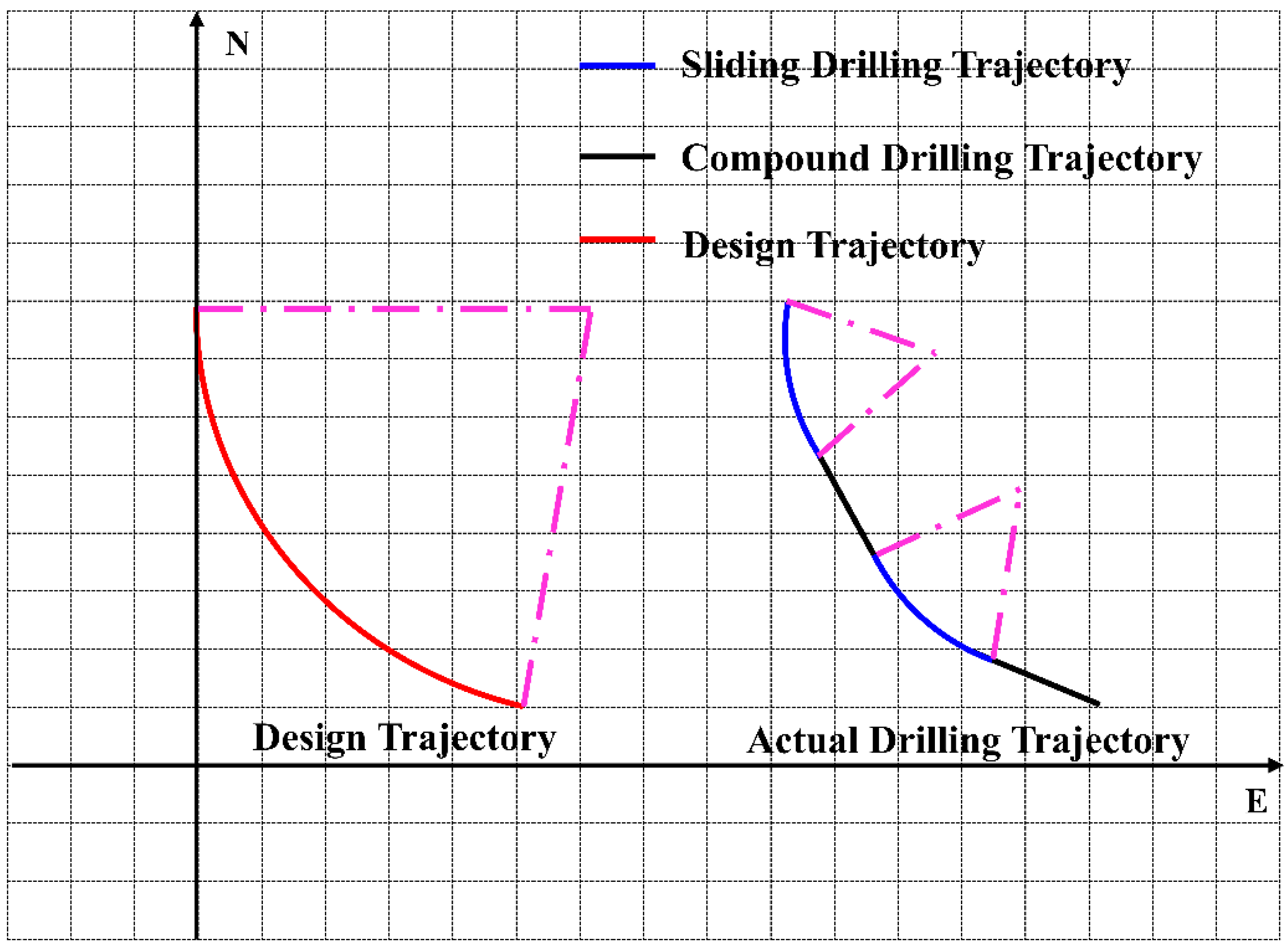
Figure 1. Designed and actual trajectories of the bent-housing motor.
Processes 13 02593 g001
Figure 2. Schematic diagram of drilling parameter calculation.
Processes 13 02593 g002
Figure 3. Variation in the distance from the target point with the compound drilling distance.
Processes 13 02593 g003
Figure 4. Schematic diagram of the Levy flight.
Processes 13 02593 g004
Figure 5. Convergence curve of the three algorithms for Case 1.
Processes 13 02593 g005
Figure 6. Convergence curve of the three algorithms for Case 2.
Processes 13 02593 g006
Figure 7. Roadmap application for the field.
Processes 13 02593 g007
Figure 8. Well structure of SC-8.
Processes 13 02593 g008
Figure 9. Summary of calculation results of a single stand.
Processes 13 02593 g009
Figure 10. Drilling plan for each stand.
Processes 13 02593 g010
Figure 11. Comparison of the design trajectory and the actual trajectory.
Processes 13 02593 g011
Table 1. Initial data of Case 1.
Key PointMD (m)Inclination (°)Azimuth (°)North Increments (m)East Increments (m)TVD (m)
Beginning point030.0000120.0000000
Endpoint30.000032.8049128.9568−7.738412.871725.6080
Table 2. Results of Case 1.
The Type of Algorithm The   Minimum   Value   d of the Objective Function (m) The   Position   Δ L 2 Where the Minimum Value Occurs (m)
Algorithm 1—Full Search0.00356021.060000
Algorithm 2—PSO0.67440022.171602
Algorithm 3—SSA0.04667521.098032
Algorithm 4—LCSSA0.00355821.059736
Table 3. Initial data of Case 2.
Key PointMD (m)Inclination (°)Azimuth (°)North Increments (m)East Increments (m)TVD (m)Borehole Curvature (°/30 m)
Beginning point2520.000029.5800135.00000006.9957
Endpoint2550.000034.1900124.3400−10.098512.176725.4664
Table 4. Results of Case 2.
The Type of Algorithm The   Minimum   Value   d of the Objective Function (m) The   Position   Δ L 2 Where the Minimum Value Occurs (m)
Algorithm 1—Full Search 0.00087918.180000
Algorithm—2-PSO 0.33875016.673415
Algorithm 3—SSA 0.01385618.517832
Algorithm 4—LCSSA 0.00088218.179995
Table 5. Design drilling trajectory of SC-8.
Well Section NumberMD (m)Inclination (°)Azimuth (°)TVD
(m)
North Coordinate
(m)
East Coordinate
(m)
0000000
148600233.424860.0000
248902.67233.424889.99−0.28−0.37
349206.67233.424919.89−1.73−2.33
4495010.67233.424949.54−4.43−5.96
5498014.67233.424978.80−8.34−11.24
6501018.37233.425007.54−13.46−18.14
7504020.57233.425035.82−19.42−26.17
8507022.77233.425063.70−26.02−35.06
9510024.97233.425091.14−33.26−44.81
10513027.17233.425118.08−41.11−55.40
11516029.37233.425144.50−49.58−66.80
12519033.05233.425170.21−58.78−79.21
13522037.33233.425194.73−69.08−93.09
14525041.62233.425217.88−80.45−108.40
15528045.90233.425239.54−92.81−125.06
16531050.18233.425259.60−106.10−142.97
17534054.46233.425277.93−120.25−162.03
18537058.75233.425294.44−135.17−182.14
19540063.03233.425309.03−150.79−203.18
20543067.31233.425321.62−167.01−225.04
21546071.60233.425332.15−183.74−247.59
Table 6. Optimal design scheme for the field.
Section Number of the WellPercent of Slide Drilling (%)Sliding Drilling Length (m)Deviation
(m)
134.5910.380.000801
250.6715.200.003759
350.6715.200.003759
450.6715.200.003759
545.1813.550.001943
631.459.440.000502
731.459.440.000502
831.459.440.000502
931.459.440.000502
1031.459.440.000502
1142.7312.820.000242
1254.4916.350.000946
1354.4916.350.000946
1454.4916.350.000946
1554.4916.350.000946
1654.4916.350.000946
1754.4916.350.000946
1854.4916.350.000946
1954.4916.350.000946
2054.4916.350.000946
Disclaimer/Publisher’s Note: The statements, opinions and data contained in all publications are solely those of the individual author(s) and contributor(s) and not of MDPI and/or the editor(s). MDPI and/or the editor(s) disclaim responsibility for any injury to people or property resulting from any ideas, methods, instructions or products referred to in the content.