Abstract
This research explores supersonic cyclonic separation for natural gas liquefaction (LNG). A 3D computational model was developed using the Eulerian–Eulerian two-fluid framework to simulate spontaneous gas condensation. The model tracks droplet formation/growth mechanisms and employs Reynolds stress modeling (RSM) for turbulence, implemented in Fluent via user-defined functions (UDFs). Validated against experimental data, it accurately predicted condensation onset and shock wave behavior. A prototype separator designed for a natural gas peak-shaving station demonstrated lower temperatures than throttling valves but modest liquefaction efficiency (4.28% at 5 MPa inlet pressure). Two enhancement strategies were tested: (1) injecting submicron LNG condensation nuclei (radius < 1 × 10⁻⁹ m) significantly boosted liquefaction by reducing nucleation energy barriers and suppressing condensation shocks; (2) a multi-stage configuration increased total liquefaction by 156% versus single-stage operation. These findings highlight the technology’s potential for energy-efficient gas processing.
1. Introduction
Liquefied natural gas (LNG) is produced by compressing, cooling, and separating qualified natural gas. Its main component is methane, which is usually stored in a cryogenic storage tank at approximately −161.5 °C and 0.1 MPa. Under standard conditions, its volume is approximately 1/625 of that of the same amount of gaseous natural gas. As a clean energy source, LNG is widely used in fields such as cryogenic engineering and chemical engineering [1]. Conventional natural gas liquefaction technologies include mixed refrigerant liquefaction technology, expansion liquefaction technology, cascade liquefaction technology, etc. [2,3,4]. However, these technologies have drawbacks such as high investment, complex equipment, and high energy consumption.
Research institutions have actively developed supersonic separation as an alternative approach [5]. Key players include Shell Oil, Russia’s ENGO Research Center, Memorial University of Newfoundland, and operators in the Netherlands, Nigeria, and Norway [6]. Garrett proposed an early separator requiring complex fixes like electromagnetic fields or inhibitors to prevent blockages [7]. Twister BV created foundational designs (Twister™ Mark I/II) [8,9]. Based on aerospace aerodynamics achievements, a 3S supersonic separator with low investment and operating costs was developed. This compact device uses a nozzle, cyclone section, and diffuser [10,11]. It offers simplicity and stability but struggles with inlet pressure changes.
Extensive modeling work has enhanced understanding of supersonic condensation processes. A. Shahsavand [12] considered the actual droplet size distribution during the cyclone separation process. The actual movement trajectory of droplets was calculated. Solutions to promote the condensation process by injecting droplets were also proposed. Ma et al. [13] proposed an improved mathematical model. It combines the condensation deposition mechanism and the surface diffusion rate mechanism. This achieves the coupling of turbulence and condensation. The flow field and the process of non-homogeneous condensation were analyzed. Mazen et al. [14] designed a rotating supersonic nozzle expander. Numerical analysis and CFD simulation were performed. Compared with existing supersonic separators, the proposed device significantly enhances the gas cooling and condensation process. Bian et al. [15] studied the supersonic condensation process of methane-ethane binary gas mixtures. The nucleation and droplet growth processes were clarified. The condensation characteristics of natural gas under different operating parameters were analyzed. It was found that higher pressure, lower temperature, or higher ethane content leads to larger nucleation rates and humidity. Bian et al. [16] devised the cyclone nozzle with a center body. The condensation characteristics of methane–ethane binary mixtures under supersonic cyclone conditions were numerically investigated. It was found that the increase in inlet temperature can increase the tangential velocity inside the nozzle and promote the separation of droplets from dry natural gas. Ding et al. [17] explored the flow mechanism inside a supersonic separator. An innovative homogeneous phase nucleation and growth model was included to ensure the model’s comprehensiveness. It was found that the decrease in the diameter or the increase in the concentration of non-homogeneous droplets significantly inhibits homogeneous condensation. Wen et al. [18] used the Navier–Stokes equations of the Reynolds stress model. The natural gas flow in a diffuser was numerically calculated. It was found that the conical diffuser with high-pressure recovery performance is a good choice for supersonic separators. Shooshtari et al. [19] provided a new theoretical approach based on mass transfer rate calculations. It is used to predict the droplet growth process of binary mixtures inside a Laval nozzle. The 3S device was found to reduce the water vapor and hydrogen sulfide content of natural gas to permissible values under all conditions. XU et al. [20] established the entropy production analysis model and the non-equilibrium condensation model. It was found that the supersonic nozzle cyclone intensity should be kept below 0.30. This achieves a balance between the gas handling capacity, liquefaction performance, and energy loss of the supersonic nozzle. Duan et al. [21] developed the mathematical model of hydrogen supersonic condensation in the Laval nozzle model. It was found that the maximum nucleation rate decreases with increasing inlet temperature. The nucleation region of the Laval nozzle becomes wider. The reduction of the inlet temperature provides more subcooling. This allows hydrogen to reach the thermodynamic conditions required for large-scale condensation more quickly. Yang et al. [22] built the physical model for homogeneous condensation of water vapor. It was found that when the boundary layer separates, the vortex population enhances the energy transfer in the vicinity of the shear layer. The separation point is the region with the highest entropy production. Wang et al. [23] compared the predictions of three representative thermodynamic models in the Laval nozzle and SS. The NIST real gas model was found to have the highest prediction accuracy. The inlet pressure significantly affects the separation performance of SS. The cyclone intensity also significantly affects the separation performance and energy conversion rate.
Despite progress, supersonic devices still need improved liquefaction conversion rates. This paper proposes two enhancement methods validated through CFD simulations. This study reviews current research, details the condensation model, describes the device and conditions, compares liquefaction methods, introduces the two enhancement strategies, and presents conclusions.
2. Mathematical Model of Condensation Flow in Supersonic Cyclone
In the process of high-speed movement of a supersonic cyclone separator, natural gas is strongly rotated, condensation and phase transition occur at the same time, the flow situation is complicated, and the flow cross-section parameter distribution is asymmetric. The commonly used two-dimensional simulation cannot accurately reflect the characteristics of various parameters and the mechanism of spontaneous condensation, so a three-dimensional simulation is needed. Based on the Euler two-fluid model, the governing equations that can describe the spontaneous condensation process of natural gas are established. The mathematical model and numerical simulation results are verified by the classical experimental data, which lays a foundation for the study of the mechanism of supersonic cyclone liquefaction of natural gas.
2.1. Mathematical Model of Condensation
2.1.1. Governing Equations
During the model establishment process, some assumptions are introduced. Droplets do not collide or break apart. This implies the droplet size distribution evolution is solely governed by nucleation and growth/evaporation, neglecting coalescence, breakup, and agglomeration effects. This is a significant simplification for dense sprays or high liquid volume fractions. Liquid droplets are assumed to be evenly distributed within the gas phase. This neglects potential spatial clustering or segregation of droplets. The gas phase is assumed to be at sufficiently low pressure such that the ideal gas law and Dalton’s law of partial pressures hold for the gas mixture components.
The two-fluid model is established based on the Euler–Euler method. Both gas and liquid phases are treated as interpenetrating continua. The liquid phase is described by its bulk properties (volume fraction, number density, and average droplet radius) rather than tracking individual droplets (Lagrangian approach). Mass, momentum, and energy equations are established for the gas phase. The gas phase properties involved in these calculations are derived using the BWRS real gas equation of state. The transport equation, considering the mass transfer between gas and liquid phases, is established, and the governing equation of the liquid phase is constructed simultaneously with the droplet nucleation and growth theory. The gas–liquid coupling through the source phase is used to construct the governing equations suitable for describing the complex flow process.
The governing equations of gas flow are shown in Equations (1)–(3):
where the subscripts i and j correspond to the x-axis and y-axis, respectively. t denotes time, and x stands for the Cartesian coordinate. ρ is the density, and the subscript g denotes the gas phase. u is the velocity, T refers to temperature, p indicates pressure, and E is total energy. keff is the effective thermal conductivity, and τeff denotes the effective stress tensor.
The governing equations of liquid phase flow are shown in Equations (4)–(6):
where Ys is the humidity, Ns is the number of droplets, and rd is the average radius of the droplets.
Sm, Su, Sh, and Sym are the source terms of mass, momentum, energy, and gas–liquid phase transport equations, respectively, and the expressions are shown in Equations (7)–(11):
where hlg signifies the latent heat of phase change, ms is the mass of a single vapor molecule, and rc is the critical radius. The subscript l denotes the liquid phase.
JS is the droplet nucleation rate; the classical nucleation theory is used to calculate the formula. The expressions are shown in Equations (12)–(14):
where Tr denotes relative temperature, Rg is the gas constant, k is the Boltzmann constant, S refers to the supersaturation degree, σ is the surface tension of droplets, and σ∞ is the surface tension of the liquid plane.
is the droplet growth rate, calculated by the Gyarmathy model. This model accounts for kinetic and continuum growth regimes but assumes spherical, isolated droplets and may have limitations for very small droplets or high growth rates. Its expressions are shown in Equations (15) and (16).
where Ts is the temperature of the droplet, Prg is the Prandtl number of the vapor phase, and λg is the thermal conductivity of the vapor phase.
2.1.2. Turbulence Model
In this paper, the flow field has streamlined bending and a cyclone. However, the Reynolds stress model (RSM) is more rigorous than the single equation model and double equation model in considering streamline bending, vortex, rotation, and rapid change of tension, and the calculation accuracy of complex flow is higher. Therefore, the RSM model is chosen as the turbulence model.
The Reynolds stress transport equation model is shown in Equation (17):
where is the convective term, is the turbulent diffusion term, is the molecular viscous diffusion term, is the shearing stress generation term, is the buoyancy generation term, is the pressure-strain term, is the viscous dissipation term, and is the system rotation generation term.
2.1.3. Numerical Solution
- Solution method
C language is used to write user-defined function (UDF) for the source term of the governing equations, custom scalar (UDS) is applied to the transport equation, and Fluent is embedded to achieve modeling. In the established model, the gas–liquid flow control equations, turbulent kinetic energy equations, and dissipation rate equations are all discredited by the second-order upwind scheme, and the relaxation factor is constantly adjusted during the solving process to avoid divergence in the solving process.
- 2.
- Boundary conditions and initial conditions
Boundary condition: The inlet boundary of the flow parameter is set as the pressure inlet, the outlet boundary is set as the pressure outlet, and the inlet boundary of the condensation parameter is set as the first type of boundary condition, .
Initial conditions: Considering that condensation parameters are very sensitive and change violently in the flow field, the calculation results of non-condensing flow are used as the initial data of the flow field calculation to avoid calculation divergence.
- 3.
- Grid division and independence analysis
ICEM software 2022 was used for grid division. For the entire calculation domain, structured grids were adopted for 2D calculations, and unstructured grids for 3D calculations. Local mesh refinement was performed in areas with large velocity gradients, such as near the Laval nozzle throat, diffuser inlet, and cyclone.
Grid independence verification was conducted for both the 2D structured grids and 3D unstructured grids. Under the same inlet and outlet boundary conditions, calculations were performed with different mesh densities. The final mesh count was determined when the results of two consecutive calculations agreed closely.
The near-wall region treatment is unavoidable for all models. Turbulence models, which are developed for high Reynolds numbers, only apply to the turbulent core region. Near the wall, turbulence pulsations weaken gradually due to the damping effect of molecular viscosity. Thus, the wall function method was used to handle the near-wall flow in this study.
- 4.
- Convergence criterion
Each residual error is less than 1 × 10⁻³, and the relative error of import and export mass flow is less than 1%.
2.1.4. Model Verification
Wyslouzil et al. [24] obtained a series of experimental data by measuring the static pressure distribution along the nozzle axis and judging the location and intensity of spontaneous condensation. The results of the spontaneous condensation of humidified nitrogen in the Laval nozzle were published in 2000. In this paper, the experimental data are used to verify the mathematical model of supersonic cyclone condensation flow. The structure and operating parameters of the experimental nozzle are shown in Table 1.

Table 1.
Nozzle structure and experimental parameters.
Where is the gradually shortened length of the nozzle, is the length of the expanding section of the nozzle, is the ratio of the outlet area of the expanding section to the area of the nozzle throat, and are the width and height of the nozzle throat, is the inlet pressure of the nozzle, is the inlet temperature, and is the partial pressure of the inlet water vapor.
Figure 1 shows the calculation model of the experimental nozzle. Quadrilateral structured meshes are used for subdivision, with local encryption in the throat and the progressive segments. A grid sensitivity analysis is conducted to determine the optimal mesh density. Results from simulations using different mesh sizes (3200, 5655, and 8900 elements) are compared. The comparison shows that at 5655 elements (corresponding to 5840 nodes), the relative deviation of key parameters is less than 1%. This indicates that the results become mesh-independent at this density. Subsequently, a time-step sensitivity analysis is performed for the transient simulation. Three time steps (1 × 10⁻⁷ s, 5 × 10⁻⁸ s, and 1 × 10⁻⁸ s) are tested. The transient evolution curves of droplet nucleation rate in the nozzle throat and gas-phase velocity at the outlet are examined. Results demonstrate that curves obtained with a 5 × 10⁻⁸ s time step closely match those from the smaller 1 × 10⁻⁸ s step. The maximum deviation in peak values is below 2%. Therefore, a time step of 5 × 10⁻⁸ s is selected for the transient simulation to meet accuracy requirements efficiently.
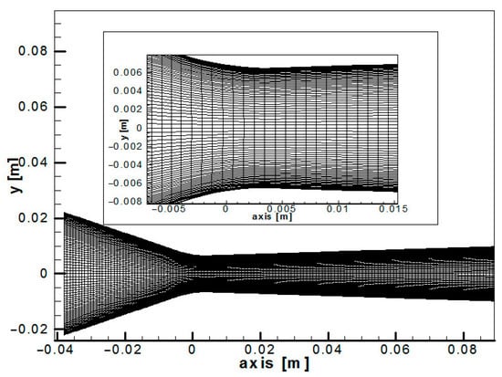
Figure 1.
The structure and experimental parameters of the Wyslouzil experimental nozzle.
Figure 2 shows the comparison between the static pressure ratio of the nozzle axis and experimental measurement data under three different inlet partial pressures of water vapor. x denotes the axial distance from the nozzle throat. The two-fluid model predictions show good agreement with measurements across all tested conditions and flow regimes (pre-/post-condensation). By accounting for boundary layer effects, the simulations yield more realistic flow behavior.
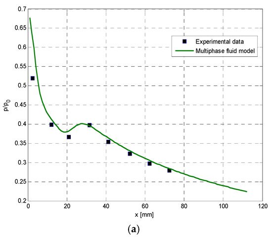
Figure 2.
Comparison of static pressure ratio of nozzle axis with experimental data. (a) Inlet steam partial pressure 1.0 kPa; (b) inlet steam partial pressure 0.50 kPa; (c) inlet steam partial pressure 0.26 kPa.
3. Structure and Operating Conditions of Natural Gas Supersonic Cyclone
Taking an LNG peak-loading station in Petrochina Changqing Oilfield as an example, the components are shown in Table 2. The parameters in Table 2 refer to the specific components of the natural gas at this station and their corresponding molar fractions. These data were obtained through on-site sampling of the natural gas at the station, followed by detection and analysis using a gas chromatograph. The natural gas processing capacity of the station is 4706 Sm3/h, the inlet pressure of the gas source is 4 MPa, the initial temperature is 300 K, and the outlet pressure of the unit forming LNG after treatment is 0.9 Mpa. The integrated cascading liquefaction process is adopted. The storage conditions of the LNG product storage tank are 112.5 K and 0.11 MPa. The supersonic cyclone separator replaces the throttling refrigeration valve (inlet pressure 2 MPa) installed in the process system. The overall structure of the nozzle is shown in Figure 3.
Table 2.
Natural gas components.
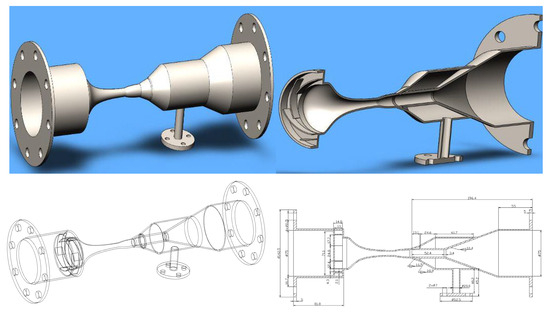
Figure 3.
Structure design of natural gas liquefaction supersonic cyclone separator.
4. Comparison of Treatment Effects of Different Liquefaction Methods
The supersonic cyclone separator can achieve natural gas liquefaction and gas–liquid separation, but its overall liquefaction rate remains low, as shown in Table 3. This study analyzes the temperature drop and liquefaction rate of supersonic cyclone separation devices under different inlet pressures and pressure drops. Results indicate that the liquefaction rate increases with rising inlet pressure and pressure drop but remains generally low. For example, when the inlet pressure is 5 MPa, the liquefaction rate is only 4.28%. A comparison with the throttle valve under the same inlet pressure and pressure drop shows that the throttle valve cannot liquefy natural gas, and its temperature drop is smaller than that of the supersonic cyclone separator. This confirms that despite its low liquefaction rate, the supersonic cyclone separator performs better than the throttle valve.
Table 3.
Comparison of the liquefaction rate of the supersonic cyclone separating device and the throttle valve.
It can be concluded that a supersonic cyclone separation device alone is difficult to achieve large-scale natural gas liquefaction. Therefore, it is necessary to continue studying the method of improving the liquefaction rate and the overall liquefaction process for supersonic cyclone separation devices.
5. Method of Improving Liquefaction Rate
The analysis shows that the natural gas liquefaction rate at the nozzle outlet remains low. A single device can not achieve industrial-scale liquefaction. Therefore, improving the liquefaction rate is essential for practical application in the natural gas liquefaction industry.
5.1. Additional LNG Condensation Core to Improve the Liquefaction Rate
Gas condenses into droplets through two mechanisms: homogeneous nucleation and heterogeneous nucleation. Homogeneous nucleation occurs in pure gas without impurities or existing droplets. Here, condensation nuclei form solely by the aggregation of gas molecules. Heterogeneous nucleation occurs when sufficient impurities or droplets are present in the gas. Condensation then forms around these foreign particles, acting as nuclei. Homogeneous nucleation requires a higher degree of gas supersaturation than heterogeneous nucleation. Because heterogeneous nucleation requires lower supersaturation, it serves as an effective aid in many industrial processes. Therefore, to enhance natural gas liquefaction in nozzles, adding condensation nuclei is proposed. These nuclei reduce the condensation free energy barrier, promoting the liquefaction process. The concentration and radius of the condensation nuclei critically influence liquefaction efficiency in the nozzle. Consequently, analyzing the impact of these two parameters is essential.
- Influence of condensation core concentration on liquefaction efficiency
To prevent external critical core contamination, liquefied natural gas (LNG) reflux is proposed as the condensation core medium. Figure 4 presents the flow and condensation parameters along the nozzle’s central axis under the following conditions: inlet temperature 180 K, inlet pressure 2 MPa, condensation core radius 1 × 10⁻⁹ m, and core concentrations of 0, 1 × 10⁸, 1 × 10⁹, 1 × 10¹⁰, 1 × 10¹¹, and 1 × 10¹² per kg.
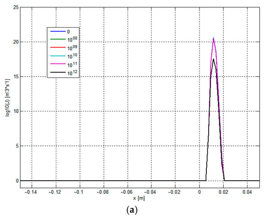
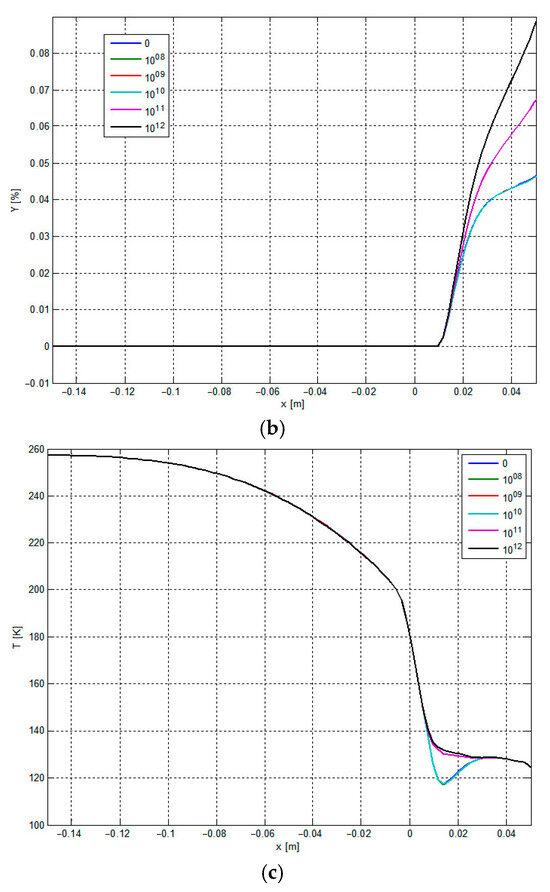
Figure 4.
Distribution of flow and condensation parameters at the central axis of the nozzle at different external condensation core concentrations. (a) The effect of the core concentration on condensation nucleation. (b) The influence of the core concentration on the humidity. (c) The effect of adding core concentration on the condensation shock wave.
Figure 4a reveals that increasing condensation core concentration suppresses spontaneous condensation while enhancing heterogeneous nucleation effects. Figure 4b demonstrates increased overall humidity and liquefaction efficiency with higher core concentrations. This improvement occurs because condensation cores lower the free energy barrier for condensation, enabling phase change at smaller undercooling until thermodynamic equilibrium is reached. Figure 4c indicates that spontaneous condensation without added cores generates weak condensation shock waves within the nozzle. These shock phenomena gradually diminish when external condensation cores are introduced.
- 2.
- Influence of condensation core radius on liquefaction efficiency
Under the conditions of nozzle inlet temperature of 180 K, inlet pressure of 2 MPa, plus condensation core concentration of 1 × 10¹⁰/kg, and under different external condensation core radii (0, 1 × 10⁻¹⁰, 5 × 10⁻¹⁰, 1 × 10⁻⁹, 5 × 10⁻⁹, 1 × 10⁻⁸, 5 × 10⁻⁸ m), flow and condensation parameters distribution at the central axis of the nozzle are shown in Figure 5.
Figure 5.
Distribution of flow and condensation parameters at the central axis of the nozzle at different external condensation core radii. (a) The effect of different external condensation core radii on condensation nucleation. (b) The effect of different external condensation core radii on humidity. (c) Influence of different external condensation core radii on the condensation shock wave.
Figure 5a reveals that smaller condensation core radii suppress spontaneous condensation while enhancing heterogeneous condensation effects. Figure 5b demonstrates increased humidity and liquefaction rates with a decreasing core radius. Humidity variation is minimal at radii of 1 × 10⁻⁸ m to 1 × 10⁻⁹ m, but significant below 1 × 10⁻⁹ m. Figure 5c shows that when the radius of the applied condensation core is less than 1 × 10⁻⁸ m, the condensation shock disappears, thus inhibiting the influence of spontaneous condensation on the flow parameters of the fluid in the nozzle.
Analysis confirms that adding condensation cores effectively lowers the free-energy barrier for gas condensation, enhancing droplet growth. Both the concentration and radius of these cores significantly affect the natural gas liquefaction rate.
5.2. Multi-Stage Series to Improve the Liquefaction Rate
Since the supersonic cyclone separation device can be boosted through the pressure expansion section, the recovered pressure energy can continue to be used for liquefaction. Therefore, the supersonic cyclone separation device can be connected in series to form two or multistage connections to improve the efficiency of gas liquefaction in the nozzle. In the first-stage supersonic cyclone separator, the gas exits the first stage and enters the second-stage supersonic cyclone separator after precooling. Using the size and structure of the supersonic cyclone separator shown in Figure 3, a two-stage series natural gas liquefaction process is designed (see Figure 6). The inlet parameters adopted are as follows: inlet flow rate of 43.2 kmol/h, inlet temperature of 193 K, and inlet pressure of 4 MPa.
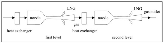
Figure 6.
Schematic diagram of the liquefaction process of a two-stage nozzle.
- Pressure recovery ability
When using two-stage nozzles to liquefy natural gas, it is necessary to ensure that the pressure recovery process does not affect the condensation of natural gas. The shock waves generated during the recovery of pressure energy cannot enter the nozzle.
The pressure distribution in the nozzle and diffuser section under a different outlet pressure Pb in the diffuser section is shown in Figure 7. Figure 7 shows that as the outlet pressure of the expansion section increases, the shock wave gradually moves toward the nozzle. When Pb > 2.3 MPa, the shock wave will enter the nozzle expansion section from the diffuser section, which will affect the condensation of natural gas. Therefore, the inlet pressure of the second stage is set to 2.3 MPa.
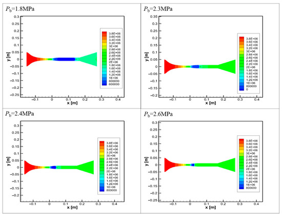
Figure 7.
Pressure distribution in nozzle and diffuser under different outlet pressures of diffuser.
When the outlet pressure of the diffuser section is 2.3 MPa, the temperature distribution in the first stage liquefaction unit is shown in Figure 8. Figure 8 shows that the temperature near the wall is relatively high, while the temperature at the central axis is relatively low, so the heat exchanger needs to be set for precooling before entering the second stage of the liquefaction device.
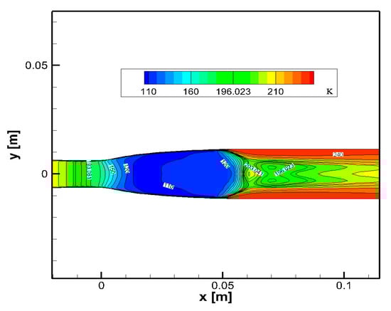
Figure 8.
The temperature distribution in the nozzle and diffuser under the back pressure of 2.3 MPa.
- 2.
- Analysis of liquefaction results
The humidity distribution in the nozzle of the first and second-stage liquefaction device is shown in Figure 9. The nozzle outlet humidity (Y1) in the first-stage liquefaction device is 0.041. The outlet humidity (Y2) of the nozzle in the second-stage liquefaction device is 0.067. The two-stage nozzle humidity (Y) is calculated by Equation (18).
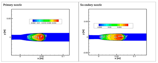
Figure 9.
Humidity distribution in two-stage nozzle.
According to Equation (18), Y is 0.105, which is 56.09% higher than the first level. Compared with the second level, the increase is 56.7%. Compared with the single-stage nozzle liquefaction device, the two-stage nozzle liquefaction device can obtain a better natural gas liquefaction effect.
6. Conclusions
- Based on the Euler-Euler method to establish the two-fluid model, the mathematical model of gas condensation in the Laval nozzle is established, and the control equations suitable for describing the complex flow process are constructed. A user-defined function (UDF) is written in C language for the source term of the control equation system, and a custom scalar (UDS) is applied to the transport equation, and the modeling is implemented by embedding Fluent. The developed model can accurately simulate the location and intensity of the occurrence of spontaneous gas condensation and has a strong ability to capture the excitation wave, which is in good agreement with the classical experimental data.
- At the same inlet pressure and pressure drop, compared with the throttle valve, the throttle valve can not liquefy the natural gas, and the temperature drop is lower than that of the supersonic cyclone separation device. This also shows that although the liquefaction rate of the supersonic cyclone separation device is not high, its performance is superior to that of the throttle valve. A combined method of adding an LNG condensation core and multistage nozzle is proposed to increase the liquefaction rate of natural gas in the nozzle. When the radius of the added condensation core is less than 1 × 10⁻⁹ m, the humidity change corresponding to each radius is larger. Meanwhile, the smaller the radius of the added condensation cores is, the more obvious the effect on the abatement of the condensation impulse wave is. The liquefaction rate increased by 56.09% compared with the first stage under the tandem condition. Compared with the second stage, the liquefaction rate increased by 56.7%.
- While the 3D Eulerian–Eulerian model shows predictive ability for supersonic swirling condensation, it has limitations that need to be addressed for industrial use. Assumptions like droplet homogeneity (no collision or breakup), ideal gas behavior (Dalton’s law at low pressure), and simplified near-wall treatment (wall functions) may not align with real multicomponent LNG dynamics. Future efforts should focus on developing multicomponent nucleation models calibrated with LNG experiments, incorporating droplet tracking to assess coalescence/breakup, optimizing cascade-stage heat recovery to reduce pre-cooling penalties, and validating supersaturation gradients and shock-droplet interactions via molecular dynamics simulations. Resolving these issues will help advance the technology from conceptualization to practical LNG liquefaction systems.
Author Contributions
Writing—original draft preparation, Y.T. and X.L.; writing—review and editing, Y.T. and H.Q.; software, Y.T. and H.H.; funding acquisition, X.L. All authors have read and agreed to the published version of the manuscript.
Funding
This work is funded by the Natural Science Foundation Projects of Chongqing City (No. CSTB2024NSCQ-MSX1103 and No. cstc2021jcyj-msxmX0978).
Data Availability Statement
The original contributions presented in this study are included in the article. Further inquiries can be directed to the corresponding author.
Conflicts of Interest
The authors declare no conflicts of interest.
References
- Fadiran, G.; Adebusuyi, A.T.; Fadiran, D. Natural gas consumption and economic growth: Evidence from selected natural gas vehicle markets in Europe. Energy 2019, 169, 467–477. [Google Scholar] [CrossRef]
- Yin, Q. Application of Propane-Assisted Refrigeration Energy Saving Process in Natural Gas Cryogenic Treatment. Chem. Equip. Pipelines 2004, 25, 45–46. [Google Scholar]
- Liu, W.; Hu, D. Research Status of Gas Wave Refrigeration Technology. Refrigeration 2002, 21, 19–24. [Google Scholar]
- Che, Y. Comparative Analysis of Propane-Assisted Refrigeration Process Flow of Double-Stage Expansion and Single-Stage Expansion in Natural Gas Cryogenic Treatment Unit. Eng. Technol. 2016, 5, 212. Available online: https://www.cqvip.com/doc/journal/2010237051978385408?sign=0fd16e3d32fefb6b12e2664707b6ec23cc6873e7a8a04c6e4e5a71c3ab8d33b2&expireTime=1784783461633&resourceId=2010237051978385408 (accessed on 28 July 2025).
- Gao, X.-G.; Ji, W.-A.; Liu, Q.; Peng, S.; Wang, T.-T.; Lei, M. Supersonic Separation Technology and Its Application in Gas Field Surface Engineering. Oil Gas Chem. Ind. 2011, 40, 42–46. [Google Scholar]
- Haghighi, M.; Hawboldt, K.A.; Abdi, M.A. Supersonic gas separators: Review of latest developments. J. Nat. Gas Sci. Eng. 2015, 27, 109–121. [Google Scholar] [CrossRef]
- Garrett, R.L. Supersonic Flow Separator with Film Flow Collector. US 3,528,217, 15 September 1970. [Google Scholar]
- Song, J. Application of Nozzle Supersonic Separation Technology in Gas Dehydration. Ph.D. Thesis, Beijing University of Chemical Technology, Beijing, China, 2010. [Google Scholar]
- Zhu, L. Study on Flow Field Characteristics of a New Supersonic Swirl Separation Tube. Master’s Thesis, Southwest Petroleum University, Chengdu, China, 2015. [Google Scholar]
- Liang, B. Analysis on Improvement of Natural Gas Dewatering Process in Supersonic Gas–Liquid Separator. Henan Sci. Technol. 2014, 2, 114. Available online: https://kns.cnki.net/kcms2/article/abstract?v=5ykJdPmCibL5Cq0nQnC-k3uBc2E7PmDUHqAPGu19qL_lAYNX81aXRUStAF-JCM5k5AMBlbM23UJOj1275C9p4paeO7yYvEVUOramUgUTxgK1AfaF2pwfIXwehWlQWqV5U3XWnOy9tYn-TW5Phnnag2UjUTu5vCWS&uniplatform=NZKPT (accessed on 28 July 2025).
- Zou, Y.; Zhao, J.; Liu, B.; Song, M.; Xu, A. Supersonic separation technology in natural gas processing units. Oil Gas Field Surf. Eng. 2014, 33, 76. [Google Scholar]
- Shooshtari, R.S.A. Numerical Investigation of Water Droplets Trajectories during Natural Gas Dehydration inside Supersonic Separator. J. Nat. Gas Sci. Eng. 2018, 54, 131–142. [Google Scholar] [CrossRef]
- Ma, Z.; Wang, L.; Zhang, J.; Zhang, P.; Chen, G.; Dong, J.; Gao, F.; Li, J. Influence of soluble particles on the heterogeneous coalescence nucleation and separation process in a supersonic cyclone separator. Chem. Eng. Sci. 2024, 291, 119908. [Google Scholar] [CrossRef]
- Mazen, A.A. Preliminary design and simulation of an innovative Rotary Supersonic Nozzles Expander apparatus for natural gas liquefaction and general refrigeration processes. Appl. Therm. Eng. 2023, 222, 119755. [Google Scholar]
- Bian, J.; Cao, X.; Yang, W.; Song, X.; Xiang, C.; Gao, S. Condensation characteristics of natural gas in the supersonic liquefaction process. Energy 2019, 168, 99–110. [Google Scholar] [CrossRef]
- Bian, J.; Cao, X.; Teng, L.; Sun, Y.; Gao, S. Effects of inlet parameters on the supersonic condensation and swirling characteristics of binary natural gas mixture. Energy 2019, 188, 116082. [Google Scholar] [CrossRef]
- Ding, H.; Zhang, Y.; Yang, Y.; Wen, C. A modified Euler-Lagrange-Euler approach for modeling homogeneous and heterogeneous condensing droplets and films in supersonic flows. Int. J. Heat Mass Transf. 2023, 200, 123537. [Google Scholar] [CrossRef]
- Wen, C.; Cao, X.; Yang, Y.; Li, W. Numerical simulation of natural gas flows in diffusers for supersonic separators. Energy 2012, 37, 195–200. [Google Scholar] [CrossRef]
- Shooshtari, R.S.; Shahsavand, A. Reliable prediction of condensation rates for purification of natural gas via supersonic separators. Sep. Purif. Technol. 2013, 116, 458–470. [Google Scholar] [CrossRef]
- Xu, W.; Peng, B.; Liang, D.; Yu, S.; Yu, Z. CFD simulation of the influence of swirl intensity on entropy production for wet steam flow in supersonic dehydration. Chem. Eng. Process. Process. Intensif. 2024, 203, 109893. [Google Scholar] [CrossRef]
- Duan, X.; Zhang, Z.; Zhao, Z.; Liu, Y.; Gong, L.; Cao, X.; Bian, J. Supersonic expansion and condensation characteristics of hydrogen gas under different temperature conditions. Chin. J. Chem. Eng. 2024, 69, 220–226. [Google Scholar] [CrossRef]
- Yang, Y.; Cao, X.; Guo, D.; Cao, H.; Bian, J.; Han, C.; Jiang, W.; Liu, Z.; Liu, Y.; Dou, Z.; et al. Influence of Shock Wave/Boundary Layer Interaction on Condensation Flow and Energy Recovery in Supersonic Nozzle. Energy 2023, 263, 125662. [Google Scholar]
- Wang, S.; Wang, C.; Ding, H.; Li, S. Evaluation of dynamic behaviors in varied swirling flows for high-pressure offshore natural gas supersonic dehydration. Energy 2024, 300, 131498. [Google Scholar] [CrossRef]
- Wyslouzil, B.E.; Heath, C.H.; Cheung, J.L.; Wilemski, G. Binary condensation in a supersonic nozzle. J. Chem. Phys. 2000, 113, 7317–7329. [Google Scholar] [CrossRef]


Disclaimer/Publisher’s Note: The statements, opinions and data contained in all publications are solely those of the individual author(s) and contributor(s) and not of MDPI and/or the editor(s). MDPI and/or the editor(s) disclaim responsibility for any injury to people or property resulting from any ideas, methods, instructions or products referred to in the content. |
© 2025 by the authors. Licensee MDPI, Basel, Switzerland. This article is an open access article distributed under the terms and conditions of the Creative Commons Attribution (CC BY) license (https://creativecommons.org/licenses/by/4.0/).