Article

Optimization of Machining Efficiency of Aluminum Honeycomb Structures by Hybrid Milling Assisted by Longitudinal Ultrasonic Vibrations

1
Laboratoire de Sciences de l’Ingénieur, Equipe Lean Manufacturing et Modélisation Mécanique, Ecole Nationale des Sciences Appliquées, Oujda 60000, Morocco
2
Centre de Recherche (CREHEIO) de L’Ecole des Hautes Etudes d’Ingénierie, Equipe de Production Intégrée, Oujda 60000, Morocco
3
Laboratoire d’Energétique et de Mécanique Théorique et Appliquée, Ecole des Mines de Nancy, Université de Lorraine, F-88100 Saint Dié Des Vosges, France
4
Laboratory of Energetics (LE), Faculty of Sciences, Abdelmalek Essaadi University, Tetouan 93000, Morocco
*
Author to whom correspondence should be addressed.
Processes 2025, 13(8), 2348; https://doi.org/10.3390/pr13082348
Submission received: 30 June 2025 / Revised: 19 July 2025 / Accepted: 21 July 2025 / Published: 23 July 2025

Abstract

The use of aluminum honeycomb structures is fast expanding in advanced sectors such as the aeronautics, aerospace, marine, and automotive industries. However, processing these structures represents a major challenge for producing parts that meet the strict standards. To address this issue, an innovative manufacturing method using longitudinal ultrasonic vibration-assisted cutting, combined with a CDZ10 hybrid cutting tool, was developed to optimize the efficiency of traditional machining processes. To this end, a 3D numerical model was developed using the finite element method and Abaqus/Explicit 2017 software to simulate the complex interactions among the cutting tool and the thin walls of the structures. This model was validated by experimental tests, allowing the study of the influence of milling conditions such as feed rate, cutting angle, and vibration amplitude. The numerical results revealed that the hybrid technology significantly reduces the cutting force components, with a decrease ranging from 10% to 42%. In addition, it improves cutting quality by reducing plastic deformation and cell wall tearing, which prevents the formation of chips clumps on the tool edges, thus avoiding early wear of the tool. These outcomes offer new insights into optimizing industrial processes, particularly in fields with stringent precision and performance demands, like the aerospace sector.

1. Introduction

Aluminum honeycomb core sandwich structures represent an advanced category of composite materials that are widely used in high-tech industrial sectors, such as the aerospace and automotive industries [1,2]. These materials are preferred for the manufacture of specific components, including aircraft fins, helicopter rotors, and satellite power compartments, due to their exceptional combination of lightness, rigidity, and mechanical strength [3,4,5,6,7]. This performance is made possible by the unique structure of the honeycomb core, which optimizes both the mechanical properties and the performance characteristics of the materials under extreme conditions. The structure of these materials, composed of a honeycomb core between two thin layers, offers superior rigidity compared to conventional materials. However, the geometric complexity of honeycomb cores and the defects generated during machining pose a major challenge for their integration into industrial processes, requiring high-precision machining [8]. However, due to the low rigidity of thin walls, defects such as deformations and burrs can often occur during machining [9,10,11]. To address these challenges, an innovative cryogenic freezing fixation method was used, allowing the cells to be stabilized and reducing vibrations associated with the machining process [12]. In this context, Wang et al. [13,14] conducted experiments on cryogenic milling with freeze fixation, demonstrating a substantial reduction in surface defects. This study was complemented by extensive experiments aimed at elucidating the physical mechanisms involved in chip formation, as well as the complex interactions among tool edge and the cell walls [15]. The research of Wang et al. focuses on the study of cutting forces during machining of aluminum honeycomb materials, examining the influence of parameters such as cutting speed, feed rate, and depth of cut. Through theoretical modeling and experimental tests, they highlighted the crucial impact of the geometry of the honeycomb, in particular the density and orientation of the cells, which directly affect the stability of machining, as well as the quality of the parts obtained [5]. The research conducted by Zarrouk et al. [16]. focuses on modeling conventional machining of aluminum honeycomb structures. They have developed numerical models to simulate the cutting forces and deformation phenomena associated with milling these complex materials. Their study highlights the influence of cutting conditions and geometric parameters on cutting performance. The results obtained underline that model accuracy is essential to optimize machining and reduce defects. Conventional machining has limitations, including high cutting forces and poor surface quality, even under optimal conditions. To overcome these constraints, researchers explored ultrasonic vibration-assisted machining, a method that applies high-frequency vibrations to the cutting tool, thereby reducing cutting forces and improving surface quality. Several experimental studies have been carried out to evaluate the impact of vibrations on the machining process, especially for materials that are challenging to machine, like aluminum alloys and composite materials. The study by Sun et al. [17] analyzes the deformation of cell walls during ultrasonic cutting of aluminum honeycomb core with a straight-blade knife, using an experimentally validated finite element model. The blade tilt angle and ultrasonic amplitude influence cutting forces and reduce wall deformation, thus improving cutting quality. A study conducted by Kuo et al. [18] investigated the impact of tool geometries, ultrasonic vibrations, and cutting speed on forces, tool wear, surface integrity, and internal damage in the machining of glass fiber honeycomb cores. While ultrasonic vibrations reduce cracks, high cutting speeds exacerbate internal damage, and although helical cutters cause less wear than straight cutters, high speeds and amplitudes can lead to severe cracks. Ultrasonic cutting stands out as an advanced technique, significantly reducing cutting forces and imperfections while optimizing process efficiency [19,20]. This process combines the rotation of a disc cutter with high-frequency longitudinal ultrasonic vibrations. The feasibility of this method has been validated by previous research [21,22], using both numerical simulations and experimental tests, and showed increased preservation of the hexagonal structure as well as improved machining quality. However, these studies have mainly focused on macroscopic effects and large-scale applications, neglecting the microscopic mechanism of ultrasonic cell wall cutting. Few comprehensive studies have explored hybrid ultrasonic machining (HUSVAM) applied to aluminum honeycomb structures, especially with respect to key parameters such as material accumulation, cutting force, spatial components, and surface finish. Grinding process optimization frequently relies on experimental tests, which are often time-consuming and costly. Therefore, numerical modeling is emerging as a key solution, allowing the simulation of various configurations and different cutting conditions at low cost [23]. Despite its potential, the milling of aluminum honeycomb cores with HUSVAM technology has not been thoroughly studied, particularly regarding the cutting force, spatial components, surface quality, and chip accumulation. With this perspective, a three-dimensional model based on the finite element method (FEM) is proposed to simulate the machining of aluminum honeycomb cores. This model presents the application of longitudinal ultrasonic vibrations on a CDZ10 combined cutting tool, designed with Abaqus/Explicit software. The primary aim of this study is to conduct a thorough analysis of the machining process mechanism, the surface quality obtained, and the accumulation of chips in front of the tool, as well as the cutting force and its components in the three directions, as a function of the feed rate and the cutting angle. The obtained results reveal that surface quality can be significantly improved, while cutting forces are reduced, thus contributing to overall optimization of the machining process.

2. Materials and Methods

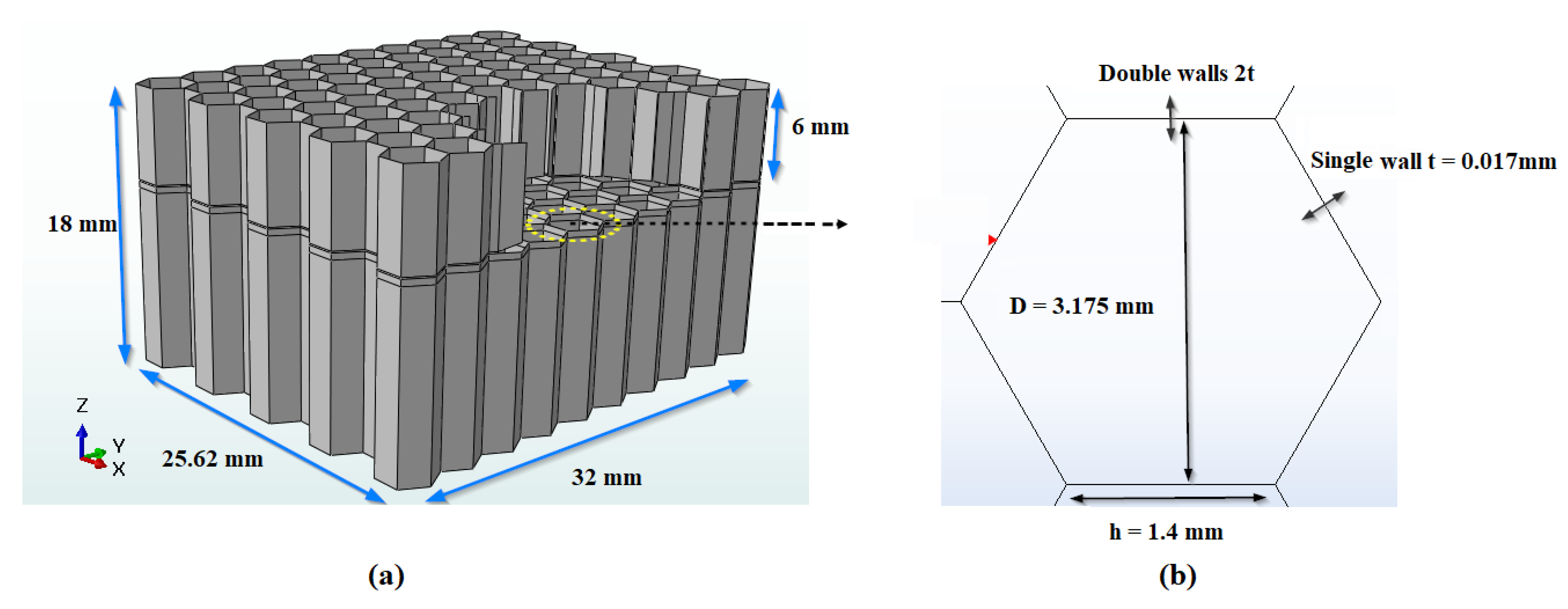
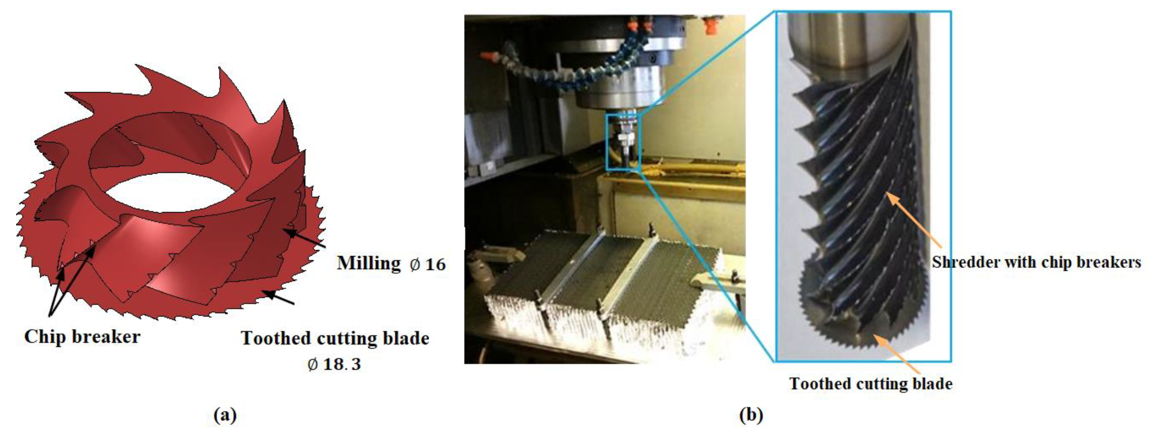
2.1. The Cutting Tool and the Structure Studied

This experimental study focused on conventional machining of 5056 aluminum honeycomb structures, a material appreciated for its excellent compromise between lightness and strength, suitable for applications requiring high mechanical performance. The tests were carried out on a RÖDERS 600 high-speed machining center, recognized for its precision and its ability to reproduce strict industrial conditions, following protocols defined by the University of Lorraine, France [24]. To ensure the accuracy of the results, the tests were performed according to specific machining standards. The Taguchi method was used to optimize the cutting parameters and prioritize the factors influencing the machinability of the material. Furthermore, the piezoelectric dynamometer, with sensors such as the Kistler 9129AA, made it possible to measure cutting forces and analyze the stability of machining operations. Furthermore, characterization tools, such as scanning electron microscopes and 3D profilometers, were employed to accurately assess the quality of the machined surfaces. The scope of this study was expanded to include analysis of longitudinal ultrasonic vibrations, allowing a better understanding of their impact on the structure, to evaluate their effects on the performance and stability of the material, and to detect possible structural anomalies or weaknesses. This facilitated optimization of the machining parameters and prevention of failures. The machined structure, with a density of 49 kg/m3, has specific geometric dimensions, illustrated in Figure 1, consisting of 10 cell rows in width and 19 in length (Figure 1a). The mechanical properties of 5056 aluminum, shown in Table 1, are influenced by the geometry of the hexagonal cells, affecting the overall density of the structure (Figure 1b).
Machining 5056 aluminum honeycomb structures, which are widely used in the aerospace industry for their exceptional mechanical properties, requires specialized cutting tools to achieve high surface quality and precision while withstanding significant mechanical constraints. In this context, the CZD10 tool, a prototype designed by EVATEC Tools, was utilized [24]. This tool features a circular cutter with a cylindrical body measuring 16 mm in diameter, fitted with ten chip-breaking helices. It also includes a conical, tungsten carbide-toothed disc with a diameter of 18.3 mm and 55 teeth. The disc has a cutting angle of 0° and a clearance angle of 2.5° (Figure 2).

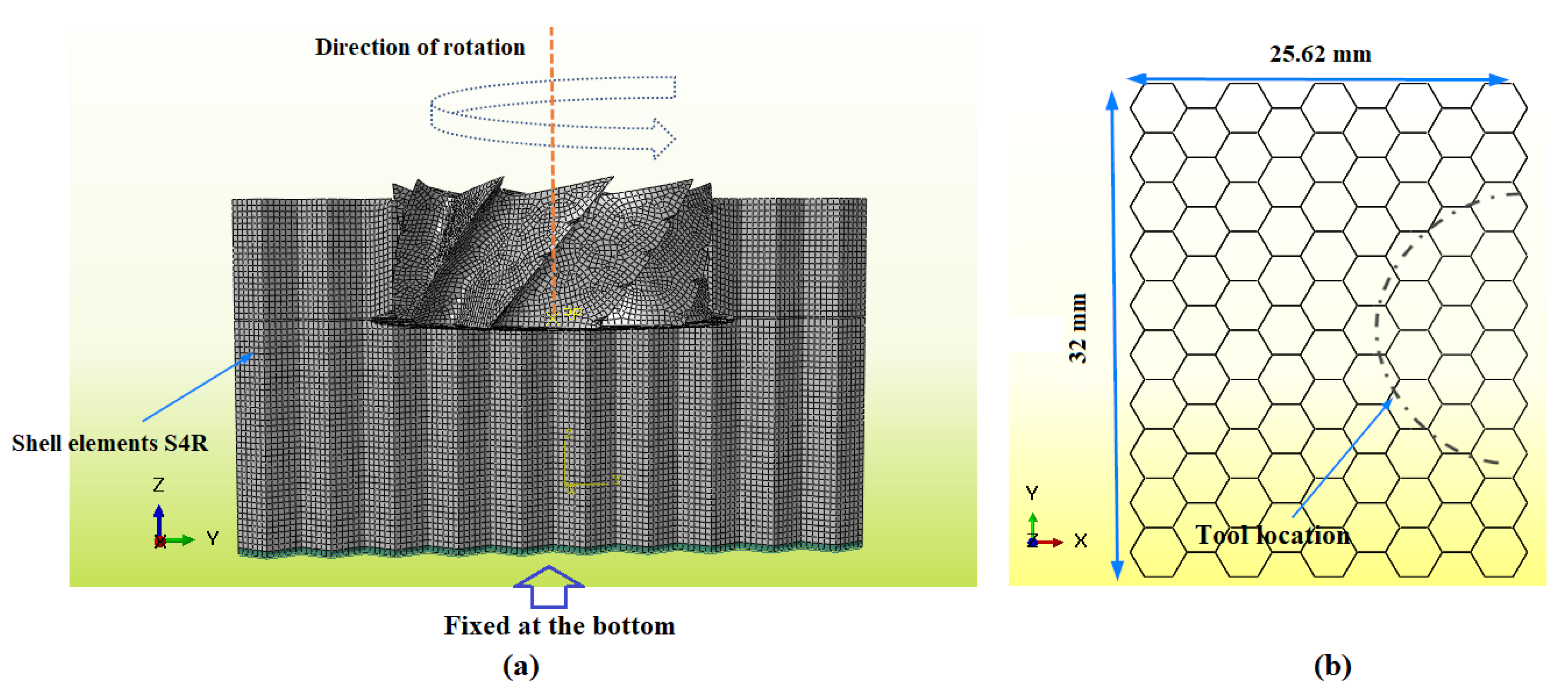
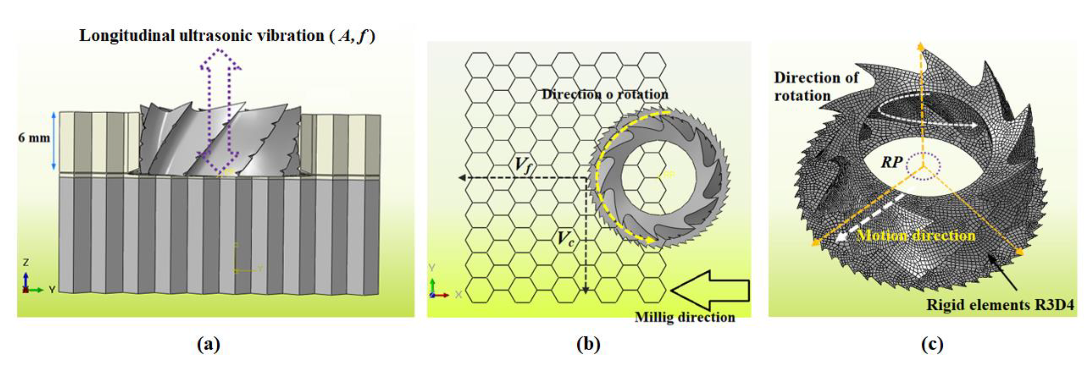
2.2. Presentation of Experimental and Numerical Methodologies

This article emphasizes modeling of the milling process of an aluminum honeycomb structure, a ductile material commonly used in aeronautical applications. This study begins with validation of a numerical model dedicated to conventional machining before integrating a hybrid technique involving longitudinal vibrations. The simulation is conducted using a 3D model developed by Abaqus/Explicit (6.17), allowing the complex interactions among the tool and the thin walls of the honeycomb structure to be accurately captured. This modeling provides a detailed analysis of mechanical behavior during the machining operation. The structure considered is made up of hexagonal cells whose walls, single or double, have respective thicknesses of 0.017 mm and 0.034 mm, in agreement with the characteristics of the real material (Figure 1). For modeling purposes, thin walls are discretized using four-node S4R quadrilateral shell elements with reduced integration, thus ensuring a relevant compromise between geometric fidelity and numerical efficiency (Figure 3a). Due to the low mechanical stresses experienced by the cutting tool compared to the deformations of the thin walls of the honeycomb structure, the tool is modeled as a rigid body and discretized with four-noded R3D4 rigid quadrilateral elements (Figure 4c). A regular mesh of 0.3 mm was chosen, offering a best compromise among the accuracy of the results and the computational time, with approximately 23,539 elements, thus ensuring the numerical model robustness. The simulation takes into account two types of interactions at the level of contact between the cutting tool and the machined structure: direct contact between the cutter and the alveolar walls during milling and interactions among the walls themselves, induced by their bending after the passage of the tool, as well as contacts among the chips and the unmachined surfaces. This fine modeling of contact and friction phenomena contributes to faithful representation of the process while ensuring the numerical stability of the simulation. A dynamic friction coefficient of 0.12 was introduced to take into account the reduction in contact forces linked to the effect of longitudinal vibrations, which limit direct contact between the tool and the material. This approach allows for more faithful modeling of the machining process, integrating the effects of ultrasonic vibrations as well as the localized nature of the interaction among the tool teeth and the thin walls of the workpiece. To guarantee genuine interaction among the tool and the workpiece, an initial integration phase is approved, considering the unique geometric properties of the cutter and the cellular structure of the honeycomb core (Figure 3b). The boundary conditions applied to the tool/part system were directly adopted according to the experimental setup. The part is held in place using two fixing rods, modeled by symmetry conditions imposed on the alveolar walls around the Y plane (Uy = URx = URz = 0), prohibiting any movement in this direction. Similarly, symmetry is imposed with respect to the X plane (Ux = URy = URz = 0) on the opposite surface. Furthermore, the lower face of the part is rigorously fixed to the machining table, preventing any degree of freedom. This constraint is numerically translated by complete embedding (Ux = Uy = Uz = URx = URy = URz = 0), in accordance with the configuration represented in Figure 3a.
The hybrid ultrasonic vibration-assisted milling (HUSVAM) process combines traditional rotary milling with the application of high-frequency ultrasonic vibrations, typically above 20 kHz, oriented perpendicular to the cutting surface. This approach is based on the combination of three synchronous movements: linear movement of the tool along the OX axis at a feed rate Vf, rotation of the cutter around the OZ axis at a rotation rate n, and ultrasonic longitudinal oscillation along the same axis, inducing sinusoidal movement (see Figure 4a,b). In order to precisely model this behavior in the numerical simulation, a reference point (RP) is defined on the tool rotation axis (Figure 4c). This point allows you to specify the cutting conditions and calculate the forces generated during machining. The following equations describe the tool path as a function of time, incorporating all three motion components, and yield the global coordinates.
V x = V c cos 2 π n 60 t + V f
V y = V c sin 2 π n 60 t
V z = A cos 2 π f t
The parameters used in the analysis are defined as follows: A corresponds to the amplitude of ultrasonic vibrations; Vc, Vf, and n denote the cutting speed, feed rate, and spindle rotation speed, respectively; t represents the time; and f represents the vibration frequency. The frequency was systematically maintained at 22.05 kHz for all numerical simulations, thus ensuring constant experimental conditions.

3. Fundamental Material Properties, Degradation Processes, and Failure Criteria

In the context of numerical modeling, the aluminum honeycomb core is represented by an assembly of aluminum sheets discretized in the form of shell elements. These sheets are considered a homogeneous material, whose mechanical behavior is assumed to correspond to that of standard aluminum. The latter is classically modeled using a thermo-visco-plastic constitutive law, and in particular by the Johnson–Cook criterion (equation 4), widely adopted for its capacity to represent the coupled effects of work hardening, strain rate, and temperature. This model thus makes it possible to precisely describe the thermal softening of the material under dynamic stress. The mathematical expression of this law is given below [25,26]:
σ ¯ = A + B ε ¯ n [ 1 + C l n ( ε ¯ ˙ ε ¯ ˙ 0 ) ]   [ 1     ( T T 0 T f T 0 ) n ]
The constants A, B, n, C, and m, specific to the machined material, are determined experimentally. The variable ε ¯ ˙ 0 corresponds to a reference strain rate, while Tf and T0 represent the melting temperature and the reference temperature of the material, respectively. The honeycomb core used in the modeling is made of 5056 aluminum, the properties of which are summarized in Table 1 [27,28].
The values of the Johnson–Cook parameters, which are used in numerical modeling and come from the literature, are precisely provided in Table 2 [29].
In this study, the walls of aluminum honeycomb cores are modeled using thin shell elements. The cutting method adopted has a particularity: at each rotation of the tool, the teeth only come into contact with the thin walls at localized points, which restricts the contact surface among the tool and the workpiece. In addition to the Johnson–Cook constitutive law, a specific damage model is applied to aluminum walls. The failure criterion, based on the Johnson–Cook model, takes into account the progressive evolution of damage during the process. Failure is considered to have occurred when the damage parameter reaches a threshold value of 1. This parameter is calculated using the following formula:
d   =   ε ε f
In this equation, Δε corresponds to the increment of the equivalent plastic strain, and ε to the strain equivalent to rupture. The latter is calculated based on several variables, including strain rate, temperature, pressure, and equivalent stress. The formula for determining εf is as follows:
ε f = [ d 1 + d 2 ε [ d 3 σ m σ ¯ ] ]   [ 1   +   d 4 l n ( ε ¯ ˙ ε ¯ ˙ 0 ) ]   [ 1     d 5 ( T T 0 T f T 0 ) ]
The damage coefficients d1, d2, d3, d4, and d5 are constants characteristic of the material studied. The hydrostatic pressure is denoted by σm, while σ ¯ represents the equivalent stress according to the von Mises criterion [30,31,32,33]. For this simulation, the damage parameters chosen are those proposed by Zheng et al. [34], with details shown in Table 3.
The degradation of material stiffness is modeled by linear progression of damage. When the effective plastic deformation of an element reaches a determined threshold, the stiffness of the material is considered to be completely lost, thus leading to removal of this element from the simulation. In order to realistically simulate feature removal during milling, while taking into account the specific mechanical properties of aluminum, the maximum increase in effective plastic deformation after damage initiation is limited to 1%. This constraint makes it possible to better reflect the observed behavior of the material.

4. Cutting Force and Its Components

Cutting force analysis is essential to assess both the quality of the machining process and the overall performance of the machine tool. These efforts directly influence the sizing of mechanical elements, the prediction of deformations of machined parts, and the study of chip behavior, by integrating the mechanical properties of the material. The calculation of cutting forces is carried out by applying the method specified in [35,36].
F x = 1 t 2 t 1 t 1 t 2 F C X d t
F y = 1 t 2 t 1 t 1 t 2 F C Y d t
F z = 1 t 2 t 1 t 1 t 2 F C Z d t
F A v g = F x 2 + F y 2 + F z 2

5. Results and Discussion

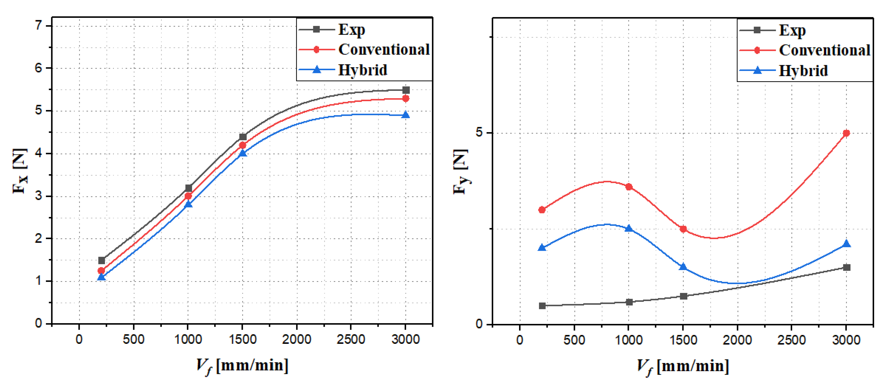
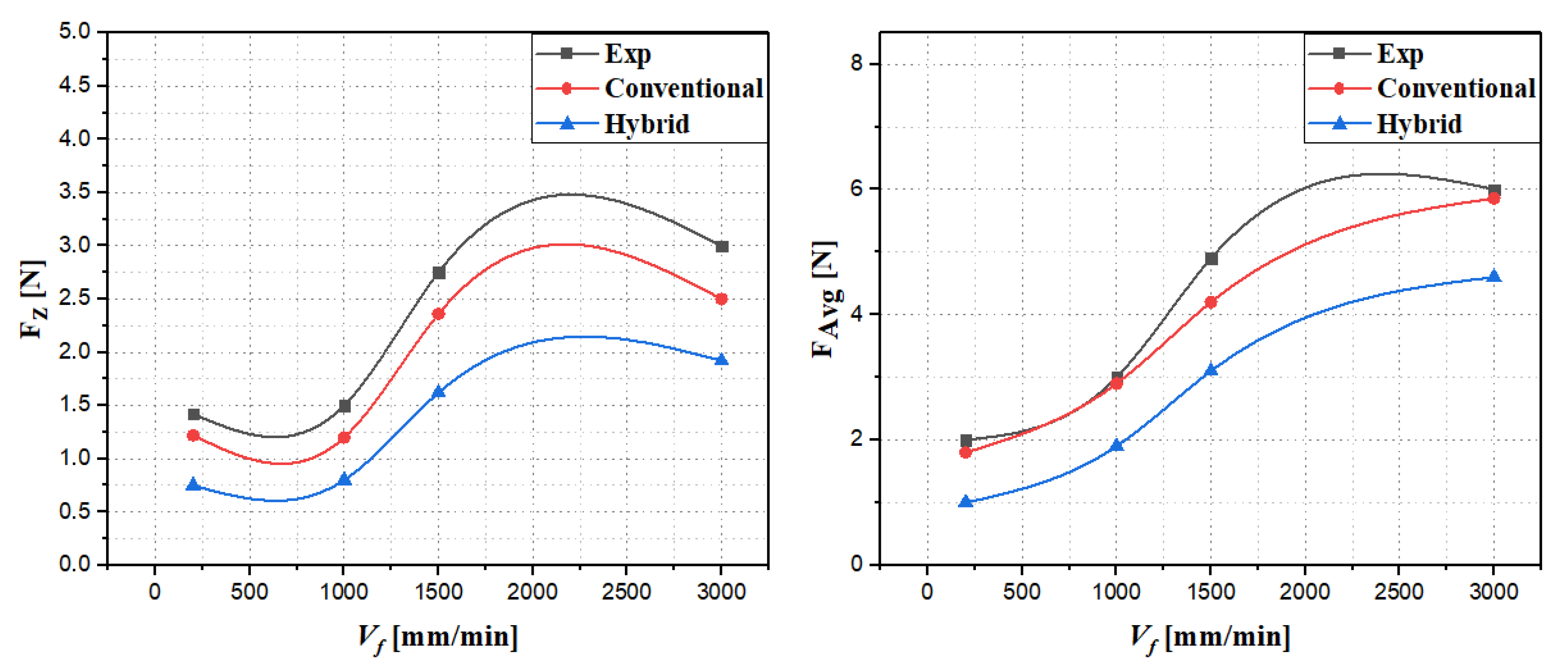
5.1. Comparative Study of the Influence of Feed Rate on Cutting Forces in Hybrid and Conventional Cutting

This paragraph presents a comparative analysis of the performances of conventional milling and hybrid machining, the latter integrating longitudinal ultrasonic vibrations applied to an aluminum honeycomb structure, through numerical simulations. Validation of the numerical model was carried out by comparing the results of conventional machining simulations with experimental data obtained under identical conditions, thus guaranteeing the accuracy and reliability of the model [24]. Based on this validation, additional simulations were carried out to study the influence of the feed rate on the cutting force and its spatial components, for both processes, in the context of cutting the aluminum honeycomb structure. To do so, the cutting parameters were kept constant, with a rotation speed of 2000 rpm and a vibration amplitude of 25 µm. Figure 5 and Figure 6 illustrate the behavioral differences between conventional and hybrid machining, depending on feed rate variations.
Comparative analyses indicate that the two machining processes studied, namely conventional machining and hybrid machining assisted by ultrasonic vibrations, present a similar evolution of the overall cutting force and its components, in full agreement with the experimental results. Specifically, comparison of the main components of the cutting force, such as Fx and Fz, shows a noteworthy correspondence among the results of the numerical simulations and the experimental data, with observed deviations not exceeding 16%. On the other hand, the Fy component does not correspond to the experimental results, due to the removal of damaged elements and the loss of contact between the material and the cutting tool. Also, it was observed that the Fy component of the cutting force is not stable between feed rates of 1000 and 3000 mm/min: the forces decrease from 1000 to 1500 mm/min, then increase from 1500 to 3000 mm/min. This variation is related to the strong dependence of the elastic return force of the walls on the clearance face. When the element reaches the breaking point, it is withdrawn, resulting in a loss of contact between the material and the tool, which temporarily reduces the cutting forces. However, the spring back of the uncut walls generates resistance in the opposite direction of tool rotation, which ultimately increases the Fy component. The simulation results show that the feed component Fx increases with feed rate in both machining modes, ranging from 1.4 N to 5.4 N in conventional mode, and being limited to 4.9 N in hybrid mode at a speed of 3000 mm/min, a reduction of approximately 10%. This decrease is due to the reduction in friction caused by micro-oscillations induced by ultrasonic vibrations, which reduce the effective contact between the material and the tool, thus limiting the values of the feed component Fx. The lateral force Fy varies between 2.5 N and 5 N in conventional machining, while in hybrid mode it is reduced, with a decrease of up to 42% at high feed rates. This improvement results from the combination of an optimized cutter with helices and ultrasonic vibrations, which promote chip evacuation and improve the stability of the material removal process, thus reducing forces perpendicular to the cutting path and mitigating stresses related to local variations in material properties. The vertical component Fz increases considerably with feed rate in conventional machining, reaching 2.5 N, while in hybrid mode it is limited to 2 N, a reduction of 20%. This gain results from ultrasonic vibrations, which reduce resistance to tool penetration and limit crushing of the aluminum cells, thus ensuring a cleaner, more precise, and controlled cut. Furthermore, it was found that the crushing component Fz is twice as large as the advance component Fx, which demonstrates increased resistance of the aluminum honeycomb structure to out-of-plane stresses [37]. The average force FAvg increases with feed rate, reaching 6 N in conventional machining and 4.6 N in hybrid mode at 3000 mm/min, a reduction of almost 25%. This reduction reflects an improvement in the energy efficiency of the process, thus reducing the mechanical work required and the thermal stresses on the tool. The analysis of this study highlights the effectiveness of the hybrid process for machining ductile metallic materials, with a reduction in cutting forces reaching up to 20%. This reduction in cutting forces contributes not only to significant improvement in cutting quality, but also to a significant extension of cutting tool life. The obtained results confirm the effectiveness of the process, as demonstrated by the experimental work of Sun et al., who reported similar results in the milling of aluminum honeycomb structures using a disc milling cutter [17]. Experimental validation of the numerical model shows good agreement with the experimental results, particularly for the force components Fx and Fz, thus validating its reliability. However, deviations in the Fy component indicate the need to improve modeling of dynamic phenomena and alignment effects. Despite these differences, the model provides a solid basis for optimization of process parameters and the development of advanced strategies for ultrasonic vibration-assisted hybrid machining.

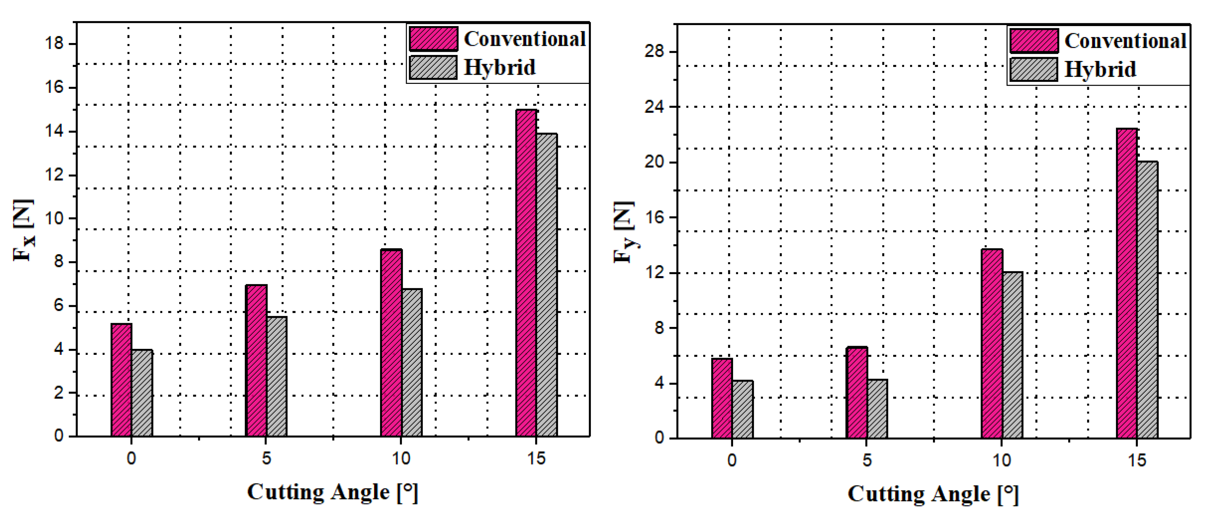
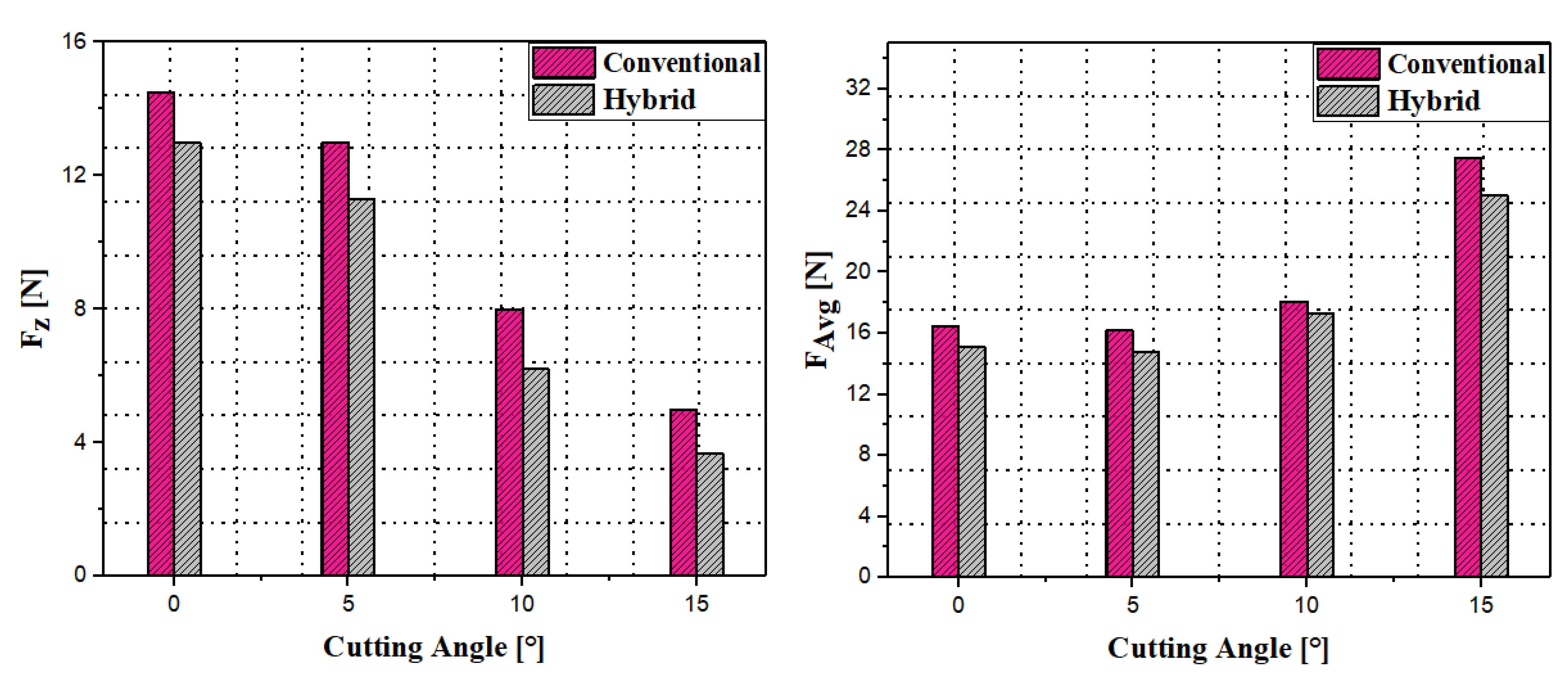
5.2. Impact of Cutting Angle on Cutting Force and Their Components in Hybrid and Conventional Machining

Machining aluminum honeycomb structures poses a major challenge due to their complex architecture and ductile properties, which complicate the control of local deformations, accentuate tool–material interactions, and accelerate tool wear. This makes it essential to optimize cutting conditions in order to preserve material integrity, improve surface finish, and extend tool life. In this context, a numerical study was approved to analyze the influence of cutting angle on cutting force and its components in the three spatial directions by comparing two processes: conventional machining and hybrid machining assisted by longitudinal ultrasonic vibrations. The simulations were approved under identical cutting conditions, with a constant rotation speed of 2000 rpm, a feed rate of 3000 mm/min, and a vibration amplitude fixed at 25 µm. The results, presented in Figure 7 and Figure 8, highlight the significant influence of cutting angle on cutting force and its components throughout machining of the aluminum core, while highlighting the advantages of the hybrid process.
In the X direction, the cutting force increases gradually with the rake angle for both methods. However, the conventional method shows a more marked increase, especially at the 15° angle. In contrast, the hybrid method exhibits a more moderate increase in cutting force, with overall lower values at all angles. This suggests that hybrid cutting optimizes the interaction of the tool with the material, probably through more efficient friction management, allowing for smoother and more controlled cutting. In the Y direction, for conventional cutting, the lateral force follows an increasing trend with increasing rake angle, with faster progression as the angle reaches 15°. The hybrid cut, on the other hand, shows smoother progression of this force, with a notable reduction in forces from 10°. This decrease in the hybrid method can be attributed to optimized resistance management perpendicular to the tool, which improves cutting stability. This means that the hybrid method requires less lateral force to maintain contact with the material, leading to a more controlled cutting process. In the Z direction, conventional cutting generates relatively high vertical forces at 0°, which decrease as the rake angle increases. Hybrid cutting, on the other hand, reduces these forces from 5° and maintains them at lower levels throughout the cutting process. This reduction can be explained by better chip evacuation, which reduces vertical resistance and optimizes cutting stability. The hybrid method consistently exhibits lower overall cutting forces. In the X direction, hybrid cutting reduces force by 15 to 30% compared to conventional cutting. In the Y direction, the reduction varies between 10 and 25%, with more pronounced decreases at higher angles. In the Z direction, the reduction is approximately 10 to 20%. These results show that hybrid cutting is more effectual, reducing overall forces and improving the efficiency of the cutting process. Ultrasonic vibrations play a vital role in reducing cutting forces without resorting to thermal effects. They facilitate interaction of the tool with the workpiece, thus reducing friction and refining tool penetration. This mechanism allows for smoother cutting and better chip evacuation and minimizes the risk of cracks or excessive deformation. It thus preserves the integrity of the material, particularly for aluminum honeycomb structures. From the data, it is evident that the optimal cutting angle for efficient cutting is between 10° and 15°. At these angles, cutting forces in both the feed and lateral directions are significantly reduced, improving cutting stability and extending tool life. Although an angle range between 5° and 10° also provides good performance for softer materials, a broader exploration of rake angles (from 0° to 20°) should be carried out to strengthen this conclusion and provide a more robust basis for selecting the optimal rake angle. Ultimately, hybrid cutting outperforms conventional cutting in terms of reducing cutting forces and refining process efficiency. The ideal cutting angles for achieving smooth and stable cuts are between 10° and 15°, although extension of the cutting angle range for further analysis is necessary to consolidate these results.

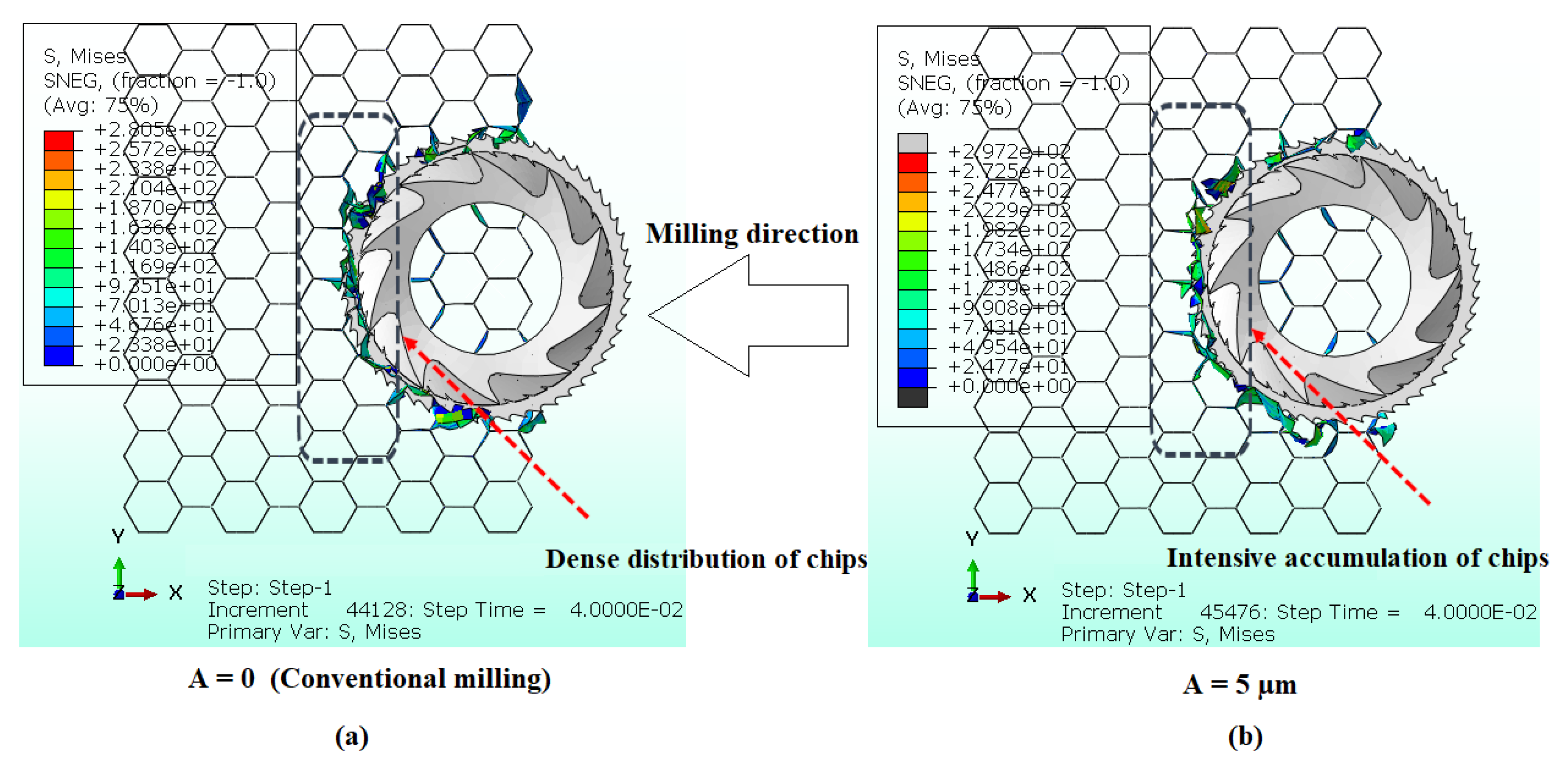
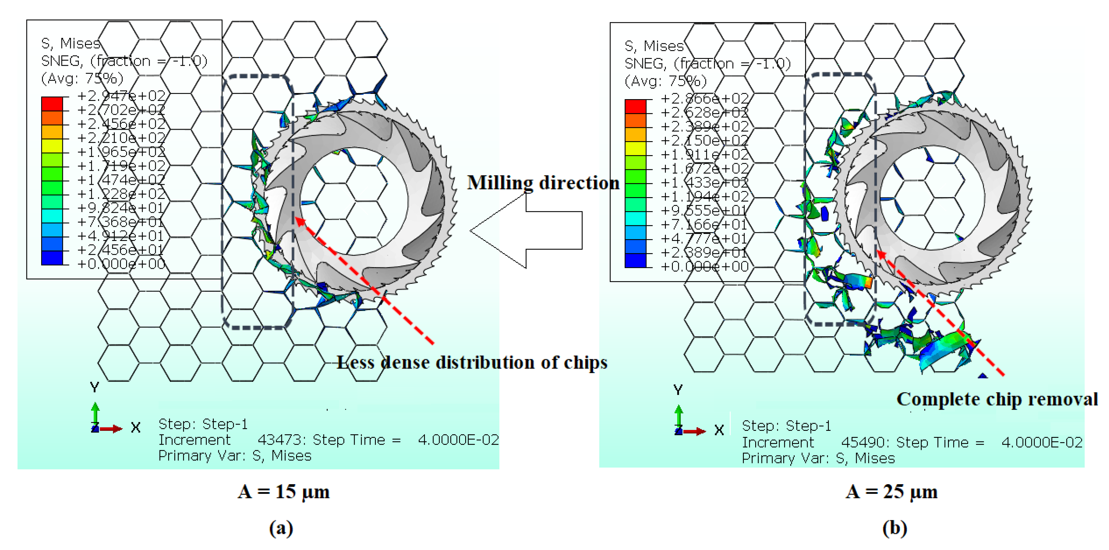
5.3. Analysis of Chip Distribution in Front of the Cutting Tool as a Function of the Amplitude of Ultrasonic Vibrations

The accumulation of chips in front of the cutting tool represents a major technical challenge in industrial machining, directly impacting the efficiency and precision of operations. In the absence of effective evacuation, these chips exert increased mechanical resistance, altering the dynamics of the tool and generating unwanted vibrations. These vibrations compromise process stability, deteriorate the quality of the machined surface, and accelerate tool wear, thus increasing costs and reducing equipment life. In this study, numerical simulations were conducted to evaluate the influence of vibration amplitude on chip accumulation in front of the cutting tool. Four distinct amplitudes were considered: 0 µm, 5 µm, 15 µm, and 25 µm. These simulations were approved under cutting conditions considered unfavorable for machining, namely a rotation speed of 200 rpm and a feed rate of 1500 mm/min. The obtained results are illustrated in Figure 9 and Figure 10.
The illustrations above highlight the phenomenon of chip accumulation during milling of an aluminum honeycomb structure, a material distinguished by its ductility and the thinness of its walls. Machining is carried out using a combination tool, consisting of a toothed knife to cut the walls and a milling cutter to fragment and shred the generated chips. However, the ductility of aluminum limits the effectiveness of the chip fragmentation and grinding process, and chips tend to accumulate in front of the tool. Indeed, cutting assisted by ultrasonic vibrations plays a crucial role in managing chip accumulation. In the absence of vibrations, i.e., with zero amplitude, the material deforms mainly plastically, which leads to the formation of long, adherent chips that accumulate in front of the cutter. This accumulation generates high local mechanical stresses and significant friction, thus complicating chip fragmentation. This increases the forces exerted on the tool, increases the risk of jamming, and accelerates premature tool wear. The introduction of a low-amplitude vibration of approximately 5 µm causes dynamic agitation in the cutting zone, which promotes increased chip accumulation in front of the tool. However, this amplitude remains insufficient to cause effective chip breakage. The generated cyclic stresses increase dynamic stresses without allowing optimal chipping, thus aggravating chip accumulation and the risk of jamming. On the other hand, for an intermediate amplitude of approximately 15 µm, vibrations create cyclic mechanical stresses sufficiently high to induce a local fatigue phenomenon in the ductile material. This fatigue facilitates chip breakage, particularly chip length and adhesion, thus allowing better management of accumulation. In this way, the cutter manages to fragment the chips more efficiently, facilitating their evacuation and limiting their accumulation. From a mechanical point of view, vibrations promote chip breakage while optimizing stress distribution in the cutting zone. At higher amplitudes, the vibration energy becomes intense enough to cause rapid and complete chip breakage, thus preventing chip accumulation in front of the tool. This reduction in friction, combined with better management of mechanical constraints, significantly reduces the forces applied to the cutter. The result is optimization of cutting efficiency, reduction in tool wear, and improvement in the quality of the surface.

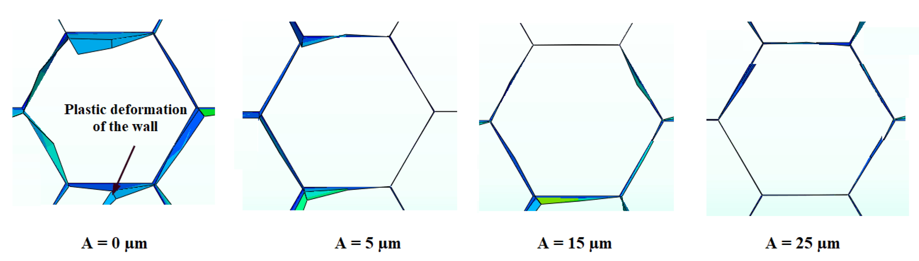
5.4. Analysis of Machined Surface Quality as a Function of Ultrasonic Vibration Amplitude

The quality of the machined surface of the aluminum honeycomb core is of crucial importance in the manufacture of sandwich structures. Precise optimization of this surface is essential to ensure the mechanical strength and durability of the materials in various industrial applications. Machining imperfections that can occur in aluminum structures generally manifest themselves in several forms, such as burrs, thin-wall deformations, or poorly detached chips. These imperfections, which can appear at diverse phases of the machining procedure, directly influence the final quality of the workpiece. It is thus essential to carry out an in-depth study in order to improve manufacturing conditions and minimize the appearance of these defects as much as possible. For this purpose, numerical simulations were carried out to analyze the impact of the vibration amplitude, varying from 0 to 25 µm, on the quality of the machined surface. These tests were approved under constant cutting conditions, with a feed rate of 3000 mm/min and a spindle speed of 2000 rpm. The resulting defects were then identified by visual inspection, as shown in Figure 11.
The primary outcomes of this study reveal progressive development in surface quality as a function of ultrasonic vibration amplitude. This trend reveals a significant correlation between vibration intensity and finish quality, suggesting the potential benefits of integrating ultrasonic vibrations into the milling processes. Furthermore, numerical simulations have shown that the major machining defects of aluminum honeycomb core are mainly associated with plastic deformation of the thin walls. However, the numerical model was unable to simulate the formation of burrs, the excess material frequently observed on cell walls. This limitation results from the fact that the modeling is based on S4R shell elements without thickness, which limits the ability to reproduce this type of defect. At low spindle speeds, the cutting tool has difficulty exerting adequate force on the thin walls of the ductile material, which significantly increases the risk of plastic deformation, although this deformation does not usually lead to fracture. In this context, the integration of ultrasonic vibrations into the machining procedure is a particularly effective solution. Indeed, these high-frequency vibrations reduce continuous contact between the tool and thin surfaces, resulting in a significant reduction in friction. This reduction in mechanical interactions promotes better heat dissipation in the cutting zone, thus limiting local heat concentrations that could damage the part. The ductility of the material is thus reduced, which optimizes the quality of the cut. Mechanically, the dynamic effect of ultrasonic vibrations generates a rapid succession of micro-contacts and detachments between the tool and the machined surface, facilitating controlled chip breakage and limiting plastic deformation. From a physical point of view, this vibratory agitation improves surface quality by reducing defects linked to the accumulation of material, while promoting a cleaner and more precise cut. As a result, integrating ultrasonic vibrations into the milling procedure of honeycomb cores helps to optimize dimensional accuracy, reduce mechanical defects, and extend tool life.

6. Conclusions

This study focused on the optimization of machining of aluminum honeycomb structures by longitudinal ultrasonic vibration (HUSVAM). Faced with the challenges related to plastic deformation, burr formation, and tool wear in conventional milling, numerical modeling by finite elements, coupled with experimental tests, allowed better understanding and control of physical and mechanical phenomena. The hybrid approach, combining a specific CZD10 cutting tool with ultrasonic vibrations, shows significant potential for improving the machining performance of complex metallic materials. The main precepts of this research are as follows:
  • The ultrasonic vibration-assisted hybrid approach enables reduction the components of the cutting force of up to 42% compared to conventional milling, improving process efficiency and cutting tool durability.
  • Ultrasonic vibrations at an amplitude of 15 µm promote chip breakage when milling honeycomb structures, optimizing evacuation, reducing build-up, and thus improving cutting efficiency and extending tool life.
  • The present study shows that the integration of ultrasonic vibrations improves surface quality, reduces plastic deformation, increases cutting accuracy, and decreases mechanical defects.
  • Hybrid cutting optimizes process efficiency by reducing tool forces by 10 to 30%, through more efficient friction management and improved chip evacuation, with ideal rake angles between 10° and 15° to improve stability and cut quality.
  • Hybrid ultrasonic machining, an efficient and flexible solution for milling complex metal structures, improves productivity and quality and is particularly advantageous for the aerospace sector, where component precision and durability are crucial.

Author Contributions

O.B. performed analyses, interpreted data and results, and was a major contributor to writing the manuscript, carrying out the methodology, and performing the investigation. T.Z. contributed to supervision, carrying out the methodology, and performing the investigation; performed analyses, interpreted data and results, and contributed to writing the manuscript. A.A. interpreted data and results and was a major contributor to writing the manuscript. M.N. was a major contributor to writing the manuscript, carrying out the methodology, and performing the investigation. M.A. was a major contributor to writing the manuscript and carrying out the methodology. J.-E.S. was a major contributor to writing the manuscript and carrying out the methodology. M.B. was a major contributor to writing the manuscript and carrying out the methodology. All authors have read and agreed to the published version of the manuscript.

Funding

This research received no external funding.

Data Availability Statement

The original contributions presented in the study are included in the article; further inquiries can be directed to the corresponding author.

Conflicts of Interest

The authors declare no conflicts of interest.

References

  1. Ahmad, S.; Zhang, J.; Feng, P.; Yu, D.; Wu, Z.; Ke, M. Processing technologies for Nomex honeycomb composites (NHCs): A critical review. Compos. Struct. 2020, 250, 112545. [Google Scholar] [CrossRef]
  2. Liu, Y.; Liu, W.; Gao, W. Out-of-plane shear property analysis of Nomex honeycomb sandwich structure. J. Reinf. Plast. Compos. 2021, 40, 165–175. [Google Scholar] [CrossRef]
  3. Ndiaye, E.B.; Maréchal, P.; Duflo, H. Adhesion characterization and defect sizing of sandwich honeycomb composites. Ultrasonics 2015, 62, 103–111. [Google Scholar] [CrossRef] [PubMed]
  4. Min, D.; Pei-lei, Z.; Zhen-Yu, Z.; Shun, Y. A novel assembly technology of aluminum alloy honeycomb structure. Int. J. Adv. Manuf. Technol. 2010, 46, 1253–1258. [Google Scholar] [CrossRef]
  5. Qiu, K.; Ming, W.; Shen, L.; An, Q.; Chen, M. Study on the cutting force in machining of aluminum honeycomb core material. Compos. Struct. 2017, 164, 58–67. [Google Scholar] [CrossRef]
  6. Wang, Z.; Tian, H.; Lu, Z.; Zhou, W. High-speed axial impact of aluminum honeycomb–Experiments and simulations. Compos. Part B Eng. 2014, 56, 1–8. [Google Scholar] [CrossRef]
  7. Ashab, A.S.M.; Ruan, D.; Lu, G.; Xu, S.; Wen, C. Experimental investigation of the mechanical behavior of aluminum honeycombs under quasi-static and dynamic indentation. Mater. Des. 2015, 74, 138–149. [Google Scholar] [CrossRef]
  8. An, Q.; Dang, J.; Ming, W.; Qiu, K.; Chen, M. Experimental and numerical studies on defect characteristics during milling of aluminum honeycomb core. J. Manuf. Sci. Eng. 2019, 141, 031006. [Google Scholar] [CrossRef]
  9. Yip-Hoi, D.; Gill, D.; Gahan, J.; Travis, G.; Mackaay, L. Material stiffness and cutting parameters for honeycomb aluminum sandwich panel: A comparison with bulk material. Procedia Manuf. 2019, 34, 385–392. [Google Scholar] [CrossRef]
  10. Wang, Y.; Gan, Y.; Liu, H.; Han, L.; Wang, J.; Liu, K. Surface quality improvement in machining an aluminum honeycomb by ice fixation. Chin. J. Mech. Eng. 2020, 33, 20. [Google Scholar] [CrossRef]
  11. Zarrouk, T.; Nouari, M.; Salhi, J.E.; Makich, H.; Salhi, M.; Atlati, S.; Salhi, N. Optimization of the milling process for aluminum honeycomb structures. Int. J. Adv. Manuf. Technol. 2022, 119, 4733–4744. [Google Scholar] [CrossRef]
  12. Hirayama, A. Method for Cutting Honeycomb Core. U.S. Patent No. 6,740,268, 25 May 2004. [Google Scholar]
  13. Wang, F.; Liu, J.; Li, L.; Shu, Q. Green machining of aluminum honeycomb treated using ice fixation in cryogenic. Int. J. Adv. Manuf. Technol. 2017, 92, 943–952. [Google Scholar] [CrossRef]
  14. Wang, F.; Wang, Y. Investigate on milling force of cryogenic cooling processing aluminum honeycomb treated by ice fixation. Int. J. Adv. Manuf. Technol. 2018, 98, 1253–1265. [Google Scholar] [CrossRef]
  15. Wang, F.; Wang, Y. Optimization of cryogenic milling parameters for aluminum honeycomb treated by ice fixation method. Int. J. Adv. Manuf. Technol. 2018, 99, 2271–2281. [Google Scholar] [CrossRef]
  16. Zarrouk, T.; Salhi, J.E.; Nouari, M.; Salhi, M.; Kodad, J. Influence of the cutting tool geometry on milling aluminum honeycomb structures. Int. J. Adv. Manuf. Technol. 2023, 126, 313–324. [Google Scholar] [CrossRef]
  17. Sun, J.; Qin, Y.; Xing, W.; Kang, R.; Dong, Z.; Wang, Y. Study on cell wall deformation in ultrasonic cutting aluminum honeycomb by straight-blade knife. Ultrasonics 2024, 144, 107444. [Google Scholar] [CrossRef] [PubMed]
  18. Kuo, C.; Chen, C.; Jiang, S.; Chen, Y. Effects of the tool geometry, cutting and ultrasonic vibration parameters on the cutting forces, tool wear, machined surface integrity and subsurface damages in routing of glass fiber-reinforced honeycomb cores. J. Manuf. Process. 2023, 104, 59–75. [Google Scholar] [CrossRef]
  19. Wang, Y.; Wang, X.; Kang, R.; Sun, J.; Jia, Z.; Dong, Z. Analysis of influence on ultrasonic-assisted cutting force of Nomex honeycomb core material with straight knife. J. Mech. Eng. 2017, 53, 73–82. [Google Scholar] [CrossRef]
  20. Zhang, X.; Dong, Z.; Wang, Y.; Xu, Z.; Song, H.; Kang, R. Charization of surface microscopic of Nomex honeycomb after ultrasonic assisted cutting. J. Mech. Eng. 2017, 53, 90–99. [Google Scholar] [CrossRef]
  21. Sun, J.; Dong, Z.; Wang, X.; Wang, Y.; Qin, Y.; Kang, R. Experimental study on ultrasonic cutting of aluminum honeycombs. J. Mech. Eng. 2017, 53, 128–135. [Google Scholar] [CrossRef]
  22. Sun, J.; Dong, Z.; Wang, X.; Wang, Y.; Qin, Y.; Kang, R. Simulation and experimental study of ultrasonic cutting for aluminum honeycomb by disc cutter. Ultrasonics 2020, 103, 106102. [Google Scholar] [CrossRef] [PubMed]
  23. Zarrouk, T.; Nouari, M.; Salhi, J.E.; Benbouaza, A. Numerical simulation of rotary ultrasonic machining of the Nomex honeycomb composite structure. Machines 2024, 12, 137. [Google Scholar] [CrossRef]
  24. Jaafar, M. Étude Expérimentale et Simulation Numérique de L’usinage des Matériaux en Nids D’abeilles: Application au Fraisage des Structures Nomex® et Aluminium. Ph.D. Thesis, Université de Lorraine, Nancy, France, 2018. [Google Scholar]
  25. Heimbs, S. Virtual testing of sandwich core structures using dynamic finite element simulations. Comput. Mater. Sci. 2009, 45, 205–216. [Google Scholar] [CrossRef]
  26. Foo, C.C.; Chai, G.B.; Seah, L.K. Mechanical properties of Nomex material and Nomex honeycomb structure. Compos. Struct. 2007, 80, 588–594. [Google Scholar] [CrossRef]
  27. Tie, B.; Tian, B.Y.; Aubry, D. Theoretical and numerical modeling of membrane and bending elastic wave propagation in honeycomb thin layers and sandwiches. J. Sound Vib. 2016, 382, 100–121. [Google Scholar] [CrossRef]
  28. Sahare, S.B.; Untawale, S.P.; Chaudhari, S.S.; Shrivastav, R.L.; Kamble, P.D. Experimental investigation of end milling operation on Al2024. Mater. Today: Proc. 2017, 4, 1357–1365. [Google Scholar] [CrossRef]
  29. Moshat, S.; Datta, S.; Bandyopadhyay, A.; Pal, P. Optimization of CNC end milling process parameters using PCA-based Taguchi method. Int. J. Eng. Sci. Technol. 2010, 2, 95–102. [Google Scholar] [CrossRef]
  30. Akbar, F.; Mativenga, P.T.; Sheikh, M.A. An experimental and coupled thermo-mechanical finite element study of heat partition effects in machining. Int. J. Adv. Manuf. Technol. 2010, 46, 491–507. [Google Scholar] [CrossRef]
  31. Wang, X.; Shi, J. Validation of Johnson-Cook plasticity and damage model using impact experiment. Int. J. Impact Eng. 2013, 60, 67–75. [Google Scholar] [CrossRef]
  32. Yameogo, D.; Haddag, B.; Makich, H.; Nouari, M. A physical behavior model including dynamic recrystallization and damage mechanisms for cutting process simulation of the titanium alloy Ti-6Al-4V. Int. J. Adv. Manuf. Technol. 2019, 100, 333–347. [Google Scholar] [CrossRef]
  33. Akbari, M.; Buhl, S.; Leinenbach, C.; Wegener, K. A new value for Johnson Cook damage limit criterion in machining with large negative rake angle as basis for understanding of grinding. J. Mater. Process. Technol. 2016, 234, 58–71. [Google Scholar] [CrossRef]
  34. Alberdi, A.; Artaza, T.; Suárez, A.; Rivero, A.; Girot, F. An experimental study on abrasive waterjet cutting of CFRP/Ti6Al4V stacks for drilling operations. Int. J. Adv. Manuf. Technol. 2016, 86, 691–704. [Google Scholar] [CrossRef]
  35. Dolatabadi, F. Étude de L’influence du Mode de Lubrification sur les Performances D’usinage du Composite à Matrices D’aluminium. Ph.D. Thesis, École Polytechnique de Montréal, Montreal, QC, Canada, 2010. [Google Scholar]
  36. Zarrouk, T.; Nouari, M.; Salhi, J.E. Numerical study on rotary ultrasonic machining (RUM) characteristics of Nomex honeycomb composites (NHCs) by UCSB cutting tool. Int. J. Adv. Manuf. Technol. 2024, 132, 5351–5366. [Google Scholar] [CrossRef]
  37. Keshavanarayana, S.; Thotakuri, M.V. Off-axis compression behaviour of honeycomb core in WT-plane. Int. J. Crashworthiness 2009, 14, 173–181. [Google Scholar] [CrossRef]
Figure 1. (a) Dimensions of the honeycomb structure; (b) dimensions of the hexagonal cell.
Processes 13 02348 g001
Figure 2. (a) Modeled representation of the CZD10 with its geometric dimensions; (b) CZD10 tool used during the experiments [24].
Processes 13 02348 g002
Figure 3. (a) Mesh and boundary conditions used in the numerical model; (b) initial positioning of the tool within the honeycomb structure at the start of the simulation.
Processes 13 02348 g003
Figure 4. (a) Overview of ultrasonic vibration-assisted hybrid milling; (b) typical cutting conditions in conventional milling; (c) cutting tool mesh, with reference point (RP) location indicated.
Processes 13 02348 g004
Figure 5. Evolution of the force components Fx and Fy as a function of feed rate.
Processes 13 02348 g005
Figure 6. Evolution of the force components Fz and FAvg as a function of feed rate.
Processes 13 02348 g006
Figure 7. Evolution of the force components Fx and Fy as a function of cutting angle.
Processes 13 02348 g007
Figure 8. Evolution of the force components Fz and FAvg as a function of cutting angle.
Processes 13 02348 g008
Figure 9. Influence of vibration amplitude on chip accumulation: (a) vibration amplitude A = 0; (b) A = 5 µm.
Processes 13 02348 g009
Figure 10. Influence of vibration amplitude on chip accumulation: (a) vibration amplitude A = 15 µm; (b) A = 25 µm.
Processes 13 02348 g010
Figure 11. Influence of vibration amplitude on machined surface quality.
Processes 13 02348 g011
Table 1. Material properties of Al5056.
PropertyUnitValue
DensityKg/m32700
Elastic modulusGPa73
Poisson’s ratio-0.33
Thermal conductivityW/m °C117
Specific heatJ/kg °C875
Table 2. Johnson–Cook parameters for Al5056 [29].
A (MPa)B (MPa)CnmTf (°K)T0 (°K)
2654260.0150.150.34683300
Table 3. Coefficients of the criterion of damage [34].
Parameters PropertiesValue
d10.306
d20.0446
d3–1.72
d40.0056
d50.000
Disclaimer/Publisher’s Note: The statements, opinions and data contained in all publications are solely those of the individual author(s) and contributor(s) and not of MDPI and/or the editor(s). MDPI and/or the editor(s) disclaim responsibility for any injury to people or property resulting from any ideas, methods, instructions or products referred to in the content.

