1. Introduction
Wind energy technology has rapidly advanced over the last few decades, emerging as one of the most competitive and cost-effective sources of renewable energy globally. Wind turbine systems, which consist of turbines, driving shafts, and double-fed induction machines, are essential for efficiently converting wind energy into electricity [
1]. The primary objective of controlling these systems is to maximize energy extraction while minimizing operational stresses and disturbances. Due to the unpredictable and fluctuating nature of wind, effective control strategies are crucial to ensuring optimal performance, enhanced energy conversion efficiency, improved power quality, and system reliability.
In the context of wind turbine control, the Takagi–Sugeno (T-S) fuzzy model has gained significant attention due to its ability to handle complex nonlinear systems with uncertain parameters. This approach utilizes if–then rules and membership functions to create a piece-wise linear approximation of a nonlinear system, providing a flexible and efficient solution for wind turbine control [
2]. The T-S fuzzy model has proven effective in addressing uncertainties in dynamic systems, making it highly suitable for wind turbine applications. For a detailed understanding of T-S fuzzy modeling, the work of Tanaka and Wang can be referenced [
3].
A key challenge in wind turbine control is the need for robust tracking control to minimize errors between the desired reference trajectories and the actual system outputs while ensuring stability under external disturbances [
4]. Despite the substantial body of research on stability conditions for T-S fuzzy models, few studies have directly addressed the tracking problem. The challenge lies in reducing the tracking error between the desired reference trajectories and the actual system outputs while maintaining system stability in the presence of disturbances [
5]. This paper aims to address the tracking control problem by proposing a fuzzy observer-based tracking control law that guarantees the asymptotic tracking of reference signals, ensuring system stability under various external disturbances, such as wind speed fluctuations [
6]. A unique aspect of this study is the integration of neural networks into the T-S fuzzy approach to manage disturbances and uncertainties in the wind energy system [
6]. Neural networks offer an intelligent approach to online learning and adaptive control, providing the flexibility to estimate and compensate for system uncertainties [
7]. However, a significant challenge when incorporating neural networks into control systems is the delay introduced by the online learning process. This delay must be accounted for to ensure the systems’ stability and performance [
8].
To address this issue, this work develops new stabilization conditions for delayed-input systems, ensuring both robustness and performance, despite the delay. These stabilization conditions are derived using a Lyapunov function and combined with H∞ tracking criteria to guarantee system stability and performance in the presence of disturbances, such as variations in wind speed [
9]. The proposed methodology is formulated as a Linear Matrix Inequality (LMI) problem, which can be efficiently solved using convex optimization techniques [
10]. This approach ensures the robustness of the control system while minimizing the tracking errors caused by disturbances, improving the overall performance of the wind turbine systems [
11,
12]. In addition to the control strategies, this study proposes an energy management strategy for wind energy systems, particularly addressing the intermittent nature of wind power. The proposed strategy aims to optimize the energy output while ensuring the safety and reliability of the wind turbine system. The strategy integrates fuzzy control techniques for maximum power extraction from the wind system, while battery storage is used to supply energy when the wind system cannot meet the energy demand. The energy management system also includes a backup battery and a diesel generator to protect the battery from overcharging and deep discharging, thus extending its lifespan [
13,
14]. To model and simulate the energy management strategy, the Stateflow approach in MATLAB/Simulink is used, providing a graphical interface for interactions with the models and simulations. This tool allows for testing various load scenarios and demonstrating the behavior of the management algorithm under different operating conditions.
The proposed integrated control and energy management strategies provide significant improvements in the stability, robustness, energy efficiency, and tracking performance of wind energy systems, contributing to the growth and sustainability of wind energy as a clean and reliable renewable energy source [
15].
The paper is organized as follows:
Section 2 introduces the T-S fuzzy model for wind turbine systems with external disturbances and tracking control criteria.
Section 3 discusses the design of the neural network-based fuzzy observer and tracking control law.
Section 4 presents the development of sufficient conditions for stabilization, utilizing Lyapunov functions.
Section 5 focuses on energy management strategies, including the optimization of energy extraction, battery storage management, and protection mechanisms.
Section 6 demonstrates the effectiveness of the proposed approach through simulation results, while
Section 7 concludes the paper.
2. Problem Formulation
2.1. T-S Fuzzy Model
Let us consider the T-S fuzzy system with uncertainties parameters. The if–then rule is described as follows:
Plant rule:
If
is
and … and
is
,
where
is a fuzzy set,
is the system state vector,
is the control input vector,
is the disturbance input vector,
is the system output,
are known constant matrices that describe the nominal system, and
are the premise variables. The Lebesgue measurable uncertainties are defined as
, where matrices
, and
are constants of appropriate dimensions, and
is an unknown matrix function, which is bounded by
.
Given a pair of
, the final outputs of the fuzzy systems are inferred as follows:
where
and
The defuzzification process of the TS fuzzy model (1) with uncertainties parameters can be represented as follows:
2.2. Wind System
In this study, the wind energy conversion system (WECS) comprises a wind turbine connected to an electrical generator via a drive train. Due to fluctuations in wind speed caused by climatic variations, the natural rotational speed of the turbine is often insufficient for optimal energy production. To address this, a mechanical speed multiplier represented as a gain factor, is introduced between the turbine and the generator. This component helps the system operate near its optimal rotational speed [
16,
17]. Additionally, to ensure the turbine consistently functions at the maximum power point, a control system is implemented, as illustrated in
Figure 1.
To illustrate the proposed fuzzy robust tracking control condition, a control problem of a wind generator is considered.
By defining the state vector as
and the control signal as
the reference state vector to track can be defined as
and the fuzzy model of the WECS can be described as
where
where
denotes the torsion angle,
is the angular velocity of the rotor,
is the angular velocity of the generator,
is the stiffness of the transmission,
is the damping of the transmission, and
and
are the inertia of the rotor and the generator, respectively.
is the aerodynamic torque. and are the actual and desired pitch angles, respectively.
2.3. T-S Fuzzy Representation
The wind generator system is then described by the following four if–then rules:
If β is
, and
is
, then
If β is
, and
is
, then
If β is
, and
is
, then
If β is
, and
is
, then
2.4. Observer Design
In this study, we address the scenario where the state variables required for feedback control are unavailable due to an unmeasurable premise variable. To tackle this, a T-S observer is proposed to estimate the states of the T-S nonlinear system described in Equation (2).
where
are the observers’ gains to be determined, and
is the state estimation.
Let us define the state estimation error,
, as follows:
2.5. Tracking Criteria
To deal with the tracking problem for the T-S fuzzy system, we consider the following reference model:
is the reference state;
is a specified asymptotically stable matrix;
is a bounded reference input.
Then the objective is to design a T-S fuzzy model-based controller, which stabilizes the fuzzy system (2) and achieves the
tracking performance related to the tracking error,
, as follows:
where
denotes the final time,
is a positive definite weighting matrix, and
is a specified attenuation level.
The tracking error is defined by
2.6. Tracking Control
Suppose the following fuzzy controller is employed to deal with the above control system design, then the control structure is chosen as a PDC law:
where
represents the gain matrices with appropriate dimensions.
Let us consider the estimation error and the tracking error state reference .
Some easy manipulations lead to the following augmented system:
where
Hence, the tracking criteria
(6) with the augmented vector
can be modified as follows:
with
3. Neural Network Representation
To eliminate errors and uncertainties arising from modeling, the neural network approach is employed to minimize the error between the nominal system output and the actual system output. The unknown term, estimated by the neural networks, is added to the nominal system to make it more representative of reality [
19,
20].
where y(t) is the output of the nominal system.
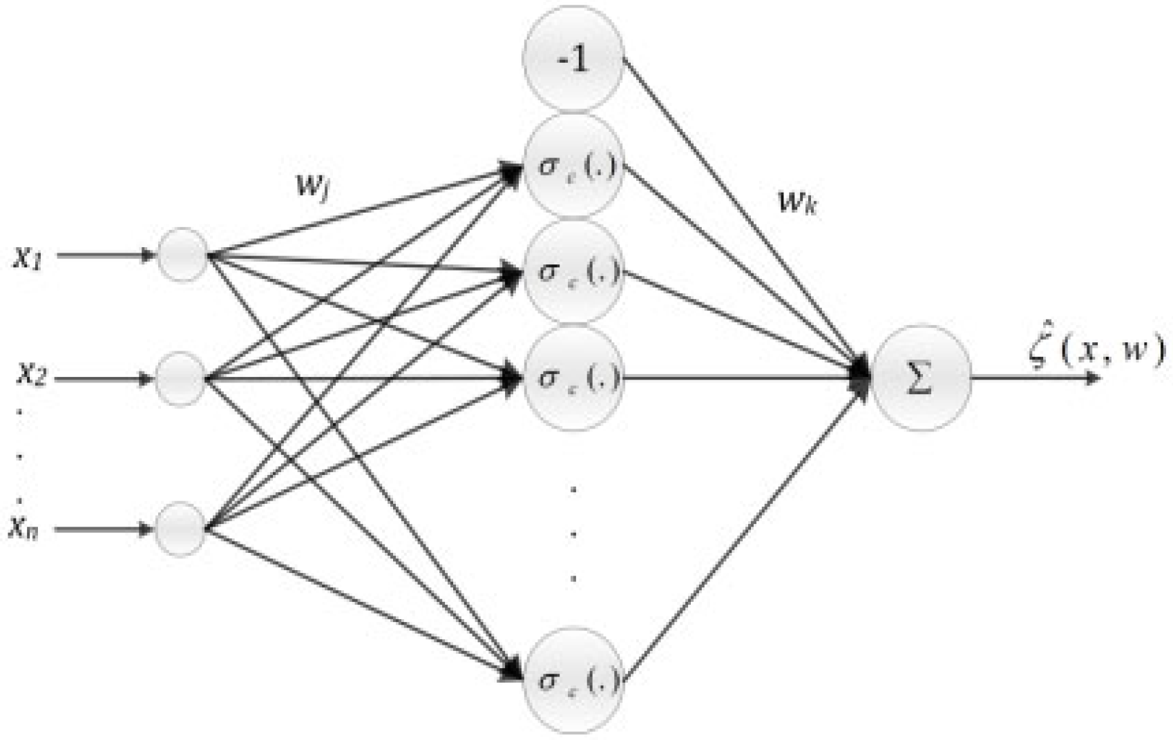
The neural network considered is a multi-layer perceptron (MLP), a type of predictive network.
Figure 1 illustrates the proposed neural network architecture, with the output variable calculated using the following equation:
In this study, a neural network—specifically a multi-layer perceptron (MLP)—is employed as an intelligent estimation and compensation mechanism to address input delays and modeling uncertainties within the wind energy system. The main objective is not to directly control the system but to enhance the accuracy of the control strategy by minimizing the mismatch between the nominal system output and the actual system behavior.
The neural network estimates unknown nonlinearities or uncertainties that are not captured by the nominal Takagi–Sugeno fuzzy model. These unknown components may stem from unmodeled dynamics, time-varying disturbances, or approximation errors. By learning these deviations in real-time, the neural network produces an adaptive corrective signal, which is then integrated back into the control input to compensate for delays and improve the tracking accuracy.
Equation (12) reflects the error between the nominal and the actual system outputs; the neural network works to minimize this error using a gradient descent-based online learning algorithm. The learning updates are computed iteratively to ensure the neural network adapts to changing system conditions.
The structure of the MLP is shown in
Figure 2, where
The input layer receives measured system variables.
The hidden layer processes the input using a tanh activation function, offering nonlinearity.
The output layer generates the estimated compensation signal.
The weights between the layers are continuously updated to optimize performance during real-time operation. This adaptive learning ensures that the neural network maintains an accurate model of the delay-induced uncertainty, even under varying operating conditions or in the presence of non-Gaussian disturbances.
By embedding this learned compensation term into the control framework, the overall system gains improved robustness, delay tolerance, and dynamic performance, without requiring an exact analytical model of the uncertainties or delays. The neural network thus plays a supporting, but crucial, role in ensuring the robustness and adaptability of the overall control scheme [
21].
Figure 2.
The neural network’s architecture [
22].
Figure 2.
The neural network’s architecture [
22].
Where something is the activation function, considered as a hyperbolic tangent function (tanh), N and n are, respectively, the number of hidden layer nodes and the number of network inputs. In addition, something and something are, respectively, the weights between the hidden layer and the output layer and the weights between the hidden layer and that of the input network.
The network weights are adjusted during the online implementation. The method used is based on the gradient descent method (GD). The essence of the GD method consists of iteratively adjusting the weights in the direction opposite to the gradient of E, so as to reduce the discrepancy according to the following:
The Delayed PDC Control
The most widely used control strategy for stabilizing nonlinear systems represented by T–S models is the Parallel Distributed Compensation (PDC) control approach [
23]. The control law employed in this method is similar to that of a standard PDC controller [
24], with the key difference being that it depends on the delayed state of the system. It is expressed as follows:
4. Robust Control with a Delayed Input
In this section, we address the problem of control with a delayed input. First, let us consider the system (2). The system, along with its control law, can be rewritten in the following form:
Theorem 1. For the two given scalars, γ > 0 and τ > 0, the system is asymptotically stable if there exist positive, definite, symmetric matrices, X > 0, Q > 0, S > 0, R > 0, and appropriately dimensioned matrices, , , , such that the following LMI condition is satisfied.
5. Energy Management Algorithm
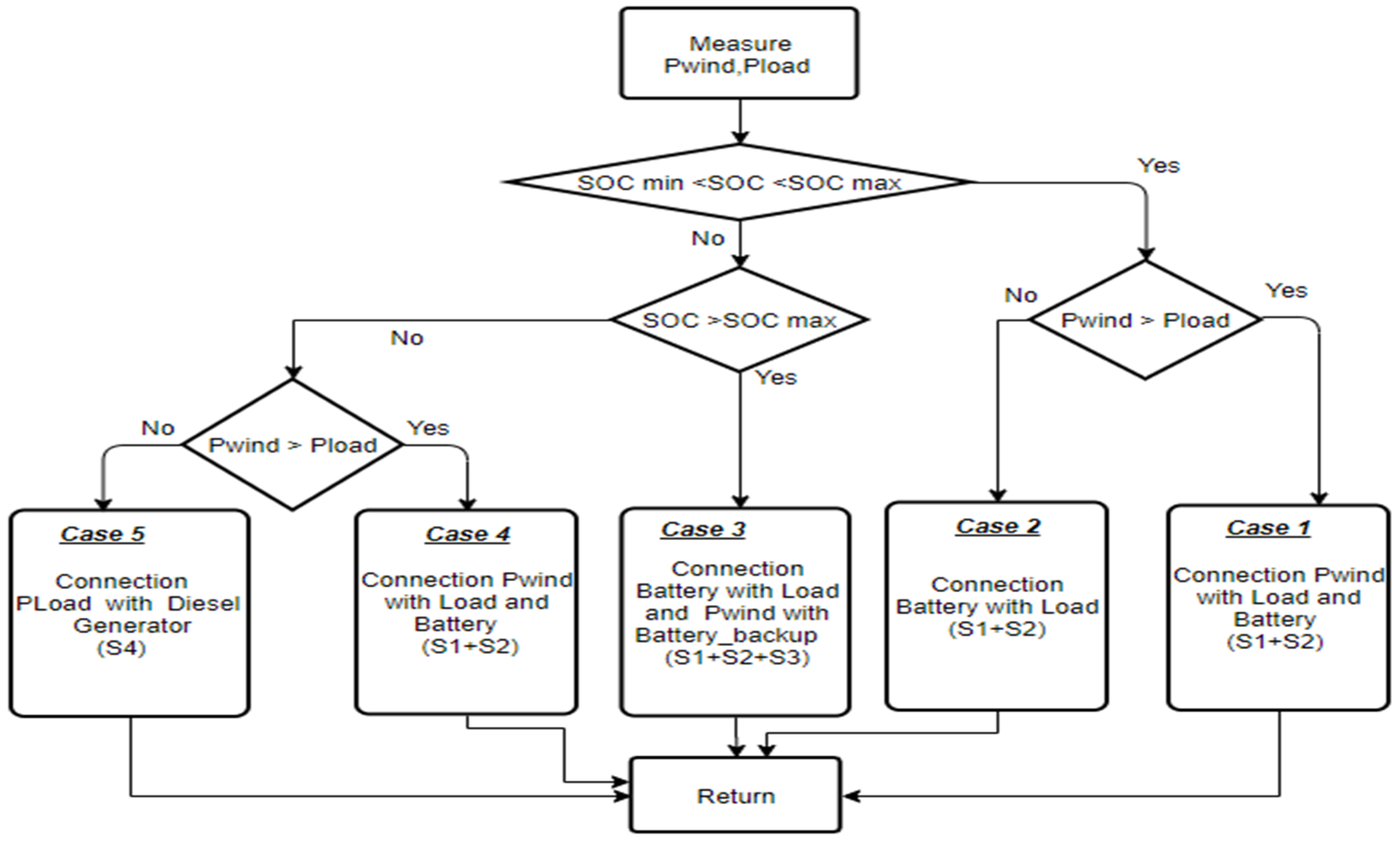
The algorithm presented in
Figure 3 outlines the energy management system we implemented using the Stateflow tool. This system is designed to handle various operational scenarios that may arise. The wind energy management strategy proposed here effectively manages both the wind power input and energy storage, ensuring the battery is safeguarded against excessive discharge and overcharging.
The control logic relies on three key input parameters:
Pwind: The available wind power.
Pload: The power demand from the load.
SOC (state of charge): The battery charge level, where the SOC is constrained between a minimum of 20% (to prevent deep discharging) and a maximum of 80% (to avoid overcharging).
The system accounts for five distinct operating scenarios:
Case 1:
When the battery’s state of charge (SOC) is within the safe range (20–80%), and the wind power output exceeds the load demand, the wind energy is sufficient to meet the load requirements and simultaneously recharge the battery.
Case 2:
If the SOC remains between 20% and 80%, but the wind power is lower than the load demand, the available wind energy is inadequate. In this situation, the battery compensates for the energy shortfall to ensure the load is fully supplied.
Case 3:
To prevent overcharging, once the SOC reaches the upper threshold of 80%, the system redirects the wind power to a backup battery. Meanwhile, the load remains connected to the primary battery.
Case 4:
When the battery is deeply discharged (SOC falls below 20%), and the wind power exceeds the load demand, the wind source supplies sufficient energy to power the load and begin recharging the battery.
Case 5:
If the SOC drops below 20%, and the wind source cannot provide enough power for the load, the available wind energy becomes insufficient. In this scenario, both the load and the battery are powered by a diesel generator.
5.1. Model of Battery
A dynamic battery model was implemented in MATLAB/Simulink. This generic model, detailed in [
24], is based on a lead-acid battery and described by the equations provided in [
25]. The model parameters were derived from the battery’s discharge characteristics, with the same values assumed for the charging process.
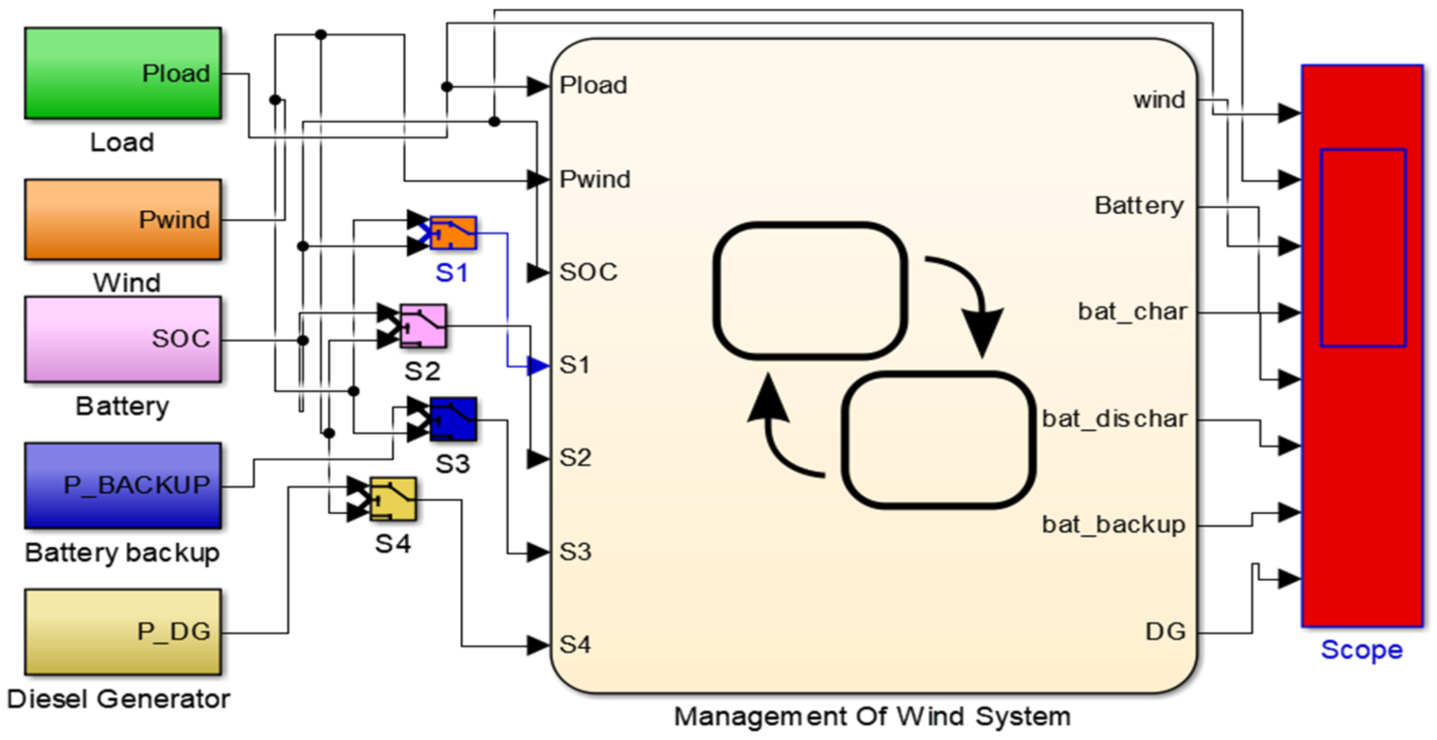
5.2. Diesel Generator Model
Figure 4 illustrates the energy management architecture of the wind-based power system. This setup integrates several components: the wind energy source, battery storage, electrical loads, a backup battery, and a diesel generator. The system also includes four switches (S1, S2, S3, and S4), which regulate the connections between the energy sources and the various subsystems, such as the battery and the load. All the components are coordinated through an energy management system. The core objective of this system is to implement a control algorithm using the Stateflow tool (Matlab/Simulink, MATLAB R2010a), enabling the efficient handling of operational constraints and dynamic decision-making within the hybrid energy setup.
The model comprises the following:
Stateflow variables:
Pload: The load power requested.
Pwind: The power supplied by the wind.
SOC: The state of charge of a battery.
Wind: The On/Off relay of the wind.
Battery: The On/Off relay of the battery.
bat_char: The On/Off relay of the charge.
bat_dischar: The On/Off relay of the discharge.
bat_backup: The On/Off relay of the battery backup.
DG: The On/Off relay of the diesel generator.
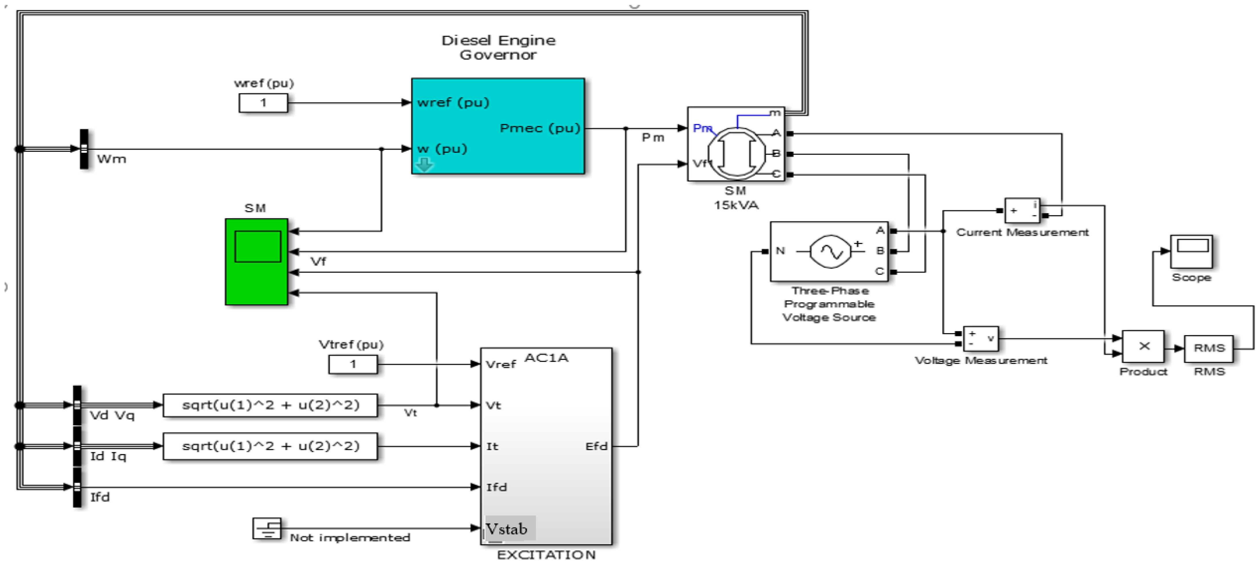
In standalone renewable energy systems, such as wind-based installations, incorporating energy storage or integrating one or more diesel generators is often essential to ensure reliability.
A typical diesel generator system consists of two primary components: a diesel engine and a synchronous generator. The diesel engine supplies the mechanical power needed to drive the generator while maintaining a constant rotational speed (ω) to ensure a stable output frequency. Electrical power is produced by the synchronous generator, and the output voltage is regulated by an excitation system to remain within its nominal range.
The dynamic behavior of the diesel engine is modeled using control system transfer functions, which also include the actuator’s response characteristics, as described in [
26].
where
represents the transfer function of the governor’s control system, while
is the transfer function for the actuator. T1, T2, and T3 are the time constants of the regulator. T4, T5, and T6 are the time constants of the actuator, and K is the regulator gain;
Figure 5 illustrates the diesel generator system, as implemented in MATLAB/Simulink. This model includes the diesel engine, the governor system, the synchronous generator, and its excitation system, which together determine the dynamic response and power output of the generator.
6. Example and Simulation
To illustrate the proposed fuzzy robust tracking control condition, a control problem of a wind generator is considered.
By defining the state vector as
and the control signal as
the reference state vector to track can be defined as
and the fuzzy model of the WECS can be described as
where
where
denotes the torsion angle,
is the angular velocity of the rotor,
is the angular velocity of the generator,
is the stiffness of the transmission,
is the damping of the transmission, and
and
are the inertia of the rotor and the generator, respectively.
is the aerodynamic torque. and are the actual and the desired pitch angles, respectively.
T-S Fuzzy Modeling
The wind generator system is then described by the following four if–then rules:
If β is
, and
is
, then
If β is
, and
is
, then
If β is
, and
is
, then
If β is
, and
is
, then
In order to obtain the best performance from this nonlinear system (16), the following T-S fuzzy model is given:
The parameter uncertainties, , represent the impossibility of an exact mathematical model of a dynamic system due to the system complexity. If the wind generator is a complex system, then the presence of uncertainties is possible.
The control objective we aimed to attain was the best tracking of the rated power while regulating the rotor speed.
We considered a network-based T-S fuzzy system for output tracking control, and we showed the effectiveness of the proposed method by performing output tracking control simulations for the T-S fuzzy system.
The simulation results of the wind system control method and energy system management are presented in this section.
In solving the LMI problem stated in Theorem 1, we obtained the results in terms of gains; it is clear that the proposed approach gives better results.
The simulation results of the LMI problem show that the attenuation level is 0.3442, so we can deduce that the designed T-S fuzzy controller ensures a good tracking performance and can guarantee stability.
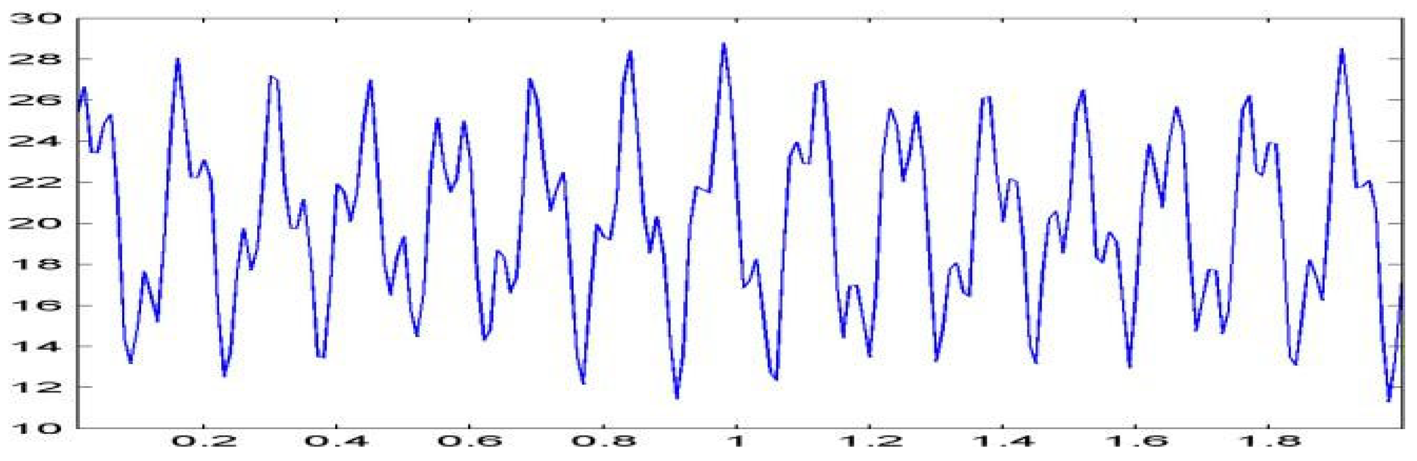
For the simulation, we considered the wind speed input profile (11 m/s < V < 29 m/s), as given in
Figure 6.
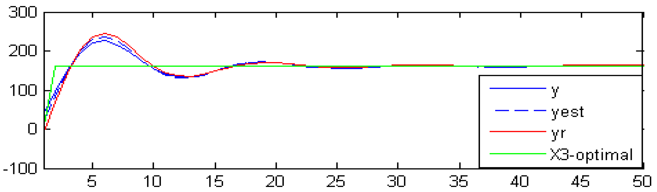
The
Figure 7 above illustrates the rotor speed tracking performance.
The
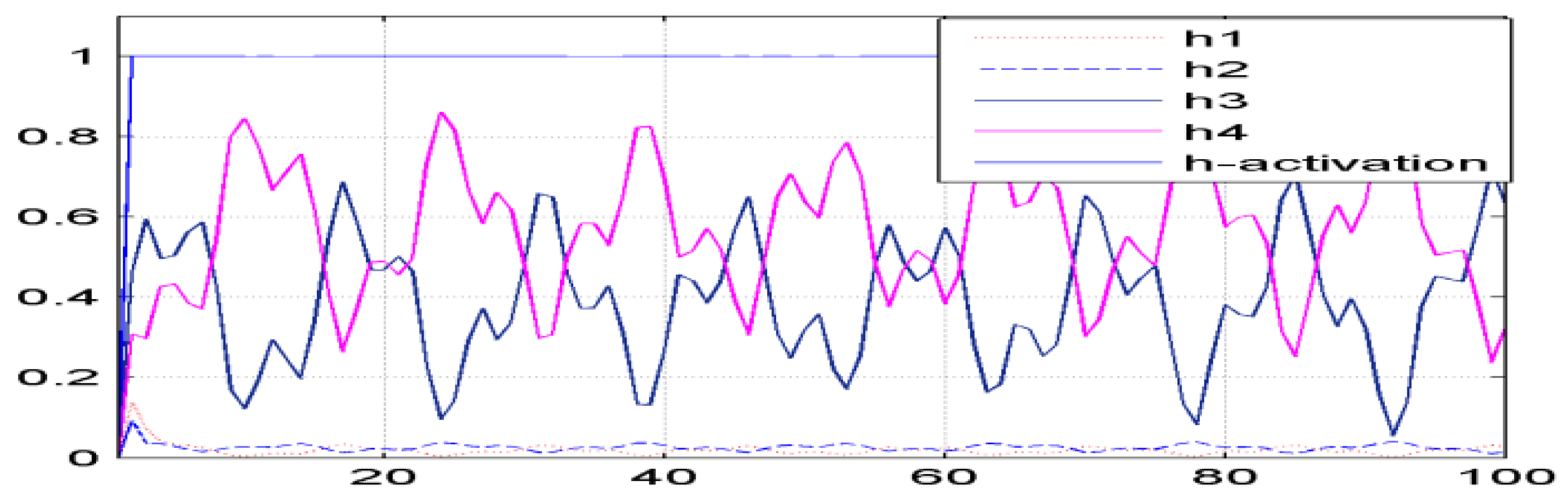
Figure 7 above illustrates the rotor speed tracking performance. It is evident that the actual speed closely follows the reference trajectory, even under varying wind speed conditions. This indicates that the implemented Takagi–Sugeno (T-S) fuzzy controller provides effective and accurate tracking. The next
Figure 8 displays the corresponding membership functions used in the controller design.
7. Conclusions
In this study, a sufficient condition for the robust stabilization of uncertain, nonlinear wind turbine systems subject to external disturbances and input delays was proposed. Building upon previous research, the proposed framework integrates advanced control strategies using Takagi–Sugeno (T-S) fuzzy modeling to effectively handle system uncertainties and delay effects. A robust fuzzy observer-based tracking controller was designed to minimize tracking errors and mitigate the impact of disturbances. The control design was formulated using a quasi-Linear Matrix Inequality (LMI) approach, enabling its practical implementation and scalability. Additionally, a delayed-state feedback control law based on Parallel Distributed Compensation (PDC) was developed, supported by an observer, to ensure the system’s stability. The stability conditions were rigorously established using a quadratic Lyapunov function and expressed as LMIs, allowing for computational efficiency in the controller’s synthesis. The simulation results demonstrate that the proposed method successfully stabilizes the wind energy system, enhancing its robustness, delay tolerance, and control accuracy in the presence of external disturbances. Overall, this study contributes to a unified and effective control strategy for the reliable operation of wind turbine systems under real-world uncertainties.


