Article

Optimization of Chip Morphology in Deep Hole Trepanning of Titanium Alloy

1
State Key Laboratory of Metal Forming Technology and Heavy Equipment, China National Heavy Machinery Research Institute Co., Ltd., Xi’an 710032, China
2
Mechanical Engineering College, Xi’an Shiyou University, Xi’an 710065, China
3
Shaanxi Shenkong Zhiyue Technology Co., Ltd., Xi’an 712000, China
*
Author to whom correspondence should be addressed.
Processes 2025, 13(7), 2082; https://doi.org/10.3390/pr13072082
Submission received: 30 April 2025 / Revised: 18 June 2025 / Accepted: 27 June 2025 / Published: 1 July 2025
(This article belongs to the Section Manufacturing Processes and Systems)

Abstract

Deep hole trepanning of large-diameter titanium alloy rods presents several challenges, including chip breaking, chip clogging, tool wear, and chipping. To address these issues, an optimized multi-tooth trepanning design was developed. An L9 orthogonal experimental array was employed to assess the influence of cutting speed, feed rate, and cutting fluid pressure on the chip volume ratio and to determine optimal process parameters. Results indicate that the impact of process parameters on the chip volume ratio of the first and third cutting teeth follows the order of cutting speed, feed rate, and cutting fluid pressure. Optimal chip morphology for internal chip removal is achieved with a cutting speed of 63.3 m·min−1, a feed rate of 0.18 mm·r−1, and a cutting fluid pressure of 4 MPa. Conversely, improper parameter matching can result in numerous long spiral chips, causing adhesive wear, diffusion wear of the multi-tooth drill, and severe chipping of the cutting edge.

1. Introduction

Titanium alloy tubes are widely used in various fields such as aviation, aerospace, petroleum, and chemical industries due to their low density, good corrosion resistance, and thermal stability [1]. The primary methods for producing large-diameter titanium alloy tubes include rotary piercing, deep hole drilling, and deep hole trepanning, as illustrated in Figure 1. Rotary piercing is a commonly used process in the production of titanium alloy tubes; however, it involves complex processing equipment and a long processing cycle, primarily for low-strength titanium alloys [2]. Deep hole drilling directly drills bars to obtain tubes, resulting in low material utilization [3]. Deep hole trepanning uses annular cutting to process holes in solid materials, leaving a core after processing [4]. For large-diameter titanium alloy tubes, deep hole trepanning can minimize costs and save raw materials. However, the high strength, strong chemical activity, and poor thermal conductivity of titanium alloys make chip breaking difficult during deep hole trepanning, leading to chip clogging, difficult chip removal, and easy tool wear and breakage. These issues force interruptions in the drilling process and reduce drilling efficiency [5]. These problems significantly limit the application of large-diameter titanium alloy tubes and are urgent challenges in the industrial field.
The central challenge in deep hole trepanning lies in concurrently addressing multiple interdependent factors—chip evacuation, cooling efficiency, vibration mitigation, tool wear management, and dimensional accuracy—within spatially constrained boreholes subjected to extreme thermomechanical conditions (elevated temperatures, pressures, and friction). Due to the enclosed machining environment and limited access, the direct in-process monitoring of critical state variables (e.g., cutting forces, temperature distributions) remains impractical [6]. As a result, chip morphology serves as a crucial, albeit dynamically evolving, proxy for evaluating process stability. However, quantitatively characterizing chip features is inherently difficult, as their attributes shift continuously in response to tool wear progression, thermal gradients, and material flow instabilities during extended drilling operations [7]. Despite the underlying complexity—driven by coupled interactions among material behavior, transient thermomechanical phenomena, and fluid dynamics—the targeted optimization of key controllable parameters remains a practical and effective strategy for guiding chip morphology toward functionally favorable outcomes.
Chip morphology is a key factor affecting the smoothness of chip removal, influenced by machining conditions such as tool, workpiece material properties, and process parameters [8]. Different machining conditions produce varying chip morphologies. During the machining process, the tool parameters and workpiece material are predetermined, leaving only the process parameters adjustable on-site. These parameters include cutting speed, feed rate, depth of cut, and cutting fluid parameters [9]. Sun analyzed chip morphology in the end milling of titanium alloy, finding that chip length increased with higher cutting speeds and feed rates, while chip width decreased [10]. Polli et al. investigated the deep drilling of SAE 4144 M, finding suitable chip morphology under lower cutting speeds and higher feed rates [11]. Słodki et al. discovered that chip breakage is more effective with increased feed rates in stainless steel turning [12]. Feng observed that smaller feed rates produce many spiral curled chips in the deep hole drilling of TA10, leading to chip clogging, tool wear, and chipping [13]. Moghaddas optimized chip morphology in ultrasonic-assisted drilling of Aluminum 6061 using response surface methodology, finding smaller chip morphology sizes under lower cutting speeds and feed rates [14]. Tian studied chip morphology in the drilling of 304 stainless steel using orthogonal experiments, showing that chips were longer and had a slightly increased curl radius with higher rotational speeds. Lower feed rates and appropriate rotational speeds benefit chip breaking [15]. Proper cutting fluid parameters also improve chip evacuation. Zębala found that chips were more prone to break with increased cutting fluid pressure in the turning process of Ti6Al4V [16]. Higher cutting fluid pressure also aids in chip removal [17]. Therefore, process parameters and cutting fluid parameters significantly affect chip morphology. Surface roughness, material removal rate, and chip volume ratio are key machining performance indicators used to optimize process parameters [18,19,20]. Among these, the chip volume ratio serves as a critical metric for evaluating chip morphology. It quantifies the extent to which the transport volume required by a given chip form exceeds the intrinsic material volume of the chip itself. This parameter directly correlates chip morphology with evacuation efficiency, particularly in the spatially constrained environment of trepanning tools.
Despite the critical role of chip morphology in machining performance, studies focusing on chip evacuation in deep hole trepanning of titanium alloys remain limited. To enhance chip removal efficiency, the multi-tooth deep hole trepanning of Ti6Al4V rods was investigated. An L9 orthogonal experimental design was employed to optimize process parameters. By analyzing the chip volume ratio of the first and third cutting teeth, optimal parameter combinations were identified. Additionally, certain experimental conditions produced excessive chip accumulation, hindering effective evacuation; accordingly, tool wear under those conditions was further examined.

2. Experimental Methods

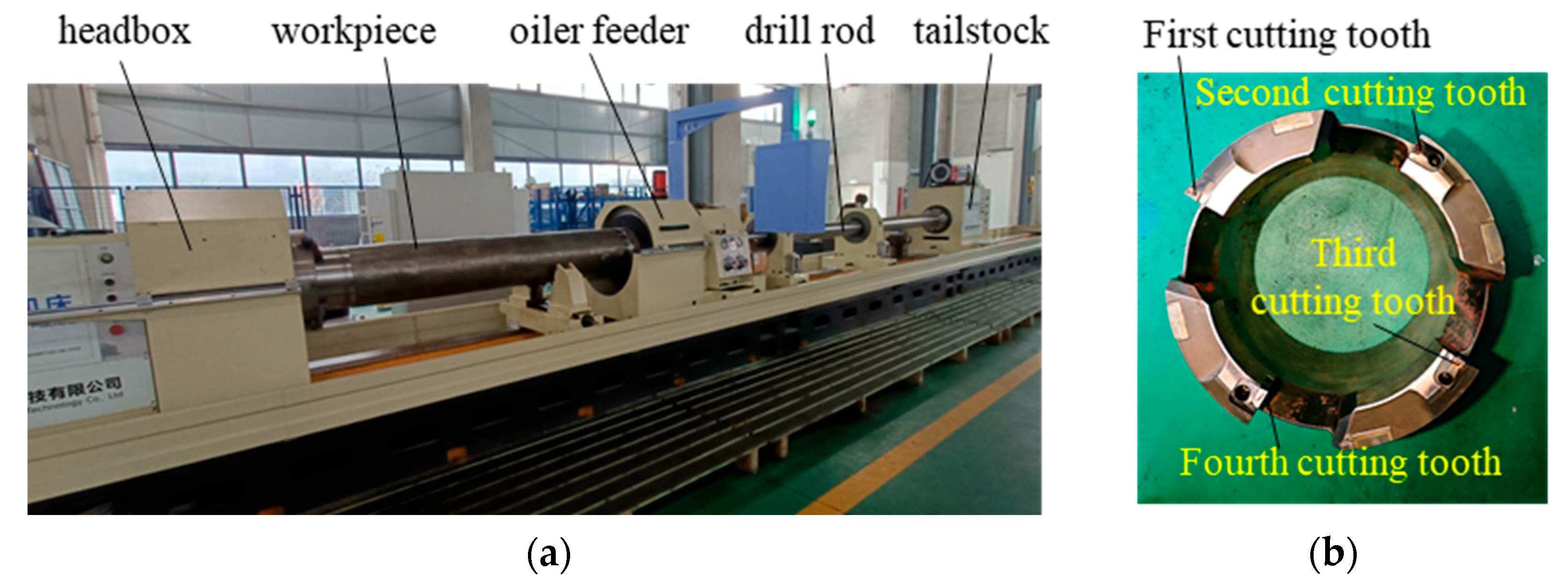
The deep hole trepanning experiment was conducted on a TK deep hole machine, as shown in Figure 2. The machine includes a headbox, oil feeder, tailstock, and drill rod. The headbox is connected to a three-jaw chuck that drives the workpiece to rotate, while the tailstock drives the drill rod and multi-tooth drill to feed. The workpiece is made of Ti6Al4V titanium alloy rod, with a diameter of 360 mm and a length of 2300 mm. The multi-tooth drill uses a four-tooth drill, with an outer diameter of 170 mm and an inner diameter of 125 mm. It includes four cutting teeth: the first cutting tooth, the second cutting tooth, the third cutting tooth, and the fourth cutting tooth are shown in Figure 2b. The main parameters of the four cutting teeth are shown in Table 1.
To investigate the influence of process parameters on chip morphology, an L9(33) orthogonal experimental design was implemented. Cutting speed, feed rate, and cutting fluid pressure were selected as independent variables, each evaluated at three levels, resulting in a total of nine experimental runs. The parameter ranges were established based on machining experience and reference literature. For instance, Rahim examined TC4 titanium alloy drilling at cutting speeds between 50 and 70 m·min−1 [21]; Li et al. recommended speeds of 40–120 m·min−1 for drilling low-carbon alloy steel [22], and studied BTA drilling of low alloy steel at 61–80 m·min−1 with feed rates of 0.12–0.18 mm·rev−1 [23]. Feng et al. explored trepanning of TC10 alloy with feed rates from 0.05 to 0.20 mm·rev−1 [13], while Liu et al. analyzed TC4 turning within the same feed range [24]. Polli et al. investigated chip morphology in SAE 4144M steel, demonstrating that lower cutting speeds combined with higher feed rates facilitate chip evacuation [11].
Guided by these findings, the cutting speed was set between 63.3 and 81.4 m·min−1, the feed rate from 0.18 to 0.20 mm·rev−1, and the cutting fluid pressure from 2.5 to 5.5 MPa, as detailed in Table 2. The cutting fluid used was a blend of 20# and 10# industrial lubricating oils. The trepanning tool features four radially arranged teeth in a staggered configuration. Owing to the tool’s central symmetry—where the first and second teeth are symmetric to the third and fourth—the first and fourth teeth exhibit similar widths and chip characteristics, as do the second and third. Accordingly, the chip volume ratios of the first and third cutting teeth were selected as representative indicators for analyzing chip morphology. These ratios were calculated based on Equation (1) [20].
R = V q V j
where Vq represents the volume of the main metal chips removed. Vj represents the actual volume of the same amount of material removed. The Vq is derived by calculating the relevant parameters of the chips, such as length and radius of curvature, which are measured using microscopy. The Vj is calculated from the mass and density of the same amount of material removed.
Inappropriate chip morphology can lead to tool wear or chipping during the deep hole trepanning of titanium alloy, causing interruptions in the process. Therefore, the most severely worn tools from the orthogonal experiment were selected for microscopic analysis. The microstructure of the first and third cutting teeth surfaces was analyzed using a JSM-7610FPlus scanning electron microscope, and energy spectrum analysis was conducted to examine the wear conditions. The JSM-7610FPlus scanning electron microscope was manufactured by JEOL Ltd. in Akishima, Japan.

3. Results and Analysis

3.1. Analysis of the Orthogonal Experiment

Nine deep hole trepanning experiments were conducted using an orthogonal design. The chip volume ratios for the first and third cutting teeth were measured and are presented in Table 3. To evaluate the influence of process parameters on chip removal efficiency, the values of Kᵢ and R were analyzed. Here, Kᵢ represents the average chip volume ratio at the ith level of a given factor, while R denotes the range of variation across levels for each factor. A larger R value indicates a stronger influence of that factor on the chip volume ratio.
According to the R values presented in Table 4, the influence of process parameters on the chip volume ratio of the first cutting tooth, in descending order, is cutting speed, feed rate, and cutting fluid pressure. This trend aligns with the findings reported in [25], confirming that cutting speed exerts a greater impact on chip formation than feed rate. Based on the Kᵢ values in Table 4, an initial selection of the optimal factor levels can be made. A lower chip volume ratio is advantageous for efficient chip evacuation. Accordingly, the analysis of the Ki values for cutting speed, feed rate, and cutting fluid pressure suggests that the optimal parameter combination is A1B1C2—that is, cutting speed (A) at level 1, feed rate (B) at level 1, and cutting fluid pressure (C) at level 2.
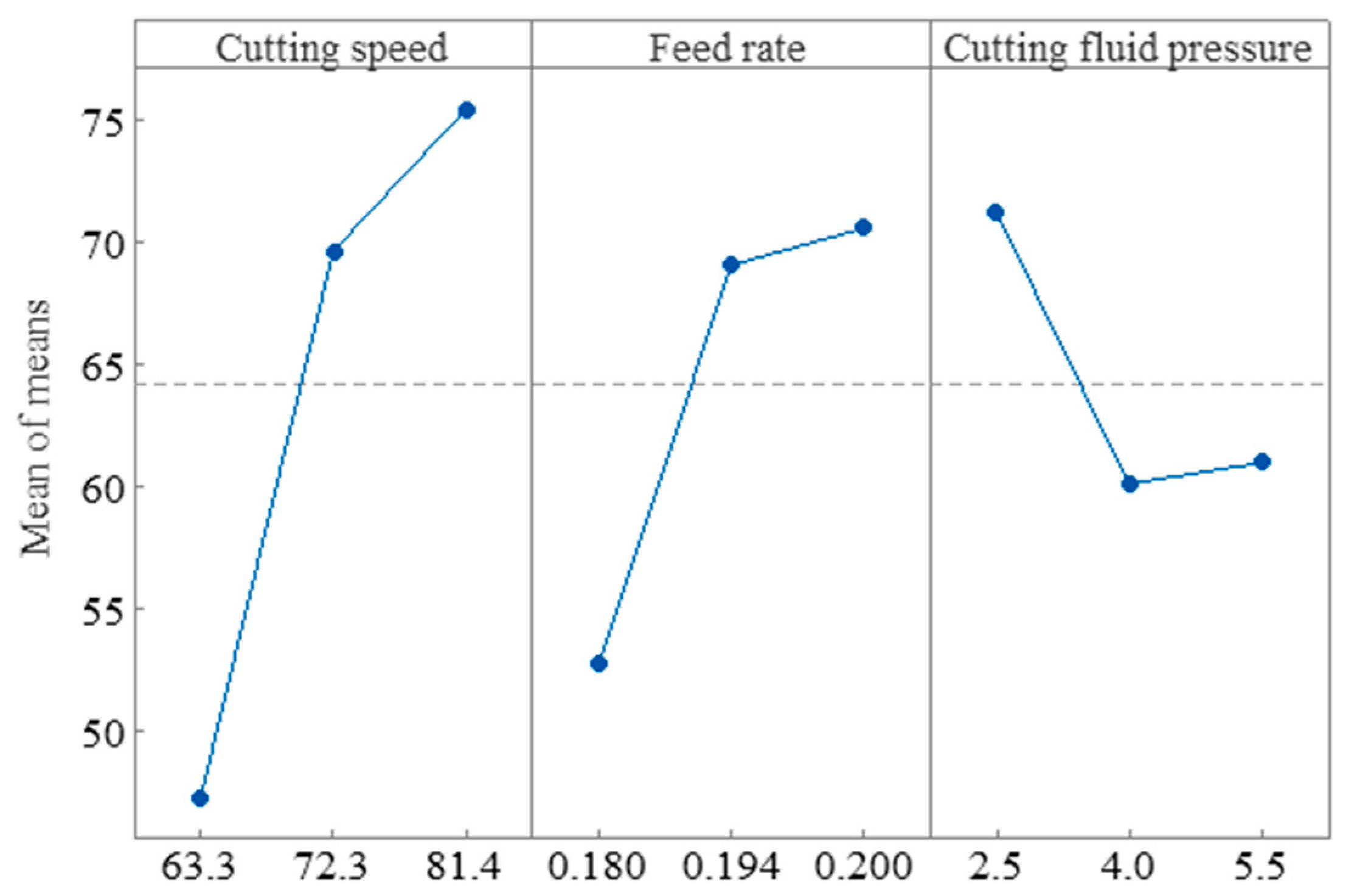
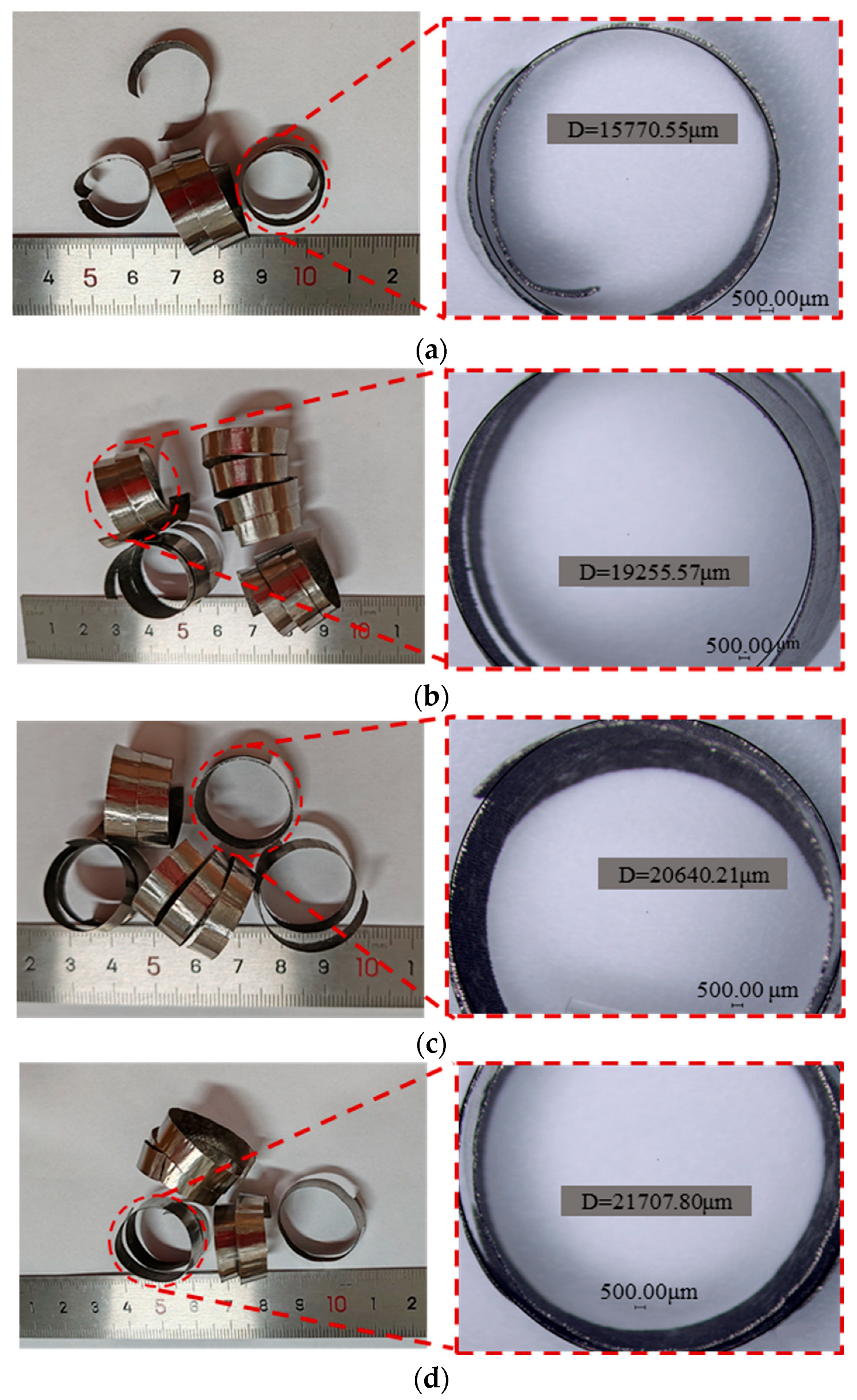
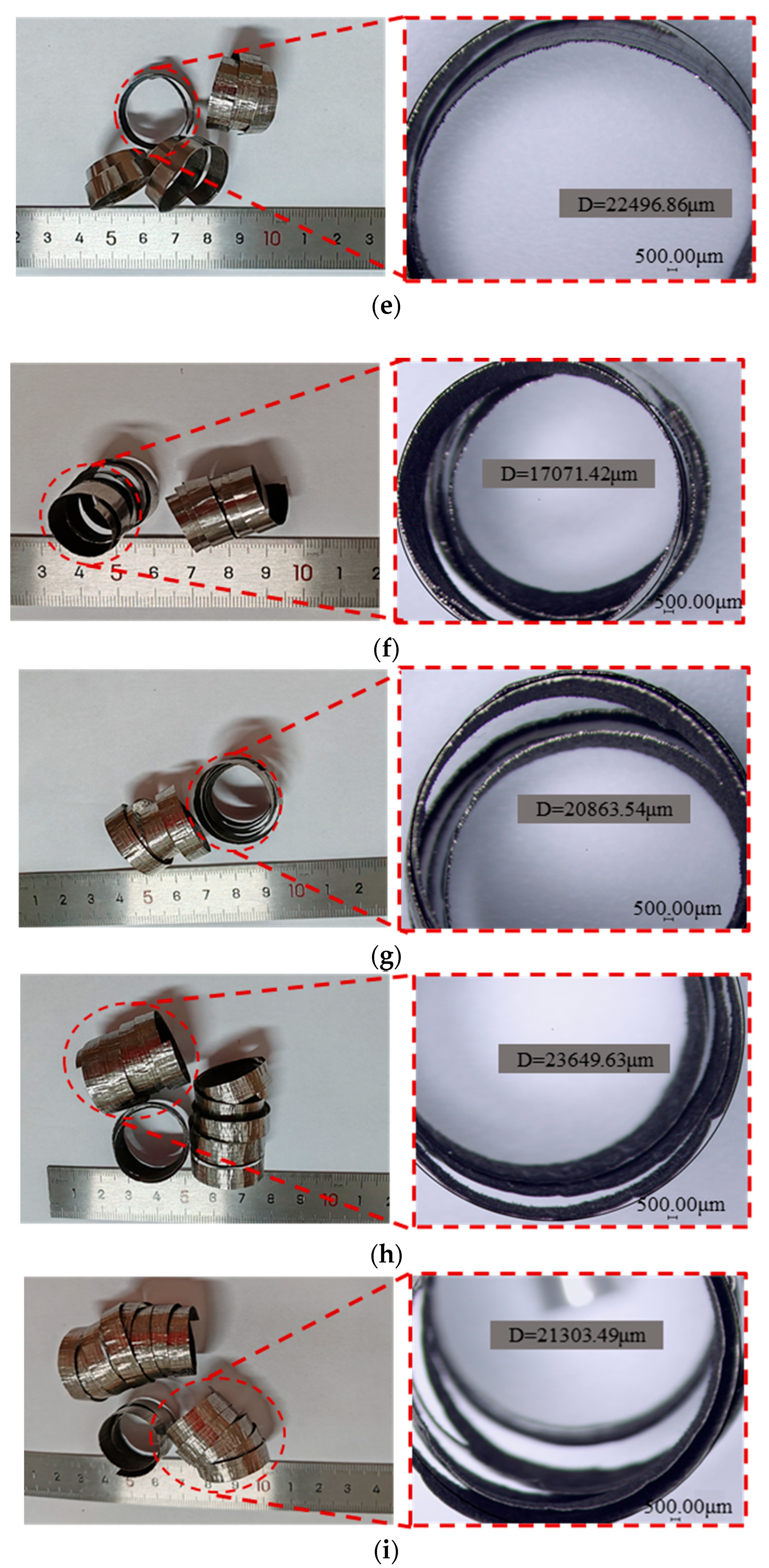
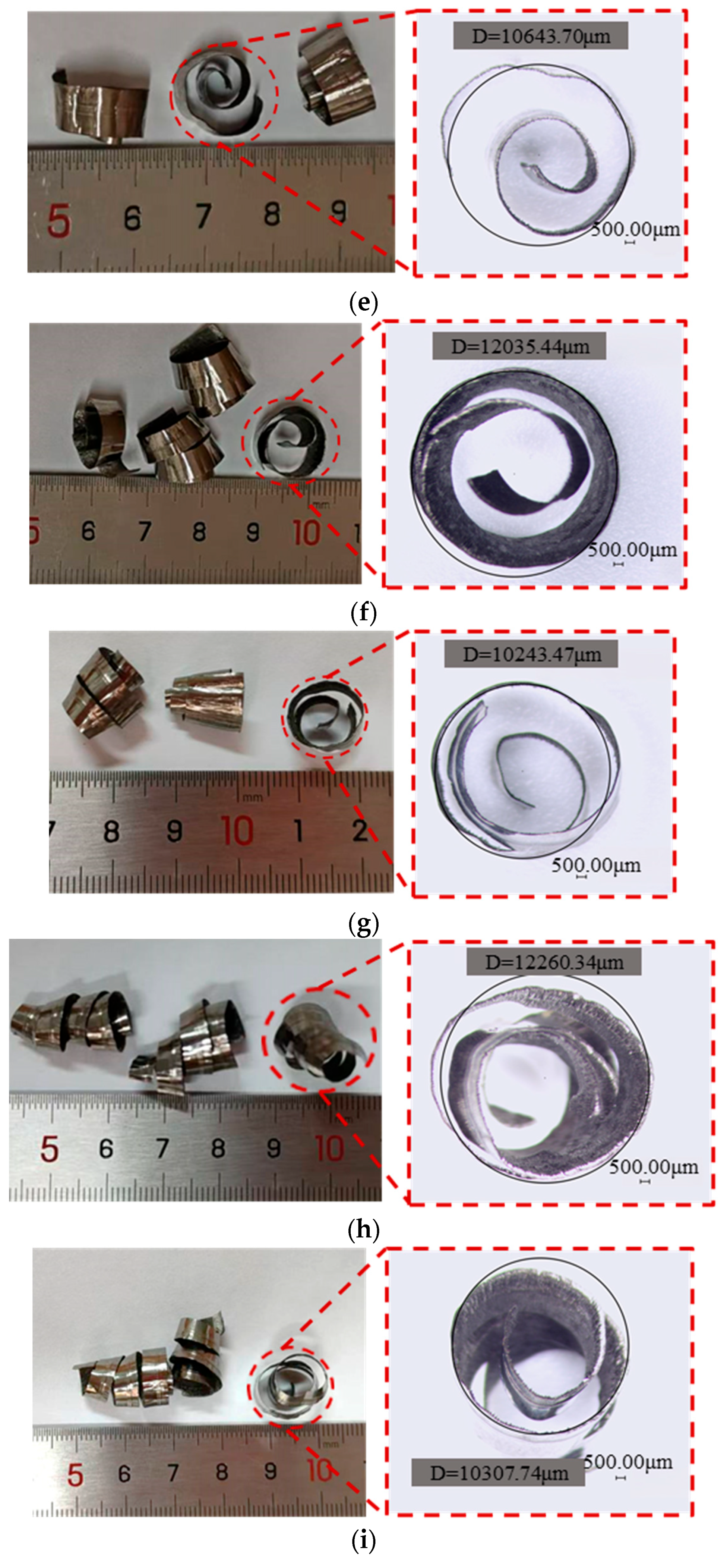
Figure 3 illustrates the relationship between the chip volume ratio of the first cutting tooth and the process parameters across three levels. Each data point represents the mean chip volume ratio corresponding to a specific parameter level. The results show a gradual increase in chip volume ratio with increasing cutting speed. The first cutting tooth is located on the outermost side of the four-tooth drill, with the largest cutting radius and the highest cutting speed among the four teeth, primarily producing long spiral chips. Higher cutting speed results in more spirals in the long chips produced by the first cutting tooth, changing from short spirals to long spirals, leading to an increase in chip volume and thus an increase in chip volume ratio, as shown in Figure 4. As the feed rate increases, the chip volume ratio of the first cutting tooth also increases. With an increase in feed rate, the chip thickness increases; however, since the feed rate increase is small, the chip thickness does not reach the level of hardening and breaking within this range. Instead, the number of spirals in the chips gradually increases, increasing the chip volume ratio. As the cutting fluid pressure increases, the chip volume ratio of the first cutting tooth first decreases and then slowly increases. As the cutting fluid pressure increases, it helps reduce adhesion between the chips and the tool or workpiece, promoting chip separation and discharge, thereby reducing the chip volume ratio. When the cutting fluid pressure increases to a certain value, its impact on the chip volume ratio becomes minimal. This is primarily due to the fact that chip breakage and chip removal are complex problems influenced by the viscosity of the cutting fluid, the pressure, and the type of chip morphology. Cutting fluid pressure can only partially affect chip removal but is not a decisive factor.
Furthermore, the ANOVA results in Table 5 statistically quantify the contributions of cutting speed, feed rate, and cutting fluid pressure to the chip volume ratio of the first cutting tooth. The F-value and p-value serve as critical indicators for assessing statistical significance, where a higher F-value and lower p-value denote a more substantial effect. As shown in Table 5, cutting speed exhibits the most significant influence, contributing 59.42% to the variation in chip volume ratio, followed by feed rate (26.20%) and cutting fluid pressure (10.33%).
Similarly, as shown in Table 4 and Figure 5, the process parameters influencing the chip volume ratio of the third cutting tooth follow the same descending order of significance: cutting speed, feed rate, and cutting fluid pressure. Based on the analysis of the Kᵢ and R values, the optimal parameter combination is identified as A1B1C2. Thus, the recommended settings for minimizing the chip volume ratio of the third cutting tooth are: cutting speed (A) at level 1, feed rate (B) at level 1, and cutting fluid pressure (C) at level 2.
The chip morphology produced by the third cutter tooth is mainly spiral cone chips, as shown in Figure 6. As the cutting speed increases, the taper of the spiral cone chips produced by the third cutter tooth becomes larger, gradually developing from short spiral chips to long spiral chips, accompanied by irregular chip spirals. The increase in chip length leads to an increase in chip volume, thereby increasing the chip volume ratio. As the feed rate increases, the chip thickness increases; however, within this range, the chip thickness does not reach the level of hardening and breaking, instead causing the number of chip spirals to gradually increase, thus increasing the chip volume ratio. Usca et al. also investigated this phenomenon, noting that an increased feed rate leads to greater chip volume, thereby elevating the chip volume ratio [26]. As the cutting fluid pressure increases, the chip volume ratio of the third cutter tooth initially decreases and then slowly increases. The third cutter tooth is located slightly inside the trepanning drill, and the influence of cutting fluid pressure on the chip accommodation coefficient is relatively small.
The ANOVA results presented in Table 6 statistically quantify the contributions of cutting speed, feed rate, and cutting fluid pressure to the chip volume ratio of the third cutting tooth. The analysis of the F-values and p-values indicates that cutting speed and feed rate exert the greatest influence, while cutting fluid pressure has the least impact. Specifically, the contributions of cutting speed, feed rate, and cutting fluid pressure are 71.24%, 19.18%, and 8.80%, respectively.
Considering both optimization indicators, the influence of process parameters on the chip volume ratio for the first and third cutting teeth, in descending order, is cutting speed, feed rate, and cutting fluid pressure. The optimal parameter combination for improving chip morphology in deep hole trepanning of Ti6Al4V is A1B1C2, corresponding to a cutting speed of 63.3 m·min−1, a feed rate of 0.18 mm·rev−1, and a cutting fluid pressure of 4 MPa.

3.2. Tool Wear

In actual machining, application of the process parameters from the orthogonal experiment 8 during deep hole trepanning resulted in the formation of numerous coarse, helical chips when penetrating the workpiece. The first cutting tooth generated spiral chips up to 140 mm in length. These elongated chips accumulated and twisted within the confined trepanning space, causing severe chip blockage. This obstruction impeded coolant penetration and chip evacuation, leading to elevated cutting zone temperatures and increased mechanical stress. The resulting high-temperature softening of the tool matrix promoted adhesive and diffusion wear, accelerated coating delamination, and, combined with cyclic stresses, induced fatigue micro-chipping. These interacting failure mechanisms significantly accelerated tool wear.
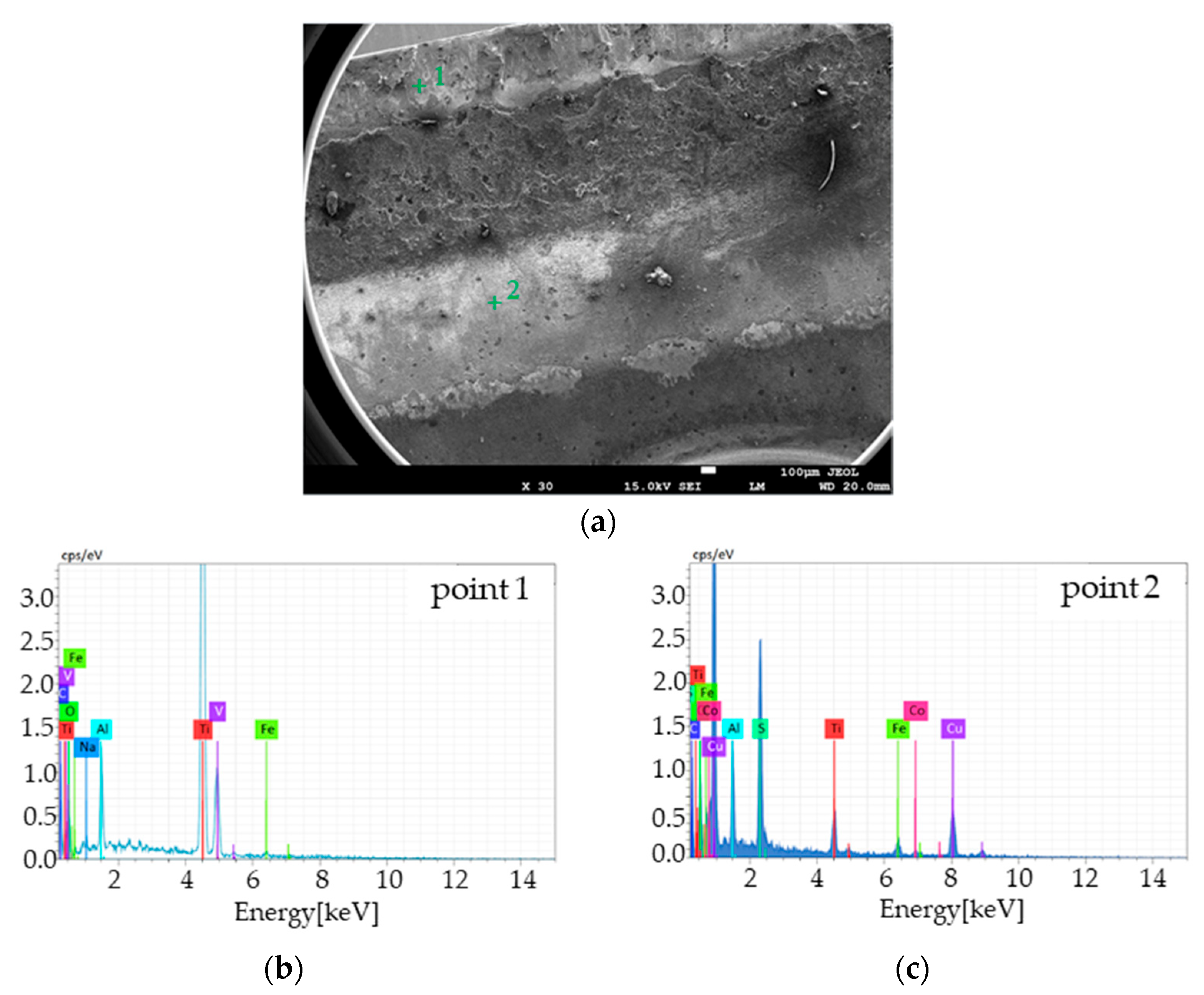
To investigate adhesive and diffusion wear mechanisms, energy-dispersive spectroscopy (EDS) was performed on the worn areas of the cutting tool. Characteristic wear signatures—including tip degradation and discoloration of the rake face—were observed. Spectral analysis was conducted at selected points on the first and third cutting teeth to assess material transfer and degradation.
Figure 7a presents the SEM image of the first cutting tooth’s rake face, revealing chipping and exposure of the carbide substrate. At Point 1, EDS analysis (Figure 7b) detected titanium (Ti), aluminum (Al), and vanadium (V) on the rake face, indicating material transfer from the workpiece. During deep hole trepanning, the outermost cutting tooth—primarily responsible for producing long spiral chips—is subjected to high pressure and temperature. These conditions promote chip adhesion to the rake face, forming built-up edges (BUEs). As machining progresses, chip accumulation intensifies BUE formation, which periodically fractures under external forces or vibration, causing adhesive wear. The repeated formation and detachment of BUEs remove tool material and contribute to surface rupture and edge chipping.
Similarly, EDS analysis at Point 2 confirmed Ti, Al, and V deposition, indicating diffusion wear. Sustained chip contact with the rake face at elevated temperatures facilitates elemental interdiffusion, altering tool composition and reducing mechanical strength through solid-solution weakening.
Figure 8 presents the wear analysis of the third cutting tooth. Similar to the first cutting tooth, the rake face exhibits predominant diffusion and adhesive wear; however, the overall wear severity is notably lower. As shown in Figure 8a, localized coating delamination is evident, but no chipping has occurred. This reduced wear is attributed to the third cutting tooth’s inner position on the four-tooth drill, where it generates spiral conical chips with smaller width and bending radius than those formed by the outermost tooth. These more compact chips are more easily discharged, thereby mitigating wear on the rake face.
To further investigate the wear mechanisms, energy-dispersive spectroscopy (EDS) was conducted at Points 1 and 2, as shown in Figure 8b,c. Elevated concentrations of titanium (Ti), aluminum (Al), and vanadium (V) were detected at both locations. The rake face exhibited the most severe degradation, with adhesive wear forming distinct pits and a clearly visible built-up edge. This material transfer under high thermal and mechanical loads confirms the presence of strong adhesive interactions and diffusion-induced wear.
In summary, wear analysis of the first and third cutting teeth confirms that both primarily undergo diffusion and adhesive wear. These wear mechanisms are consistent with the findings reported in references [27,28] and are attributed to the inherent properties of TC4 titanium alloys.

4. Conclusions

This study investigated the effects of key process parameters—cutting speed, feed rate, and cutting fluid pressure—on the chip volume ratio of the first and third cutting teeth during deep hole trepanning. An L9 orthogonal array was employed, and both range analysis and ANOVA were used to quantitatively evaluate the significance of each parameter. The results demonstrated that cutting speed had the greatest influence on chip volume ratio, followed by feed rate, while cutting fluid pressure had the least impact. Distinct chip morphologies were observed for each tooth: the first cutting tooth predominantly generated long spiral chips, whereas the third produced spiral cone chips. Optimal chip evacuation was achieved under the process parameters of 63.3 m·min−1 cutting speed, 0.18 mm·rev−1 feed rate, and 4 MPa cutting fluid pressure. Notably, during the drill exit phase of Experiment 8, chip morphology deviated from stable conditions, with an increase in long spiral chip formation. Wear analysis under these conditions indicated that adhesive and diffusion wear were the dominant failure mechanisms for both the first and third cutting teeth.

Author Contributions

Conceptualization, F.X. and X.H.; methodology, X.H.; validation, F.X., L.Q., and H.M.; formal analysis, F.X. and X.H.; investigation, L.Q.; resources, X.H.; data curation, H.M.; writing—original draft preparation, X.H.; writing—review and editing, X.H.; visualization, X.H.; supervision, X.H.; project administration, X.H.; funding acquisition, X.H. All authors have read and agreed to the published version of the manuscript.

Funding

This research was funded by the Natural Science Basic Research Program of Shaanxi (NO: 2023-JC-YB-387), State Key Laboratory of Metal Forming Technology and Heavy Equipment (NO:S2308100.W10), and Xixian New Area Science and Technology Plan Project (NO:XJZZ-2023-010).

Data Availability Statement

The original contributions presented in this study are included in the article. Further inquiries can be directed to the corresponding author.

Conflicts of Interest

Authors F.X./L.Q./H.M. were employed by the company China National Heavy Machinery Research Institute Co., Ltd. Authors X.H. were employed by the Xi’an Shiyou University and Shaanxi Shenkong Zhiyue Technology Co., Ltd. The remaining authors declare that the research was conducted in the absence of any commercial or financial relationships that could be construed as a potential conflict of interest.

References

  1. Zhao, Q.; Sun, Q.; Xin, S.; Chen, Y.; Wu, C.; Wang, H.; Xu, J.; Wan, M.; Zeng, W.; Zhao, Y. High-Strength Titanium Alloys for Aerospace Engineering Applications: A Review on Melting-Forging Process. Mater. Sci. Eng. A 2022, 845, 143260. [Google Scholar] [CrossRef]
  2. Topa, A.; Cerik, B.C.; Kim, D.K. A Useful Manufacturing Guide for Rotary Piercing Seamless Pipe by ALE Method. J. Mar. Sci. Eng. 2020, 8, 756. [Google Scholar] [CrossRef]
  3. Yuan, C.G.; Pramanik, A.; Basak, A.K.; Prakash, C.; Shankar, S. Drilling of Titanium Alloy (Ti6Al4V)–A Review. Mach. Sci. Technol. 2021, 25, 637–702. [Google Scholar] [CrossRef]
  4. Feng, Y.; Zheng, H.; Han, X.; Liu, Z. The Effect of Trepanning Parameters on Wear of Tool and Surface Quality of Titanium Alloy. Adv. Mech. Eng. 2022, 14, 16878132221114719. [Google Scholar] [CrossRef]
  5. Yang, H.; Chen, Y.; Xu, J.; Ladonne, M.; Lonfier, J.; Ding, W. Chip Control Analysis in Low-Frequency Vibration-Assisted Drilling of Ti–6Al–4V Titanium Alloys. Int. J. Precis. Eng. Manuf. 2020, 21, 565–584. [Google Scholar] [CrossRef]
  6. Binali, R.; Kuntoğlu, M.; Pimenov, D.; Usca, Ü.; Gupta, M.; Korkmaz, M. Advance monitoring of hole machining operations via intelligent measurement systems: A critical review and future trends. Measurement 2022, 201, 111757. [Google Scholar] [CrossRef]
  7. Oezkaya, E.; Michel, S.; Biermann, D. Chip formation simulation and analysis of the mechanical loads during micro single-lip deep hole drilling of Inconel 718 with varying cooling lubricant pressure. Prod. Eng. Res. Devel. 2021, 15, 299–309. [Google Scholar] [CrossRef]
  8. Han, X.; Liu, Z.; Feng, Y. Experimental Research on the Deep-Hole Boring of Pure Niobium Tube. Proc. Inst. Mech. Eng. Part B J. Eng. Manuf. 2020, 234, 1124–1132. [Google Scholar] [CrossRef]
  9. Sharif, A.; Hussain, A.; Habib, N.; Alam, W.; Hanif, M.I.; Noon, A.A.; Khan, M.I. Experimental Investigation of Hole Quality and Chip Analysis during the Dry Drilling Process of Al6061-T6. J. Mater. Manuf. 2023, 2, 21–30. [Google Scholar] [CrossRef]
  10. Sun, J.; Guo, Y.B. A New Multi-View Approach to Characterize 3D Chip Morphology and Properties in End Milling Titanium Ti–6Al–4V. Int. J. Mach. Tools Manuf. 2008, 48, 1486–1494. [Google Scholar] [CrossRef]
  11. Polli, M.L.; Cardoso, M.J. Effects of Process Parameters and Drill Point Geometry in Deep Drilling of SAE 4144M under MQL. J. Braz. Soc. Mech. Sci. Eng. 2018, 40, 137. [Google Scholar] [CrossRef]
  12. Słodki, B.; Zębala, W.; Struzikiewicz, G. Correlation Between Cutting Data Selection and Chip Form in Stainless Steel Turning. Mach. Sci. Technol. 2015, 19, 217–235. [Google Scholar] [CrossRef]
  13. Feng, Y.; Zheng, H.; Han, X.; Liu, Z. Multiobjective Optimization of Cutting Parameters for TA10 Alloy Deep-Hole Drilling. Materials 2022, 15, 4366. [Google Scholar] [CrossRef] [PubMed]
  14. Moghaddas, A. Characterization of Thrust Force, Temperature, Chip Morphology and Power in Ultrasonic-Assisted Drilling of Aluminium 6061. Int. J. Adv. Manuf. Technol. 2022, 118, 979–994. [Google Scholar] [CrossRef]
  15. Tian, Y.; Zou, P.; Yang, X.; Kang, D. Study on Chip Morphology and Surface Roughness in Ultrasonically Assisted Drilling of 304 Stainless Steel. Int. J. Adv. Manuf. Technol. 2020, 108, 2079–2090. [Google Scholar] [CrossRef]
  16. Zębala, W.; Struzikiewicz, G.; Słodki, B. Reduction of Power Consumption by Chip Breakability Control in Ti6Al4V Titanium Alloy Turning. Materials 2020, 13, 2642. [Google Scholar] [CrossRef]
  17. Singh, J.; Gill, S.S.; Dogra, M.; Singh, R. A Review on Cutting Fluids Used in Machining Processes. Eng. Res. Express 2021, 3, 012002. [Google Scholar] [CrossRef]
  18. Wang, P.; Gao, R.; Yan, R. A deep learning-based approach to material removal rate prediction in polishing. CIRP Ann. 2017, 66, 429–432. [Google Scholar] [CrossRef]
  19. Somayaji, B.; Bhat, R.; Naik, N.; Rajendra, B. Optimization of Turning Parameters and Cooling Techniques for Enhanced Machining Performance of EN8 Steel Using L9 Orthogonal Array. Eng. Proc. 2023, 59, 243. [Google Scholar] [CrossRef]
  20. Tschätsch, H. Applied Machining Technology; Springer: Berlin/Heidelberg, Germany, 2010; pp. 39–41. [Google Scholar]
  21. Rahim, E.; Kamdani, K.; Sharif, S. Performance evaluation of uncoated carbide tool in high speed drilling of Ti6Al4V. J. Adv. Mech. Des. Syst. Manuf. 2008, 2, 522–531. [Google Scholar] [CrossRef]
  22. Li, X.; Zhai, C.; He, W.; Lu, Y.; Zhang, B. Experimental investigation of tool wear and machining quality of BTA deep-hole drilling in low-carbon alloy steel SA-5083. Materials 2023, 16, 6686. [Google Scholar] [CrossRef] [PubMed]
  23. Li, B.; Huang, C.; Tang, Z.; Chen, Z.; Liu, H.; Chen, Z.; Niu, J.; Wang, Z. Effect of drilling parameters on the hole surface integrity of low alloy steel for nuclear power during BTA deep hole drilling. Int. J. Adv. Manuf. Technol. 2023, 127, 565–577. [Google Scholar] [CrossRef]
  24. Liu, Z.; Xu, J.; Han, S.; Chen, M. A Coupling Method of Response Surfaces (CRSM) for Cutting Parameters Optimization in Machining Titanium Alloy under Minimum Quantity Lubrication (MQL) Condition. Int. J. Precis. Eng. Manuf. 2013, 14, 693–702. [Google Scholar] [CrossRef]
  25. Abdelnasser, E.; El-Sanabary, S.; Nassef, A.; Barakat, A.; Elkaseer, A. Influence of Technological Parameters on Chip Formation and Chip Control in Precision Hard Turning of Ti-6Al-4V. Micromachines 2023, 14, 1973. [Google Scholar] [CrossRef] [PubMed]
  26. Usca, Ü.; Uzun, M.; Şap, S.; Kuntoğlu, M.; Giasin, K.; Pimenov, D.; Wojciechowski, S. Tool wear, surface roughness, cutting temperature and chips morphology evaluation of Al/TiN coated carbide cutting tools in milling of Cu–B–CrC based ceramic matrix composites. J. Mater. Res. Technol. 2022, 16, 1243–1259. [Google Scholar] [CrossRef]
  27. Zhao, S.; Meng, F.; Fan, B.; Dong, Y.; Wang, J.; Qi, X. Evaluation of wear mechanism between TC4 titanium alloys and self-lubricating fabrics. Wear 2023, 512, 204532. [Google Scholar] [CrossRef]
  28. Chen, Y.; Zhang, H.; Wang, B.; Huang, J.; Zhou, M.; Wang, L.; Xi, Y.; Jia, H.; Xu, S.; Liu, H.; et al. A Review of Research on Improving Wear Resistance of Titanium Alloys. Coatings 2024, 14, 786. [Google Scholar] [CrossRef]
Figure 1. Primary methods for producing large-diameter titanium alloy tubes: (a) Rotary piercing. (b) Deep hole drilling. (c) Deep hole trepanning.
Processes 13 02082 g001
Figure 2. TK Deep hole machine: (a) Lathe. (b) Four-tooth drill.
Processes 13 02082 g002
Figure 3. Mean effect plot for the chip volume ratio of the first cutting tooth.
Processes 13 02082 g003
Figure 4. Chip morphology corresponding to the first cutter tooth: (a) NO1. (b) NO2. (c) NO3. (d) NO4. (e) NO5. (f) NO6. (g) NO7. (h) NO8. (i) NO9.
Processes 13 02082 g004aProcesses 13 02082 g004b
Figure 5. Mean effect plot for the chip volume ratio of the third cutting tooth.
Processes 13 02082 g005
Figure 6. Chip morphology corresponding to the third cutting tooth: (a) NO1. (b) NO2. (c) NO3. (d) NO4. (e) NO5. (f) NO6. (g) NO7. (h) NO8. (i) NO9.
Processes 13 02082 g006aProcesses 13 02082 g006b
Figure 7. Wear analysis of the first cutting tooth: (a) SEM image of the rake face of the first cutting tooth. (b) Energy spectrum analysis of marked Point 1. (c) Energy spectrum analysis of marked Point 2.
Processes 13 02082 g007
Figure 8. Wear analysis of the third cutting tooth: (a) SEM image of the rake face of the third cutting tooth. (b) Energy spectrum analysis of marked Point 1. (c) Energy spectrum analysis of marked Point 2.
Processes 13 02082 g008
Table 1. Parameters of four-tooth drill.
ToothFirst Cutting ToothSecond Cutting ToothThird Cutting ToothFourth Cutting Tooth
Tooth Width (mm)9.56.36.59.2
Rake Angle (°)5577
Relief Angle (°)10111011
Table 2. Factor level.
LevelFactor
Cutting Speed (m·min−1)Feed Rate (mm·rev−1)Cutting Fluid Pressure (MPa)
163.30.182.5
272.30.1944
381.40.25.5
Table 3. Orthogonal experiment results.
NOCutting Speed (m·min−1)Feed Rate (mm·rev−1)Cutting Fluid Pressure (MPa)Chip Volume Ratio of First Cutting Tooth (R1)Chip Volume Ratio of Third Cutting Tooth (R2)
163.30.182.541.5314.51
263.30.194452.6613.64
363.30.25.547.7539.82
472.30.18451.4415.36
572.30.1945.569.9234.43
672.30.22.587.6857.56
781.40.185.565.3961.45
881.40.1942.584.7179.58
981.40.2476.3771.37
Table 4. Range analysis.
Chip volume ratio of first cutting tooth (R1)FactorsCutting Speed (A)Feed Rate (B)Cutting Fluid Pressure (C)
k147.31352.78771.307
k269.68069.09760.157
k375.49070.60061.020
Range /R28.17717.81311.150
Order of Importance: A > B > C
Optimal Level: A1B1C2
Chip volume ratio of third cutting tooth
(R2)
FactorsCutting Speed (A)Feed Rate (B)Cutting Fluid Pressure (C)
k122.65730.44050.550
k235.78342.55033.457
k370.80056.25044.233
Range /R48.14325.81017.093
Order of Importance: A > B > C
Optimal Level: A1B1C2
Table 5. AVOVA results for the chip volume ratio of the first cutter tooth.
SourceDFContribution Adj SSAdj MSF-Valuep-Value
Cutting Speed259.42%1327.95663.9714.710.064
Feed rate226.20%585.59292.806.490.134
Cutting fluid pressure210.33%230.88115.442.560.281
Error24.04%90.3045.15
Total8100%2234.72
Table 6. AVOVA results for the chip volume ratio of the third cutter tooth.
SourceDFContribution Adj SSAdj MSF-Valuep-Value
Cutting Speed271.24%3716.261858.1391.500.011
Feed rate219.18%1000.50500.2524.630.039
Cutting fluid pressure28.80%459.14229.5711.300.081
Error20.78%40.6120.31
Total8100%5216.51
Disclaimer/Publisher’s Note: The statements, opinions and data contained in all publications are solely those of the individual author(s) and contributor(s) and not of MDPI and/or the editor(s). MDPI and/or the editor(s) disclaim responsibility for any injury to people or property resulting from any ideas, methods, instructions or products referred to in the content.