Article

An Enhanced Control of Grid-Connected Solid-Oxide Fuel Cell System Using Beluga Whale-Optimized Fractional-Order PID Control

1
Faculty of Technology and Education, Sohag University, Sohag 82524, Egypt
2
College of Engineering and Technology, American University of the Middle East, Egaila 54200, Kuwait
3
Faculty of Engineering, Sohag University, Sohag 82524, Egypt
*
Authors to whom correspondence should be addressed.
Processes 2025, 13(7), 2044; https://doi.org/10.3390/pr13072044
Submission received: 1 May 2025 / Revised: 20 June 2025 / Accepted: 23 June 2025 / Published: 27 June 2025
(This article belongs to the Section Process Control and Monitoring)

Abstract

Fuel cells (FCs) are widely used in various applications such as transportation, vehicles, and energy storage, as well as in commercial and residential buildings. The FC is connected to the grid via an inverter, which converts DC power to AC power for integration with the AC grid. Thus, it is essential to adjust the gain of the inverter’s controllers to improve FC performance and the quality of the power generated by the FCs. In this work, a fractional-order PID (FOPID) controller is used to control an inverter where the FOPID’s gain settings are determined optimally to improve the performance of the current controller of the solid-oxide fuel cell (SOFC). The optimal parameters of the FOPID are obtained using a newly developed and efficient algorithm called beluga whale optimization (BWO). To highlight the efficiency of the proposed optimization approach, the obtained results are compared with particle swarm optimization (PSO) and the conventional active power controller (APC). The findings of this paper demonstrate that the SOFC achieves significantly superior performance when the FOPID controller is optimally tuned using BWO across all performance metrics related to the FC inverter. PSO also yields good results, ensuring smooth system operation and good performance. Based on the results, the output current from the SOFC using the BWO and PSO algorithms aligns well with the reference current, whereas the APC exhibits poor performance in tracking reference current changes in two cases. Specifically, the APC introduces a delay of approximately one second (0.5 to 0.6 s), resulting in poor control performance. This delay causes the system to deviate from the reference current control (RCC) by 10%, leading to poor performance. However, the proposed optimization algorithms effectively resolve this issue, offering a robust solution for enhanced current control.

1. Introduction

Fuel cells represent a promising renewable energy source, with solid-oxide fuel cells (SOFCs) being one of the most widely used types. There are numerous different types of fuel cells classified based on their operating temperature, ranging from near-ambient temperatures up to 1000 °C. They are frequently named after the type of electrolyte material or fuel used [1]. Improvements in these types of fuel cells include high combined heat and power efficiency, long-term stability, fuel flexibility, low emissions, and relatively low cost [2]. The current control method used in the SOFC model for a three-phase grid connection is designed to regulate the three-phase inverter. While this control approach is considered acceptable and sufficient for enhancing inverter control methods, as it simplifies the design procedure, from a practical standpoint, the sporadic nature of such power sources must be considered [3]. In the work presented in [3], the authors applied current control using a fractional-order PID (FOPID) controller and compared the results with those of the active power controller (APC). The FOPID controller is considered an advanced version of the classic PID controller, and its performance is evaluated against APC to determine optimal values, while the APC approach used in this study implements procedures to prevent short-term variability in integral control gains. Usually, the APC approach achieves this preventing feature by dynamically adjusting the gains of integral control, which plays a key role in regulating system performance [4]. Conversely, the FOPID controller is derived from the standard PID controller through the incorporation of fractional-order differentiation and integration. Fractional calculus enables integration and differentiation of non-integer orders, offering greater flexibility in control system design [5]. Usually, the key advantage of fractional-order controllers is their ability to better capture the inherent dynamics of system processes. In general, a control loop consists of both a fractional-order process model and a fractional-order controller for regulation [6].
In the work presented in [7], the authors designed their FOPID controller using optimization techniques to determine the best values for all controller gains. The particle swarm optimization (PSO) algorithm is commonly used in PID controllers to optimize the PID gains and solve various problems related to optimal power control. A modified version of PSO has been implemented to enhance its junction characteristics, making it effective in solving a wide range of challenges. Similar to the PSO algorithm, another naturally inspired algorithm, the beluga whale optimization (BWO) algorithm, is designed and proposed to optimize and achieve optimum solutions for a wide range of applications that involve nonlinear complex optimization problems [8]. The BWO algorithm was inspired by beluga whale behaviors such as swimming, marauding, and deep diving. The proposed BWO algorithm, along with its processes and complexities, is further discussed in Section 3. Furthermore, a comparison between BWO and other modern mathematical algorithms used in control systems is provided in [8].
Many researchers have been interested in fractional-order PID (FOPID) controllers combined with optimization techniques in the last few decades for the generation of renewable energy, especially the SOFC models. Ranganayakulu et al. [9] designed a filter to regulate a fractional-order control process with a positive time delay. This work presented a straightforward method for designing a fractional-order filter PID controller for second-order plus time delay (SOPTD) processes using an internal model control (IMC) scheme. However, the results show a limited number of tuning rules for SOPTD processes developed using direct synthesis and IMC methods. Conversely, Zamani et al. [10] enhanced the application of a fractional-order PID (FOPID) controller to an automatic voltage regulator (AVR). The proposed controller involves determining five parameters, where the particle swarm optimization (PSO) algorithm was employed to carry out the design procedure to obtain these five parameters. Padula et al. [11] proposed a modified approach for fractional-order PID controllers by considering first-order plus dead time (FOPDT) processes. The proposed work analyzes the fragility of fractional-order proportional-integral-derivative controllers when applied to integer first-order plus dead-time processes. Specifically, the impact of the controller parameter variations on the resulting control system’s robustness and performance was carefully investigated. The obtained results indicated that the proposed fractional-order controller is more sensitive compared to the standard proportional-integral-derivative controllers, emphasizing the need for careful tuning by the users. Again, Padula et al. [12] proposed an optimized fractional-order PID controller for process control applications, asserting their superior accuracy in controlling complex systems compared to traditional integer-order PID controllers. The parameter values of the fractional-order PID controller are crucial for the control performance, and the results showed the superiority of the FOPID compared to the traditional PID. However, the addition of two adjustable parameters compared to the traditional PID controller makes their tuning significantly more challenging.
Conversely, Wang et al. [13] investigated the advancements in solid-oxide fuel cells (SOFCs) areas with nickel-based anodes operating on methane and related fuels, examining the progress in this area. Ahmad Haddad et al. [14] analyzed hybrid renewable energy systems (HRESs) that integrate fuel cells with photovoltaic (PV) panels and solar thermal sources, discussing the synergy of solar energy systems with fuel cells. Wachsman et al. [15] examined temperature variations in solid-oxide fuel cells (SOFCs). Usually, SOFCs are famous for their unique ability to directly convert the chemical energy of diverse fuels into electric power with exceptional energy conversion efficiency. The work presented in [15] underscores the significant potential and recent advancements toward operating SOFCs at lower temperatures (below 650 °C). Madaci et al. [16] designed a stand-alone hybrid power generation system combining photovoltaic (PV) panels and fuel cells. This work focused on the design and control of such a system, where PV panels and wind turbines serve as the primary energy sources, complemented by a fuel cell stack as a backup. To enhance the stability and reliability of this hybrid renewable system, a battery bank, a supercapacitor pack, and an electrolyzer were integrated as energy storage units to address the intermittent and fluctuating nature of the primary energy sources.
Cao et al. [17] developed an optimized fractional-order PID algorithm that incorporates a genetic algorithm technique to tune the controller gains. Despite that, fractional calculus offers a novel approach to enhance the performance of PID controllers due to the arbitrary order of differentiation and integration. However, this added more complexity to designing FOPID controllers, as they involve five parameters instead of three, namely, proportional gain, integral gain, derivative gain, integral order, and derivative order, making their tuning more intricate than that of conventional integer-order PID controllers. Verma et al. [18] addressed the optimization challenges of the FOPID controller using the grey wolf optimizer and applied this approach to the speed control of a DC motor. Their work presented a novel evolutionary technique, the grey wolf optimizer, to optimize the parameters of both integer and fractional-order controllers for controlling two types of systems: time-delay systems and higher-order systems.
Zhao et al. [19] developed a FOPID-based controller for a fuel cell air source system. The proposed work utilized a fractional-order proportional–integral–derivative (FOPID) controller for voltage regulation of a proton-exchange membrane fuel cell (PEMFC) within DC microgrids. The PEMFC is considered a promising contender for integration into DC microgrids; however, maintaining stable and efficient operation necessitates precise voltage control, particularly under varying load conditions and inherent nonlinearities. Fathy et al. [20] designed an algorithm to enhance fractional-order PID control using maximum power point tracking (MPPT) for a proton-exchange membrane fuel cell. Generally, the cell temperature and the water content of the membrane significantly affect fuel cell performance. While the current–power curve of a fuel cell exhibits a maximum power point (MPP) that requires tracking, the proposed work in [20] introduced a novel strategy based on a salp swarm algorithm (SSA) to extract the maximum power from a proton-exchange membrane fuel cell (PEMFC). Silaa et al. [21] proposed the grey wolf optimizer (GWO) and the extended grey wolf optimizer (EGWO) for optimal tuning FOPID and proportional–integral–derivative (PID) controllers of a DC/DC boost converter of the proton-exchange membrane fuel cell (PEMFC).
As a motivation to improve the FOPID controller, the majority of the work presented earlier in the literature focuses on controlling an inverter using a FOPID controller for fuel cell generation while enhancing the FOPID controller performance through optimization techniques not enough to improve the performance of the current controller of the solid-oxide fuel cell (SOFC). This work proposes an improvement to the FOPID controller using the beluga whale optimization (BWO) algorithm. The results shown in Section 3 validate the need for better optimization of the FOPID controller parameters to achieve better solutions for the current controller, as well as input and output power. The main goal of this paper is to enhance inverter control in a single-stage, grid-connected SOFC system. Two methods for improving the control using FOPID are examined, and a comparative study is conducted to highlight the performance of each optimization technique. In the first case, a comparison is made between the active power controller (APC) and an improved FOPID-based BWO optimization controller. In the second case, a comparison is made between the improved FOPID controller using the particle swarm optimization (PSO) algorithm and APC. The results from both cases demonstrate that optimizing the FOPID controller with these two algorithms yields significantly better performance compared to the conventional APC. The remainder of this work is organized as follows: Section 2 presents the system description of the solid-oxide fuel cell (SOFC) and discusses fuel cell generation and inverter control using an FOPID controller. Section 3 introduces several optimization algorithms that will be used to obtain the best FOPID gain values. Section 4 presents the simulation results in which the proposed system shows the generation of a SOFC with a single stage and connected to a phase grid, while the controller in the inverter has been improved by optimization algorithms to obtain the best values of gains in the FOPID controller. The two algorithms have been used to improve the control of the inverter. The results and discussions show that the modern BWO algorithm gives the best solution in current control in FOFC with a grid connection. The paper is concluded in Section 5.

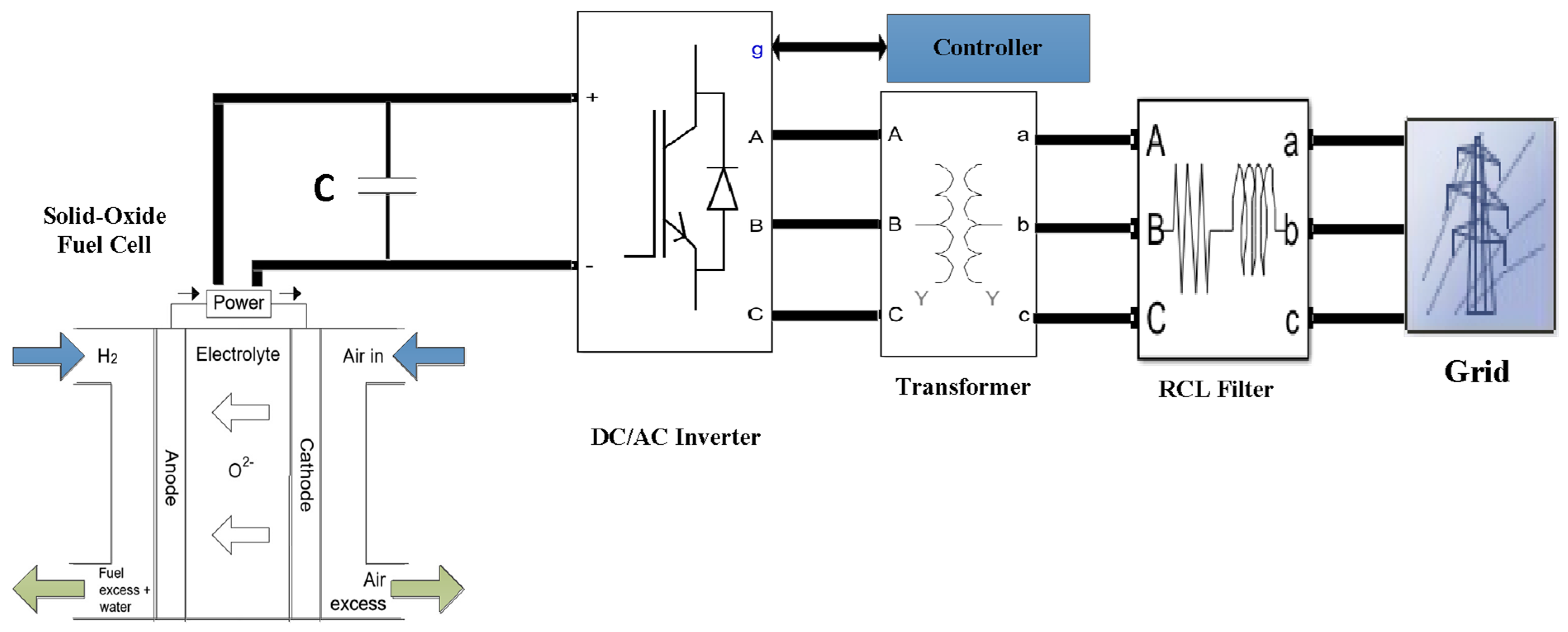
2. The System Description of Solid-Oxide Fuel Cell with Grid Connection

The grid connection system of the SOFC is shown in Figure 1. The system consists of solid-oxide fuel cell generation, a DC/AC three-phase inverter, a controller, and a connected phase grid.

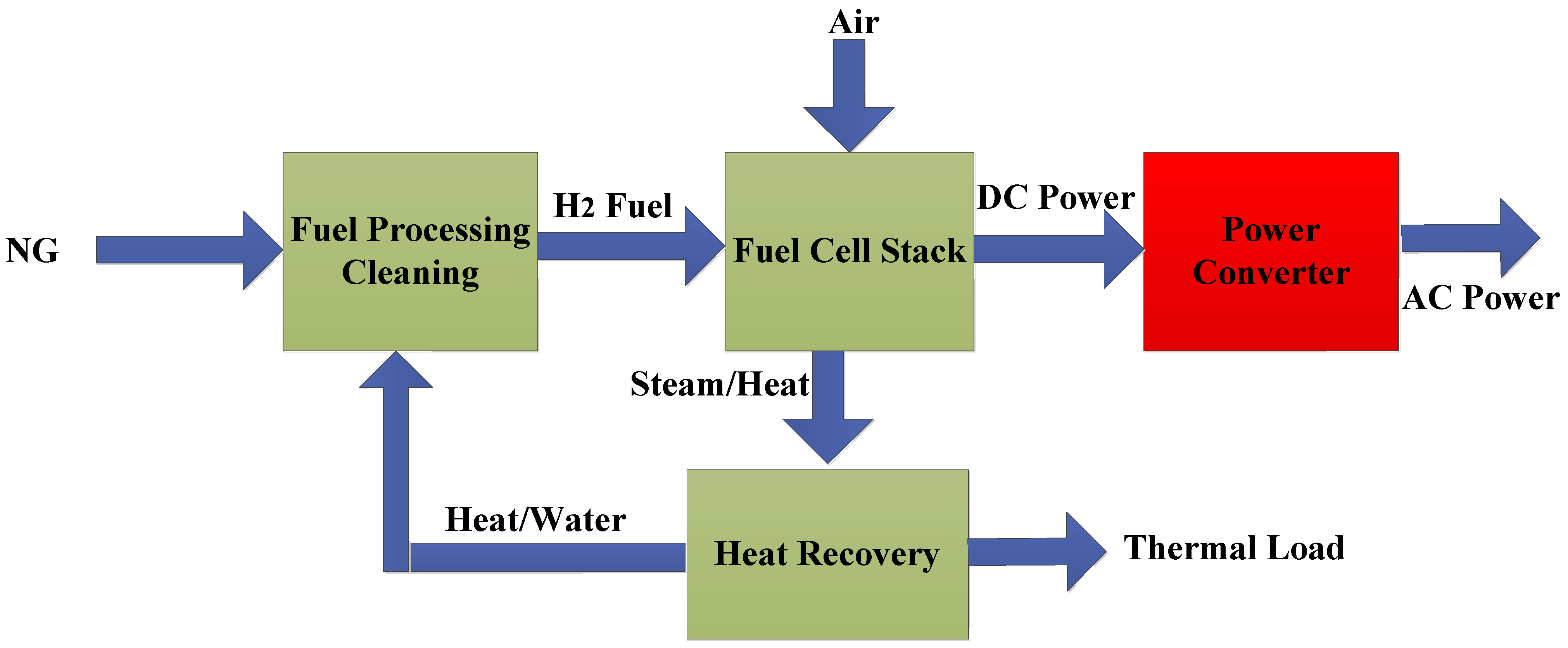
2.1. Solid-Oxide Fuel Cell

A solid-oxide fuel cell (SOFC) is one of the promising renewable energy resources that has been studied in the last few decades, where several studies have focused on enhancing its performance while connected to the grid. Ideally, a single SOFC operating at open-circuit voltage exhibits a potential of 1 V. Under load, this voltage typically ranges from 0.5 to 0.7 V. The current density varies significantly, from 200 to 1000 mA/cm2, which also depends on the cell’s material composition, design, and operating conditions. To achieve higher voltage and current outputs for practical applications, multiple cells are interconnected in series and parallel configurations to form a stack [22]. A complete SOFC power system, beyond the fuel cell stack itself, includes several essential subsystems [23]. These main subsystems can be summarized (as shown in Figure 2) as a fuel processing and cleaning unit (to remove contaminants and harmful substances that may cause damage to the fuel cell components), an air supply section (to provide oxygen to the stack), a power conditioning unit (DC/AC conversion to meet the end-user load requirements), a thermal management system (to maintain the required operating temperature of the fuel cell), and a comprehensive control and safety subsystem.
The operation of a SOFC involves three primary input gases: hydrogen (H2), water vapor (H2O), and oxygen (O2). These input gases react with the electrode materials (the anode and the cathode). Common materials include nickel-impregnated yttria-stabilized zirconia (8 mol% Y2O3-ZrO2, or 8-YSZ/Ni) for the anode, yttria-stabilized zirconia (YSZ) as the electrolyte, and lanthanum strontium manganite (La0.8Sr0.2MnO3, or LSM) for the cathode [24]. Standard SOFCs typically require operating temperatures exceeding 800 °C to ensure effective electrolyte and electrode performance [25]. The anode plays a crucial role in SOFCs [26] by catalyzing the fuel oxidation reaction (see Equation (1)). Similarly, the cathode is essential for its catalytic activity in the oxygen reduction reaction (Equation (2)). Figure 2 illustrates a schematic of an SOFC power plant, where the primary fuel cell generation components (stack, oxygen, and air supplies) are connected to a DC-AC inverter for grid-connected applications [27].
H 2 + O 2 H 2 O + 2 e
1 2 O 2 + 2 e O 2

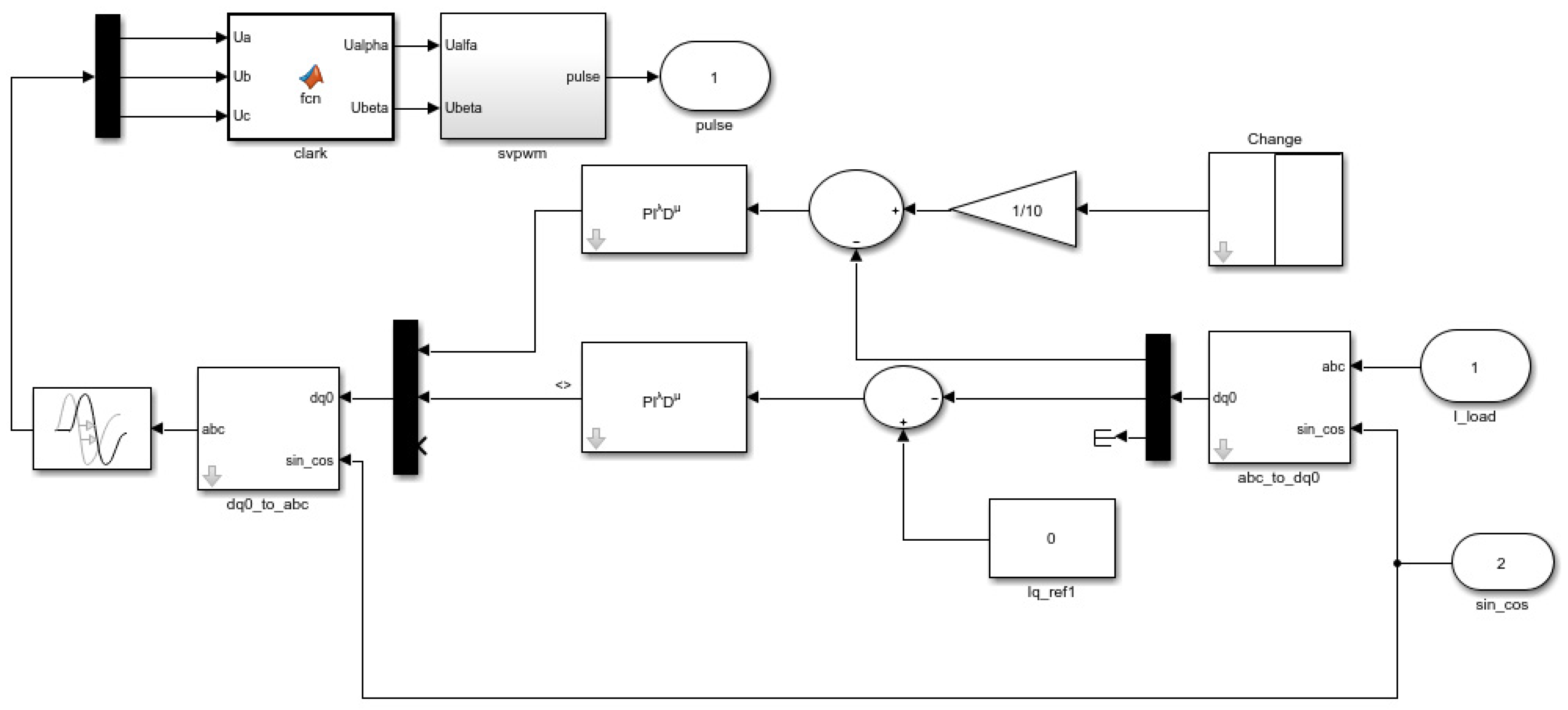
2.2. Control in Inverter

Usually, controllers are employed in three-phase inverters to convert DC power to AC power for the grid. Several research works have suggested the utilization of an IGBT bridge inverter while implementing a PID controller. To optimize the controller gains, usually, different types of optimization techniques can be employed to perform the parameter tuning and achieve the best performance. In this work, an FOPID controller is used to improve the inverter performance compared to the basic “classic PID” controller. The equation for the PID controller is presented in Equation (3), and Figure 3 illustrates the controller’s block diagram, showing the phase-locked loop (PLL), dq-axis transformation, and the time values for the repeating table (likely a parameter that changes) within the controller, which influences the current controller’s response [28].
G s = K p + K i s + S K d

Fractional-Order PID

The fractional-order proportional–integral–derivative (FOPID) controller has attracted significant attention and has seen growing application in diverse control systems over the past few decades, where the FOPID controller is a remarkable enhancement of the traditional PID controller. Figure 4 shows the structure block diagram of the FOPID controller [12]. By including two additional parameters more than the PID controller, the FOPID may increasingly add more complications to the tuning processes of the controller, yet it provides more opportunities to deal with systems with dynamic complexities.
The extra two parameters are the λ term, which is used in a fractional-order integration, and the µ term used in a fractional-order derivation. Therefore, extending the possibilities of obtaining better results for inverters controlling steps [29]. These two parameters are contingent on fundamental operation, denoted as D t α a , where a and t represent the limits of the process, and α ϵ   R [5]. A continuous integral process is defined in Equation (4).
D t α a =                                   d α d t α :   α > 0 ,                   1                       :   α = 0 , a t d Γ : α < 0 .
For the sake of a simplified differentiation and integration, the parameters a and t represent the operational boundaries. The Gamma function is defined in Equation (5):
Γ n = 0 t n 1 e t d t .
This function is a generalization of the factorial in Equation (6):
Γ   n = n 1 Γ n 1
Numerous definitions for fractional differentiation have been proposed. The following equations illustrate the fundamental calculations involved in fractional calculus:
  • The Riemann–Liouville (R-L) description:
D t α a ƒ ( t ) = 1 Γ n α d n d t n a t f ( τ ) ( t τ ) ( α n + 1 ) d t
where ƒ (t) is a function supposed to be satisfactorily flat and nearly integrable. Γ(.) is the gamma function for ( n 1 < α < n ) .
2.
The description of Grunwald–Letnikov (G-L) is shown in Equation (8):
D α f ( t ) = l i m Δ t 0   1 Δ t α k = 0   ( 1 ) k α k f t k Δ t
where ( α k ) is a coefficient of binomial which can be assigned as follows:
α k = α α 1 α 2 α k + 1 k !
3.
The Caputo definition is given by:
D t α a ƒ ( t ) = 1 Γ n α a t ƒ n τ t τ ( α n + 1 ) d t .
Among the aforementioned three definitions, the most commonly used is the Riemann–Liouville (R-L) definition. The Caputo definition and R-L definition are almost the same, except for some initial value settings. Next, the Laplace Transform (while zero original conditions are considered) is obtained as follows:
L D t α a ƒ ( t ) = s ± α s λ F ( s ) , s µ F ( s )   0 < λ < 1 ,   0 < µ < 1
The adjustment between PID control and FOPID control can be summarized with the two parameters λ and µ, which are fractions rather than an integer and derivative. FOPID control is obtained as described in Equation (12):
G s = u ( s ) e ( s ) = K p + K i s λ + K d S µ

3. Optimization Techniques

3.1. Beluga Whale Optimization

The beluga whale optimization (BWO) represents a novel swarm-based optimization technique that emulates the behavior of beluga whales (BWs) during hunting, swimming, and whale fall activities. The exploitation and exploration phases of the BWO algorithm were inspired by the swimming, hunting, and whale fall processes of the BWs [30]. The BWO is mathematically modeled as follows:
Initialization: The initial locations of the BWs can be represented as follows:
X j i = L b j + U b j L b j × r a n d
The process of the BWO emulates the swimming activities of two pairs of beluga whales, which can be represented as follows:
X i , j t + 1 = X i , p j t + X r , p 1 t X i , p j t 1 + r 1 s i n 2 π r 2 , j = even   X i , p j t + X r , p 1 t X i , p j t 1 + r 1 c o s 2 π r 2 , j = odd  
where r 1 and r 2 are random values. X r , p 1 t represents a randomly selected BW’s location.
The BWO’s exploitation phase simulates the hunting mechanism of the BWs, where the BWs charge the information about the best food location. This phase is based on updating the locations of the BWs using the Levy flight motion. The mathematical exploitation phase of the BW is represented as follows:
X i t + 1 = r 3 X best   t r 4 X i t + C 1 L F X r t X i t
In which
C 1 = 2 r 4 1 t / t m a x
L F = 0.05 × u × σ | v | 1 / β
where
σ = Γ ( 1 + β ) × s i n ( π β / 2 ) Γ ( ( 1 + β ) / 2 ) × β × 2 ( β 1 ) / 2 1 / β
where r 3 and r 4 denote random values. u and v refer to random values obtained from the normal distribution. β is a constant equal to 1.5. To ensure the transition between the BW phases, an adaptive operator β f is used and obtained as follows:
β f = β 0 1 t / 2 t m a x
where β 0 represents a random value in the range [0–1]. The final stage of the BWO algorithm is the fall ball, and it can be represented as follows:
X i t + 1 = r 5 X i t r 6 X r t + r 7 X step  
where r 5 , r 6 , and r 7 represent random numbers. X step   is calculated as follows:
X step   = u b l b exp C 2 t t m a x
where u b and l b are the upper and the lower limits of the decision variables. C 2 refers to a time-varying factor that is calculated as follows:
C 2 = 2 W f × n
In which
W f = 0.1 0.05 t t m a x
where n is the population size. Figure 5 shows the flowchart that describes the application of the BWO algorithm to tune the FOPID controller parameters.

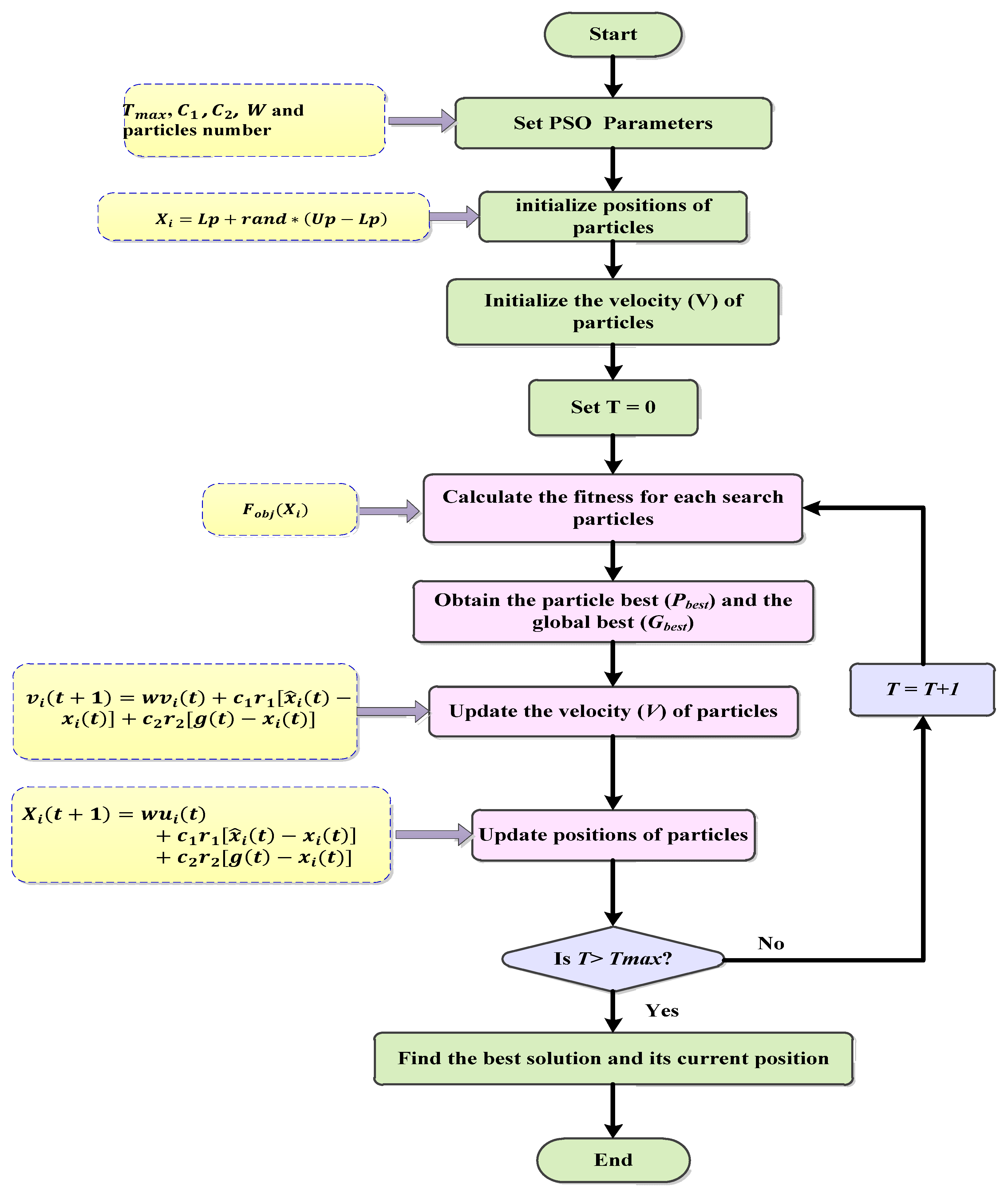
3.2. Particle Swarm Optimization

The particle swarm optimization (PSO) algorithm is a nature-inspired optimization algorithm widely used across various research and engineering fields. This algorithm employs a population of candidate solutions, referred to as a swarm, to search for the optimal solution. PSO is a stochastic optimization technique that operates based on a swarm of potential solutions known as particles [31]. The PSO algorithm comprises three main steps: evaluating the fitness of each particle, updating the individual and global best positions, and subsequently updating the velocity and position of each particle. These steps are iteratively repeated until a predefined stopping criterion is met. Figure 6 illustrates the flowchart of the PSO algorithm, providing further details on the particle swarm optimization methodology [32,33]. The velocity of each individual particle is updated according to the following equations [34,35]:
X i t + 1 = w u i t + c 1 r 1 x ^ i t x i t + c 2 r 2 g t x i t
where, 0 c 1 , c 2 2 , ( 0 r 1 , r 2 1)
v i t + 1 = w v i t + c 1 r 1 x ^ i t x i t + c 2 r 2 g t x i t
An individual particle’s position stays known as described in Equation (26):
x i t + 1 = x i t + v i t + 1
The PSO algorithm is an advanced optimization method used to solve complex engineering problems. This optimizer obtains the best solution in FCs with grid connections [36,37,38]. To improve the diversity of particles in the algorithm population and avoid local extremum phenomena, the Lévy flight strategy is integrated with the PSO algorithm. Lévy flight is a random walk method that integrates short-distance search and occasional long-distance walk. It is a non-Gaussian random process whose walking length obeys a Lévy distribution. To improve the random size of PSO algorithms, the PSO algorithm’s particle positions are updated as follows (with α as a random number for the sizing step and u and v are randomly drawn from the normal distribution):
X t + 1 = X t + α L e v y β
X t + 1 = X t + r a n d o m ( s i z e ( D ) ) L e v y ( β )
S = r a n d o m ( s i z e ( D ) ) L e v y ( β ) ~ 0.01 u v 1 β ( x j t g b e s t t )
u ~ N ( 0 , δ u 2 )   v ~ N ( 0 , δ v 2 )

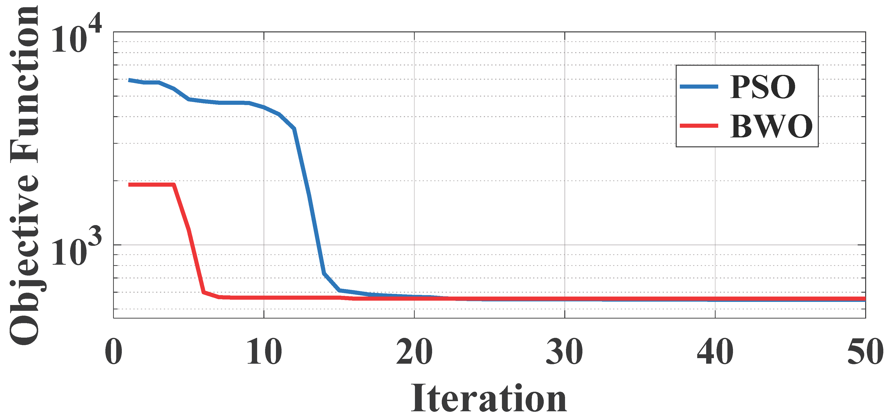
4. Simulation Results and Discussion

In this section, a numerical simulation of solid-oxide fuel cells (SOFCs) under two different conditions is performed where an active power controller controls the inverter’s current based on FOPID while the controller parameters are tuned with natural-inspired algorithms. Table 1 provides all solid-oxide fuel cell system parameters required for the simulation.

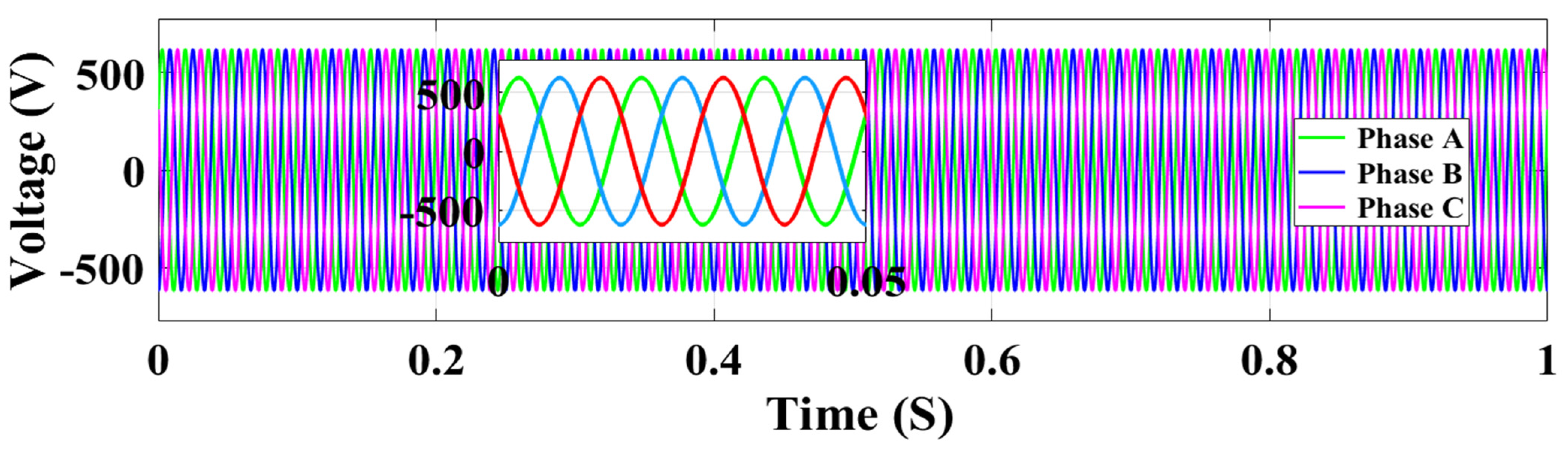
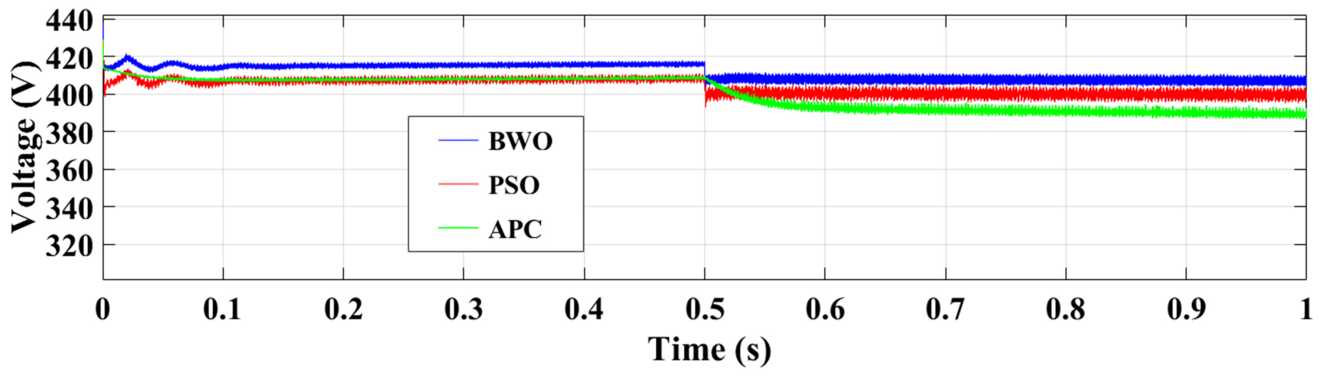
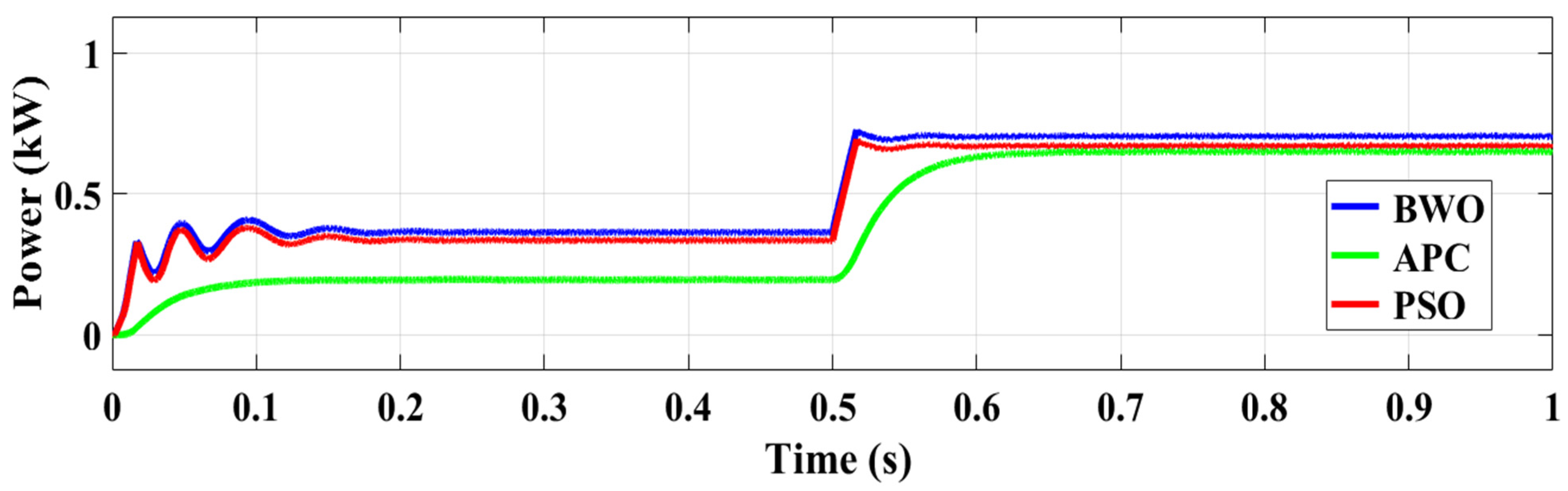
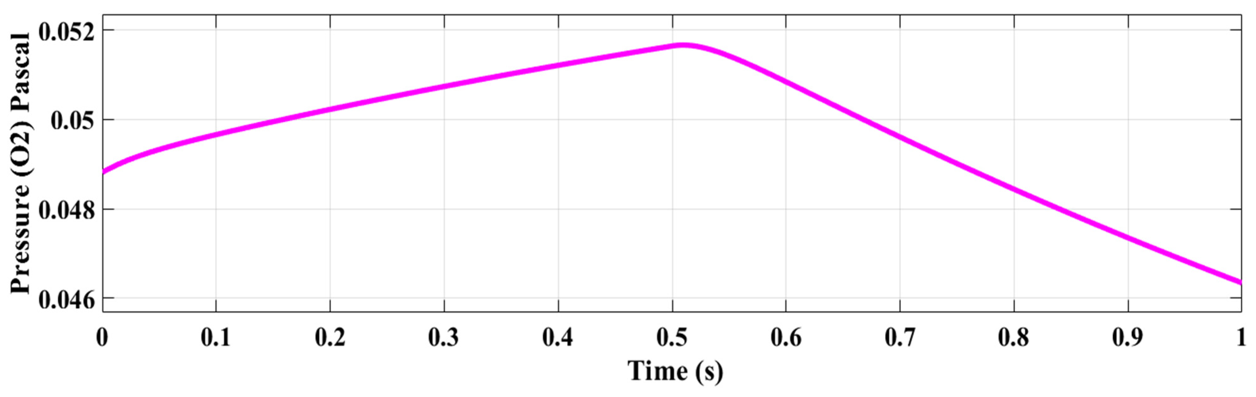
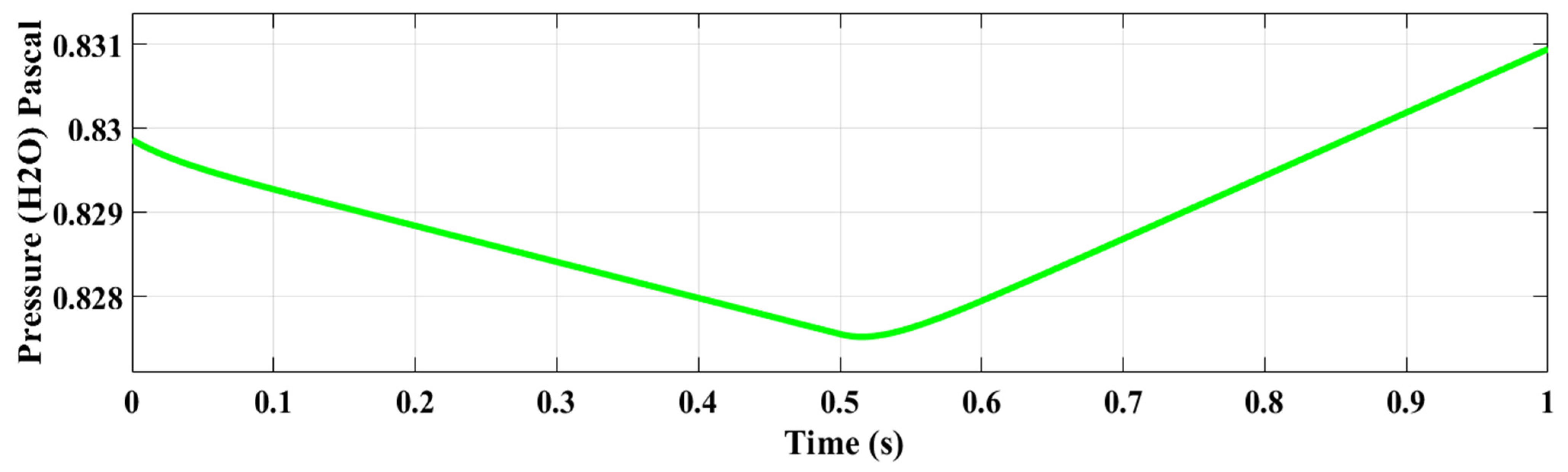
4.1. Scenario 1: Simulation Under a Steady Reference Current Controller

In this study, the current reference for the control process was chosen to be more stable, featuring only two levels (50 A and 100 A). The proposed fractional-order PID (FOPID) controller, tuned using both the beluga whale optimization (BWO) and particle swarm optimization (PSO) algorithms, is compared with an active power controller for managing the inverter. Note that Table 2 provides the optimum values of the FOPID controller’s parameters obtained by both BWO and PSO algorithms, while Table 3 shows the upper and lower values of the FOPID’s parameters which are considered while performing the optimization to generate the BWO and PSO initial search population. Figure 7 illustrates the objective function variations of the BWO and PSO algorithms during the tuning of the FOPID parameters. Both nature-inspired algorithms were executed for 50 iterations with a search population of 20 particles to find the optimal solutions. As evident in Figure 7, the BWO algorithm yielded a lower objective function value compared to PSO, indicating a superior result. This outcome suggests that the BWO algorithm provided a better solution for tuning the FOPID controller within the grid-connected SOFC inverter. In addition, the BWO algorithm starts converging to the best solution within the first 6 iterations, while it took more than 15 iterations for the PSO algorithm to start converging to the optimum solution.
The performance of the FOPID controller in the SOFC grid-connected inverter, tuned by these two algorithms, was compared against an active power controller for managing the inverter of this system. Figure 8 displays the output voltage of the grid connection, 600 volts. Figure 9 illustrates the reference current control in the SOFC connected to the grid. In addition, Figure 10 and Figure 11 present the output current from the SOFC when the inverter is controlled by the FOPID controller tuned with the BWO and PSO algorithms, respectively, with zoomed-in views for the time interval of 0.4 to 0.6 s. Figure 12 shows the output current to the grid using active power control (APC), also including a zoomed-in view for the time interval of 0.4 to 0.6 s.
Observing Figure 12, the APC method takes a longer duration (from 0.5 to 0.6 s) to adjust to the changing current in response to the current reference, compared to the advanced FOPID based on BWO and PSO algorithms, which can be easily verified from Figure 10 and Figure 11. In addition, the active power controller (APC) method demonstrates less effective control performance in the SOFC inverter. In contrast, the BWO and PSO algorithms, as shown in Figure 10 and Figure 11, yield good results and exhibit a suitable response to changes in the reference current, as represented in Figure 9. This performance is notably better than that of the classic APC shown in Figure 12. As a result, Figure 8, Figure 9, Figure 10, Figure 11 and Figure 12 show the output current and voltage for the three controllers. The improved BWO algorithm provides the best solution for current control when using the BWO-based FOPID controller in the inverter within the grid-connected SOFC system.
Figure 13 illustrates the DC voltage of the SOFC under the three different controllers. Figure 14 shows the DC current output from the SOFC, and Figure 15 displays the power generated by the SOFC under the APC approach and FOPID based on BWO and PSO algorithms. Based on the current and voltage profiles presented in these figures, the BWO algorithm applied to tune the FOPID controller parameters in the inverter produces the most favorable current, voltage, and power values from the grid-connected SOFC. Figure 16 describes the active power output from the SOFC, where the advanced BWO algorithm demonstrates good performance in meeting the power demand of the grid, outperforming the APC and PSO-based FOPID controllers. Figure 17 shows the per-unit output voltage of the SOFC under the three controllers, with the BWO-based FOPID technique exhibiting acceptable results. Overall, the BWO algorithm proves to be more responsive in determining the optimal gains for the FOPID controller compared to PSO within the same FOPID framework and in comparison, to the APC method. Figure 18, Figure 19 and Figure 20 show the observed pressures of H2, O2, and H2O within the SOFC, respectively.

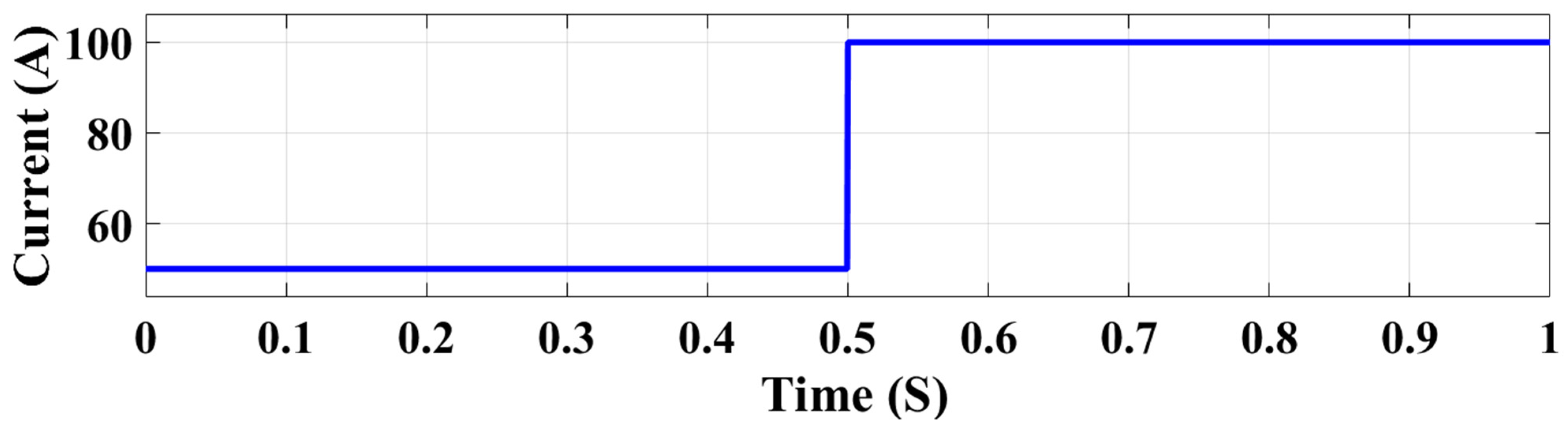
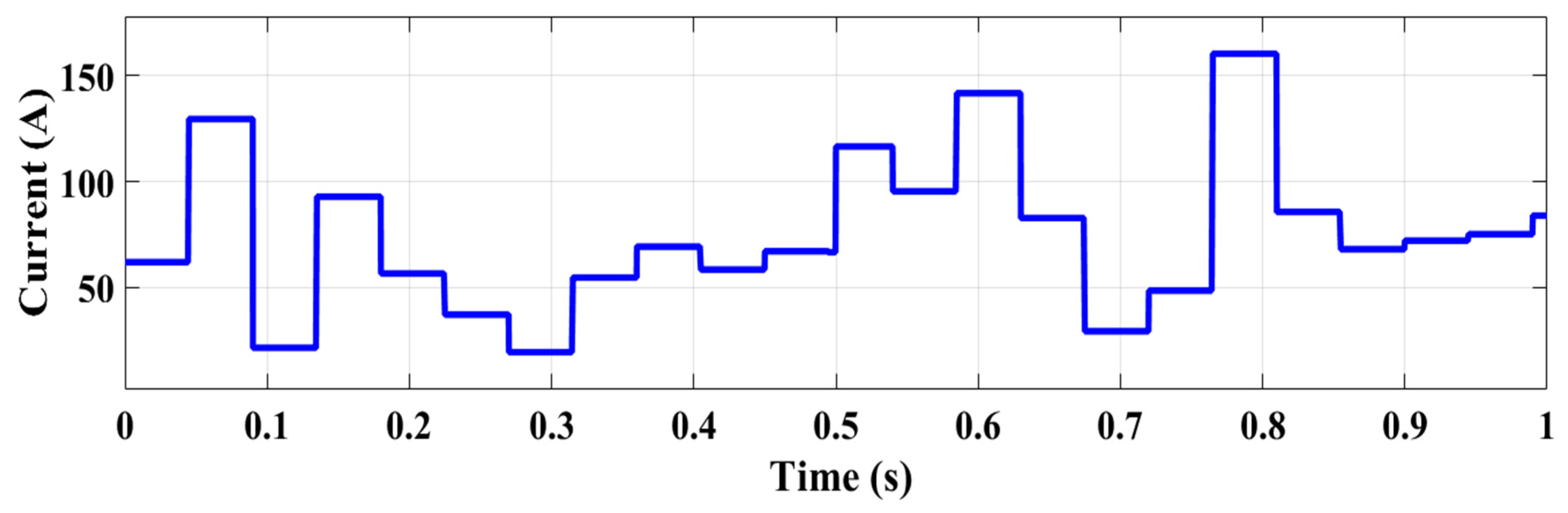
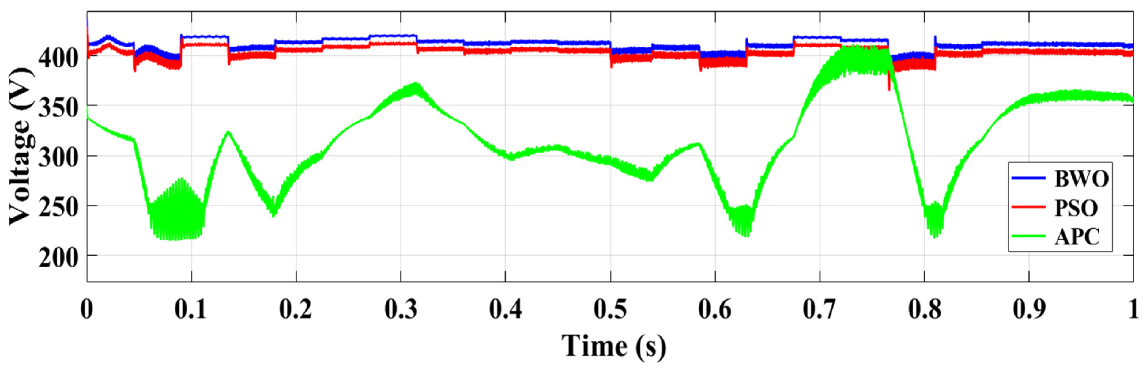
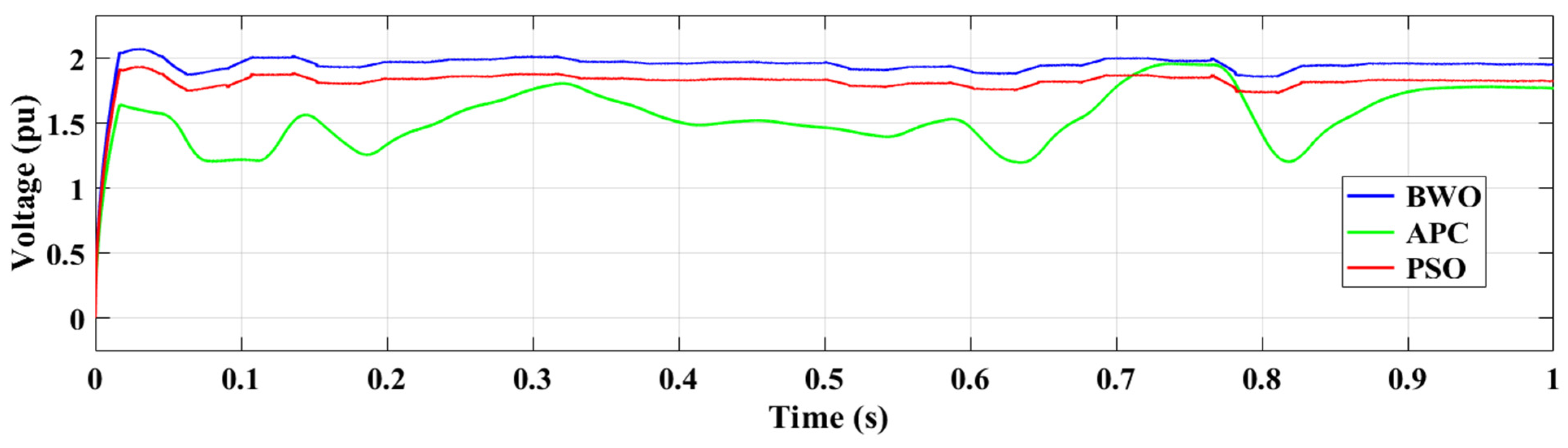
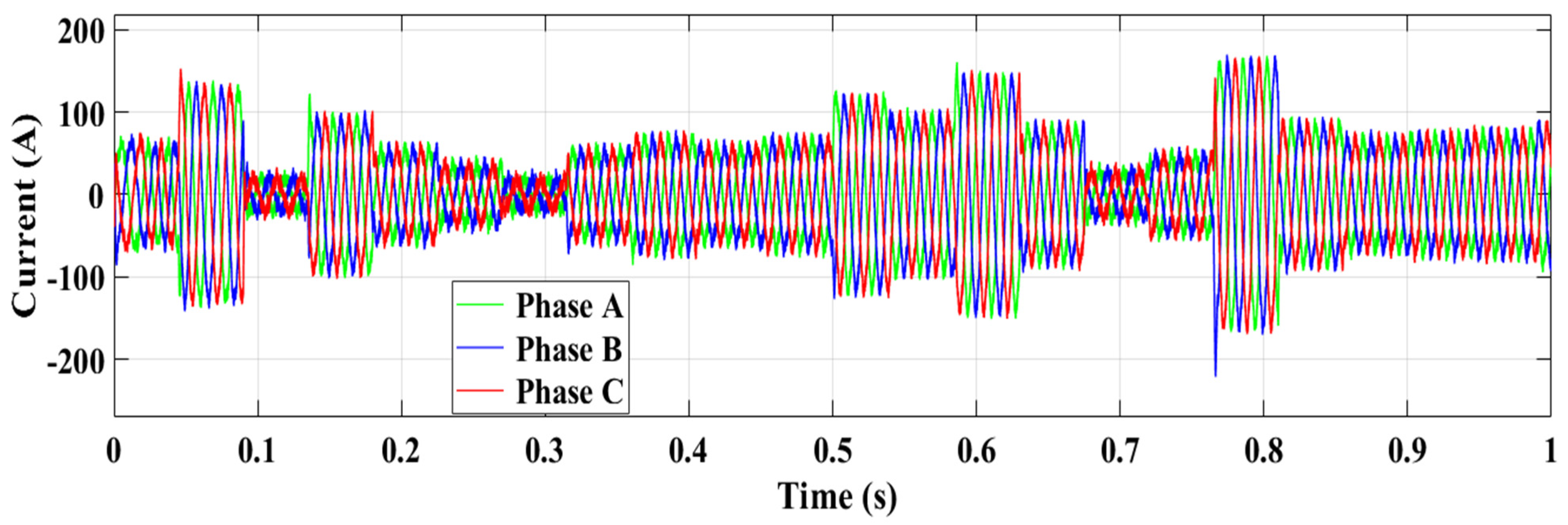
4.2. Scenario 2: Simulation Under a Random Current Controller Changes

Figure 21 illustrates the reference current in the current control system exhibiting multiple random changes between 20 A and 160 A. Figure 22 shows the DC voltage of the SOFC under this random reference current control using the BWO-based FOPID controller, PSO-based FOPID controller, and APC approach. In addition, the DC current of the SOFC resulting from the three different controlling methods is described in Figure 23. Figure 24 presents the per-unit output voltage of the SOFC, while Figure 25 shows the power output from the SOFC under the random reference for the three control techniques. Figure 26 displays the output grid voltage under the random current reference. Figure 27 shows the output grid current when using the APC approach, while Figure 28 and Figure 29 show the output grid current when PSO-based FOPID and BWO-based FOPID controllers, respectively.
Based on the results presented in Scenario 2 involving a reference current with random multiple changes, the APC demonstrates a poor performance across all the system outputs of the grid-connected SOFC. Consistent with previous findings, the BWO algorithm exhibits a more responsive behavior in determining the optimal gains for the FOPID controller compared to PSO within the same FOPID framework and in comparison to APC.
In addition, the APC exhibits significant overshooting at every step change (0.1 s, 0.3 s, 0.6 s, 0.7 s, and 0.8 s). However, the optimized fractional-order PID (FOPID) controller using PSO delivers better current control performance, while the advanced FOPID tuned by the BWO technique provides the best solution for output current, voltage, and power regulation.
Figure 27, Figure 28 and Figure 29 compare the grid output current obtained using the three techniques. The results show that the conventional APC performs poorly, whereas the BWO-based FOPID controller responds quickly and effectively to random current fluctuations. Ultimately, the proposed BWO algorithm demonstrates superior performance in current control when applied to the FOPID-controlled inverter within the grid-connected SOFC system.

5. Conclusions

In this paper, a fractional-order PID (FOPID) controller is used to control a SOFC inverter to enhance its performance. The beluga whale optimization (BWO) algorithm was proposed to determine the optimal controller gains, and the resulting performance was compared with that obtained using the particle swarm optimization (PSO)-based FOPID approach and active power control (APC) method. In the first scenario, the simulation results demonstrated a considerable improvement in the quality of the produced power with the optimally tuned FOPID parameters using BWO, providing the best solution for this grid-connected SOFC system and exhibiting better input and output characteristics. In comparison to the PSO-based FOPID and APC approaches, the BWO-based FOPID controller showed improvements in voltage, current, and generated active and reactive power, outperforming the PSO-based FOPID control and yielding superior results compared to APC. The second scenario compared the three techniques under multiple random changes in the reference current controller. The results consistently showed that BWO-tuned FOPID provided the best performance for the grid-connected SOFC system, while APC exhibited poor control.
In conclusion, the improved FOPID controller, with gains optimized by the two different algorithms, led to an increase in the quality of energy generation and transmission from the SOFC to the grid. When comparing current control, the two modified algorithms effectively pursued the reference current, whereas APC showed poor control performance with a noticeable delay of approximately 10%. Based on these findings, the proposed algorithms within the FOPID controller offer a viable solution for controlling the grid-connected SOFC system.

Author Contributions

Conceptualization, I.B. and A.M.E.-R.; methodology, M.M., I.B., M.E. and A.M.E.-R.; software, M.M.; validation, M.M., I.B. and A.M.E.-R.; investigation, I.B., M.E. and A.M.E.-R.; writing—original draft, M.M. and M.E.; writing—review and editing, I.B., M.E. and A.M.E.-R.; supervision, I.B., M.E. and A.M.E.-R.; project administration, M.E. All authors have read and agreed to the published version of the manuscript.

Funding

This research received no external funding.

Data Availability Statement

The original contributions presented in this study are included in the article. Further inquiries can be directed to the corresponding authors.

Conflicts of Interest

The authors declare no conflict of interest.

Abbreviations

Symbols and Abbreviations
iparticle indexr3, r4denote the number of randoms
winertial coefficientu and vrefer to random values obtained from the normal distribution
c1, c2hastening constantsΒa constant equal to 1.5
r1, r2random values r 5 , r 6 and r 7 Represent random numbers
v i   (t)particle’s velocity B 0 Represents a random value in the range [0–1].
x i   (t)position particle’s X r , p 1 t represents a randomly selected BW’s location
x ^ i   (t)particle in best solution λ a fractional-order integration
g(t)swarm in best solution µ a fractional-order derivation
Acronyms
PSOParticle Swarm Optimization
FCsFuel Cell
FOPIDFractional-Order Proportion–Integral–Derivative
SOFCSolid-Oxide Fuel Cell
APCActive Power Controller
BWOBeluga Whale Optimization
RCCReference Current Control

References

  1. Giddey, S.; Badwal, S.P.S.; Kulkarni, A.; Munnings, C. A comprehensive review of direct carbon fuel cell technology. Prog. Energy Combust. Sci. 2012, 38, 360–399. [Google Scholar] [CrossRef]
  2. Badwal, S.P.S.; Giddey, S.; Munnings, C.; Kulkarni, A. Review of progress in high temperature solid oxide fuel cells. J. Aust. Ceram. Soc. 2015, 50, 23–37. [Google Scholar]
  3. Han, Y.; Li, H.; Shen, P.; Coelho, E.A.A.; Guerrero, J.M. Review of active and reactive power sharing strategies in hierarchical controlled microgrids. IEEE Trans. Power Electron. 2016, 32, 2427–2451. [Google Scholar] [CrossRef]
  4. Xia, Y.; Shimomura, M.; Paserba, J. Active power control for preventing voltage instability using an adjustable speed machine. In 2001 Power Engineering Society Summer Meeting. IEEE Conf. Proc. 2001, 2, 866–871. [Google Scholar]
  5. Ranganayakulu, R.; Babu, G.U.B.; Rao, A.S.; Patle, D.S. A comparative study of fractional order PIλ/PIλDµ tuning rules for stable first order plus time delay processes. Resour.-Effic. Technol. 2016, 2, S136–S152. [Google Scholar] [CrossRef]
  6. Nataraj, D.; Subramanian, M. Design and optimal tuning of fractional order PID controller for paper machine headbox using jellyfish search optimizer algorithm. Sci. Rep. 2025, 15, 1631. [Google Scholar] [CrossRef]
  7. Saleh, B.; Yousef, A.M.; Ebeed, M.; Abo-Elyousr, F.K.; Elnozahy, A.; Mohamed, M.; Abdelwahab, S.A.M. Design of PID controller with grid-connected hybrid renewable energy system using optimization algorithms. J. Electr. Eng. Technol. 2021, 16, 3219–3233. [Google Scholar] [CrossRef]
  8. Masadeh, R.; Alsharman, N.; Sharieh, A.; Mahafzah, B.A.; Abdulrahman, A. Task scheduling on cloud computing based on sea lion optimization algorithm. Int. J. Web Inf. Syst. 2021, 17, 99–116. [Google Scholar] [CrossRef]
  9. Ranganayakulu, R.; Uday Bhaskar Babu, G.; Seshagiri Rao, A. Fractional filter IMC-PID controller design for second order plus time delay processes. Cogent Eng. 2017, 4, 1366888. [Google Scholar] [CrossRef]
  10. Zamani, M.; Karimi-Ghartemani, M.; Sadati, N.; Parniani, M. Design of a fractional order PID controller for an AVR using particle swarm optimization. Control Eng. Pract. 2009, 17, 1380–1387. [Google Scholar] [CrossRef]
  11. Padula, F.; Visioli, A. On the fragility of fractional-order PID controllers for FOPDT processes. ISA Trans. 2016, 60, 228–243. [Google Scholar] [CrossRef]
  12. Padula, F.; Visioli, A. Tuning rules for optimal PID and fractional-order PID controllers. J. Process Control 2011, 21, 69–81. [Google Scholar] [CrossRef]
  13. Wang, W.; Su, C.; Wu, Y.; Ran, R.; Shao, Z. Progress in solid oxide fuel cells with nickel-based anodes operating on methane and related fuels. Chem. Rev. 2013, 113, 8104–8151. [Google Scholar] [CrossRef]
  14. Haddad, A.; Ramadan, M.; Khaled, M.; Ramadan, H.; Becherif, M. Study of hybrid energy system coupling fuel cell, solar thermal system and photovoltaic cell. Int. J. Hydrogen Energy 2020, 45, 13564–13574. [Google Scholar] [CrossRef]
  15. Wachsman, E.D.; Lee, K.T. Lowering the temperature of solid oxide fuel cells. Science 2011, 334, 935–939. [Google Scholar] [CrossRef] [PubMed]
  16. Madaci, B.; Chenni, R.; Kurt, E.; Hemsas, K.E. Design and control of a stand-alone hybrid power system. Int. J. Hydrogen Energy 2016, 41, 12485–12496. [Google Scholar] [CrossRef]
  17. Cao, J.Y.; Liang, J.; Cao, B.G. Optimization of fractional order PID controllers based on genetic algorithms. In Proceedings of the 2005 International Conference on Machine Learning and Cybernetics IEEE, Guangzhou, China, 18–21 August 2005; Volume 9, pp. 5686–5689. [Google Scholar]
  18. Verma, S.K.; Yadav, S.; Nagar, S.K. Optimization of fractional order PID controller using grey wolf optimizer. J. Control Autom. Electr. Syst. 2017, 28, 314–322. [Google Scholar] [CrossRef]
  19. Zhao, D.; Li, F.; Ma, R.; Zhao, G.; Huangfu, Y. An unknown input nonlinear observer based fractional order PID control of fuel cell air supply system. IEEE Trans. Ind. Appl. 2020, 56, 5523–5532. [Google Scholar] [CrossRef]
  20. Fathy, A.; Rezk, H.; Alanazi, T.M. Recent approach of forensic-based investigation algorithm for optimizing fractional order PID-based MPPT with proton exchange membrane fuel cell. IEEE Access 2021, 9, 18974–18992. [Google Scholar] [CrossRef]
  21. Silaa, M.Y.; Barambones, O.; Derbeli, M.; Napole, C.; Bencherif, A. Fractional order PID design for a proton exchange membrane fuel cell system using an extended grey wolf optimizer. Processes 2022, 10, 450. [Google Scholar] [CrossRef]
  22. Da Silva, F.S.; de Souza, T.M. Novel materials for solid oxide fuel cell technologies: A literature review. Int. J. Hydrogen Energy 2017, 42, 26020–26036. [Google Scholar] [CrossRef]
  23. Wang, J.; Lam, K.Y.; Saccoccio, M.; Gao, Y.; Chen, D.; Ciucci, F. Ca and In co-doped BaFeO3−δ as a cobalt-free cathode material for intermediate-temperature solid oxide fuel cells. J. Power Sources 2016, 324, 224–232. [Google Scholar] [CrossRef]
  24. Jung, G.B.; Chang, C.T.; Yeh, C.C.; Nguyen, X.V.; Chan, S.H.; Lin, C.Y.; Yu, J.W.; Lee, W.T.; Chang, S.W.; Kao, I.C. Study of reversible solid oxide fuel cell with different oxygen electrode materials. Int. J. Hydrogen Energy 2016, 41, 21802–21811. [Google Scholar] [CrossRef]
  25. Wang, S.F.; Hsu, Y.F.; Chang, J.H.; Cheng, S.; Lu, H.C. Characteristics of Cu and Mo-doped Ca3Co4O9−δ cathode materials for use in solid oxide fuel cells. Ceram. Int. 2016, 42, 11239–11247. [Google Scholar] [CrossRef]
  26. Shaikh, S.P.; Muchtar, A.; Somalu, M.R. A review on the selection of anode materials for solid-oxide fuel cells. Renew. Sustain. Energy Rev. 2015, 51, 1–8. [Google Scholar] [CrossRef]
  27. Boldrin, P.; Brandon, N.P. Progress and outlook for solid oxide fuel cells for transportation applications. Nat. Catal. 2019, 2, 571–577. [Google Scholar] [CrossRef]
  28. Elnozahy, A.; Yousef, A.M.; Abo-Elyousr, F.K.; Mohamed, M.; Abdelwahab, S.A.M. Performance improvement of hybrid renewable energy sources connected to the grid using artificial neural network and sliding mode control. J. Power Electron. 2021, 21, 1166–1179. [Google Scholar] [CrossRef]
  29. Podlubny, I. Fractional-order systems and PI/sup/spl lambda//D/sup/spl mu//-controllers. IEEE Trans. Autom. Control 1999, 44, 208–214. [Google Scholar] [CrossRef]
  30. Zhong, C.; Li, G.; Meng, Z. Beluga whale optimization: A novel nature-inspired metaheuristic algorithm. Knowl.-Based Syst. 2022, 251, 109215. [Google Scholar] [CrossRef]
  31. Zhang, Y.; Wang, S.; Ji, G. A comprehensive survey on particle swarm optimization algorithm and its applications. Math. Probl. Eng. 2015, 1, 931256. [Google Scholar] [CrossRef]
  32. Ahmadi, S.; Abdi, S.; Kakavand, M. Maximum power point tracking of a proton exchange membrane fuel cell system using PSO-PID controller. Int. J. Hydrogen Energy 2017, 42, 20430–20443. [Google Scholar] [CrossRef]
  33. Said, M.; El-Rifaie, A.M.; Tolba, M.A.; Houssein, E.H.; Deb, S. An Efficient Chameleon Swarm Algorithm for Economic Load Dispatch Problem. Mathematics 2021, 9, 2770. [Google Scholar] [CrossRef]
  34. Haklı, H.; Uğuz, H. A novel particle swarm optimization algorithm with Levy flight. Appl. Soft Comput. 2014, 23, 333–345. [Google Scholar] [CrossRef]
  35. Abualigah, L.; Sheikhan, A.; Ikotun, A.M.; Zitar, R.A.; Alsoud, A.R.; Al-Shourbaji, I.; Hussien, A.G.; Jia, H. Particle swarm optimization algorithm: Review and applications. In Metaheuristic Optimization Algorithms; Elsevier: Amsterdam, The Netherlands, 2024; pp. 1–14. [Google Scholar] [CrossRef]
  36. Diab, A.A.Z.; Tolba, M.A.; El-Magd, A.G.A.; Zaky, M.M.; El-Rifaie, A.M. Fuel cell parameters estimation via marine predators and political optimizers. IEEE Access 2020, 8, 166998–167018. [Google Scholar] [CrossRef]
  37. Alnami, H.; El-Rifaie, A.M.; Moustafa, G.; Hakmi, S.H.; Shaheen, A.M.; Tolba, M.A. Optimal allocation of TCSC devices in transmission power systems by a novel adaptive dwarf mongoose optimization. IEEE Access 2023, 12, 6063–6087. [Google Scholar] [CrossRef]
  38. Mohamed, M.; El-Rifaie, A.M.; Boulkaibet, I.; Elnozahy, A. Optimal Economic and Environmental Aspects in Different Types of Loads via Modified Capuchin Algorithm for Standalone Hybrid Renewable Generation Systems. Processes 2024, 12, 2902. [Google Scholar] [CrossRef]
Figure 1. Grid-connected SOFC.
Processes 13 02044 g001
Figure 2. Solid-oxide fuel cell power plant schematic.
Processes 13 02044 g002
Figure 3. Block diagram of the control system.
Processes 13 02044 g003
Figure 4. Structure of the FOPID controller.
Processes 13 02044 g004
Figure 5. The flowchart of applying the BWO for the FOPID controller tuning parameters.
Processes 13 02044 g005
Figure 6. Diagram of the PSO algorithm for FOPID controller.
Processes 13 02044 g006
Figure 7. Objective function of BWO and PSO algorithms.
Processes 13 02044 g007
Figure 8. Output grid voltage.
Processes 13 02044 g008
Figure 9. Reference current.
Processes 13 02044 g009
Figure 10. Output current from SOFC obtained by the BWO-based FOPID controller.
Processes 13 02044 g010
Figure 11. Output current from SOFC obtained by the PSO-based FOPID controller.
Processes 13 02044 g011
Figure 12. Output current from SOFC obtained by active power control.
Processes 13 02044 g012
Figure 13. DC voltage of SOFC.
Processes 13 02044 g013
Figure 14. DC current of SOFC.
Processes 13 02044 g014
Figure 15. Power from SOFC.
Processes 13 02044 g015
Figure 16. The SOFC power delivered to the grid.
Processes 13 02044 g016
Figure 17. Output voltage (pu) of SOFC.
Processes 13 02044 g017
Figure 18. H2 pressure in SOFC.
Processes 13 02044 g018
Figure 19. O2 pressure in SOFC.
Processes 13 02044 g019
Figure 20. H2O pressure in SOFC.
Processes 13 02044 g020
Figure 21. Reference current with multiple random levels.
Processes 13 02044 g021
Figure 22. DC voltage of SOFC.
Processes 13 02044 g022
Figure 23. DC current of SOFC.
Processes 13 02044 g023
Figure 24. Output voltage (pu) of SOFC.
Processes 13 02044 g024
Figure 25. Power from SOFC.
Processes 13 02044 g025
Figure 26. Output grid voltage.
Processes 13 02044 g026
Figure 27. Output grid current obtained by the APC.
Processes 13 02044 g027
Figure 28. Output grid current obtained by the PSO-based FOPID Control.
Processes 13 02044 g028
Figure 29. Output grid current obtained by the BWO-based FOPID Control.
Processes 13 02044 g029
Table 1. Parameters of the system components.
ParameterValueUnit
Absolute temperature of SOFC1273K
Original current of SOFC100A
Faraday’s constant of gas 96.487 × 10⁶C/kmol
Common continuous of gas8314J/ kmol K
Perfect ordinary voltage 1.18V
Cells in series450
Fuel maximum use of SOFC0.9
Fuel minimal use of SOFC0.8
Optimum fuel use of SOFC0.85
In case of molar constant, hydrogen value 8.43 × 10⁻⁴(kmol/ (s atm)
In case of molar constant, water value 2.81 × 10⁻⁴(kmol/(s atm)
In case of molar constant, oxygen value 2.52 × 10⁻⁴(kmol/(s atm)
Time response in hydrogen of SOFC26.1s
Time response in water of SOFC78.3s
Time at oxygen flow of SOFC2.91s
Ohmic loss of SOFC3.2813 × 10−0.04Ohm
The response time in an electrical0.8s
fuel processor response time 5s
hydrogen and oxygen ratio/value1.145
Snubber resistance Rs of inverter1 × 105(Ohm)
Power Electronic device of inverter IGBT/Diodes
Ron of Inverter 1 × 10⁻³(Ohm)
Number of bridge arms of inverter3
p-H2 of SOFC0.05
p-H2O of SOFC0.829
p-O2 of SOFC0.0495
Table 2. Parameters of optimization at the FOPID.
ParameterValue
Kp of FOPID controller in d-access at PSO0.0988
Ki of FOPID controller in d-access at PSO67.1347
Kd of FOPID controller in d-access at PSO0.0853
Lambda of FOPID controller in d-access at PSO0.8962
Mu of FOPID controller in d-access at PSO0.1839
Kp of FOPID controller in q-access at PSO0.0995
Ki of FOPID controller in q-access at PSO348.38
Kd of FOPID controller in q-access at PSO0.0720
Lambda of FOPID controller in q-access at PSO0.9900
Mu of FOPID controller in q-access at PSO0.0462
Kp of FOPID controller in d-access at BWO0.09715
Ki of FOPID controller in d-access at BWO52
Kd of FOPID controller in d-access at BWO0.09715
Lambda of FOPID controller in d-access at BWO0.9618
Mu of FOPID controller in d-access at BWO1.0000 × 10−3
Kp of FOPID controller in q-access at BWO0.097154566550583
Ki of FOPID controller in q-access at BWO132.6
Kd of FOPID controller in q-access at BWO0.0971
Lambda of FOPID controller in q-access at BWO0.9618
Mu of FOPID controller in q-access at BWO0.1097
Numerator of APC (1/S)3000
Table 3. Lower/Upper frontiers variables of the control system.
NoParameterLowerUpper
1Kp of FOPID controller in d-access0.0010.1
2Ki of FOPID controller in d-access52600
3Kd of FOPID controller in d-access0.0010.1
4Lambda of FOPID controller in d-access0.0010.99
5Mu of FOPID controller in d-access0.0010.99
6Kp of FOPID controller in q-access0.0010.1
7Ki of FOPID controller in q-access54600
8Kd of FOPID controller in q-access0.0010.1
9Lambda of FOPID controller in q-access0.0010.99
10Mu of FOPID controller in q-access0.0010.99
Disclaimer/Publisher’s Note: The statements, opinions and data contained in all publications are solely those of the individual author(s) and contributor(s) and not of MDPI and/or the editor(s). MDPI and/or the editor(s) disclaim responsibility for any injury to people or property resulting from any ideas, methods, instructions or products referred to in the content.

