1. Introduction
With the deepening of the “dual carbon” goal, the penetration rate of renewable energy represented by wind power and photovoltaics in the power system continues to rise, which has brought great challenges to the stability and flexible regulation of the power grid [
1,
2,
3,
4]. Therefore, the wind-solar complementary system that can effectively solve the instability of single wind power or photovoltaic power generation has gradually become a research hotspot. In addition, the power-to-hydrogen technology can effectively improve the flexibility of the multi-energy system, reduce the impact of the intermittent and volatile wind and solar energy on the stable operation of the system, adjust the imbalance between power generation and power consumption, and achieve efficient energy conversion and storage [
5,
6]. Therefore, it is considered to study the combined system, including the wind-solar complementary system and the hydrogen production system. The key to this research is how to ensure the stable and efficient operation of the microgrid. The use of virtual synchronous generator (VSG) technology can effectively solve this problem [
7,
8].
At present, research on new energy hydrogen production systems and their control strategies at home and abroad has made certain progress. Reference [
9] proposed a photovoltaic electrolysis hydrogen production system that optimizes the electrolysis efficiency of the electrolyzer through a two-stage converter. However, due to the limited experimental verification conditions of the research, it is impossible to fully cover the actual working conditions, and the research results are difficult to apply in practice. Reference [
10] established a model of photovoltaic, electrolyzer, and fuel cell (PEMFC), and proposed an active control strategy based on hydrogen energy storage, but lacked stability research under grid fault conditions. Therefore, whether it can be stably connected to the grid requires more in-depth research. Reference [
11] verified the coordinated control strategy of the wind-hydrogen coupled power generation system through simulation, but did not deeply consider the impact of complex operating conditions on the system. Reference [
12] proposed an impedance model of wind power hydrogen production equipment, analyzed the stability in grid-connected/off-grid mode, and proposed a corresponding simple control strategy, but did not continue to study it in depth. The latest research shows that reference [
13] used digital twin technology to build a real-time simulation platform for the wind-solar-hydrogen storage coupling system, but its virtual inertia compensation algorithm did not consider the multi-time scale dynamic characteristics; the deep learning predictive control strategy proposed in reference [
14] improved the wind-solar output prediction accuracy, but did not form a closed-loop optimization with the hydrogen production load.
In order to cope with the instability of single wind power or photovoltaic power generation, research on wind-solar complementary hydrogen production systems has been deepened at home and abroad. Reference [
15] proposed a wind-solar hybrid hydrogen production system after analyzing the advantages and disadvantages of photovoltaic and wind power hydrogen production; Reference [
16] analyzed in detail the feasibility and technical requirements of wind-solar hybrid hydrogen production; Reference [
17] explored the composition of the wind-solar hybrid power generation and energy storage hydrogen production system through simulation experiments, but lacked research on the overall control strategy; Reference [
18] proposed a power allocation and capacity optimization method for the wind-solar hybrid composite hydrogen production system, but the research on dynamic characteristics still needs to be deepened. It is worth noting that Reference [
19] designed an electrolyzer power dynamic allocation strategy based on reinforcement learning, but there is a regulation lag problem in the scenario of rapid power fluctuations of hundreds of milliseconds, which provides important inspiration for this study.
To further improve the stability of the wind-solar hybrid hydrogen production system, VSG technology is introduced. VSG suppresses power fluctuations and enhances grid stability by simulating the inertia and damping characteristics of synchronous generators [
20,
21,
22]. Reference [
23] proposed a hydrogen production load control strategy based on current-type VSG and verified its effective improvement of frequency stability, but did not fully consider the changes in actual working conditions. Reference [
24] constructed a model of PEM electrolyzer and a fully controlled rectifier, proposed a control strategy based on virtual synchronous motor (VSM), and enhanced the system’s operating stability. Reference [
25] established a new energy hydrogen production system model and proposed a coordinated control scheme based on VSG, which, to some extent, smoothed the power fluctuation.
Although the above research has made some progress, there are still the following key challenges: First, the existing control strategies focus on single energy or local equipment optimization, lacking a global design of wind-solar-hydrogen storage multi-energy synergy under complex working conditions; second, the power complementary mechanism between the battery and the hydrogen production unit in the wind-solar hybrid hydrogen production system has not yet formed a quantitative model; third, the traditional VSG/VSM control strategy fails to effectively utilize the fast power regulation characteristics of the PEM electrolyzer in the load range of 10–100%, resulting in insufficient inertia support capacity in the second-level power fluctuation scenario. In response to the above problems, this paper proposes a coordinated control method for a wind-solar hybrid hydrogen production system by building an AC bus model and combining the control strategies of VSG and VSM. By utilizing the jointly adjustable characteristics of the hydrogen production system and the battery energy storage system, the operating status of the battery energy storage unit can be optimized, and the system’s ability to absorb wind and solar resources can be improved.
2. Modeling Analysis of Wind Power Electrolysis System for Hydrogen Production
In order to further explore the efficient green hydrogen production technology and promote the effective consumption of wind and light resources, combined with the dynamic characteristics of hydrogen production of organic coupled PEM, the wind and light complementary hydrogen production system with multiple types of electrolyzer composite is constructed [
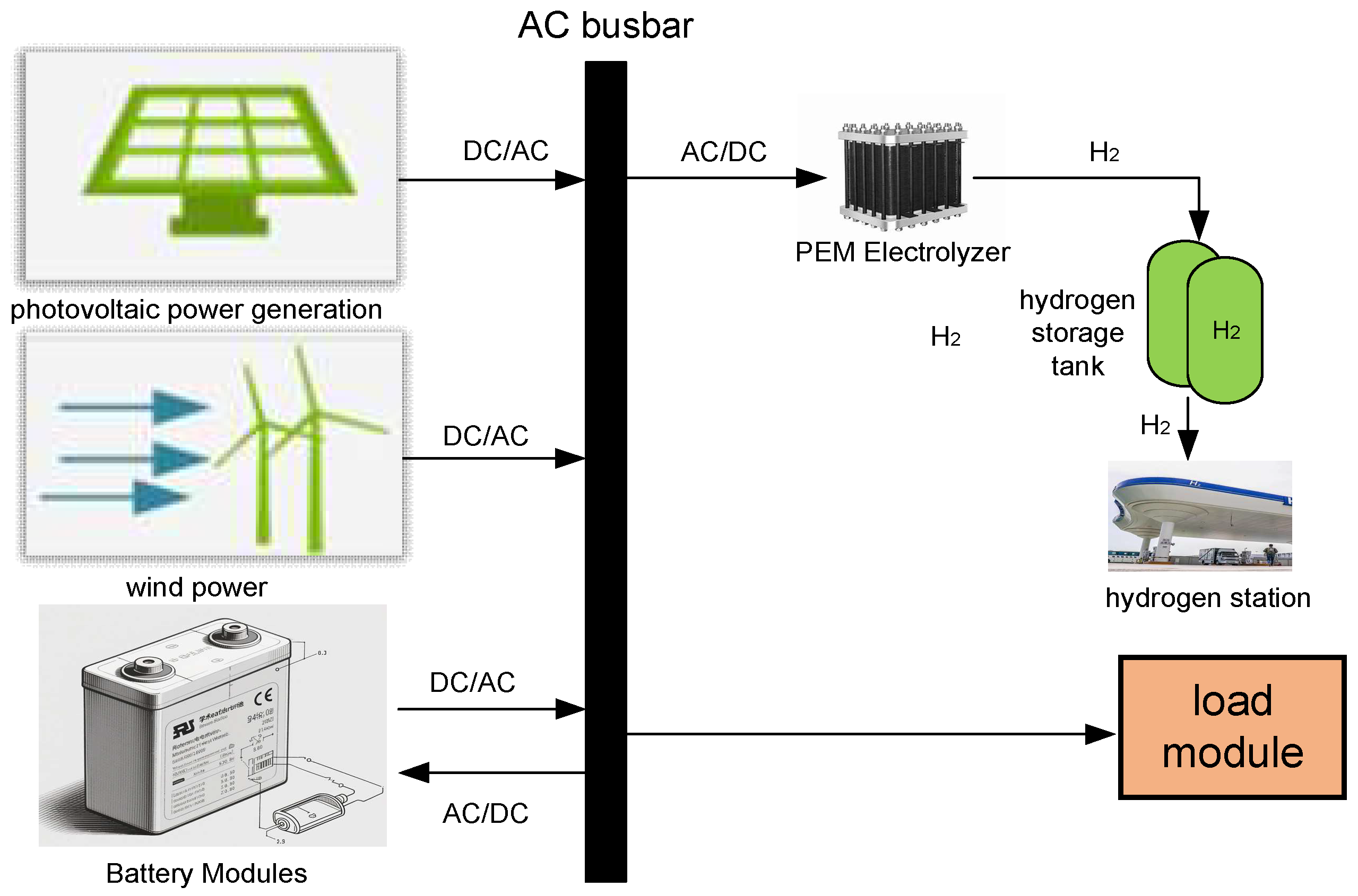
26], in order to improve the dynamic operation flexibility of the wind and light green hydrogen system and the efficiency of the hydrogen production of the microgrid system constructed as shown in
Figure 1.
The wind-solar complementary electrolytic hydrogen production system includes a wind turbine, a photovoltaic array, a battery storage system, and a PEM electrolytic hydrogen production system. Wind power generation utilizes wind turbines to capture wind energy and then convert mechanical energy into electrical energy; photovoltaic power generation utilizes solar panels to convert light energy into electrical energy; and the PEM system converts excess electrical energy into hydrogen by electrolyzing water to produce hydrogen and storing it. Complementary wind and solar power generation system can improve the random instability of power supply of single wind power generation or single photovoltaic power generation to a certain extent, but compared with the controllability and dispatchability of thermal and nuclear power generation resources, wind and solar power generation system is subject to the influence of the natural climate, which is characterized by serious instability, randomness, intermittency and volatility. Combining the electrolytic hydrogen production system with the battery energy storage system can effectively adjust the imbalance between power generation and power supply, cut peaks and fill valleys, smooth power fluctuations, and make wind power and photovoltaic power a controllable and dispatchable green power source, thus ensuring the continuity and stability of wind and solar power generation and realizing a continuous power supply.
A wind power system consists of two components: a wind turbine and a generator. Wind power systems utilize wind turbines to convert wind energy captured by impellers into mechanical energy, which is converted into electrical energy by generators. The power P of a wind turbine is defined as the power of its captured wind energy converted into usable mechanical energy:
where:
R is the diameter of the wind turbine in m;
is the wind speed in
;
is the wind energy utilization coefficient;
is the tip speed ratio;
is the rotational speed in
;
ρ represents the air density.
The curve modeling method includes the function method and the table method [
27]. In this study, the function method is mainly adopted, and the calculation formula is:
where:
is a constant, determined by the wind turbine characteristics;
is the blade pitch angle.
The instability of wind power generation is due to various uncontrollable factors, dominated by wind speed, affecting the energy conversion power of the wind turbine. In order to get the most energy under dynamic, uncontrollable conditions, the development of maximum power point tracking (MPPT) technology for wind turbines is crucial. In this paper, the maximum power point tracking control (MPPT) of a wind turbine is realized by using the variable step size perturbation observation method to improve the economy of the wind power generation system.
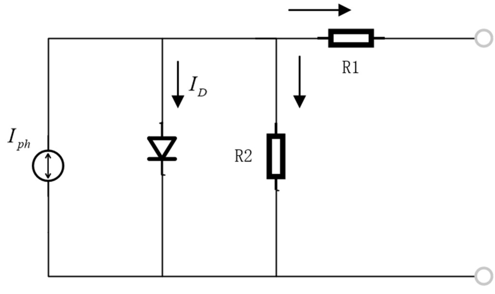
In this paper, the photovoltaic power generation system uses crystalline silicon solar cell array, in which the photovoltaic array consists of a large number of series-parallel photovoltaic modules, and photovoltaic modules and a large number of solar cells, in this paper, the number of photovoltaic modules in series is 10, and the number of parallel is 20. The actual equivalent circuit model of the crystalline silicon photovoltaic cell is shown in
Figure 2, and it can be approximately regarded as a nonlinear diode paralleled with a photogenerated current source. In
Figure 2,
is the total diffusion current of the diode,
is the current of photons excited in the solar cell,
is the series resistance, and
is the equivalent parallel resistance.
According to the operating principle of PV cell, equivalent circuit, and Kirchhoff’s current law, the output characteristic equation of PV cell can be obtained as [
28]:
where
is the open-circuit voltage;
is the photogenerated current, and the short-circuit current
is equal to the photogenerated current;
C1 and
C2 are correction coefficients.
There is at the maximum power point:
where
is the voltage at the maximum power point;
is the current at the maximum power point.
Photovoltaic cells are affected by changes in light intensity and temperature during their operation, so when the external environmental conditions change, the values of the above parameters will also change. Therefore, it is necessary to introduce the light intensity
and temperature
in the standard condition, so that
,
, to get the parameters of the PV cell in the new environment as follows:
In the formula, a is the current temperature coefficient; b is the light intensity-voltage correction coefficient; c is the voltage temperature coefficient; △S is the increment of light intensity change.
Solar power generation is unstable because various uncontrollable factors affect the utilization of solar cells, such as solar irradiance and temperature. The load impedance and output impedance of the solar cell are the main factors affecting the output power of photovoltaic power generation, and adjusting the matching degree of the two can realize the MPPT of the solar cell and improve the economy of the photovoltaic power generation system.
Photovoltaic power generation models use MPPT technology to achieve maximum power output from PV power generation. In a PV power generation system, the PV array consists of multiple PV modules arranged in series and parallel to meet the power needs of different loads. Assuming that the PV array consists of N PV modules connected in series and M modules connected in parallel, the power output model of the PV power generation system is expressed as:
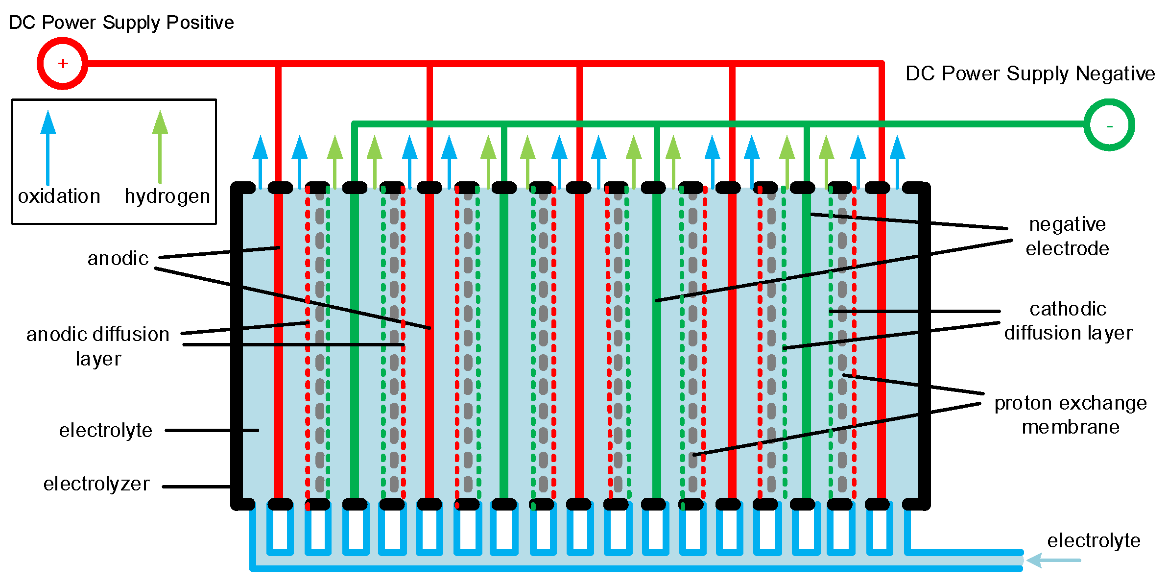
Electrolyzer is an important equipment in the hydrogen production system of electrolyzed water, and its working condition affects the hydrogen production efficiency of the whole system. The basic working principle of the electrolyzer is that it is energized by two electrodes, generating
at the anode and
at the cathode. The structure of the PEM electrolyzer is shown in
Figure 3, and a large electrolyzer is composed of several small chambers, each of which includes a proton exchange membrane, a cathode plate, and an anode plate.
The electrolytic hydrogen production system generates hydrogen by electrolyzing water, and this process is actually a complex process from electrical energy to chemical energy to hydrogen energy, so the mathematical model of the electrolyzer unit mainly consists of an electrical model and an electrochemical analytical model. From the circuit point of view, the electrolyzer unit is a nonlinear DC load, and factors such as input current, operating temperature, and operating pressure all have an effect on the output voltage of the electrolyzer [
29]. The electrical model of hydrogen production from electrolyzed water, i.e., the voltage operating characteristics of the electrolysis hydrogen production system, can be expressed as [
24]:
where
is the working voltage of the electrolyzer in V;
is the reversible voltage of the electrolyzer with temperature change in V;
is the working current of the electrolyzer in A;
is the ohmic resistance parameter of the electrolyte;
is the working temperature of the electrolyzer in °C;
is the parameter of over-voltage on the electrodes of the electrolyzer; and
is the surface area of the electrodes of the electrolyzer in
.
The reversible voltage of the electrolyzer
is related to the temperature of the electrolyzer
by the following equation:
where
is the reversible voltage at standard conditions and
is the empirical temperature coefficient of the reversible voltage.
The hydrogen production rate of the electrolyzer is directly proportional to the input current, and the hydrogen production rate can be controlled by adjusting the input current to realize the dynamic load balance of the system. In the large-scale hydrogen production process a number of single electrolyzer are often needed for series work, composed of n units in series electrolyzer hydrogen production rate is:
where
is the Faraday efficiency factor;
k1,
k2 are constants; and
A is the diaphragm area;
n is the number of electrolytic chambers;
F is the Faraday constant.
The hydrogen storage tank (HST) is an important component of the hydrogen storage system. Its main function is to store the hydrogen produced by the electrolyzer. The device can meet two needs at the same time: one is to directly provide hydrogen for the hydrogen load in the system, and the other is to serve as a hydrogen source for fuel cell power generation. The storage capacity of the hydrogen storage tank changes as follows:
where:
TCP is the compressor inlet temperature, which is equivalent to the ambient temperature;
WCP is the gas flow rate at the compressor outlet;
ηCP is the compressor working efficiency;
CP_H2 is the specific heat capacity of hydrogen, which is 14.233 kJ/kg·K;
P1 and
P2 are the compressor inlet pressure and outlet pressure;
κ is the specific heat capacity, which is 1.4.
3. Modeling of Control Strategies for Virtual Synchronous Machines
3.1. Virtual Synchronous Generator Model Analysis
In order to improve the grid connection characteristics of new energy power generation systems through the converter, scholars at home and abroad have proposed the VSG technology, which makes the converter have inertia, damping, and frequency and voltage regulation characteristics through the control algorithms, and then improves the system grid connectivity.
VSG control has been widely used in conventional power generation systems, and its technology is now very mature and mathematically modeled under various operating conditions. From the point of view of physical structure, VSG is composed of rotor and stator, and from the point of view of mathematical model, it is composed of mechanical and electrical parts. Mechanical part of the VSG rotor equation of motion to represent the electrical part of the stator voltage equation, if you ignore the VSG iron loss, copper loss and other related losses, then the VSG rotor mechanical equations such as the relationship between the formula:
where
J is the moment of inertia;
is the electrical angular velocity;
is the mechanical and electromagnetic power of the VSG;
is the mechanical and electromagnetic torque of the VSG, respectively.
The VSG electromagnetic torque expression is given in the following equation:
In the formula, if is the excitation current; i0 is the virtual magnetic flux; cos(θ − θi) is the angle difference cosine term.
Considering the damping characteristics of the VSG, the expression of the rotor mechanical equation of the VSG is changed to:
where
is the rated angular velocity of the VSG;
is the actual angular velocity of the VSG; and
D is the damping coefficient of the VSG.
The stator excitation winding of the VSG can be considered as a centralized winding with self-inductance
. The mutual inductance between the excitation winding and the stator winding varies with the electrical angle
of the rotor and can be expressed as the following equation:
Among them,
,
and
are the mutual inductance of the stator and rotor windings of the rotor shaft, and
is the amplitude of the stator and rotor mutual inductance. Then the magnetic chain of each winding of VSG
and the current on each winding
are organized as follows:
If the VSG does not contain a neutral, then there is the expression:
Combining Equation (22) we obtain the stator magnetic chain expression as:
The rotor magnetic chain expression is:
where
denotes the dot product operation. When the three-phase currents are sinusoidal and symmetrical, the second term in Equation (23) is constant. Therefore, assuming that the resistance of the stator winding is
and the terminal voltage
is the terminal voltage of each phase winding of the VSG, the equation for the stator terminal voltage of the VSG is given in the following equation:
where
is the counter electromotive force generated when the rotor rotates. The electromotive force e and the electrical angle
θ of the rotor are introduced into the voltage-current double closed-loop loop junction to generate the pulse signal that triggers the inverter.
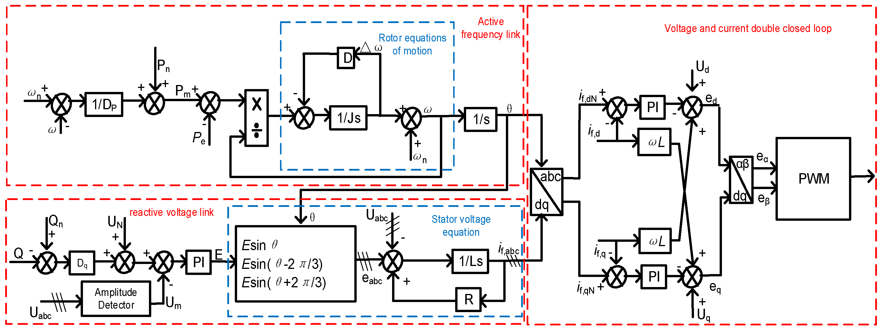
The specific VSG control strategy is shown in
Figure 4. The VSG control strategy basically consists of three parts: the active frequency link, the reactive voltage link and the voltage-current double-closed loop, in which the active frequency link generates the rotor’s electrical angle
θ, the reactive voltage link generates the electromotive force e, and then the voltage-current double-closed loop link generates the corresponding PWM signals according to the generated rotor’s electrical angle
θ and electromotive force e, controlling the inverter’s Then the voltage-current double closed-loop link generates the corresponding PWM signal according to the generated rotor angle
θ and electromotive force e to control the inverter’s on-off.
3.2. Virtual Synchronous Motor Model Analysis
The basic idea of VSM is to build a transient model using the rotor motion and stator electrical equations of a synchronous motor, and then introduce this model into the controller in order to equip the inverter with the operating characteristics of a synchronous motor. A fully controlled rectifier under a VSM control strategy is used to realize the frequency regulation.
The VSM second-order model includes stator electrical equations and rotor equations of motion. Where the stator electrical expression is shown below:
where:
is the stator electromotive force;
is the stator terminal voltage;
is the stator current;
L′ is the filter inductance;
is the stator resistance;
is the synchronizing reactant.
The equations of motion of the rotor can be obtained from the mechanical equations, the expression of which is shown below:
where:
J is the rotational inertia of the virtual synchronous rectifier;
is the virtual proposed electromagnetic torque;
is the virtual mechanical torque;
D is the damping coefficient;
ω0 is the mechanical angular frequency of the virtual synchronous rectifier;
ωs is the rated angular frequency.
The electromagnetic torque
can be calculated from the measured input voltage and current values as shown in the following expression:
where:
PE is the input power of the IGBT three-phase rectifier circuit.
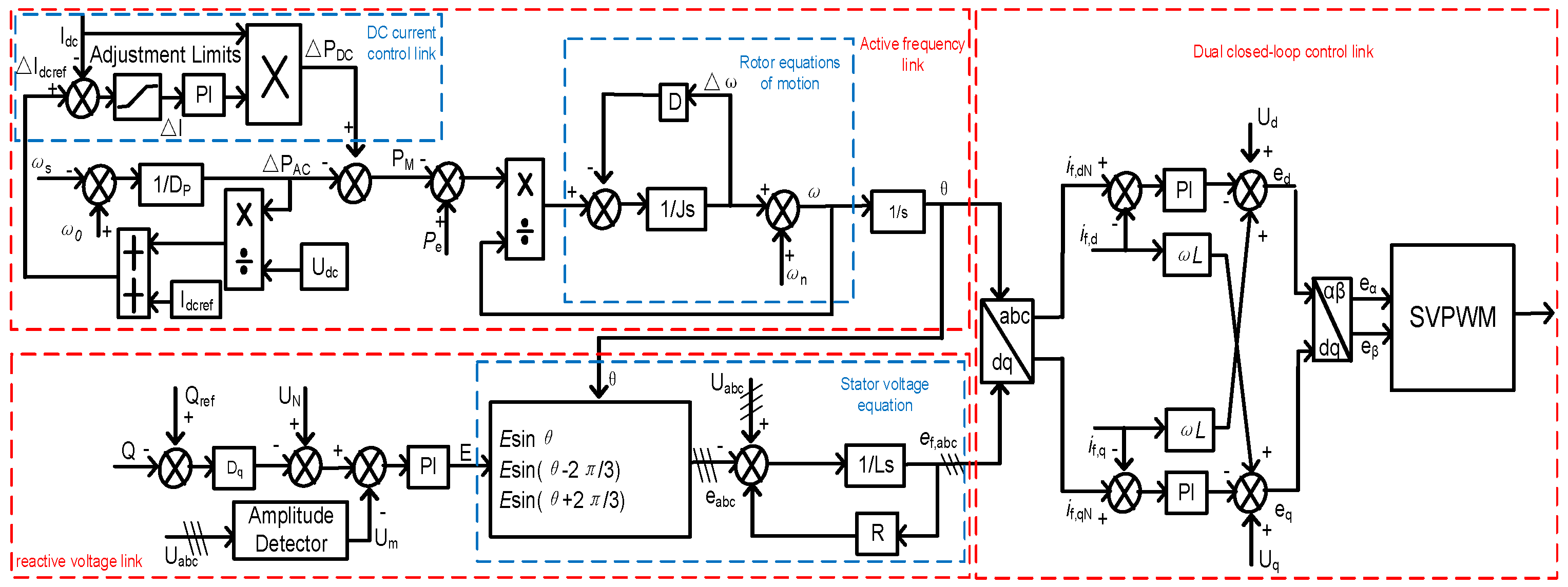
The overall control strategy framework of the VSM consists of four main parts: the active power and frequency link, the reactive power and voltage link, and the double closed-loop control link, as shown in
Figure 5. The active power and frequency link is further subdivided into the DC current control link and the rotor motion equation. In the DC current control link, the frequency deviation of the system is converted and subtracted from the preset current value, so as to stabilize the DC side current; moreover, the introduction of the speed limitation can effectively avoid the phenomenon of sudden current change. The reactive power and voltage link includes the stator voltage equation link to generate the required potential e
f,abc.
Comparing the VSG control strategy with the VSM control strategy, it can be found that in the active frequency link, when calculating the mechanical power, the power calculations of VSG and VSM are opposite; in addition to that, when calculating the stator voltage, the signs are equally reversed.
3.3. Overall Coordinated Control Strategy
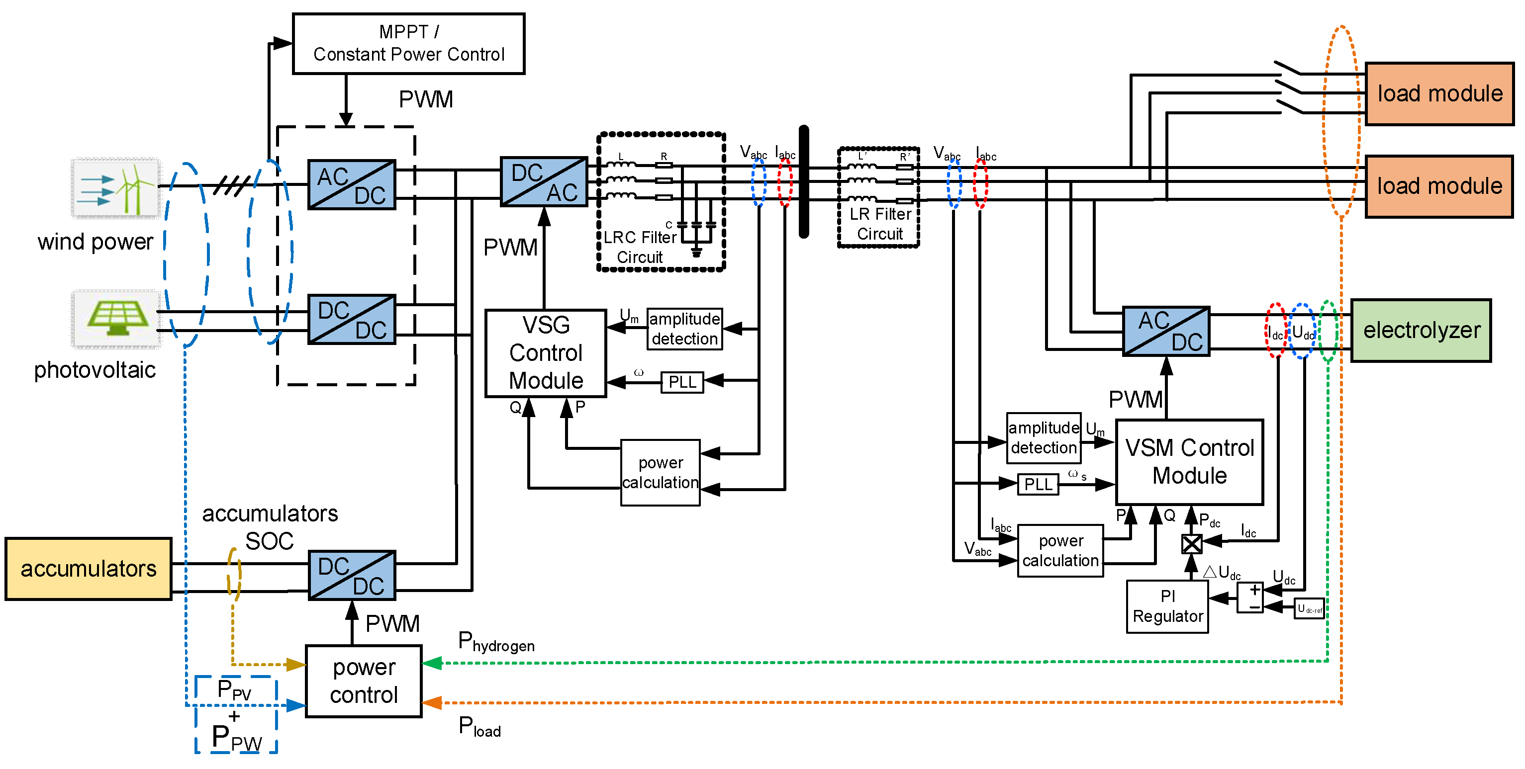
The overall control structure of the wind-solar hybrid hydrogen production system based on the coordinated control of VSG and VSM is shown in
Figure 6. In this system, each unit is brought together in the AC bus through the converter, which realizes the cooperative operation of multiple energy sources and the effective control of the hydrogen production system. Among them, the grid-side converter adopts VSG control, so that the system has inertia and primary FM response characteristics to realize friendly grid connection; the hydrogen production system adopts the VSM-controlled rectifier to connect to the AC bus as a DC load or DC-side energy storage device. There is a close synergistic relationship between the electrolyzer and the battery, on the one hand, they work together as the energy and power support for the inertia and primary FM response of the VSG, and play a key role in maintaining the stability of the AC bus voltage in the process of absorbing/compensating for the unbalanced power of the system; on the other hand, considering that there is a safety risk for the electrolyzer when the operating power is lower, the battery supplies power to the electrolyzer when necessary, in order to avoid the electrolyzer frequent starting and stopping. On the other hand, considering the safety risk of the electrolyzer in low power operation, to avoid frequent starting and stopping of the electrolyzer, the battery supplies power to the electrolyzer when necessary.
In order to keep the capacity of the battery in a safe range from 10% to 90%, the hydrogen system is complementarily adjusted through the hydrogen system. When the capacity of the battery system is more than 90%, the power load of the hydrogen system is dynamically adjusted to further reduce the consumption of wind power and slow down the charging speed of the battery system to avoid overcharging; when the capacity of the battery system is less than 10%, the power load of the hydrogen system is dynamically adjusted to further reduce the load consumption and slow down the discharging speed of the battery system to avoid overdischarging. When the capacity of the battery system is lower than 10%, the power load of the hydrogen production system is dynamically adjusted to further reduce the load consumption and slow down the discharge speed of the battery system to avoid the occurrence of the over-discharge phenomenon.
In this system, the battery system uses a power control strategy that combines the wind power, the hydrogen production system power, and the residential load to achieve stable operation and power balance. The power balance relationship can be expressed as:
where
PBatter is the battery output power;
PPV is the photovoltaic power;
PPW wind power;
Pload is the residential load power, and
is the power consumed by the hydrogen production system.
The power control automatically adjusts the output power of the battery according to the change of the electrical quantity of the system, and the battery is charged and discharged accordingly when the power of wind power generation changes with the demand of the residents’ load. When the wind and light power are sufficient to exceed the residential load, the excess power is used to charge the battery, increasing its output power; on the contrary, when the discharge is required to supplement the power shortage, the output power decreases. The relationship between battery output power and bus voltage can be expressed as:
where
P*
Batter is the rated power of the battery, k
v is the voltage sag factor,
V is the actual voltage of the bus, and
V* is the rated voltage of the bus.
Batteries and the hydrogen production system cooperate with each other, and the working status of the hydrogen production system affects the power output of the batteries. When there is excess wind and light, the power of the hydrogen production system can be increased to reduce the pressure of battery charging; when there is insufficient wind and light and the battery power is low, the power of the hydrogen production system can be appropriately reduced to slow down the discharge rate. At the same time, the power control can maintain DC bus voltage stability, determine the slope of output power change based on electrical quantities by setting the sag coefficient, achieve coordinated operation with other components, and enhance resource utilization efficiency and load adaptability.
In order to ensure the safe operation and service life of the battery, it is necessary to consider its state of charge (SOC). When the SOC is too high or too low, it is necessary to take measures such as adjusting the sag coefficient and limiting the charging and discharging power to prevent overcharging or overdischarging. Practical applications also need to consider the line impedance, the power limitations of each part of the power control strategy to optimize and adjust, in order to achieve accurate and reliable power control.
4. Simulation Example
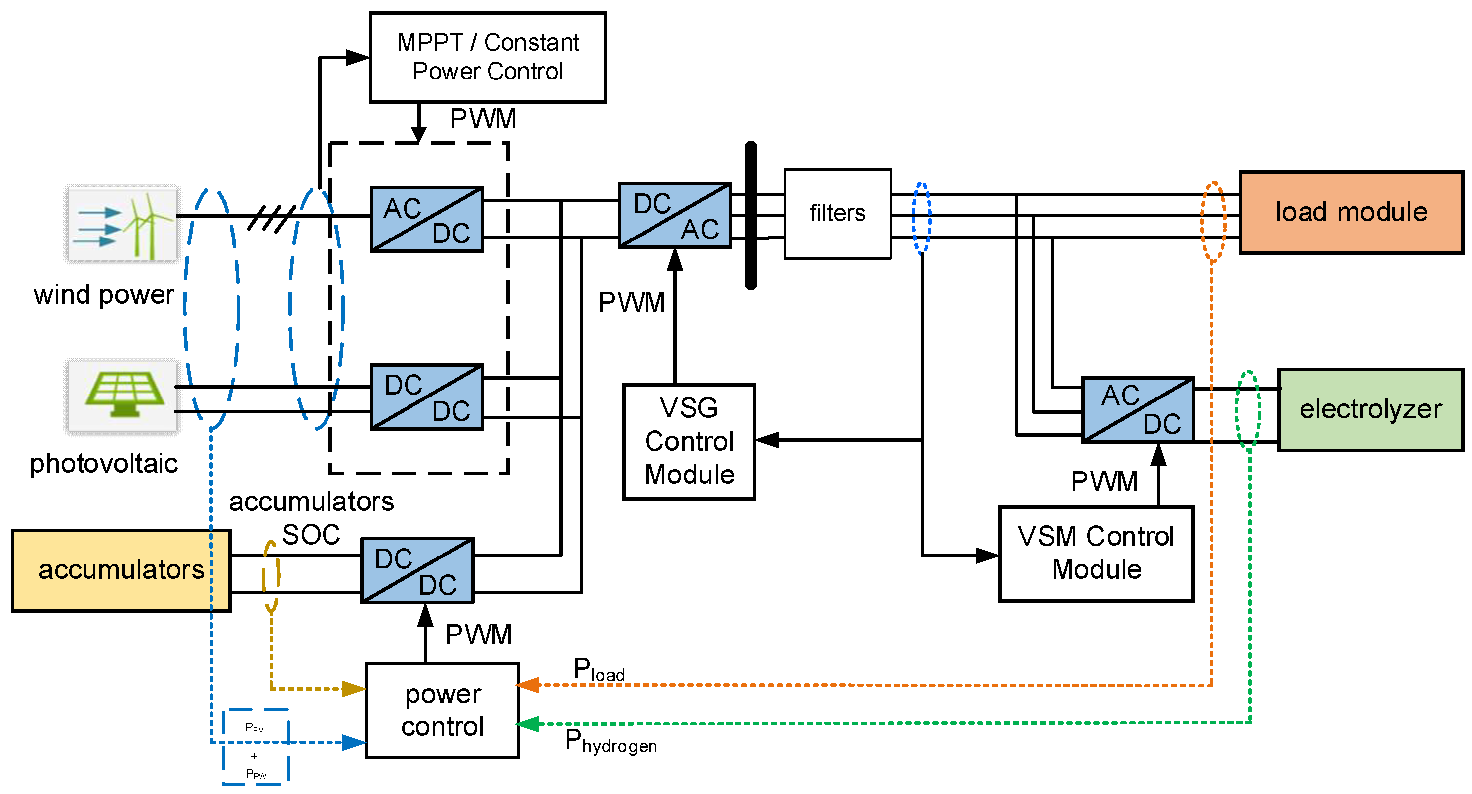
In order to test the effectiveness and advantages of the wind-solar complementary hydrogen production system based on the coordinated control of VSG and VSM proposed in this paper, the wind-solar complementary hydrogen production system shown in
Figure 7 is constructed using MATLAB/simulink, which consists of photovoltaic (PV), wind turbine (wind turbine), storage battery, VSG control module, VSM control module, hydrogen production system, and load module. Among them, the photovoltaic module and wind turbine module are used as power generation units, the battery is used for energy storage and power regulation, the VSG control module realizes the grid-connected control, the VSM module is used for rectification, the hydrogen production system exists as a long-time energy storage unit, and the load module is used to simulate the load variation.
The parameter settings in the above circuit are shown in
Table 1. The initial parameters of the system are the initial power of the PV is 30 kW, the initial power of the wind power is 23 kW, the power of the hydrogen production system is 20 kW, and the initial load of the load module is 20 kW.
Building the above model, the wind-solar hybrid hydrogen production system, under the premise of meeting the above initial conditions, verifies the different responses of the system under three working conditions, which are shown in
Table 2.
4.1. Load Change Experiment
According to
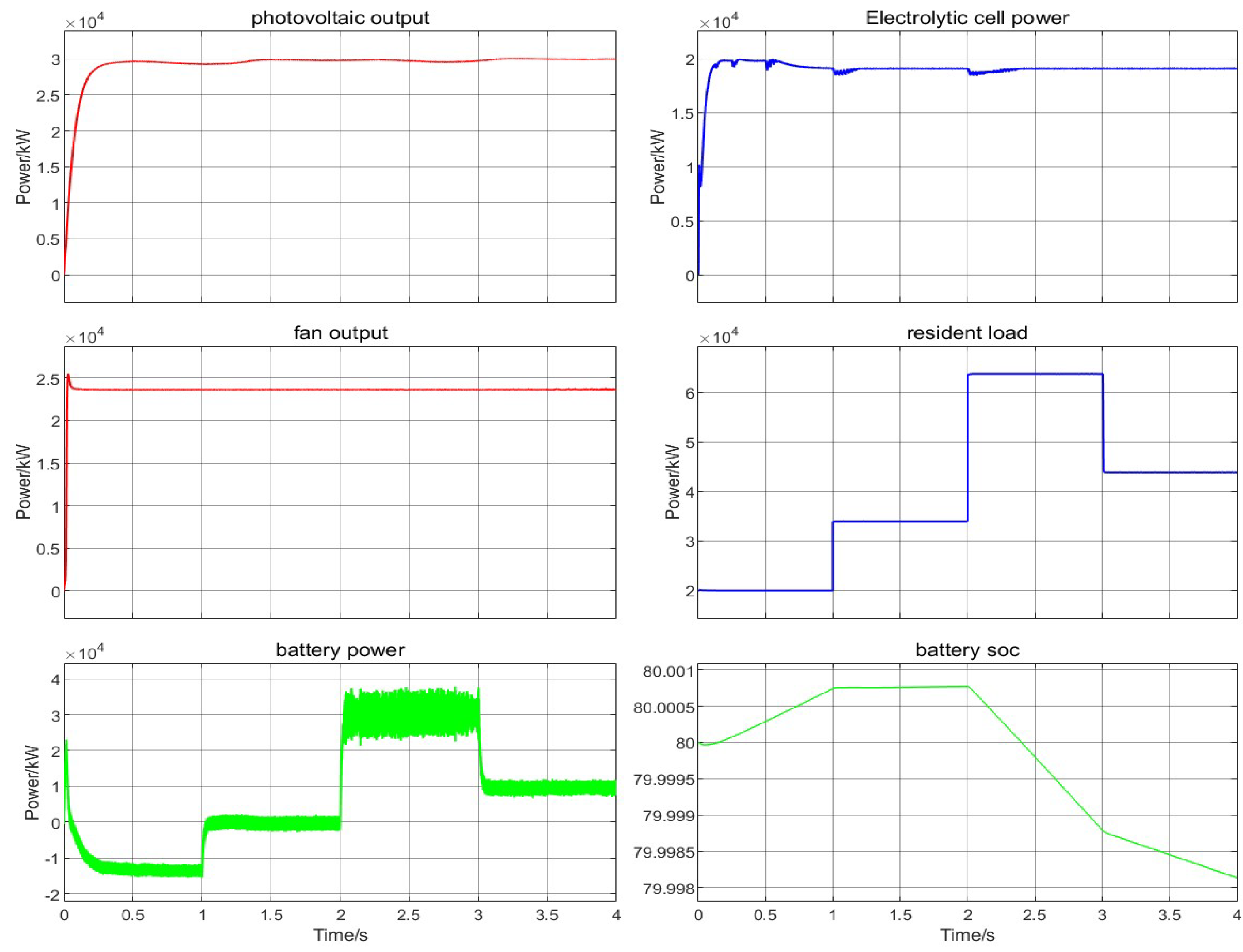
Table 2, the experiment of working condition 1 is carried out under the precondition that the wind-solar hybrid hydrogen production system satisfies the initial conditions, which are as follows: the initial conditions are 30 kW of PV output, 23 kW of wind turbine output, and 20 kW of hydrogen production load, and the initial load is 20 kW. The change of the load side occurs, and the load is put into 13 kW at 1 s, and the load is put into 30 kW at 2 s, and the load is cut out at 3 s. 20 kW of load. The specific simulation is shown in
Figure 8 and
Figure 9.
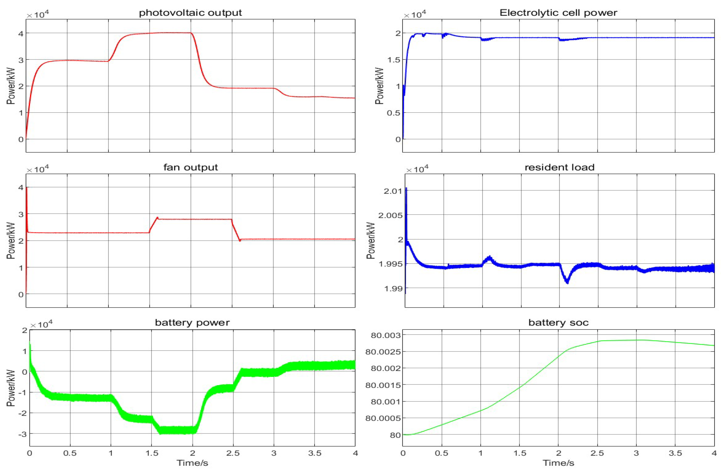
As shown in
Figure 8, the system’s PV and fan outputs are stable and remain around 30 kW and 23 kW, respectively, providing the system with a basic source of electrical energy. When the load power is put into the 13 kW load at 1 s, and then put into the 30 kW load at 2 s, and cut out the 20 kW load at 3 s, the hydrogen production system can be quickly adjusted to maintain stable hydrogen production, and the battery power is adjusted accordingly, and the battery presents a charging state when the system output is greater than the load consumption, such as the initial state of the system from the interval of 0 s to 1 s; after putting in the 10 kW load at 1 s, the After putting 10 kW load at 1 s, the system power and load reach a balance, at this time, the battery is in a silent non-charging state; When putting 30 kW load at 2 s, the system power is lacking, and the battery is treated as a power source; when cutting out 20 kW load at 3 s, the system power overflows, and the battery starts to be charged. In this process, the battery SOC also changes accordingly, which visualizes the energy storage state of the battery.
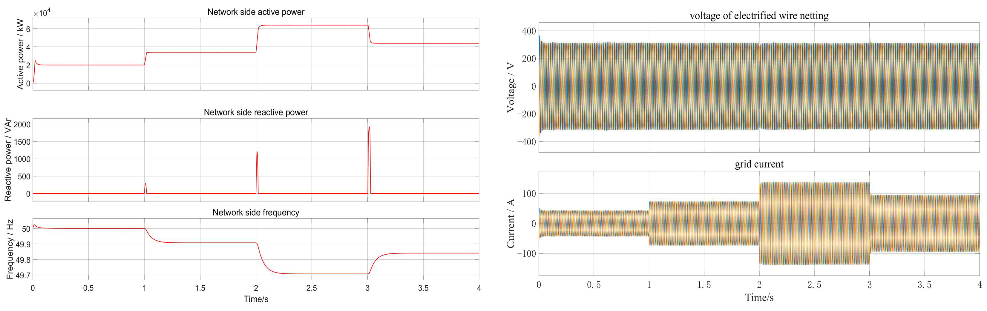
As shown in
Figure 9, during the dynamic change of load, the system presents multi-level response characteristics: active power is regulated in milliseconds through a fast tracking mechanism and its change rate is strongly coupled with the frequency fluctuation rate—when the frequency change rate caused by the sudden load change exceeds the ±0.5 Hz/s threshold, the electrolytic power is reversely compensated with a gradient of 2.5 MW/s through a dynamic decoupling algorithm. This mechanism effectively limits the frequency fluctuation amplitude to the range of 49.7–49.8 Hz; reactive power generates a 200 kVar transient pulse when the load is impacted, but the zero line is restored within 40 ms with the help of a coordinated control strategy; although the voltage and current on the grid are disturbed, they still maintain a high-quality waveform with THD < 3%. The system achieves an adaptive balance between stable power supply and load fluctuations under the frequency-electrolysis power collaborative control framework through dynamic adjustment of battery SOC and instantaneous power buffering of supercapacitors, ultimately achieving high-quality dynamic performance with voltage deviation ≤ 2.5% and frequency recovery time < 0.3 s, verifying the effectiveness of collaborative control of the multi-energy complementary system.
Under working condition 1, the system generating power is stabilized to supply energy for the system, and the power of each part of the system is adjusted accordingly when the load power changes dynamically; the battery is reasonably charged and discharged, and the SOC changes accordingly. The active, reactive power, and frequency can adapt to the load change to realize power balance, and the voltage and current control of the grid side are stable, which indicates that the system can effectively cope with the load change under this working condition, and the various parts work well together.
4.2. Source-Side Variation Experiments
According to
Table 2, under the precondition that the wind-solar hybrid hydrogen generation system meets the initial conditions, the experiment of working condition 2 is carried out, and the specific working condition is as follows: the initial conditions are kept unchanged, and the source-side output is changed, when the time-voltage output is increased to 40 kW in 1 s, the wind turbine output is increased to 28 kW in 1.5 s, the time-voltage output is reduced to 19 kW in 2 s, the wind turbine output is reduced to 20 kW in 2.5 s, and the time-voltage output is reduced to 15 kW in 3 s. The simulation is shown in
Figure 10 and
Figure 11.
As shown in
Figure 10, at this time, the fan and PV power generation of the system has obvious dynamic changes, 1 s when the photovoltaic power increases to 40 kW, 1.5 s when the fan power increases to 28 kW, and then the PV and fan power gradually decreases, 2 s when the photovoltaic power decreases to 19 kW, 2.5 s when the fan power decreases to 20 kW, and 3 s when the photovoltaic power decreases to 15 kW. This power generation fluctuation puts higher requirements on the energy management of the system. The load power remains unchanged at 20 kW, which contrasts with the dynamic change of power generation and requires the system to reasonably adjust the energy distribution to maintain the power balance. At this time, the hydrogen production system keeps 20 kW power unchanged, and the battery power is regulated by charging and discharging according to the difference between the generation power and the load power. In 1 s, the photovoltaic power increases, the system power overflow, the battery charging power increases; in 2.5 s~3 s, the system power and load balance is reached, the battery charging power is unchanged; in 3 s, the photovoltaic power decreases, the photovoltaic and wind power is insufficient, the battery discharging power increases to maintain the system balance. In this process, the battery SOC also changes accordingly, reflecting the energy storage state of the battery.
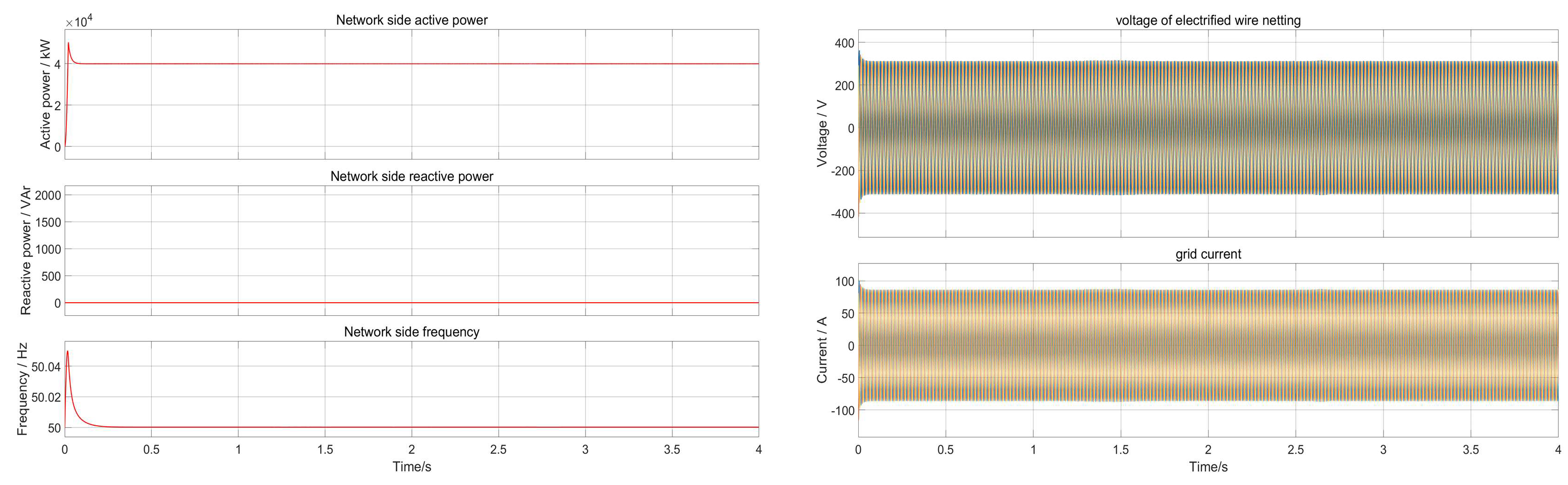
As shown in
Figure 11, in the dynamic process of working condition 1, the system achieves energy balance and bus stability through multi-module collaborative control: the photovoltaic output quickly rises to 40 kW within 1 s, and then gradually decays to 15 kW at 3 s; the wind turbine output reaches a peak of 28 kW at 1.5 s and then falls back to 20 kW. The fluctuations of the two form a significant power generation gap. The battery, as the core regulation unit, absorbs excess energy with +18 kW charging power during the photovoltaic output surge stage at 1s, and switches to −24 kW discharge mode to maintain power supply when power generation is insufficient at 3s, accurately matching the power generation-load difference. On the AC bus side, despite the drastic fluctuations at the power supply end, after being controlled by the virtual synchronous machine, the active/reactive power is always stable at 20 kW/0 kVar, the frequency is constant at 50 Hz, the voltage is maintained at 400 V, and the current waveform is not distorted (THD < 3%). This verifies that the system can still achieve zero bus parameter through millisecond-level power bidirectional switching of the battery and VSG inertial support under the large fluctuations of wind and solar output.
Under operating condition 2, the power generation of the system shows obvious dynamic changes, while the load power remains unchanged, which places higher requirements on energy management. The system rationally allocates energy to maintain power balance through battery charging/discharging regulation based on the difference between generation and load power and the corresponding SOC changes. Meanwhile, despite the fluctuation of power generation, the active and reactive power, frequency, voltage and current of the AC bus of the system can be stabilized through the VSG control strategy, which indicates that the system can effectively cope with the change of power generation and ensure the stable operation of the system under this working condition.
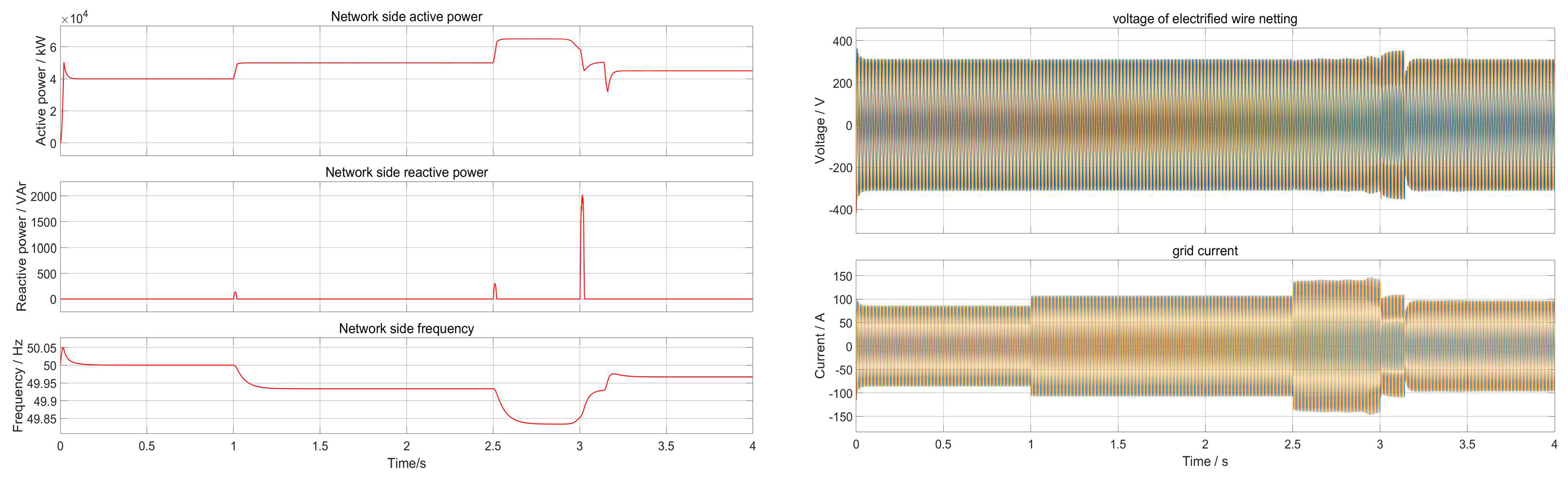
4.3. Experiment on Simultaneous Change of Power Supply and Load
According to
Table 2, under the precondition that the wind-solar hybrid hydrogen generation system meets the initial conditions, the experiment of working condition 3 is carried out, which is as follows: the initial conditions are kept unchanged, and the source-side output and load-side load are changed at the same time. The time-voltage output is increased to 40 kW and put into the load of 10 kW in 1 s, the wind turbine output is increased to 28 kW in 1.5 s, the time-voltage output is decreased to 19 kW in 2 s, the time-voltage output is decreased to 20 kW and put into the load of 15 kW in 3 s and cut off the load of 20 kW in 2.5 s the turbine output decreases to 20 kW and puts in 15 kW load, 3S the time-voltage output decreases to 15 kW and cuts out 20 kW load. The specific simulations are shown in
Figure 12 and
Figure 13.
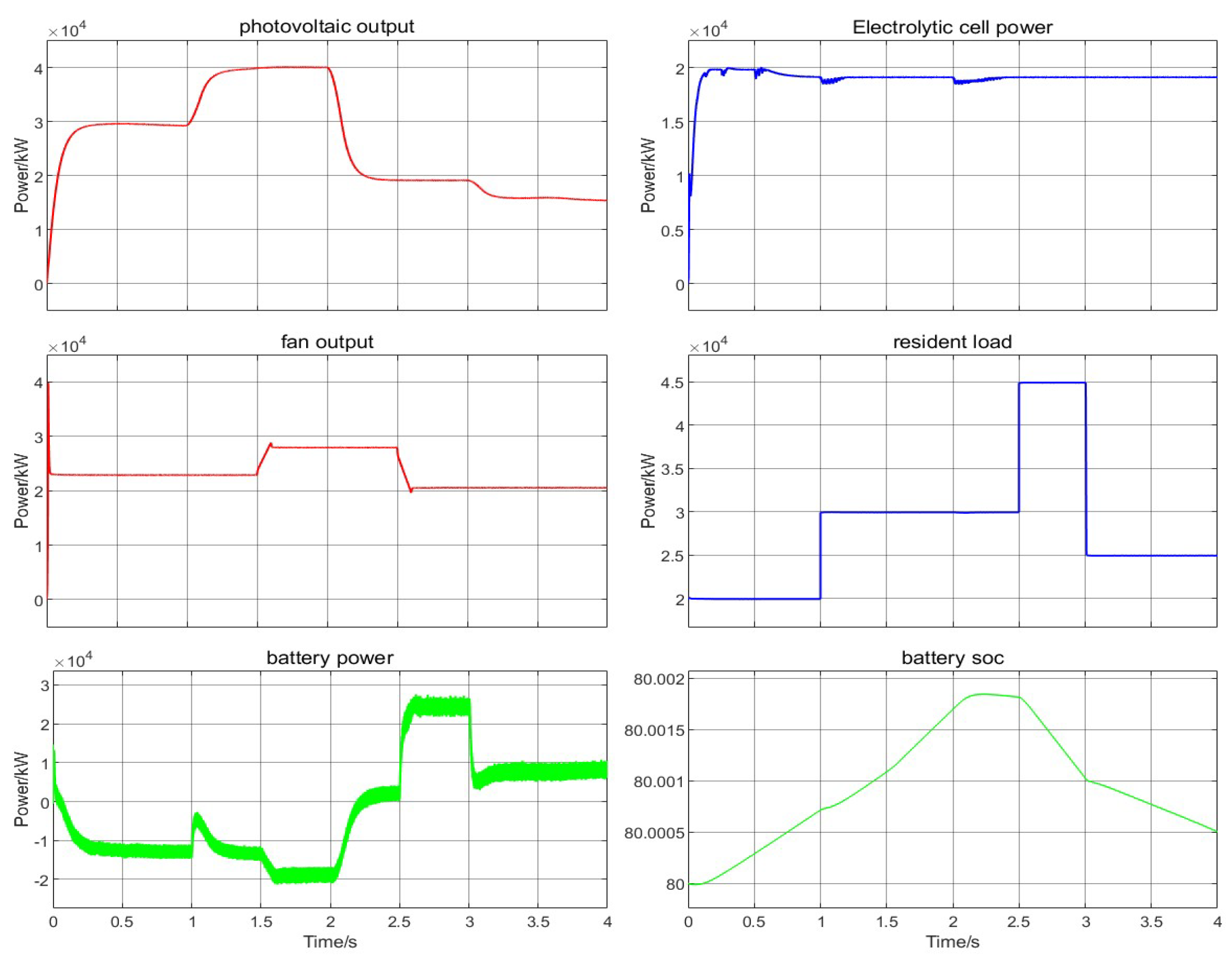
As shown in
Figure 12, at this time, the wind turbine and PV power changes are similar to Case 2, with the photovoltaic power increasing to 40 kW in 1 s, the wind turbine power increasing to 28 kW in 1.5 s, and then gradually decreasing, and the photovoltaic power decreasing to 15 kW in 3 s. The load power changes are more complex compared to Case 1, with the load increasing by 10 kW in 1 s, then increasing by 15 kW in 2.5 s, and then cutting out the 20 kW load in 3 s. The load power changes are more complicated than in Case 1. This puts the system’s power balancing capability to a more severe test. Under this condition, the hydrogen production system still considers stabilizing 20 kW power for stable operation. The battery power is finely adjusted according to the complex changes of power generation and load power. When the generation power is greater than the load, the battery absorbs the excess power; when the generation power is less than the load, the battery participates in the system operation as a power source to make up for the insufficient power of photovoltaic and wind power. In this process, the SOC of the battery changes accordingly, which visualizes the energy storage status of the battery.
As shown in
Figure 13, under the condition of severe fluctuations on both sides of the source and load, the system achieves frequency stability and electrolysis power balance through a dynamic correlation mechanism: when the photovoltaic output suddenly increases by 40 kW and a 10 kW load is put into use in 1 s, the instantaneous frequency change rate reaches +0.25 Hz/s, triggering the VSG control unit to synchronously increase the electrolysis power regulation rate, and suppress the frequency increase through the power-frequency coupling effect; when a 15 kW load is added in 2.5 s, the frequency drop rate triggers a −0.18 Hz/s transient offset, and the electrolysis power regulation rate is reversely accelerated to −7 kW/s, forming a dynamic following relationship of “frequency change rate-electrolysis power gradient”. In this process, the VSM algorithm keeps the frequency deviation within ±0.15 Hz by real-time tracking of the frequency deviation value and the power deviation value, and the electrolysis power fluctuation rate is attenuated to a steady-state ±1 kW/s. Although the bus voltage and current experienced three load steps, they still maintained high-quality output of THD < 3% and voltage deviation < 2%, verifying that under the conditions of drastic fluctuations in wind and solar power output and multi-level load jumps, the VSG-VSM collaborative control achieved adaptive stability of multiple objective parameters through the strong correlation response between the frequency change rate and the electrolysis power regulation rate.
Under working condition 3, the generation power and load power of the system change at the same time, which makes the simulation environment more complex, but also closer to the actual situation, so it is a severe test for power balance. The system is finely adjusted by the battery according to the complex changes of the generation and load power, along with the dynamic changes of the SOC, to maintain the power balance. Active power, reactive power, frequency, voltage, and current can adapt to the changes, reflecting the effectiveness of the coordinated control strategy of VSG and VSM and the good control performance of the system, which shows that the system can effectively cope with the complex changes and ensure stable operation under such working conditions.
5. Conclusions
Aiming at the system inertia deficit and power balance problems caused by a high proportion of renewable energy grid-connected, this paper proposes a coordinated control framework based on the two-way interaction mechanism of virtual synchronous machine (VSM). By constructing a synergistic paradigm of dynamic inertia compensation of VSG and flexible load regulation of VSM, a complementary scheduling model of energy storage-hydrogen production under the constraints of battery SOC is established to form a multi-dimensional dynamic matching mechanism of ‘source-load-storage’. Through simulation experiments and multi-working condition verification, the system performs significantly in dynamic power balance, voltage fluctuation range, and wind resource consumption ability, and the main conclusions are as follows:
(1) Based on the VSG/VSM cooperative control strategy, the system’s frequency fluctuation range is stabilized within ±0.15 Hz under sudden load change, source-network fluctuation and source-load synchronization change conditions, which is 62% smaller than that of the traditional sag control strategy, and the voltage deviation is less than 2%. By introducing the virtual inertia dynamic compensation algorithm, the system frequency response time is shortened to 0.3 s, which reaches the equivalent inertia support level of a synchronous generator, and verifies the effectiveness of the multi-timescale power balance mechanism.
(2) After establishing a real-time optimization model considering SOC safety constraints, the complementary scheduling of the battery and hydrogen production system improves the efficiency of wind resource consumption by 28.6%. The battery SOC is always maintained in the safety zone of 15–85%, which improves the charging and discharging cycle life by 40%, and the dynamic adjustment range of hydrogen production power is extended to 10–95%, successfully avoiding the risk of low-power operation of the electrolyzer. Under ±40% fluctuation of wind power, the combined energy storage-hydrogen production system can dynamically adjust the 35 kW power difference, showing strong adaptability to working conditions.
(3) Through the flexible adjustment of the hydrogen production load and the fast response of the storage battery, the system realizes a hydrogen conversion efficiency of 65.2% when the wind power is in excess, and the proportion of redundant power consumption is 42% higher than that of the traditional scheme. Meanwhile, the power balance error of the AC bus is controlled within ±1.5 kW, which verifies the adaptability of the control strategy to complex working conditions.
In summary, this paper effectively solves the stability problem of high-proportion renewable energy grid connection through multi-energy coordinated control and flexible load dynamic adjustment, and at the same time realizes efficient preparation of green hydrogen and optimized operation of the energy storage system. Subsequent research can further combine artificial intelligence algorithms to optimize multi-time-scale control parameters. At the same time, the design of hardware-in-the-loop simulation can be carried out to enhance the practical engineering value of this research. It is also possible to explore the fault ride-through capability of the wind-solar hydrogen storage system in island mode to adapt to more complex practical application scenarios.


