3.1. Material Removal Mechanisms
This section first presents the STEM and EDX analysis results. Subsequently, the results of the different samples are compared with each other. The comparison is used to derive findings on the material removal mechanisms when grinding polycrystalline diamond with a water-based cooling lubricant.
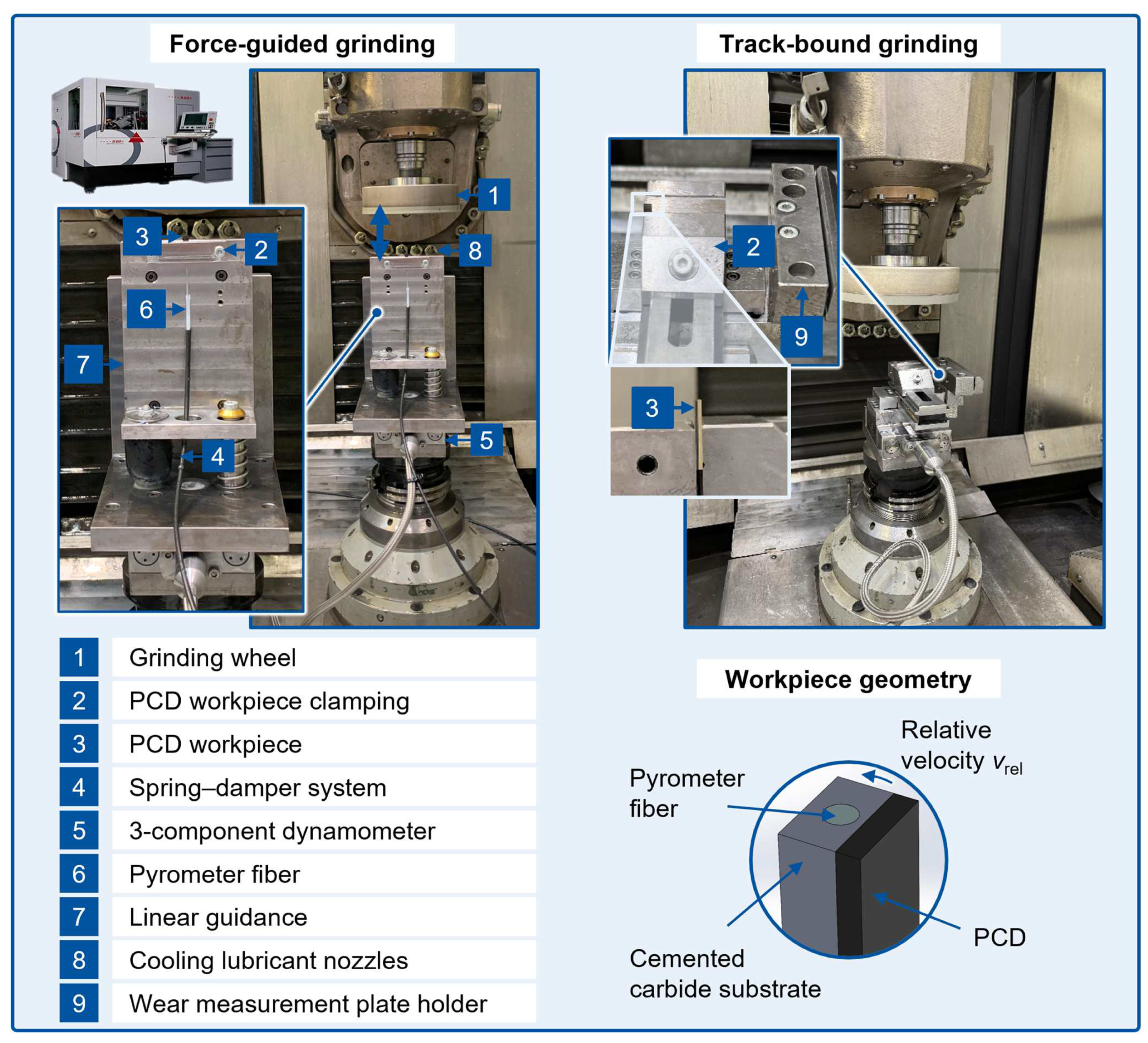
Multiple samples ground with varying process parameters were chosen for the TEM analysis on the effects of the PCD grinding process with a water-based cooling lubricant. STEM images from three samples are presented in
Section 3. One of them was in the initial state before the grinding process. The other two were subjected to a different thermo-mechanical loads during the grinding process. Both presented samples were ground at a cooling lubricant concentration of
xcl = 3% since the cooling lubricant concentration proved to have a decisively lower impact on the resulting thermo-mechanical load to the workpiece than the normal force
Fn and relative velocity
vrel, which was confirmed through the tangential force and temperature measurements in the experiments. The first of the ground samples was machined at a normal force of
Fn = 30 N and a relative velocity of
vrel = 15 m/s (representing experiments with a lower thermo-mechanical load). The second ground sample was machined at a normal force of
Fn = 50 N and a relative velocity of
vrel = 25 m/s (representing experiments with a higher thermo-mechanical load). The experimental results presented in this study, including the EDX analyses, were compiled to representatively illustrate the overall results for the complete research data collected in the context of the work.
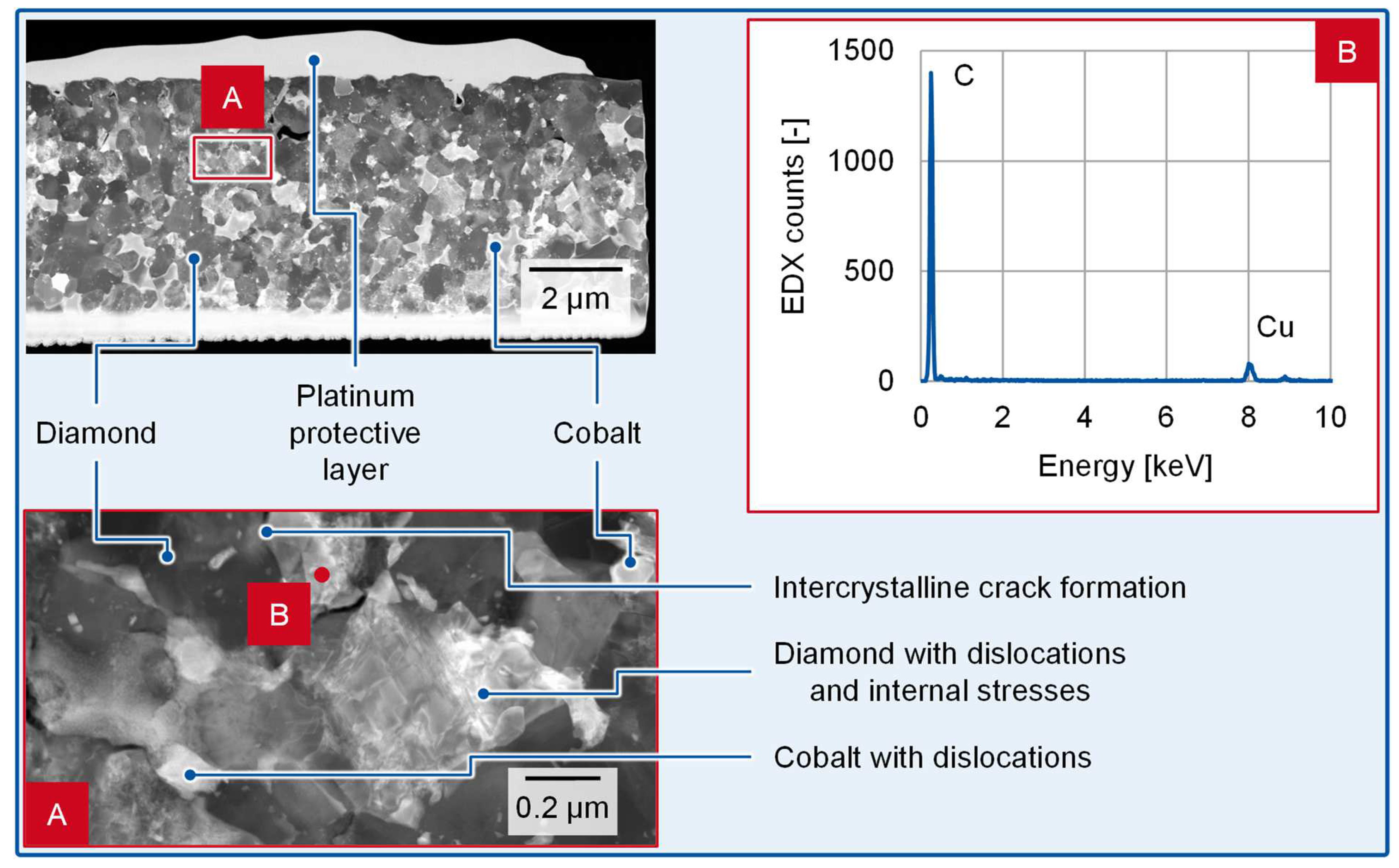
Before investigating the samples prepared in the grinding tests, a reference sample of the same PCD specification was analyzed. This was in order to identify any anomalies in the initial state of the samples. The analysis relied on STEM-DF images, as they allowed for a clearer identification of stresses, dislocations, and cracks in the crystal structure. Therefore, in
Figure 3, dark areas are to be interpreted as diamond grains, while the cobalt share of the material appears as brighter areas.
The general sample microstructure consisted of diamond grains of the expected average diamond grain size
dg ≤ 1 µm, which were in an irregular orientation and interlinked at their contact points. In the spaces in between the diamond grains, residues from the cobalt catalyst were agglomerated.
Figure 3A displays a detail of the DF-STEM image as marked in the overview image. It can be seen that intercrystalline crack formation was already present in the material before the grinding process. Furthermore, the diamond as well as the cobalt crystals already carried dislocations and, partially, signs of internal stresses. In areas where the grayscale in the image did not allow for an unequivocal identification of the present phase, an EDX point analysis was performed, as shown in
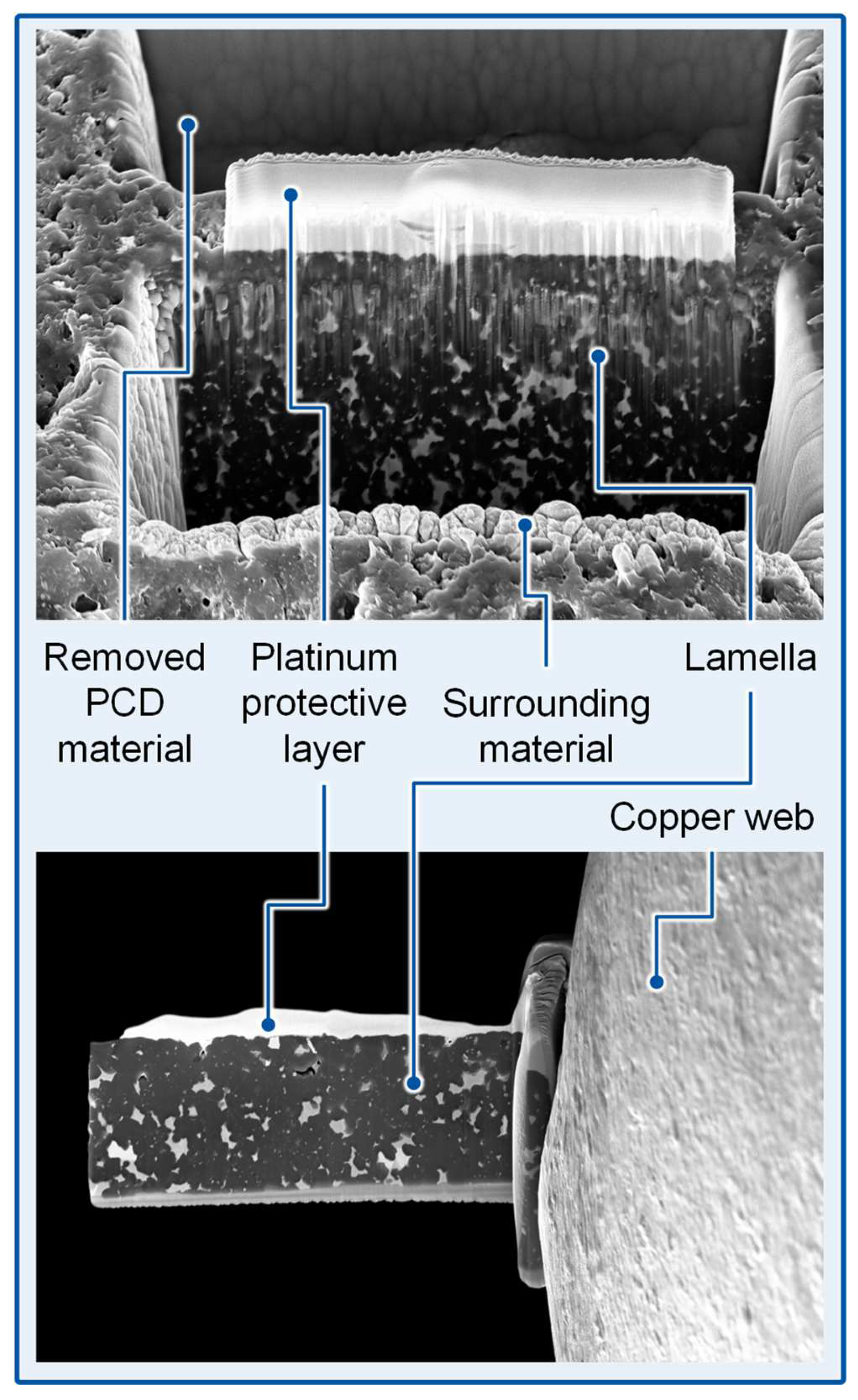
Figure 3B for the point marked in detail A. In this example, the EDX analysis led to the conclusion that the medium gray area represents a diamond (C) grain with a large amount of dislocations rather than a cobalt inclusion. It can be assumed that more dislocations were present in the lamella than could be identified within a single image because the visibility of dislocations strongly depends on the angle between the crystal planes and the electron beam within the microscope. The detection of copper (Cu) constituents could be traced back to the copper web used as a sample holder (see
Figure 2). Traces of copper can be detected in EDX point analyses several micrometers aside the sample holder because of electron backscattering and can thus be neglected for the further evaluation. The findings described above and displayed in
Figure 3 prove representative for the entire lamella, which was cut from the reference sample. It can be assumed that the cracks, dislocations, and stresses found in the reference sample were caused by the thermo-mechanical conditions in the sample manufacturing, including a high-pressure, high-temperature sintering process [
21].
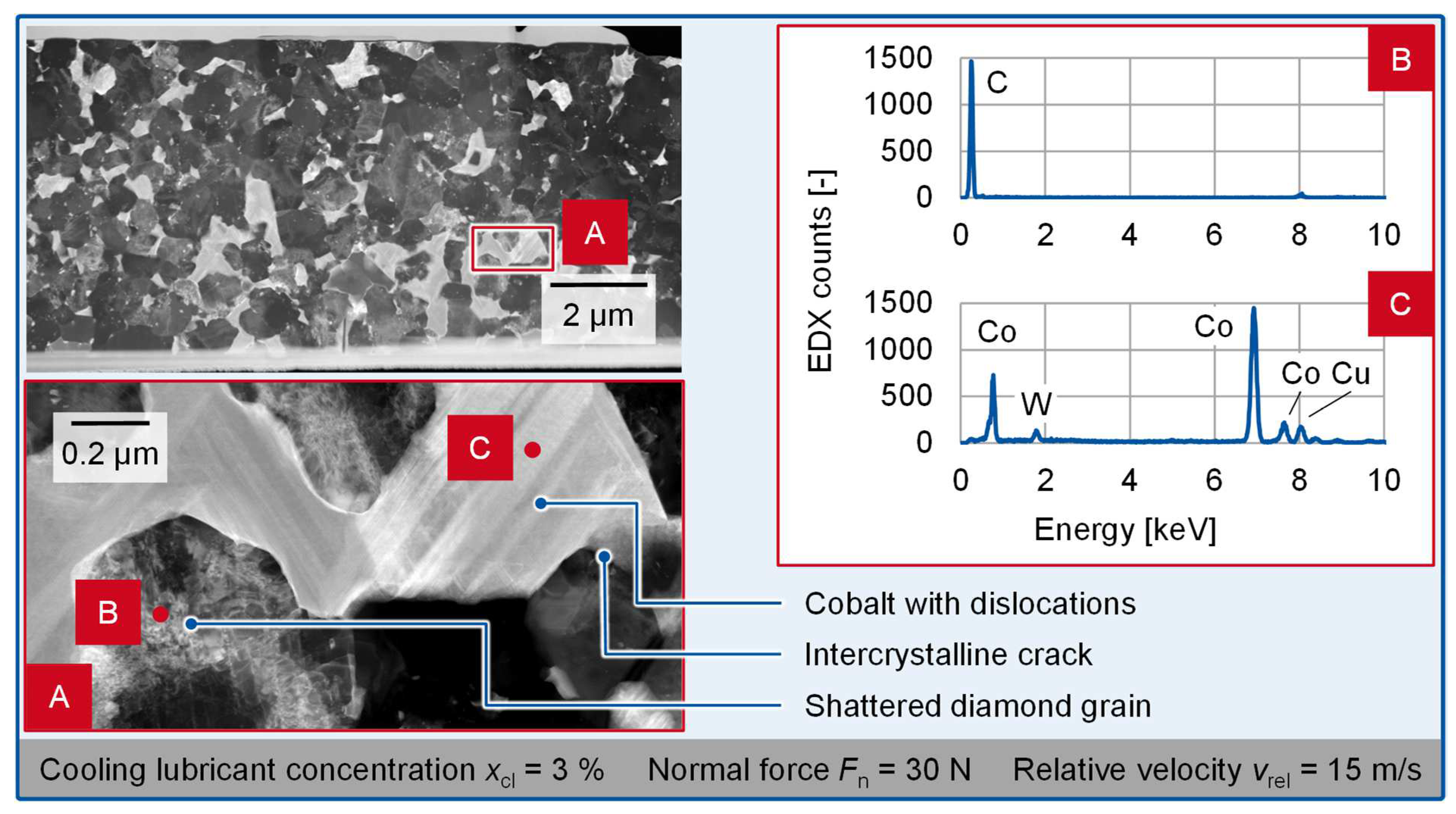
Figure 4 shows the STEM and EDX analysis of a sample ground with a relatively low thermo-mechanical load, as indicated by the grinding parameters used (normal force
Fn = 30 N, relative velocity
vrel = 15 m/s). It is to be noted that the top right-hand corner of the overview image appears slightly darker than the rest of the image. This is due to a thinner area within the lamella, which distorts the imaging fidelity. The contrast between the diamond and cobalt phase in the respective area as well as the part of the image outside the described area remain uncompromised. The microstructure was similar to the reference sample and also showed dislocations in both diamond and cobalt crystals (for example,
Figure 4A) as well as intercrystalline cracks. Furthermore, more shattered diamond grains were found within the lamella than within the reference sample. An example is displayed in the marked point B in
Figure 4A and verified through the EDX analysis given in
Figure 4B. This indicates that an additional mechanical load interfered with the microstructure in the grinding process. The intense and more frequently occurring dislocations in the cobalt phase attribute to the same conclusion. In the example of the marked point C in
Figure 4A, the EDX analysis detected traces of copper (Cu) and tungsten (W), as displayed in
Figure 4C. While the copper traces were already described for the reference sample (
Figure 3), the tungsten traces were not evident in any EDX analysis performed on the reference sample. Nevertheless, it can be argued that they were introduced from the cemented carbide substrate of the samples during the grinding process.
In
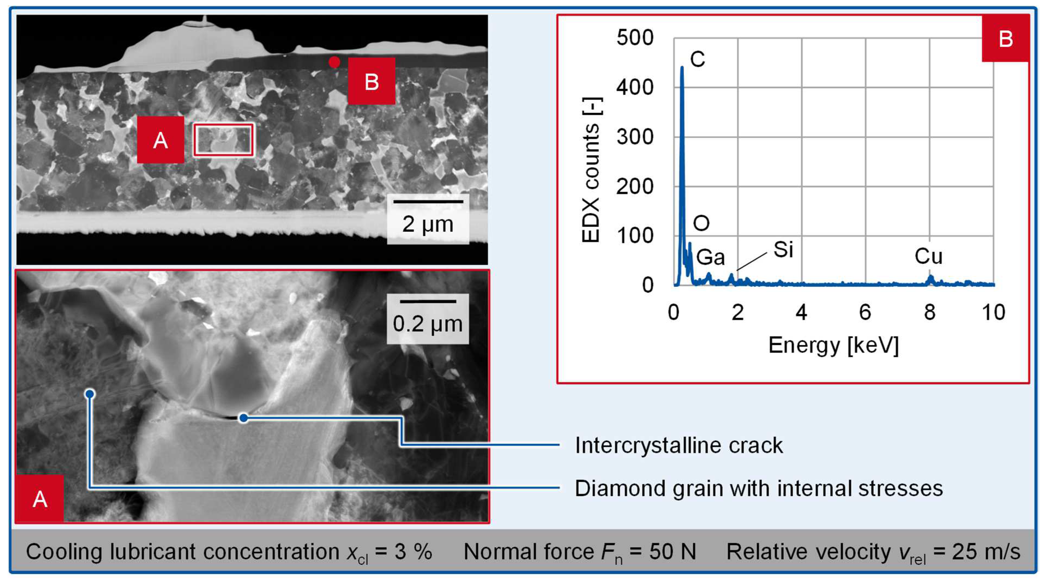
Figure 5, the test point with a relatively high thermo-mechanical load is focused (grinding parameters: normal force
Fn = 50 N, relative velocity
vrel = 25 m/s). Again, an overview STEM image of the lamella and a detailed view with a higher magnification (
Figure 5A) are given. It is obvious that below the platinum protective layer, which is shown as a bright strip on top of the PCD microstructure, there is an additional dark layer around point B. An EDX analysis (
Figure 5B) was performed, indicating that the layer mainly consists of carbon (C) and oxygen (O). The oxygen-containing layer was exclusively located on top of the sample, and no further EDX analysis throughout the lamella detected any further traces of oxygen. This leads to the assumption that the layer can be considered an impurity caused during the sample preparation or handling. Further peaks in the EDX spectrum can be interpreted as the presence of gallium (Ga) and silicon (Si). This can, on the one hand, be traced back to the FIB used to cut the lamella, which relied on a gallium ion beam. On the other hand, the silicon detections, together with the oxygen detection, lead to the assumption that the impurity layer was a ceramic phase. Additional EDX analyses of the vitrified grinding wheel bond used in the grinding process showed that the bond contained large amounts of silicon and oxygen as well. Therefore, the impurity is considered a fragment from the grinding wheel bond, introduced during grinding, and its occurrence is neglected for the further analysis and any conclusions made regarding the PCD. The analysis of the STEM-DF image of the lamella led to similar findings compared to the analysis of the sample ground at a low thermo-mechanical load and the analysis of the reference sample. The intensity and recognition density of these findings within the area of the lamella was greater than for the sample ground at the lower thermo-mechanical load. Examples for the identified phenomena are shown in
Figure 5A, such as intercrystalline cracks and diamond grains with signs of internal stresses.
When comparing the STEM analyses of the reference sample to the sample ground at a low thermo-mechanical load, it becomes obvious that no additional phenomena, especially no signs of additional thermal or mechanical material removal mechanisms, can be seen in the crystallographic structure of the samples. Moreover, the intensity and number of the present defects, such as intercrystalline cracks, dislocations in both phases, and internal stresses in diamond crystals, have increased over the grinding process. As these phenomena can be mainly attributed to mechanical load, and the EDX measurements did not indicate the occurrence of any thermally induced phenomena, the load collective during the grinding process appeared to be mechanically dominated.
An increased process load, introduced through an increase in both normal force
Fn and relative velocity
vrel by approximately 67% between the samples in
Figure 4 and
Figure 5, did not lead to the detection of thermal conversions within the EDX analyses either. The only oxidative process whose existence was presumed was not validated by multiple occurrences throughout the sample but was instead deemed a local phenomenon between the PCD microstructure itself and the platinum layer. It can therefore be attributed to the sample preparation or handling rather than the grinding process. The mechanically caused findings increased further in their prevalence. As a consequence, it can be concluded that the sample ground at the higher thermo-mechanical load was subjected to a higher mechanical load, while the thermal share of the load collective remained irrelevant.
The comparison of the samples summarized above implies that the grinding process of PCD with water-based cooling lubricants is strongly mechanically driven rather than thermally. This assumption is highly supported by the previous simulative study of the process conducted in [
16]. Together with the findings from the earlier single-grain contact experiments [
14], the grinding tests [
15], and the TEM analyses in the present study and the findings from the simulation [
16], an explanatory model for the grinding process of PCD with a water-based cooling lubricant is developed in the following paragraphs.
Schindler and Vits already presented explanatory models for the material removal mechanisms in the PCD grinding process and discussed the grinding wheel wear during grinding PCD with oil as a cooling lubricant. Both used comparable experimental materials, such as PCD and grinding wheel specifications, indicating that their results are generally comparable to the findings from the present work. Nevertheless, there are crucial differences between the works that lie in the process kinematics and the cooling lubricant type. Schindler’s work presented his assumption of partially thermal material removal mechanisms. Furthermore, he stated that the material removal mechanisms change with a certain load limit, even leading to different roughnesses of the ground surface [
7]. Vits, to an extent, disagreed with Schindler with regard to the material removal mechanisms relevant for the PCD grinding process, which he attributed to different experimental conditions and parameters in his work [
8]. The present work differs from both the studies of Schindler and Vits when the process kinematics and the cooling lubricant are considered. For example, Vits investigated a track-bound grinding process with oil as a cooling lubricant [
8], while the present study takes a force-bound grinding process with a water-based cooling lubricant into account. As a consequence of these differences, no previous explanatory model for the material removal mechanisms is directly applicable. Nevertheless, the model by Vits can serve as a structural basis for the explanatory model to be developed in this work.
Vits stated that after the first contact of the grinding wheel and the PCD workpiece, cracks are initiated and grow in both an intercrystalline and transcrystalline manner. After further strokes in the track-bound grinding process, the cracks propagate into the material, causing a weakening of the microstructure and the breakout of several diamond grains [
8]. This aligns well with the results of the present study, as intercrystalline cracks were frequently found in the TEM images, especially between a diamond grain and an underlying cobalt inclusion. The prevalence of this material removal mechanism increased with an increasing mechanical process load. Furthermore, some cracks were detected at diamond–diamond grain boundaries.
Vits attributed the observed intercrystalline cracks to two possible explanations. He assumed that the cobalt phase is exposed to a larger elastic deformation in the areas loaded by a diamond abrasive grain than a PCD diamond grain. Thus, shear stresses are introduced into the grain boundary between diamond and cobalt. In addition, Vits highlighted the thermal expansion coefficients of diamond
αdia and cobalt
αCo, which differ by a factor of 4.5 to 8 and cause internal stresses when the PCD structure is exposed to elevated temperatures. It should be noted that Vits already assumed that the thermal process loads have a minor influence on the material removal mechanisms than the mechanical process loads when grinding with oil as a cooling lubricant [
8]. In the experiments [
15] and simulations [
16] previous to this study as well as the experiments in the present study, even lower temperatures were found than in the investigations of Vits. Especially, all measured temperatures were far lower than the conversion temperatures of the diamond phase within the PCD, which are generally higher than 575 °C [
8]. Additionally, no clear signs of any thermally induced phenomena were identified in the TEM analysis. Hence, it can be assumed that the material removal in the grinding process of PCD with a water-based cooling lubricant is close to exclusively mechanically driven. Therefore, Vits’s explanation regarding shear stresses in the diamond–cobalt grain boundaries is considered transferrable to the present explanatory model, while his explanation referring to the thermal expansion coefficients
αi is considered not transferrable.
In the TEM analysis presented above, some diamond grains showed signs of internal stresses and dislocations. Nevertheless, transcrystalline cracks were rarely detected in this study. Although some occurrences of shattered diamond grains are to be noted, for which previous transcrystalline cracks can be considered a possible cause, the transcrystalline cracks appear to be less prevalent than in Vits’s investigations. Vits cited thermal alternating loads as a possible cause for the intercrystalline cracks [
8]. In light of the same background as described above with regard to the intercrystalline cracks, these loads can be ruled out as a cause for the transcrystalline cracks and the shattered diamond grains in the present study. It can be assumed that the lower prevalence of transcrystalline cracks in this study compared to the experiments by Vits is due to the lack of the share of cracks initiated by thermal causes.
The diamond grain breakouts directly at the surface, as described by Vits [
8], were not obvious in any of the TEM images analyzed for the present work. Therefore, it can be concluded that abrasion is a more dominant mechanism for the PCD grinding process with a water-based cooling lubricant. According to Vits, exceeding a certain limit process load is a necessary prerequisite for the increased occurrence of grain breakouts [
8]. This finding is congruent to the explanatory model of Schindler, who also investigated the material removal mechanisms in PCD grinding with oil as a cooling lubricant. He came to the conclusion that a critical area-specific normal force
F″
n in the grinding process is required to initiate the grain breakouts. Below this critical value, according to Schindler, the material removal is mainly thermally driven. The diamond grains undergo a graphitization and burning process, drastically decreasing their hardness and therefore leaving them in a state in which they are easy to remove for following abrasive grains. The result is a smooth-ground PCD surface with little to any diamond grain breakouts [
7]. Although Vits agreed with the observation described by Schindler, he stated that in the parameter range he investigated, thermo-physical phenomena do not seem to be the cause [
8]. The present study’s conclusion follows this assertion by Vits, as thermally induced phenomena can be excluded from the explanation, and microscopic abrasion processes are identified as the main cause for the smooth surfaces.
The data acquired through the present work proved insightful with regard to the material removal mechanisms during the grinding of PCD with a water-based cooling lubricant. According to the described comparison between the results of Vits [
8] and Schindler [
7], along with the results of the present work, an explanatory model for the material removal mechanisms in PCD grinding with water-based cooling lubricants was derived based on the explanatory model of Vits [
8].
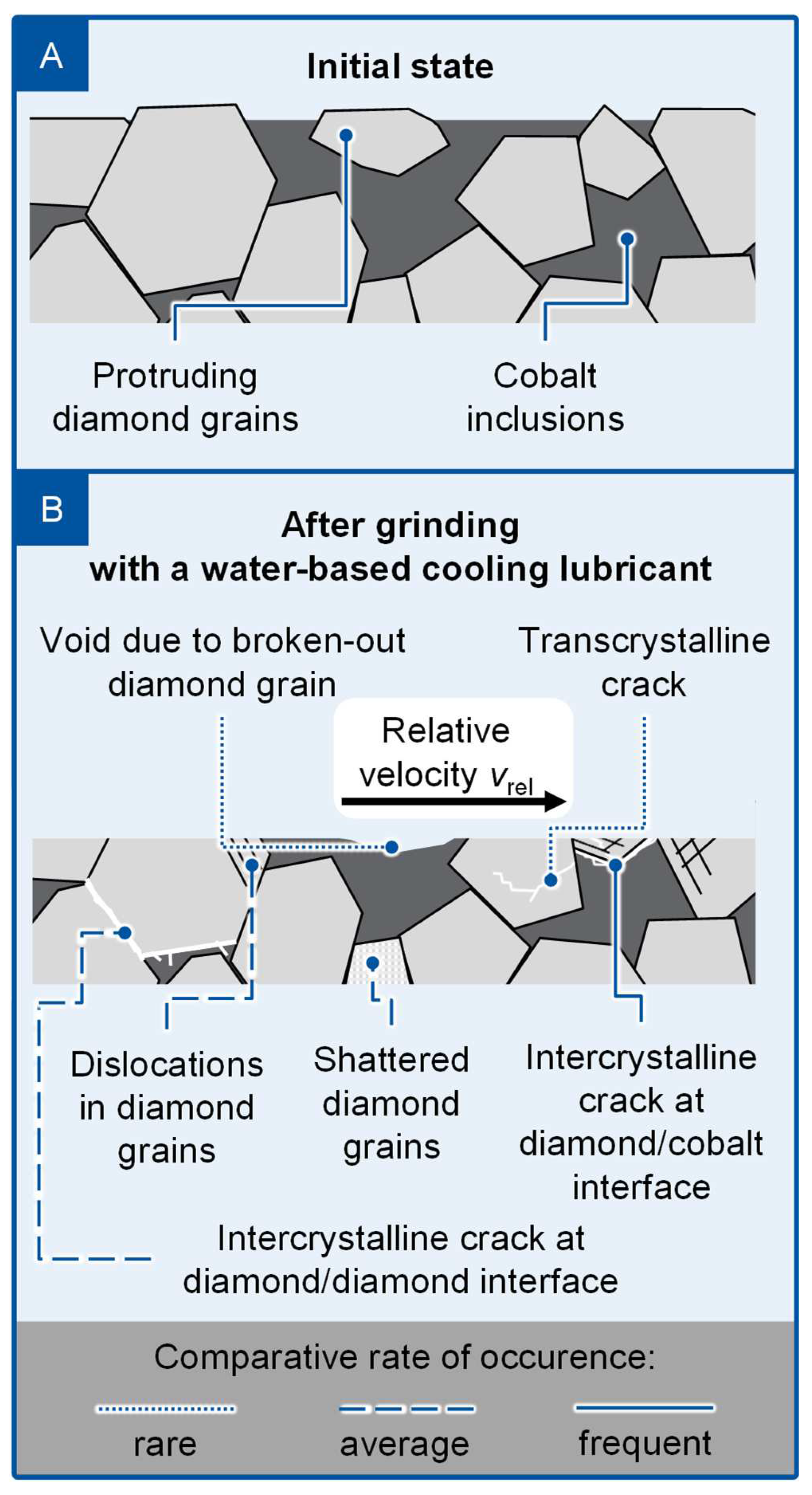
Figure 6 graphically displays a summary of the identified material removal mechanisms for the grinding process of PCD with a water-based cooling lubricant.
Figure 6A shows a depiction of the initial state of a PCD workpiece with protruding diamond grains, diamond grains situated below the surface, and cobalt inclusions around the diamond grain.
Figure 6B illustrates the condition of the PCD after the grinding process with a water-based cooling lubricant. Herein, intercrystalline cracks at the diamond–cobalt interface were identified as the most frequent material removal mechanism. Intercrystalline cracks at the diamond–diamond grain boundaries, meanwhile, are classified as a material removal mechanism of average rate of occurrence, alongside dislocations in diamond grains and shattered diamond grains. Voids at the PCD surface and transcrystalline cracks were considered as rarely occurring mechanisms.
3.2. Grinding Wheel Wear
The following paragraphs comprise the main results of the track-bound grinding experiments. Thereafter, an explanatory model for the grinding wheel wear is derived. As a macroscopic wear indicator, the grinding ratio
G was calculated. It is defined as the quotient of the material removal
Vw and the grinding wheel wear volume V
s. Due to this, a high grinding ratio
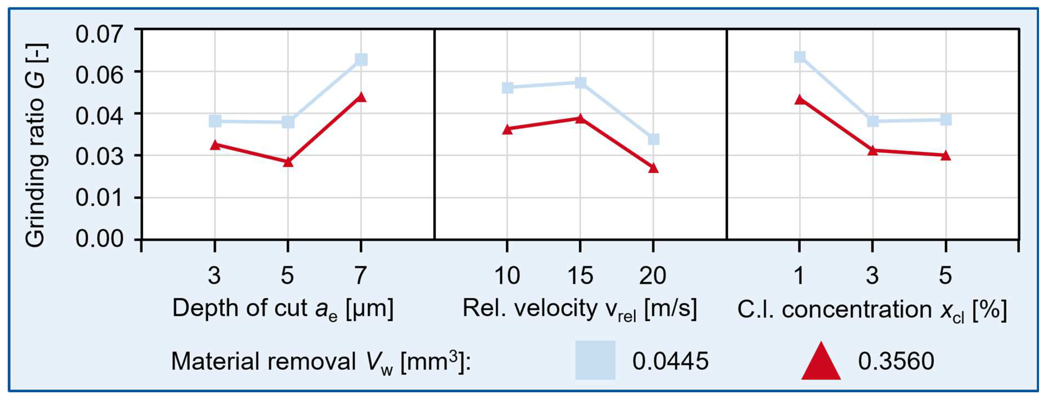
G attributes to sharp and efficient cutting behavior of the grinding wheel. In
Figure 7, a main effect diagram for the grinding ratio
G is displayed. At an increased material removal
Vw, the grinding ratio
G was reduced. It can be assumed that a less sharp grinding wheel topography caused this effect, which will be further assessed in the following microscopic wear analysis. Since an increased depth of cut
ae and a decreased relative velocity
vrel both lead to an increased grinding ratio
G, it can be assumed that high chip thicknesses
hcu are beneficial for an efficient cutting process, as also found by Vits [
8], for example. Low chip thicknesses
hcu as well as high cooling lubricant concentrations
xcl assumably lead to a slippage effect between the grinding wheel and the PCD workpiece, decreased the grinding ratio
G and increased abrasive grinding wheel wear.
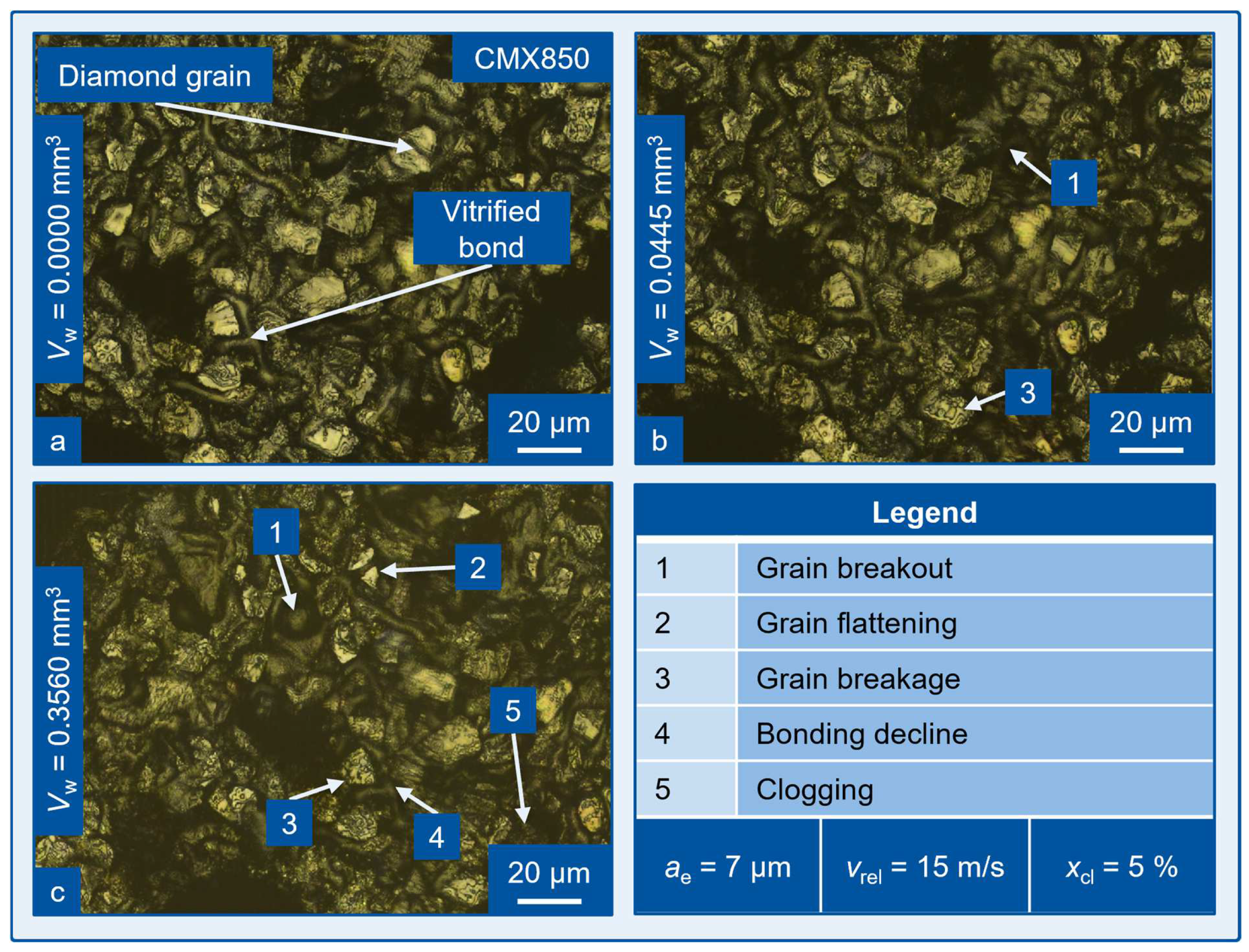
The microscopic evaluation of the grinding wheel wear provided further insight into the present wear mechanisms, which enabled the confirmation and extension of the above-mentioned explanatory approaches to the grinding wheel wear. A representative example for an LSM image series is shown in
Figure 8. The same section of the grinding layer is displayed after the dressing process and at the material removal stages also used in
Figure 7. The grinding wheel wear mechanisms identified are marked within the images.
The key findings from the analysis of all produced images together with the macro wear analysis include the reduction in grain breakouts, grain flattening, and grain breakage with an increased depth of cut
ae and thus increased grinding ratio
G. Furthermore, the clogging of pores intensified with an increased relative velocity
vrel, presumably with the cobalt phase of the PCD workpieces, leading to a decreased grinding ratio
G. The abrasive wear was identified as a dominant wear mechanism, which resembles the results of Vits for the grinding of PCD with oil as a cooling lubricant [
8]. No signs of thermally induced grinding wheel wear were found within the images.
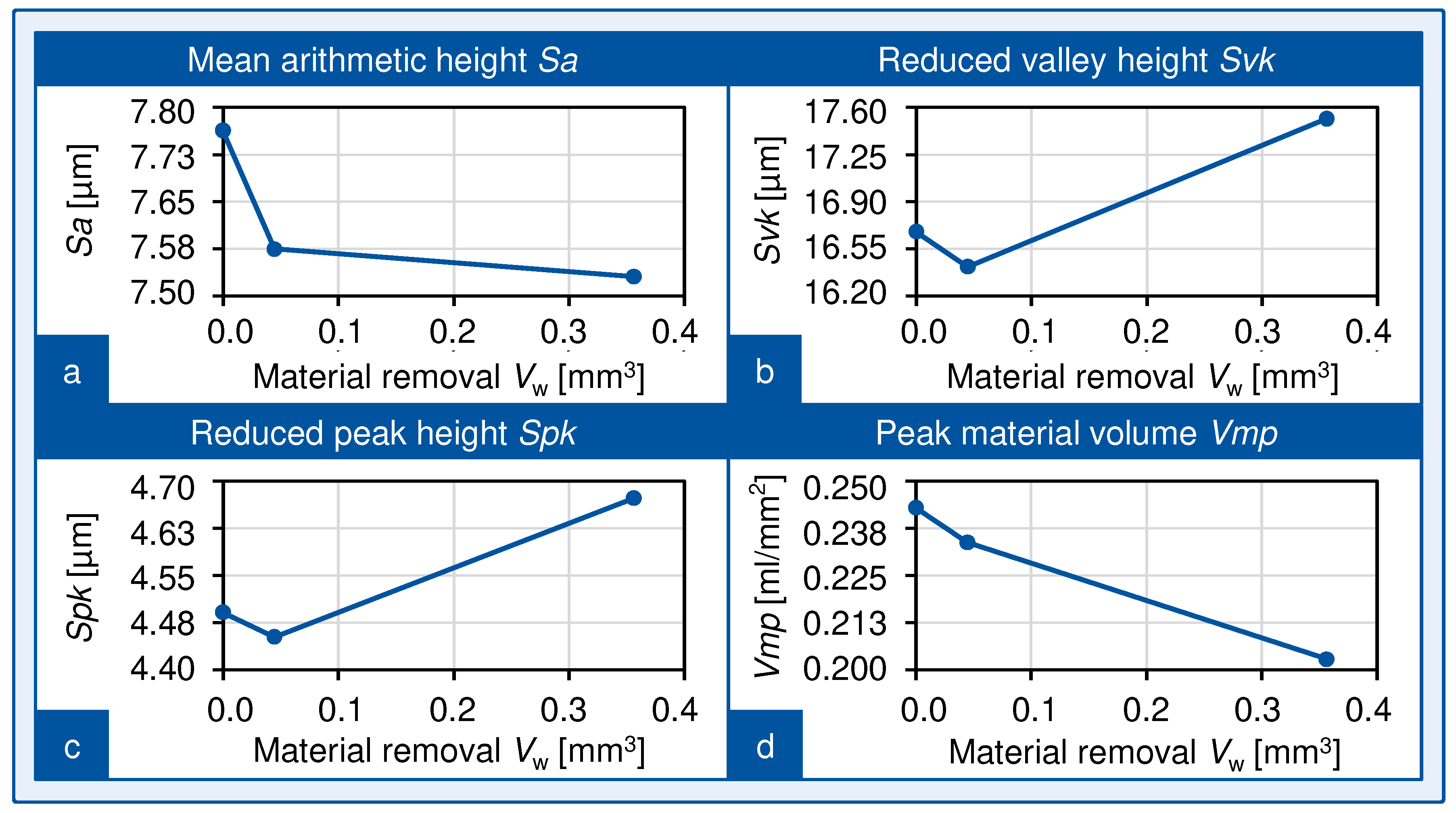
Static topography parameters were deduced from the three-dimensional LSM images, as shown in
Figure 9. The mean arithmetic height
Sa dropped quickly within the initial wear of the grinding wheel, followed by a slow and continuous wear behavior towards higher material removal
Vw. The reduced valley height
Svk and reduced peak height
Spk decreased initially and increased again at later wear states, leading to the assumption that the wear mechanism of grain breakout did not entirely end after the initial wear phase, but was rather reduced to a smaller extent. Therefore, new and sharp cutting edges came into contact with the workpiece. This self-sharpening effect was similarly observed by Vits [
8]. The peak material volume
Vmp decreased continuously. This can be explained through abrasive wear of the grinding wheel throughout the grinding process.
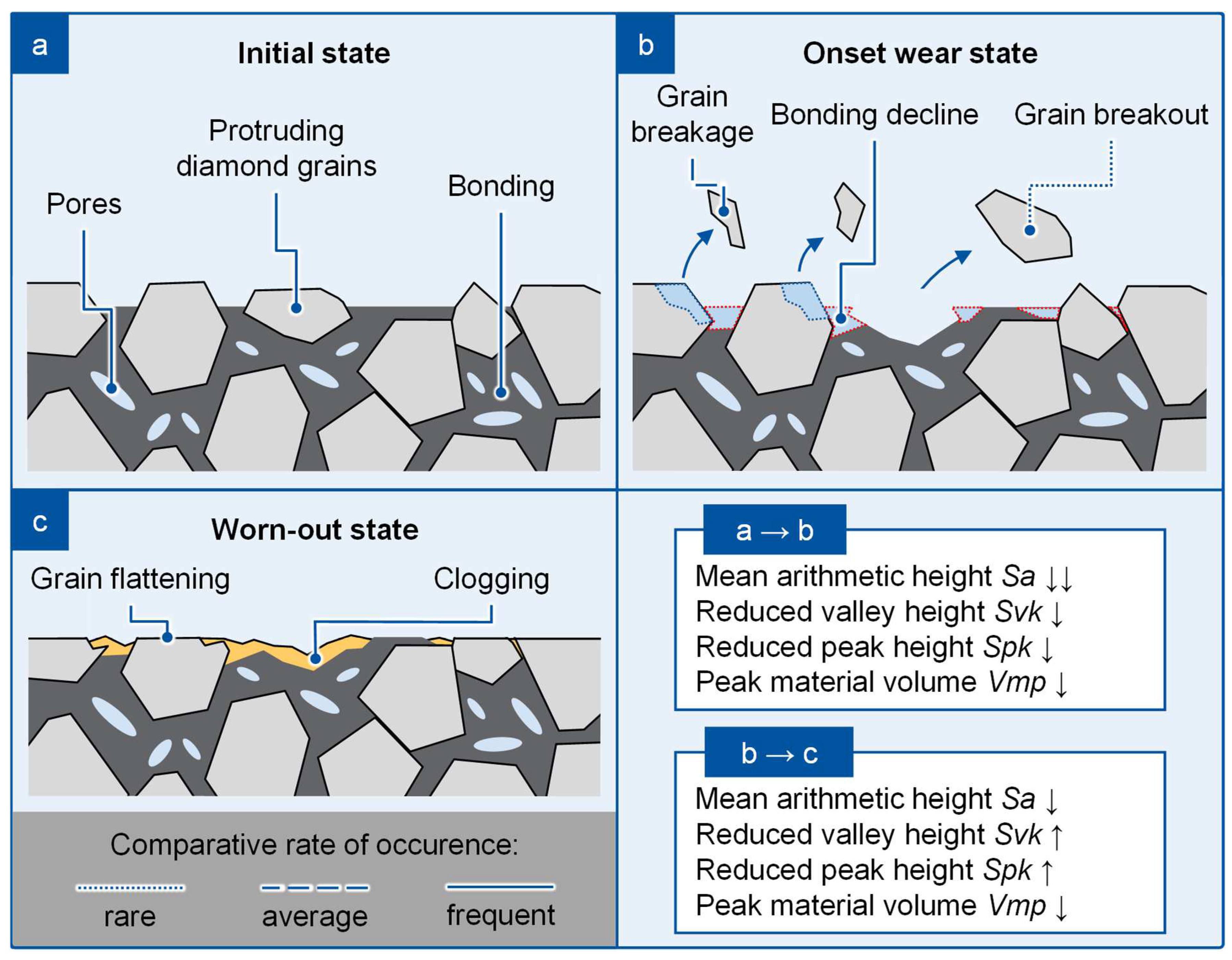
The results of the macro and micro wear analysis presented above have subsequently been used to deduce an explanatory model for the grinding wheel wear mechanisms while grinding PCD with a water-based cooling lubricant. During the initial wear of the grinding wheel after the dressing process, the wear mechanisms of bonding declined, and grain breakage and grain breakout were found to be dominant. This led to the changes in the static topography parameters displayed in
Figure 9 and thus to the early decrease in the effective roughness depth of the grinding wheel. Within the following continuous wear segment, the effective roughness depth decreased further but at a lower rate than before because the dominant wear mechanisms were abrasive wear and clogging of the grinding wheel. These findings are summarized in
Figure 10.


