
Review of Turbine Film Cooling Technology for Marine Gas Turbines


Abstract
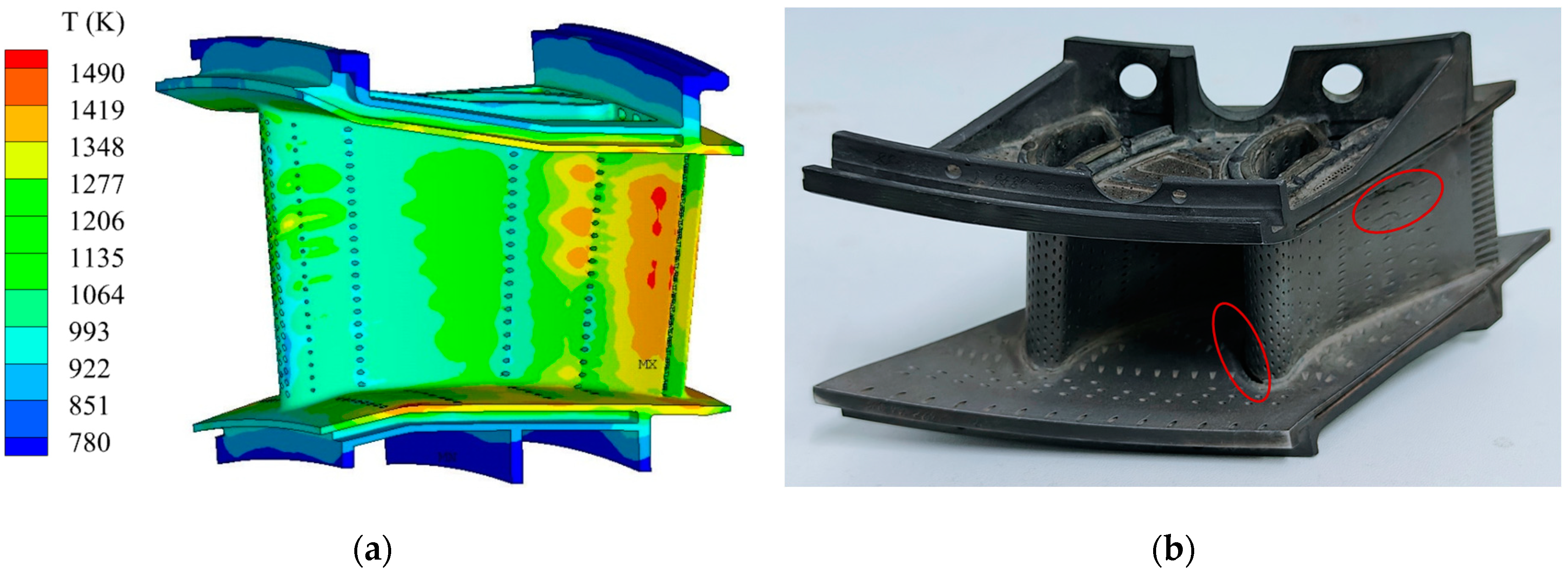
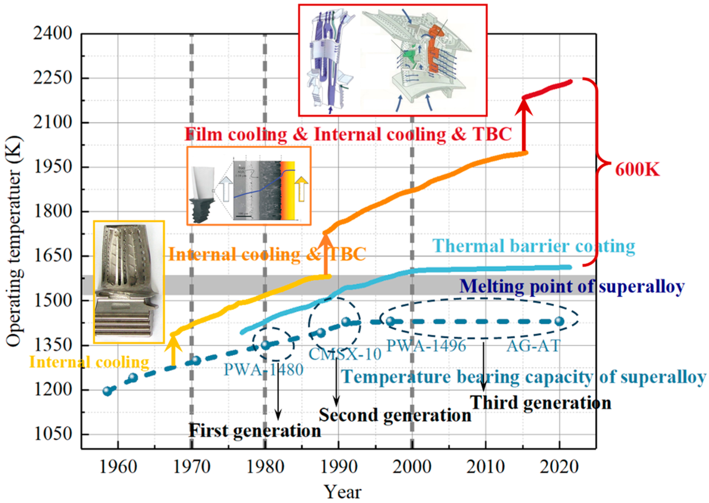
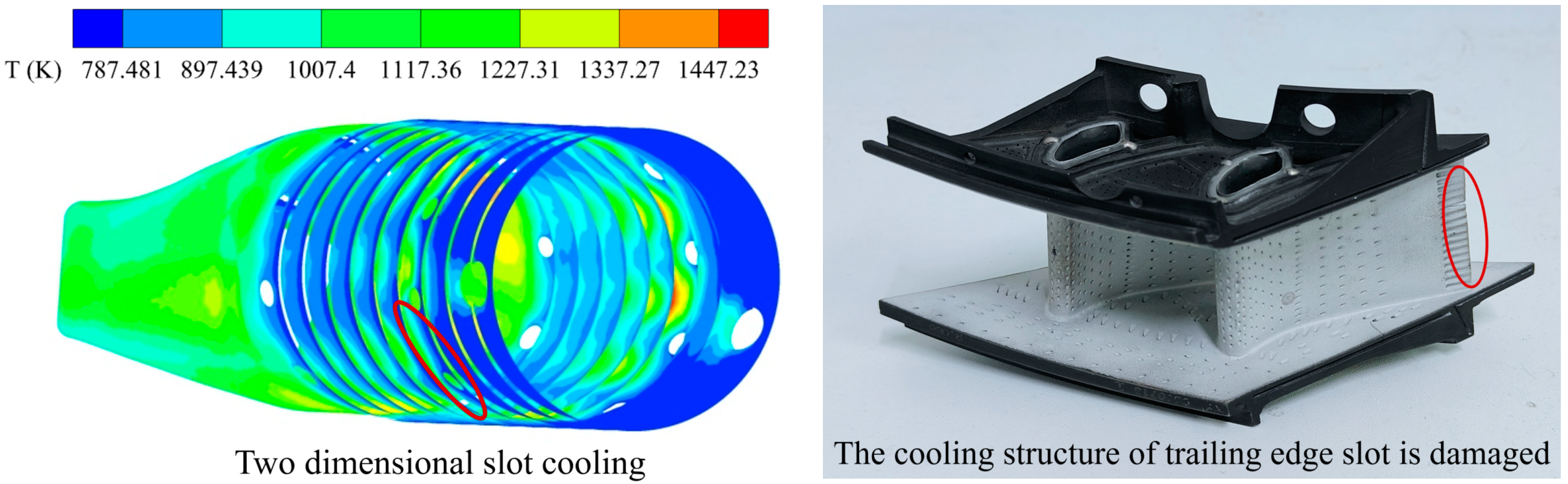
1. Introduction
2. Development of Configuration Design of Turbine Film Holes
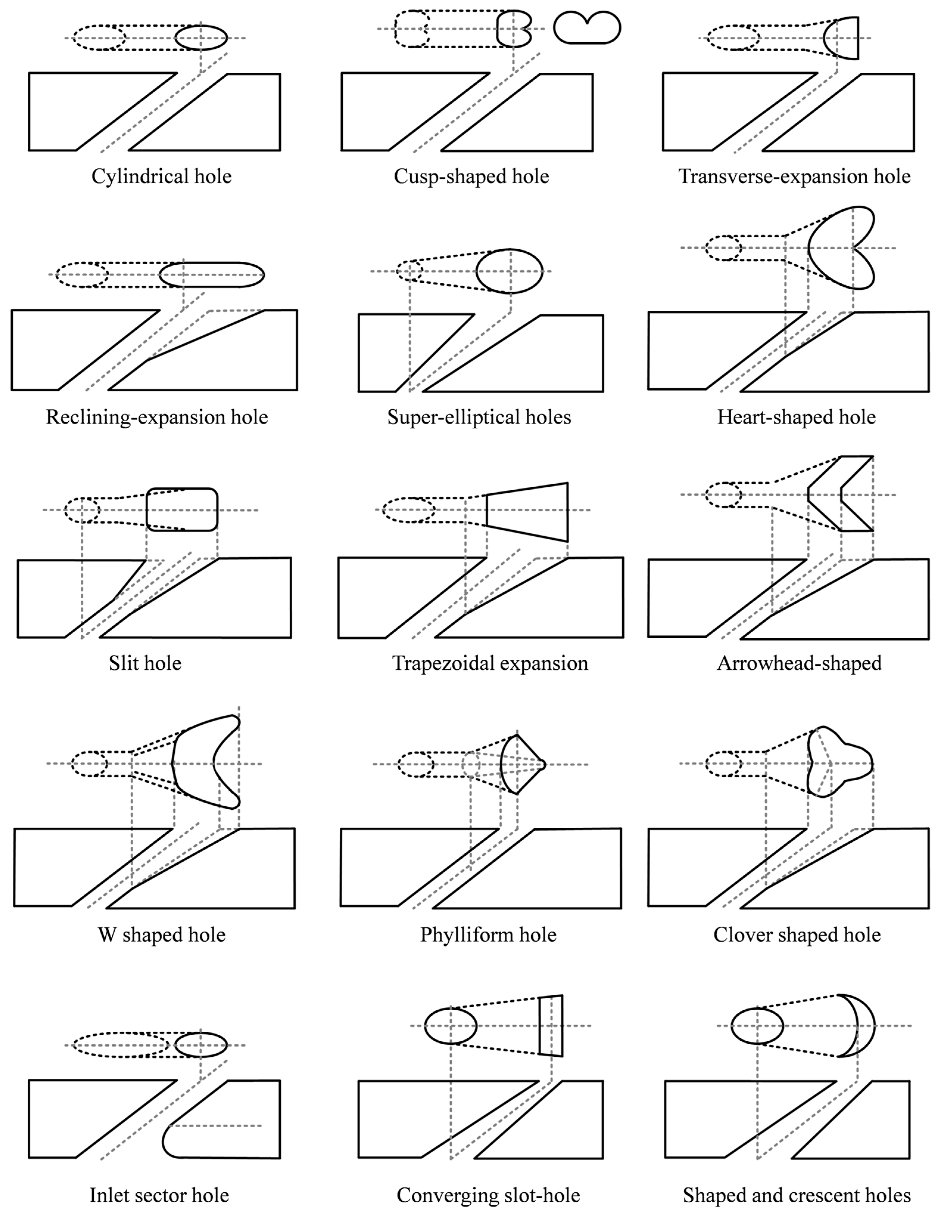
2.1. Shaped Hole
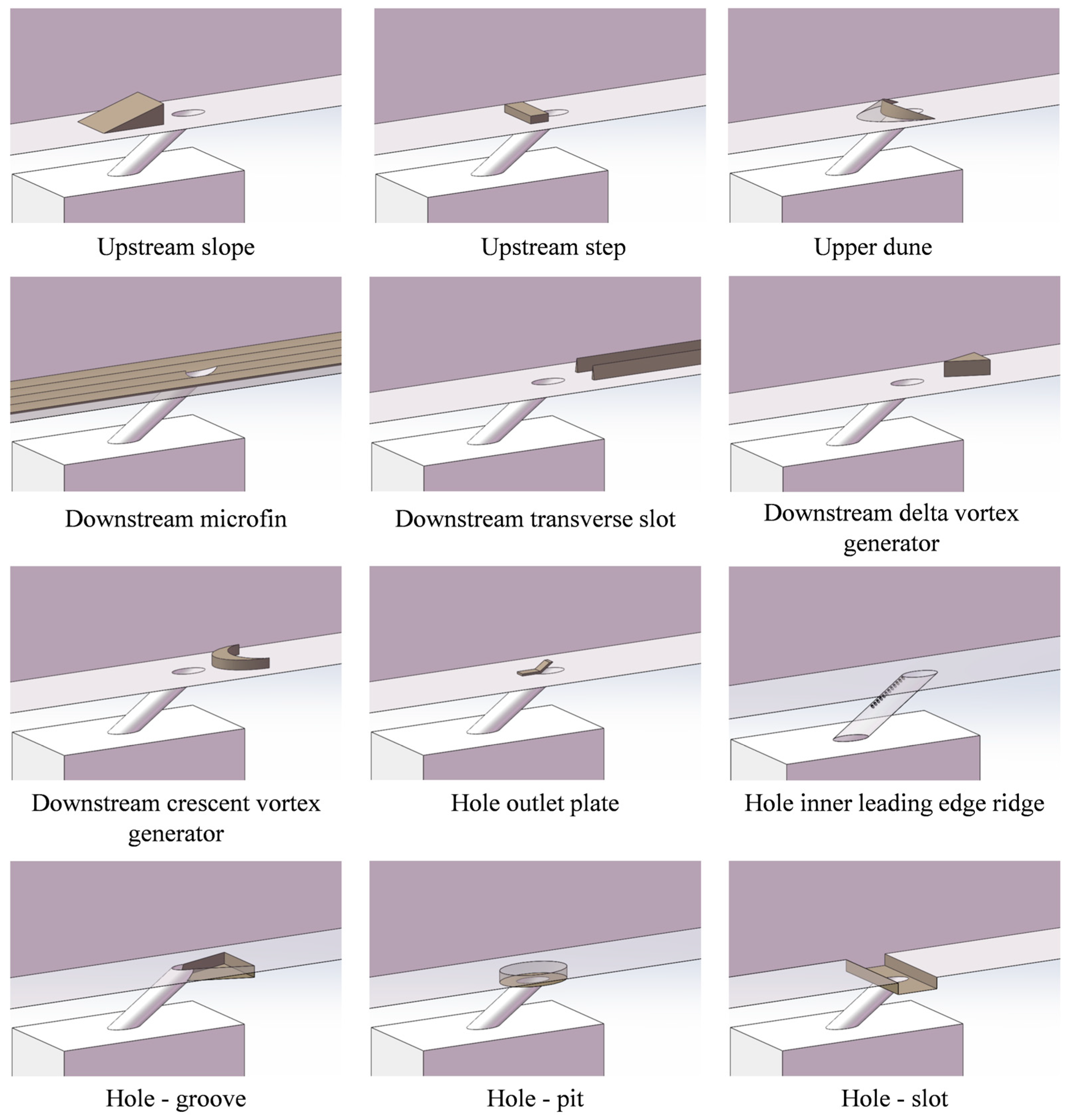
2.2. Film Hole with Auxiliary Structure
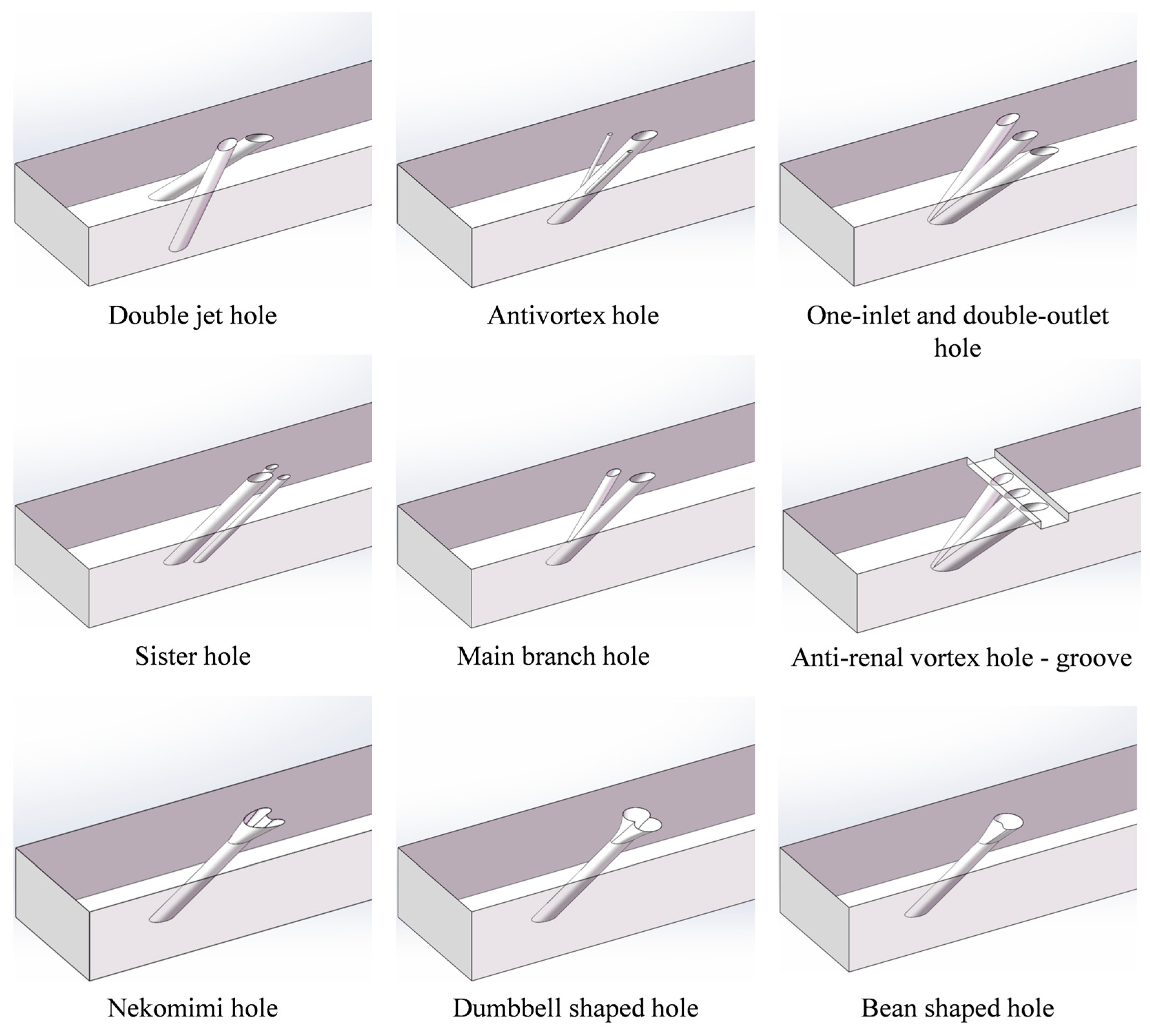
2.3. Combined Film Hole
2.4. Development Trend of Film Hole Configuration
3. Development of Turbine Film Hole Arrangement
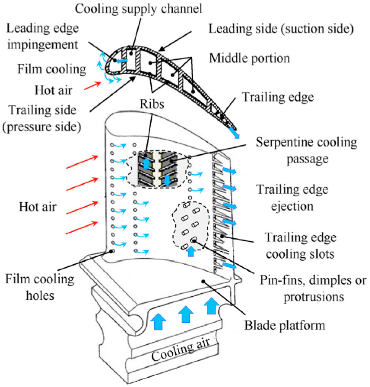
3.1. Arrangement of Film Holes in Turbine Blades
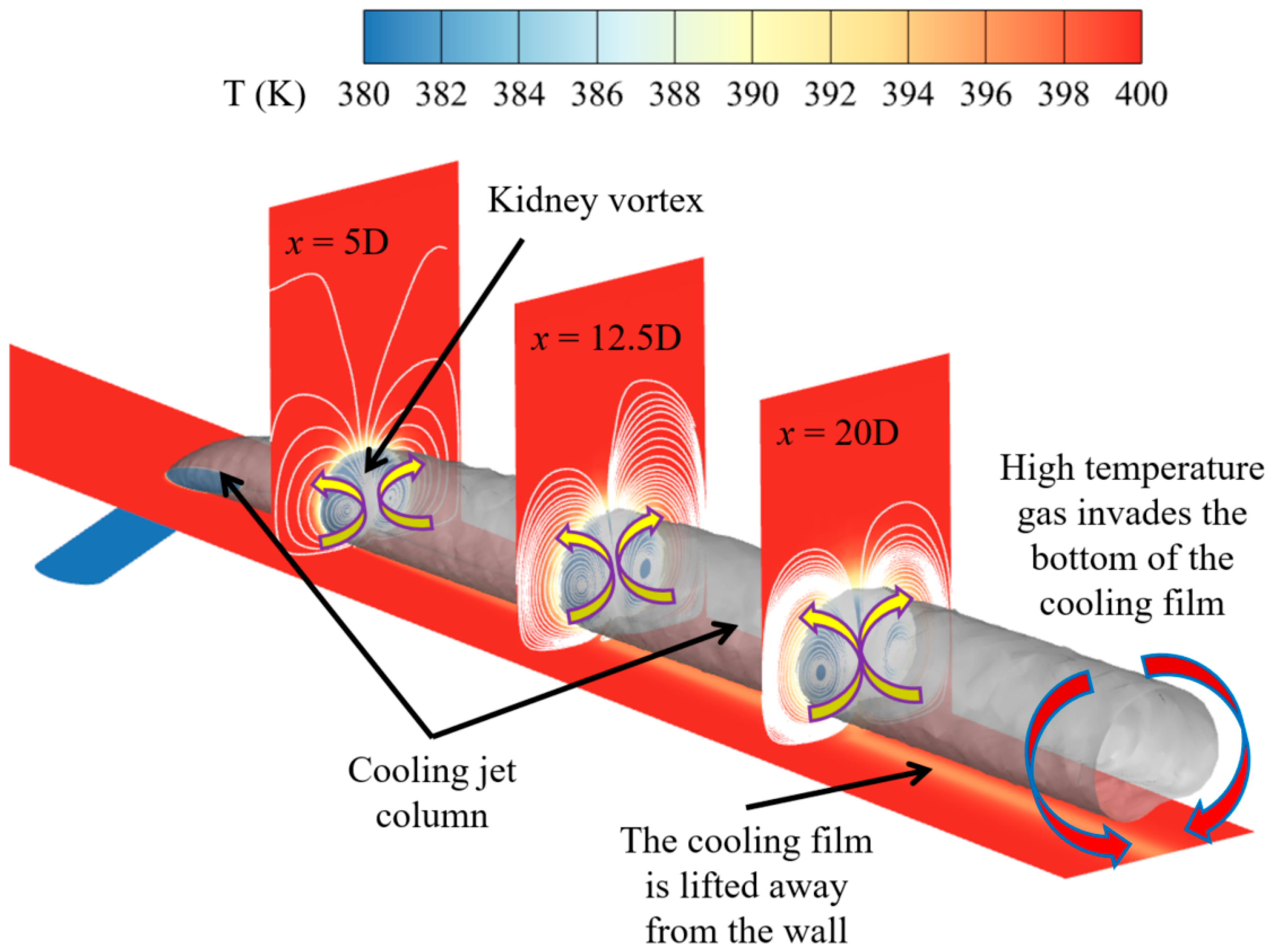
3.2. Flow Characteristics of Cascade Channel Region
3.3. Arrangement of Film Holes on Turbine Endwall
4. Research Status and Development Trend Analysis
- Various types of shaped holes, auxiliary devices, and combined film holes can improve film cooling performance; however, they still face numerous challenges in practical applications, such as stress concentration, processing technology, and processing costs. This has led many studies to remain at the basic research stage, making it difficult to apply them to engineering practices. Furthermore, the optimized film hole arrangements typically perform well only under specific operating conditions. When geometric structure or inlet conditions change, the performance tends to degrade, leading to poor versatility and stability. Therefore, designing new, easily manufacturable, high-efficiency film hole configurations and further expanding their stable operating range is an important development direction.
- There is a significant discrepancy between experimental studies and real-world operating conditions. Due to the difficulty of simulating actual high-temperature conditions in experimental setups, many researchers adopt reverse heat transfer methods for experimental studies, where secondary flow is heated to create a temperature difference between the mainstream and the secondary flow [167]. However, the extent to which reverse heat transfer affects cooling performance prediction, and how to more accurately assess the comprehensive cooling performance of turbines under experimental conditions, are critical issues that must be addressed in turbine cooling structure design for engineering applications. Therefore, it is essential to validate the reverse heat transfer method, assess its applicable range, and, when experimental conditions exceed the applicable range, use related theories to correct its predictive performance. This is key to overcoming the bottleneck in film cooling prediction.
- The film hole arrangement of turbine components is generally designed separately for blades and endwalls, which cannot integrate multiple critical factors. In particular, the effects of coupled heat transfer conditions and the mechanisms of inter-row cooling jet interactions remain unclear, leading to design guidelines for turbine component film hole arrangements still relying primarily on traditional operational experience. Therefore, it is urgent to develop a film hole arrangement guideline that is suitable for various types of film holes and components with temperature differences at the thermal end, to fill the gap in future film cooling optimization design technologies.
5. Conclusions
Author Contributions
Funding
Data Availability Statement
Acknowledgments
Conflicts of Interest
References
- Kang, Y.J.; Jeong, J.Y.; Kim, H.J.; Kim, G.M.; Kwak, J.S. Effect of Relative Location of Film Cooling Hole With Internal Angled Ribs on the Film Cooling Effectiveness of a Gas Turbine Blade. In Proceedings of the ASME Turbo Expo 2024, London, UK, 24–28 June 2024; p. 87998. [Google Scholar]
- He, Y.; Yao, R.; He, F.; Ma, L.; Chen, J.; Song, W.; Pu, J.; Wang, J. Effect of pulsed coolant injection on unsteady film cooling characteristics with serrated trench design. Int. J. Therm. Sci. 2024, 201, 108997. [Google Scholar] [CrossRef]
- Jia, Y.H.; Liu, Y.B.; He, X.; Meng, Z.W.; Zhao, S. Investigation on the arrangement guideline of film holes along the conjugate temperature difference in turbine guide vane. Chin. J. Aeronaut. 2024, 103400. [Google Scholar]
- Jia, Y.H.; Liu, Y.B.; Meng, Z.W.; Yin, W.T.; Hua, W.Z. Numerical study on film cooling effectiveness from spiral-channel hole. Int. Commun. Heat Mass Transf. 2023, 143, 106716. [Google Scholar] [CrossRef]
- Mansouri, Z. Unsteady simulation of flow and heat transfer in a transonic turbine stage under non-uniform inlet conditions. Int. Commun. Heat Mass Transf. 2021, 129, 105660. [Google Scholar] [CrossRef]
- Sounik, J.L.; Wright, L.M. Analysis of the Instantaneous Film Cooling Effectiveness on Showerhead Film Cooling Using Fast Response Pressure Sensitive Paint (Fast-PSP). In Proceedings of the ASME Turbo Expo 2024, London, UK, 24–28 June 2024; p. 87998. [Google Scholar]
- Li, M. Analysis to Ultra High Bypass Ratio Turbofan Engine Roadmap of ATI. Aerosp. Power 2023, 39, 10–15. (In Chinese) [Google Scholar]
- Park, J.; Park, S.J.; Bang, K.M.; Jin, H. Influence of external thermal resistance on thermoelectric cooling in thermal management systems: Operating modes and material selection. Energy Convers. Manag. 2025, 333, 119806. [Google Scholar] [CrossRef]
- Chen, W.H.; Zhang, H.G. Current situation and future development prospect of aero-engine manufacturing industry in Russia. Def. Ind. 2015, 2015, 73–80. (In Chinese) [Google Scholar]
- Jeong, J.Y.; Jo, Y.R.; Kang, M.S.; Kang, Y.J.; Kwak, J.S. Film Cooling Effectiveness and Flow Structures of Butterfly-Shaped Film Cooling Hole Configuration. In Proceedings of the ASME Turbo Expo 2023, Boston, MA, USA, 26–30 June 2023; p. 87004. [Google Scholar]
- Barigozzi, G.; Perdichizzi, A.; Abba, L.; Pestelli, L. Platform film cooling investigation on an HP nozzle vane cascade with discrete shaped holes and slot film cooling. In Proceedings of the of the ASME Turbo Expo 2020, Virtual, 21–25 September 2020; p. 84171. [Google Scholar]
- Wang, B.; Wang, F.; Zhang, X.; Wang, J.; Xue, T. Numerical analysis of cooling efficiency for turboshaft engines with converging-diverging film holes. Int. J. Therm. Sci. 2023, 185, 108044. [Google Scholar] [CrossRef]
- Meetham, G.W. High-temperature materials—A general review. J. Mater. Sci. 1991, 26, 853–860. [Google Scholar] [CrossRef]
- Meng, Z.W.; Liu, Y.B.; Li, Y.J.; Zhang, Y.S. An analytical model for predicting residual stress in TBC-film cooling system considering non-uniform temperature field. J. Appl. Phys. 2021, 129, 135301. [Google Scholar] [CrossRef]
- Zhang, W.; Zeng, R.; Lu, J.; Liu, S.; Cha, H.; Li, G. Investigation of cooling performance degradation of impingement/effusion structure on pressure side of nozzle guide vane. Case Stud. Therm. Eng. 2022, 33, 101991. [Google Scholar] [CrossRef]
- Jia, Y.H.; Liu, Y.B.; Meng, Z.W.; He, X.; Liu, Y. The film cooling performance of spiral-channel holes on turbine guide vane. Case Stud. Therm. Eng. 2024, 53, 103846. [Google Scholar] [CrossRef]
- Jia, Y.; Liu, Y.; He, X.; Meng, Z.; Liu, Y. Effects of blowing ratio, hole position, and mainstream Reynolds number on film cooling effectiveness and energy loss of spiral-channel holes. Int. J. Therm. Sci. 2024, 195, 108662. [Google Scholar] [CrossRef]
- Li, G.; Wan, L. Film cooling improvement of dovetail hole compared to cylindrical hole at different hole row locations on nozzle guide vane. Case Stud. Therm. Eng. 2023, 45, 103015. [Google Scholar] [CrossRef]
- Wang, J.; Cui, P.; Vujanović, M.; Baleta, J.; Duić, N.; Guzović, Z. Effects of surface deposition and droplet injection on film cooling. Energy Convers. Manag. 2016, 125, 51–58. [Google Scholar] [CrossRef]
- Wang, Y.; Zhou, L.; Kang, X.; Huang, Q.; Shi, X.; Wang, C. Experimental and numerical optimization of direct-contact liquid film cooling in high concentration photovoltaic system. Energy Convers. Manag. 2017, 154, 603–614. [Google Scholar] [CrossRef]
- Krishna Anand, V.G.; Parammasivam, K.M. Thermal barrier coated surface modifications for gas turbine film cooling: A review. J. Therm. Anal. Calorim. 2021, 146, 545–580. [Google Scholar] [CrossRef]
- Zhang, X.; Zhao, Y.; Yang, C. Recent developments in thermal characteristics of surface dielectric barrier discharge plasma actuators driven by sinusoidal high-voltage power. Chin. J. Aeronaut. 2023, 36, 1–21. [Google Scholar] [CrossRef]
- Fu, Z.; Zhu, H.; Cheng, L.; Jiang, R. Experimental investigation on the effect of mainstream turbulence on full coverage film cooling effectiveness for a turbine guide vane. J. Therm. Sci. 2019, 28, 145–157. [Google Scholar] [CrossRef]
- Ni, H.; Jiang, P.; Peng, W.; Sun, X.; Zhu, Y. An innovative design for measuring the enhanced mixing effect of a shock wave on supersonic film cooling. Int. Commun. Heat Mass Transf. 2021, 122, 105132. [Google Scholar] [CrossRef]
- Pu, J.; Zhang, T.; Wang, J. Experimental study of combined influences of wall curvature and compound angle on film cooling effectiveness of a fan-shaped film-hole. Int. Commun. Heat Mass Transf. 2022, 130, 105834. [Google Scholar] [CrossRef]
- Zhang, J.Z.; Zhang, S.C.; Wang, C.H.; Tan, X.M. Recent advances in film cooling enhancement: A review. Chin. J. Aeronaut. 2020, 33, 1119–1136. [Google Scholar] [CrossRef]
- Yeranee, K.; Yu, R.A.O. A review of recent studies on rotating internal cooling for gas turbine blades. Chin. J. Aeronaut. 2021, 34, 85–113. [Google Scholar] [CrossRef]
- Cui, Y.; Shi, X.; Huang, Q.; Kang, X. Experimental study on direct-contact liquid film cooling simulated dense-array solar cells in high concentrating photovoltaic system. Energy Convers. Manag. 2017, 135, 55–62. [Google Scholar]
- Bogard, D.G.; Thole, K.A. Gas turbine film cooling. J. Propuls. Power 2006, 22, 249–270. [Google Scholar] [CrossRef]
- Zhou, Z.; Li, H.; Xie, G.; You, R. Film Cooling Performance on Turbine Blade Suction Side With Various Film Cooling Hole Arrangements. In Proceedings of the ASME Turbo Expo 2020, Virtual, 21–25 September 2020; p. 84171. [Google Scholar]
- Wang, L.; Chu, T.; Yuan, S.; Zhou, P.; Zhao, W.C.; Zheng, X.B.; Xia, M.P. Advances and future perspectives in thermoelectric cooling technology. Energy Convers. Manag. 2025, 332, 119621. [Google Scholar] [CrossRef]
- Goldstein, R.J.; Eckert, E.R.G.; Ramsey, J.W. Film cooling with injection through holes: Adiabatic wall temperatures downstream of a circular hole. J. Eng. Gas Turbines Power 1968, 90, 384–393. [Google Scholar] [CrossRef]
- Blair, M.F. An Experimental Study of Heat Transfer and Film Cooling on Large-Scale Turbine Endwalls. In Proceedings of the ASME Turbo Expo 1974, Zurich, Switzerland, 31 March–4 April 1974. [Google Scholar]
- Wang, Y.P.; Jiang, P.X. The separation vortex model is used to calculate the gas film cooling of inclined cylindrical holes. J. Eng. Thermophys. 2005, 26, 668–670. (In Chinese) [Google Scholar]
- Andreopoulos, J. Measurements in a jet-pipe flow issuing perpendicularly into a cross stream. J. Fluids Eng. Trans. ASME 1982, 104, 493–499. [Google Scholar] [CrossRef]
- Walters, D.K.; Leylek, J.H. A detailed analysis of film-cooling physics: Part I-Streamwise injection with cylindrical holes. J. Turbomach. 2000, 122, 102–112. [Google Scholar] [CrossRef]
- Kusterer, K.; Bohn, D.; Sugimoto, T.; Tanaka, R. Double-jet ejection of cooling air for improved film cooling. J. Turbomach. 2007, 129, 809–815. [Google Scholar] [CrossRef]
- He, J.; Yao, J.; Yang, X.; Zhang, K.; Lei, J.; Xie, G. Investigation on overall performance of double-jet film holes with various spanwise distance. Int. J. Therm. Sci. 2023, 183, 107841. [Google Scholar] [CrossRef]
- Goldstein, R.J.; Eckert, E.R.G.; Burggraf, F. Effects of hole geometry and density on three-dimensional film cooling. Int. J. Heat Mass Transf. 1974, 17, 595–607. [Google Scholar] [CrossRef]
- Gritsch, M.; Colban, W.; Schär, H.; Döbbeling, K. Effect of hole geometry on the thermal performance of fan-shaped film holes. J. Turbomach. 2005, 127, 718–725. [Google Scholar] [CrossRef]
- Zhou, W.; Peng, D.; Wen, X.; Liu, Y.; Hu, H. Unsteady analysis of adiabatic film cooling effectiveness behind circular, shaped, and sand-dune-inspired film holes: Measurement using fast-response pressure-sensitive paint. Int. J. Heat Mass Transf. 2018, 125, 1003–1016. [Google Scholar] [CrossRef]
- Lee, K.D.; Kim, K.Y. Surrogate based optimization of a laidback fan-shaped hole for film-cooling. Int. J. Heat Fluid Flow 2011, 32, 226–238. [Google Scholar] [CrossRef]
- Huang, Y.; Zhang, J.; Wang, C. Multi-objective optimization of round-to-slot film holes on a flat surface. Aerosp. Sci. Technol. 2020, 100, 105737. [Google Scholar] [CrossRef]
- Colban, W.; Thole, K. Influence of hole shape on the performance of a turbine vane endwall film-cooling scheme. Int. J. Heat Fluid Flow 2007, 28, 341–356. [Google Scholar] [CrossRef]
- Barigozzi, G.; Benzoni, G.; Franchini, G.; Perdichizzi, A. Fan-shaped hole effects on the aero-thermal performance of a film-cooled endwall. J. Turbomach. 2006, 128, 43–52. [Google Scholar] [CrossRef]
- Liu, J.H.; Liu, Y.B.; Liu, L. Film cooling modeling of a turbine vane with multiple configurations of holes. Case Stud. Therm. Eng. 2018, 11, 71–80. [Google Scholar] [CrossRef]
- Oliver, T.A.; Bogard, D.G.; Moser, R.D. Large eddy simulation of compressible, shaped-hole film cooling. Int. J. Heat Mass Transf. 2019, 140, 498–517. [Google Scholar] [CrossRef]
- Liu, Z.; Yang, X.; Feng, Z.P. Heat transfer and cooling of gas turbine blades: Film cooling. Therm. Turbine 2014, 43, 1–9. (In Chinese) [Google Scholar]
- Jackson, D.J.; Lee, K.L.; Ligrani, P.M.; Johnson, P.D.; Soechting, F.O. Transonic aerodynamic losses due to turbine airfoil, suction surface film cooling. J. Turbomach. 2000, 122, 317–326. [Google Scholar] [CrossRef]
- Zhang, G.; Liu, J.; Sundén, B.; Xie, G. Comparative study on the adiabatic film cooling performances with elliptical or super-elliptical holes of various length-to-width ratios. Int. J. Therm. Sci. 2020, 153, 106360. [Google Scholar] [CrossRef]
- Yusop, N.M.; Ali, A.H.; Abdullah, M.Z. Computational study of a new scheme for a film-cooling hole on convex surface of turbine blades. Int. Commun. Heat Mass Transf. 2013, 43, 90–99. [Google Scholar] [CrossRef]
- Sargison, J.E.; Oldfield, M.L.G.; Guo, S.M.; Lock, G.D.; Rawlinson, A.J. Flow visualisation of the external flow from a converging slot-hole film-cooling geometry. Exp. Fluids 2005, 38, 304–318. [Google Scholar] [CrossRef]
- Okita, Y.; Nishiura, M. Film effectiveness performance of an arrowhead-shaped film-cooling hole geometry. J. Turbomach. 2007, 129, 331–339. [Google Scholar] [CrossRef]
- Kim, J.H.; Kim, K.Y. Performance evaluation of a converging-diverging film-cooling hole. Int. J. Therm. Sci. 2019, 142, 295–304. [Google Scholar] [CrossRef]
- Fu, Z.; Zhu, H.; Liu, C.; Wei, J.; Zhang, B. Investigation of the influence of inclination angle and diffusion angle on the film cooling performance of chevron shaped hole. J. Therm. Sci. 2018, 27, 580–591. [Google Scholar] [CrossRef]
- Lee, K.D.; Kim, K.Y. Performance evaluation of a novel film-cooling hole. J. Heat Transf. 2012, 134, 101702. [Google Scholar] [CrossRef]
- Azzi, A.; Jubran, B.A. Numerical modelling of film cooling from converging slot-hole. Heat Mass Transf. 2007, 43, 381–388. [Google Scholar] [CrossRef]
- Dai, P.; Lin, F. Numerical study on film cooling effectiveness from shaped and crescent holes. Heat Mass Transf. 2011, 47, 147–154. [Google Scholar] [CrossRef]
- Sargison, J.E.; Guo, S.M.; Oldfield, M.L.G.; Lock, G.D.; Rawlinson, A.J. A converging slot-hole film-cooling geometry-Part 1: Low-speed flat-plate heat transfer and loss. J. Turbomach. 2002, 124, 453–460. [Google Scholar] [CrossRef]
- Yao, Y.; Zhang, J.Z.; Wang, L.P. Film cooling on a gas turbine blade suction side with converging slot-hole. Int. J. Therm. Sci. 2013, 65, 267–279. [Google Scholar] [CrossRef]
- Sargison, J.E.; Guo, S.M.; Oldfield, M.L.G.; Lock, G.D.; Rawlinson, A.J. A converging slot-hole film-cooling geometry-Part 2: Transonic nozzle guide vane heat transfer and loss. J. Turbomach. 2002, 124, 461–471. [Google Scholar] [CrossRef]
- Liu, C.L.; Zhu, H.R.; Bai, J.T.; Xu, D.C. Film cooling characteristics of converging-expanding hole with equal exit-entry area. J. Propuls. Technol. 2009, 30, 666–672. [Google Scholar]
- Yao, Y.; Zhang, J.Z.; Tan, X.M. Numerical study of film cooling from converging slot-hole on a gas turbine blade suction side. Int. Commun. Heat Mass Transf. 2014, 52, 61–72. [Google Scholar] [CrossRef]
- Meng, Z.W. Study on Cooling Performance and Life Prediction of Thermal Barrier Coating on Turbine Guide Vane of Marine Gas Turbine. Ph.D. Thesis, Naval University of Engineering, Wuhan, China, 2023. (In Chinese). [Google Scholar]
- Tang, H.; Guo, C.; Zhao, X.; Fan, F.; Lu, R.F.; Zhao, D.L. Guidance for combining radiative cooling and evaporative cooling: A heat and mass transfer analysis. Energy Convers. Manag. 2025, 325, 119385. [Google Scholar] [CrossRef]
- Liu, C.L.; Zhu, H.R.; Bai, J.T.; Xu, D.C. Film cooling performance of converging-slot holes with different exit-entry area ratios. J. Turbomach. 2011, 133, 011020. [Google Scholar] [CrossRef]
- Huang, Y.; Zhang, J.Z.; Wang, C.H. Shape-optimization of round-to-slot holes for improving film cooling effectiveness on a flat surface. Heat Mass Transf. 2018, 54, 1741–1754. [Google Scholar] [CrossRef]
- Zhu, X.D.; Zhang, J.Z.; Tan, X.M. Numerical assessment of round-to-slot film cooling performances on a turbine blade under engine representative conditions. Int. Commun. Heat Mass Transf. 2019, 100, 98–110. [Google Scholar] [CrossRef]
- Ingle, N.; Mohan, R.V.; Mogbolu, J. Effect of Cooling Rate on Gas Diffusion in Metal Additive Manufacturing. In Proceedings of the ASME International Mechanical Engineering Congress and Exposition 2024, Portland, OR, USA, 17–21 November 2024; p. 88612. [Google Scholar]
- Du, K.; Li, Z.; Li, J.; Sunden, B. Effects of the swirling coolant jet from the upstream slot on the vane endwall cooling and the vane suction side phantom cooling. Int. J. Heat Mass Transf. 2018, 121, 952–966. [Google Scholar] [CrossRef]
- Bunker, R.S. Film cooling: Breaking the limits of diffusion shaped holes. Heat Transf. Res. 2010, 41, 627–650. [Google Scholar] [CrossRef]
- Chokhar, I.A.; Dyachenko, A.Y.; Pakhomov, M.A.; Philippov, M.V.; Terekhov, V.I. Experimental study of the effect of a transverse trench depth on film cooling effectiveness. Case Stud. Therm. Eng. 2021, 25, 100934. [Google Scholar] [CrossRef]
- Na, S.; Shih, T.I.P. Increasing adiabatic film-cooling effectiveness by using an upstream ramp. J. Heat Transf. 2007, 129, 464–471. [Google Scholar] [CrossRef]
- Zhang, S.C.; Zhang, J.Z.; Tan, X.M. Numerical investigation of film cooling enhancement using an upstream sand-dune-shaped ramp. Computation 2018, 6, 49. [Google Scholar] [CrossRef]
- Meng, Z.W.; Liu, Y.B.; Li, Y.J.; Yu, Y.H. A study on cooling performance of surface-modified TBC-film cooling system with bio-inspired micro-riblets. Int. J. Therm. Sci. 2022, 172, 107340. [Google Scholar] [CrossRef]
- Benabed, M. Computational optimization of Coanda effect on film-cooling performance. J. Thermophys. Heat Transf. 2015, 29, 757–765. [Google Scholar] [CrossRef]
- An, B.; Liu, J.; Zhang, C.; Zhou, S. Film cooling of cylindrical hole with a downstream short crescent-shaped block. J. Heat Transf. 2013, 135, 031702. [Google Scholar] [CrossRef]
- Yang, C.F.; Zhang, J.Z.; Chen, J.Q. Experimental study on cooling effect of inclined gas film on leading edge ridge. J. Eng. Thermophys. 2008, 7, 1174–1176. (In Chinese) [Google Scholar]
- Shih TI, P.; Lin, Y.L.; Chyu, M.K.; Wu, S.X. Computations of film cooling from holes with struts. In Proceedings of the ASME Turbo Expo 1999, Indianapolis, IN, USA, 7–10 June 1999; Volume 3, p. 78606. [Google Scholar]
- Bunker, R.S. Film Cooling Effectiveness due to Discrete Holes Within a Transverse Surface Slot. In Proceedings of the Turbo Expo: Power for Land, Sea, and Air 2002, Amsterdam, The Netherlands, 3–6 June 2002; p. 36088. [Google Scholar]
- Yang, C.F.; Zhang, J.Z. Experimental investigation on film cooling characteristics from a row of holes with ridge-shaped tabs. Exp. Therm. Fluid Sci. 2012, 37, 113–120. [Google Scholar] [CrossRef]
- Kistenmacher, D.A.; Todd Davidson, F.; Bogard, D.G. Realistic trench film cooling with a thermal barrier coating and deposition. J. Turbomach. 2014, 136, 091002. [Google Scholar] [CrossRef]
- Bradbury LJ, S.; Khadem, A.H. The distortion of a jet by tabs. J. Fluid Mech. 1975, 70, 801–813. [Google Scholar] [CrossRef]
- Ni, Y.Q. Development of eddy current generator and its effect on Boundary layer. J. Aerodyn. 1995, 1, 110–116. (In Chinese) [Google Scholar]
- Jia, Y.H.; Liang, H.; He, Q.; Su, Z.; Song, G. Flow separation control of nacelle in crosswind by microsecond pulsed surface dielectric barrier discharge plasma actuator. Flow Turbul. Combust. 2021, 107, 631–651. [Google Scholar] [CrossRef]
- Zhou, W.W.; Hu, H. Improvements of film cooling effectiveness by using Barchan dune shaped ramps. Int. J. Heat Mass Transf. 2016, 103, 443–456. [Google Scholar] [CrossRef]
- Barigozzi, G.; Franchini, G.; Perdichizzi, A. The effect of an upstream ramp on cylindrical and fan-shaped hole film cooling—Part I: Aerodynamic results. In Proceedings of the ASME Turbo Expo 2007, Montreal, QC, Canada, 14–17 May 2007; Volume 4, pp. 105–113. [Google Scholar]
- Rallabandi, A.P.; Grizzle, J.; Han, J.C. Effect of upstream step on flat plate film-cooling effectiveness using PSP. J. Turbomach. 2011, 133, 1–8. [Google Scholar] [CrossRef]
- Hammami, Z.; Dellil, Z.A.; Nemdili, F.; Azzi, A. Improving adiabatic film-cooling effectiveness by using an upstream pyramid. Comput. Therm. Sci. 2016, 8, 135–146. [Google Scholar] [CrossRef]
- Zheng, D.; Wang, X.; Zhang, F.; Yuan, Q. Numerical investigation on the effects of the divided steps on film cooling performance. Appl. Therm. Eng. 2017, 124, 652–662. [Google Scholar] [CrossRef]
- Zheng, D.; Wang, X.; Zhang, F.; Zhou, J.; Yuan, Q. The effect of upstream ramps with different shapes on film cooling efficiency. In Proceedings of the ASME Turbo Expo 2017, Charlotte, NC, USA, 26–30 June 2017. [Google Scholar]
- Zhang, F.; Wang, X.; Li, J. The effects of upstream steps with unevenly spanwise distributed height on rectangular hole film cooling performance. Int. J. Heat Mass Transf. 2016, 102, 1209–1221. [Google Scholar] [CrossRef]
- Zhou, W.; Hu, H. A novel sand-dune-inspired design for improved film cooling performance. Int. J. Heat Mass Transf. 2017, 110, 908–920. [Google Scholar] [CrossRef]
- Abdala, A.M.M.; Elwekeel, F.N.M. An influence of novel upstream steps on film cooling performance. Int. J. Heat Mass Transf. 2016, 93, 86–96. [Google Scholar] [CrossRef]
- Kalghatgi, P.; Acharya, S. Improved film cooling effectiveness with a round film hole embedded in a contoured crater. J. Turbomach. 2015, 137, 101006. [Google Scholar] [CrossRef]
- Jia, R.; Sundén, B.; Miron, P.; Léger, B. A numerical and experimental investigation of the slot film-cooling jet with various angles. J. Turbomach. 2005, 127, 635–645. [Google Scholar] [CrossRef]
- Lu, Y.P.; Dhungel, A.; Ekkad, S.V.; Bunker, R.S. Effect of trench width and depth on film cooling from cylindrical holes embedded in trenches. J. Turbomach. 2009, 131, 339–349. [Google Scholar] [CrossRef]
- Oguntade, H.I.; Andrews, G.E.; Alan, B.; Derek, B.I.; Mohammed, P. Improved Trench Film Cooling With Shaped Trench Outlets. J. Turbomach. 2012, 135, 1–10. [Google Scholar]
- Zhang, B.L.; Zhu, H.R.; Liu, C.L.; Wei, J.S. Experimental Study on the Film-Cooling Characteristics of the Cylindrical Holes Embedded in Sine-Wave Shaped Trench. J. Eng. Gas Turbines Power 2020, 142, 101003. [Google Scholar] [CrossRef]
- Sundaram, N.; Thole, K.A. Film-cooling flowfields with trenched holes on an endwall. J. Turbomach. 2009, 131, 1–10. [Google Scholar] [CrossRef]
- Kalghatgi, P.; Acharya, S. Flow dynamics of a film cooling jet issued from a round hole embedded in contoured crater. J. Turbomach. 2019, 141, 081006. [Google Scholar] [CrossRef]
- Heidmann, J.D.; Ekkad, S. A novel antivortex turbine film-cooling hole concept. J. Turbomach. 2008, 130, 487–496. [Google Scholar] [CrossRef]
- Ramesh, S.; Ramirez, D.G.; Ekkad, S.V.; Alvin, M.A. Analysis of film cooling performance of advanced tripod hole geometries with and without manufacturing features. Int. J. Heat Mass Transf. 2016, 94, 9–19. [Google Scholar] [CrossRef]
- Dhungel, A.; Lu, Y.; Phillips, W.; Ekkad, S.V.; Heidmann, J. Film cooling from a row of holes supplemented with antivortex holes. J. Turbomach. 2009, 131, 021007. [Google Scholar] [CrossRef]
- Li, G.C.; Zhang, W. Improving film cooling performance by using one-inlet and double-outlet hole. J. Therm. Sci. 2010, 19, 430–437. [Google Scholar] [CrossRef]
- Kusterer, K.; Tekin, N.; Reiners, F.; Bohn, D.; Sugimoto, T.; Tanaka, R.; Kazari, M. Highest-efficient film cooling by improved nekomimi film holes—Part 1: Ambient air flow conditions. In Proceedings of the ASME Turbo Expo 2013, San Antonio, TX, USA, 3–7 June 2013; Volume 3, p. 95027. [Google Scholar]
- Bunker, R.S. A review of shaped hole turbine film-cooling technology. J. Heat Transf. 2005, 127, 441–453. [Google Scholar] [CrossRef]
- Yang, X.; Liu, Z.; Feng, Z. Numerical evaluation of novel shaped holes for enhancing film cooling performance. J. Heat Transf. 2015, 137, 071701. [Google Scholar] [CrossRef]
- Kusterer, K.; Tekin, N.; Kasiri, A.; Bohn, D.; Sugimoto, T.; Tanaka, R.; Kazari, M. Highest-efficient film cooling by improved nekomimi film holes—Part 2: Hot gas flow conditions. In Proceedings of the ASME Turbo Expo 2014, Düsseldorf, Germany, 16–20 June 2014; Volume 3, p. 25845. [Google Scholar]
- Farade, R.A.; Wahab, N.I.A.; Mansour, D.E.A.; Soudagar, M.E.M. The effect of nanoadditives in natural ester dielectric liquids: A comprehensive review on stability and thermal properties. IEEE Trans. Dielectr. Electr. Insul. 2023, 30, 1478–1492. [Google Scholar] [CrossRef]
- Lee, K.D.; Kim, S.M.; Kim, K.Y. Multi-objective optimization of a row of film holes using an evolutionary algorithm and surrogate modeling. Numer. Heat Transf. Part A Appl. 2013, 63, 623–641. [Google Scholar] [CrossRef]
- Huang, Y.; Zhang, J.Z.; Wang, C.H.; Zhu, X.D. Multi-objective optimization of laidback fan-shaped film hole on Turbine Vane Suction Surface. Heat Mass Transfe 2019, 55, 1181–1194. [Google Scholar] [CrossRef]
- Wang, C.; Zhang, J.; Zhou, J. Optimization of a fan-shaped hole to improve film cooling performance by RBF neural network and genetic algorithm. Aerosp. Sci. Technol. 2016, 58, 18–25. [Google Scholar] [CrossRef]
- Kim, J.H.; Kim, K.Y. Surrogate-based optimization of a cratered cylindrical hole to enhance film-cooling effectiveness. J. Therm. Sci. Technol. 2016, 11, JTST0025. [Google Scholar] [CrossRef]
- Feng, H.K. Research on Cooling Law and Optimization of Shallow Slot Air Film. Master’s Thesis, Nanjing University of Aeronautics and Astronautics, Nanjing, China, 2019. (In Chinese). [Google Scholar]
- Zhang, R.; Zhou, L.; Xing, J.; Luo, C.; Du, X. Numerical evaluation of film cooling performance of transverse trenched holes with shaped lips. Int. Commun. Heat Mass Transf. 2021, 125, 105326. [Google Scholar] [CrossRef]
- Hay, N.; West, P.D. Heat transfer in free swirling flow in a pipe. J. Heat Transf. 1975, 97, 411–416. [Google Scholar] [CrossRef]
- Zhu, R.; Terrence, S.; Li, S.; Xie, G. Film cooling performance and flow structure of single-hole and double-holes with swirling jet. Chin. J. Aeronaut. 2022, 35, 201–213. [Google Scholar] [CrossRef]
- Bruce-Black, J.E.; Davidson, F.T.; Bogard, D.G.; Johns, D.R. Practical slot configurations for turbine film cooling applications. J. Turbomach. 2011, 133, 031020. [Google Scholar] [CrossRef]
- Takeishi, K.; Komiyama, M.; Oda, Y.; Egawayuta, Y. Aerothermal investigations on mixing flow field of film cooling with swirling coolant flow. J. Turbomach. 2013, 136, 051001. [Google Scholar] [CrossRef]
- Yang, X.; Liu, Z.; Liu, Z.; Feng, Z. Numerical analysis on effects of coolant swirling motion on film cooling performance. Int. J. Heat Mass Transf. 2015, 90, 1082–1089. [Google Scholar] [CrossRef]
- Seibold, F.; Ligrani, P.; Weigand, B. Flow and heat transfer in swirl tubes—A review. Int. J. Heat Mass Transf. 2022, 187, 122455. [Google Scholar] [CrossRef]
- Fan, X.; Li, L.; Zou, J.; Zhou, Y. Cooling methods for gas turbine blade leading edge: Comparative study on impingement cooling, vortex cooling and double vortex cooling. Int. Commun. Heat Mass Transf. 2019, 100, 133–145. [Google Scholar] [CrossRef]
- Li, H.W.; Gao, Y.F.; Du, C.H.; Hong, W.P. Numerical study on swirl cooling flow, heat transfer and stress characteristics based on fluid-structure coupling method under different swirl chamber heights and Reynolds numbers. Int. J. Heat Mass Transf. 2021, 173, 121228. [Google Scholar] [CrossRef]
- Jiang, Y.; Yue, G.; Dong, P.; Gao, J.; Zheng, Q. Investigation on film cooling with swirling coolant flow by optimizing the inflow chamber. Int. Commun. Heat Mass Transf. 2017, 88, 99–107. [Google Scholar] [CrossRef]
- Jiang, Y.; Zheng, Q.; Dong, P.; Yao, J.; Zhang, H.; Gao, J. Conjugate heat transfer analysis of leading edge and downstream mist-air film cooling on turbine vane. Int. J. Heat Mass Transf. 2015, 90, 613–626. [Google Scholar] [CrossRef]
- Zhu, R.; Lin, E.; Simon, T.; Xie, G. Investigation and numerical simulation on film cooling performance with an anti-vortex hole design: Influences of diameter ratio. Int. Commun. Heat Mass Transf. 2021, 121, 105118. [Google Scholar] [CrossRef]
- Jia, Y.H.; Liu, Y.B.; Xing, H.; Meng, Z.W.; Yin, W.T.; Zhao, S. Experimental and numerical investigations on film cooling performances with spiral-channel holes for a turbine vane. Appl. Therm. Eng. Elsevier Ltd. 2024, 256, 124124. [Google Scholar] [CrossRef]
- Li, H.L. Study on the Effect of Segmented Swirl Structure on the Cooling Characteristics of Gas Film. Master’s Thesis, Harbin Engineering University, Harbin, China, 2021. (In Chinese). [Google Scholar]
- Li, G.C.; Zhu, H.R.; Bai, J.T.; Xu, D.C. Experiment on effect of gas film hole layout on cooling efficiency of leading edge gas film. Propuls. Technol. 2008, 29, 153–157. (In Chinese) [Google Scholar]
- Wang, K.F.; Luo, J.X.; Tian, S.; Zhu, H.R.; Liu, C. Comparison of air film cooling characteristics at different positions of blade suction surface. J. Aerodyn. 2017, 32, 1281–1288. (In Chinese) [Google Scholar]
- Yao, C.Y.; Zhu, H.R.; Liu, C.L.; Zhang, B.L.; Zhou, Y.D. Effect of gas film hole row position on Pressure Surface of turbine guide vane on cooling characteristics of gas film. Propuls. Technol. 2020, 41, 1560–1570. (In Chinese) [Google Scholar]
- Colban, W.; Gratton, A.; Thole, K.A.; Haendler, M. Heat transfer and film-cooling measurements on a stator vane with fan-shaped cooling holes. J. Turbomach. 2006, 128, 53–61. [Google Scholar] [CrossRef]
- Sreedharan, S.S.; Tafti, D.K. Effect of blowing ratio in the near stagnation region of a three-row leading edge film cooling geometry using large eddy simulations. In Proceedings of the ASME Turbo Expo 2009, Orlando, FL, USA, 8–12 June 2009; Volume 3, pp. 213–224. [Google Scholar]
- Drost, U.; Böles, A. Investigation of detailed film cooling effectiveness and heat transfer distributions on a gas turbine airfoil. J. Turbomach. 1999, 121, 233–242. [Google Scholar] [CrossRef]
- Guo, S.M.; Lai, C.C.; Jones, T.V.; Oldfield, M.L.G.; Lock, G.D.; Rawlinson, A.J. The application of thin-film technology to measure turbine-vane heat transfer and effectiveness in a film-cooled, engine-simulated environment. Int. J. Heat Fluid Flow 1998, 19, 594–600. [Google Scholar] [CrossRef]
- Wang, Z.; Wang, Z.; Zhang, W.; Feng, Z. Numerical study on unsteady film cooling performance of turbine rotor considering influences of inlet non-uniformities and upstream coolant. Aerosp. Sci. Technol. 2021, 119, 107089. [Google Scholar] [CrossRef]
- Gao, Z.; Narzary, D.P.; Mhetras, S.; Han, J.C. Full-coverage film cooling for a turbine blade with axial-shaped holes. J. Thermophys. Heat Transf. 2008, 22, 50–61. [Google Scholar] [CrossRef]
- Mhetras, S.; Han, J.C.; Rudolph, R. Effect of flow parameter variations on full coverage film-cooling effectiveness for a gas turbine blade. J. Turbomach. 2011, 134, 1–10. [Google Scholar]
- Liu, K.; Yang, S.F.; Han, J.C. Influence of coolant density on turbine blade film-cooling with axial and compound shaped holes. J. Heat Transf. 2014, 136, 044501. [Google Scholar] [CrossRef]
- Narzary, D.P.; Liu, K.C.; Rallabandi, A.P.; Han, J.C. Influence of coolant density on turbine blade film-cooling using pressure sensitive paint technique. J. Turbomach. 2011, 134, 031006. [Google Scholar] [CrossRef]
- Li, W.; Li, X.; Ren, J.; Jiang, H. Experimental investigation of wall thickness and hole shape variation effects on full-coverage film cooling performance for a gas turbine vane. Appl. Therm. Eng. 2018, 144, 349–361. [Google Scholar] [CrossRef]
- Huang, W.; Huang, C.F.; Wang, Y.M. Non-axisymmetric end wall forming method based on parametric ridge line. Propuls. Technol. 2017, 38, 1294–1301. (In Chinese) [Google Scholar]
- Chen, P.T. Flow Heat Transfer Mechanism of Gas-Cooled End Wall of Gas Turbine. Ph.D. Dissertation, Tsinghua University, Beijing, China, 2020. (In Chinese). [Google Scholar]
- Hawthorne, W.R. Rotational flow through cascades Part I. the components of vorticity. Q. J. Mech. Appl. Math. 1954, 3, 266–279. [Google Scholar] [CrossRef]
- Langston, L.S. Crossflows in a turbine cascade passage. J. Eng. Gas Turbines Power 1980, 102, 866–874. [Google Scholar] [CrossRef]
- Herzig, H.Z.; Hansen, A.G.; Costello, G.R. A Visualization Study of Secondary Flows in Cascades; National Advisory Committee for Aeronautics: Washington, DC, USA, 1954; p. 54. [Google Scholar]
- Sharma, O.P.; Butler, T.L. Predictions of endwall losses and secondary flows in axial flow turbine cascades. J. Turbomach. 1987, 109, 229–236. [Google Scholar] [CrossRef]
- Goldstein, R.J.; Spores, R.A. Turbulent transport on the endwall in the region between adjacent turbine blades. J. Heat Transf. 1988, 110, 862–869. [Google Scholar] [CrossRef]
- Wang, H.P.; Olson, S.J.; Goldstein, R.J.; Eckert, E.R.G. Flow visualization in a linear turbine cascade of high performance turbine blades. In Proceedings of the ASME Turbo Expo 1995, Houston, TX, USA, 5–8 June 1995; Volume 4, pp. 1–8. [Google Scholar]
- Aungier, R.H. Turbine Aerodynamics; ASME: New York, NY, USA, 2006. [Google Scholar]
- Denton, J.D. Loss mechanisms in turbomachines. J. Turbomach. 1993, 115, 621–656. [Google Scholar] [CrossRef]
- Zhang, F.; Liu, C.; Wang, W.; Ye, L.; Li, B.; Liu, F. Film superposition prediction method for film cooling layouts with same opening ratio on the turbine blade. Appl. Therm. Eng. 2023, 233, 121105. [Google Scholar] [CrossRef]
- Liu, R.; Li, H.; You, R.; Tao, Z.; Huang, Y. Numerical decoupling of the effect of internal cooling and external film cooling on overall cooling effectiveness. Appl. Therm. Eng. 2023, 222, 119905. [Google Scholar] [CrossRef]
- Zhou, Y.; Zhang, Y.; Su, X.R.; Yuan, X. Pore distribution of end-wall gas film resistant to swirling disturbance. J. Eng. Thermophys. 2016, 37, 2544–2548. (In Chinese) [Google Scholar]
- Friedrichs, S.; Hodson, H.P.; Dawes, W.N. Distribution of film-cooling effectiveness on a turbine endwall measured using the ammonia and diazo technique. J. Turbomach. 1996, 118, 613–621. [Google Scholar] [CrossRef]
- Harasgama, S.P.; Burton, C.D. Film cooling research on the endwall of a turbine nozzle guide vane in a short duration annular cascade: Part 1-experimental technique and results. J. Turbomach. 1992, 114, 734–740. [Google Scholar] [CrossRef]
- Friedrichs, S.; Hodson, H.P.; Dawes, W.N. The design of an improved endwall film-cooling configuration. J. Turbomach. 1998, 121, 772–780. [Google Scholar] [CrossRef]
- Knost, D.G.; Thole, K.A. Adiabatic effectiveness measurements of endwall film-cooling for a first-stage vane. J. Turbomach. 2005, 127, 297–305. [Google Scholar] [CrossRef]
- Satta, F.; Tanda, G. Effect of discrete-hole arrangement on film-cooling effectiveness for the endwall of a turbine blade cascade. Appl. Therm. Eng. 2015, 91, 507–514. [Google Scholar] [CrossRef]
- Su, H.; Pu, J.; Wang, J.H.; Yuan, R.M.; Luan, Y.X.; Kang, B.P. An Experimental Investigation of Cooling Characteristics at a Vane End-Wall with a Locally Enhanced Hole-Layout. In Experimental Thermal and Fluid Science; Elsevier: Amsterdam, The Netherlands, 2018; Volume 96, pp. 137–145. [Google Scholar]
- Knost, D.G.; Thole, K.A. Computational predictions of endwall film-cooling for a first stage vane. Int. J. Turbo Jet Engines 2005, 22, 41–58. [Google Scholar] [CrossRef]
- Friedrichs, S.; Hodson, H.P.; Dawes, W.N. Aerodynamic aspects of endwall film-cooling. J. Turbomach. 1997, 119, 786–793. [Google Scholar] [CrossRef]
- Satta, F.; Tanda, G. Measurement of local heat transfer coefficient on the endwall of a turbine blade cascade by liquid crystal thermography. Exp. Therm. Fluid Sci. 2014, 58, 209–215. [Google Scholar] [CrossRef]
- Li, X.; Ren, J.; Jiang, H. Influence of different film cooling arrangements on endwall cooling. Int. J. Heat Mass Transf. 2016, 102, 348–359. [Google Scholar] [CrossRef]
- Montomoli, F.; Massini, M.; Yang, H.; Han, J.C. The benefit of high-conductivity materials in film cooled turbine nozzles. Int. J. Heat Fluid Flow 2012, 34, 107–116. [Google Scholar] [CrossRef]
- Yang, X.; Liu, Z.; Zhao, Q.; Liu, Z.; Feng, Z.; Guo, F.; Ding, L.; Simon, T.W. Experimental and numerical investigations of overall cooling effectiveness on a vane endwall with jet impingement and film cooling. Appl. Therm. Eng. 2019, 148, 1148–1163. [Google Scholar] [CrossRef]


| Approaches | Hole Type |
|---|---|
| Shaped Hole | Heart-shaped holes, W-shaped holes, scaled slot holes |
| Film Hole with Auxiliary Structure | Hole-grooves, hole-slots, hole-pits |
| Combined Film Hole | Triangular-frame anti-kidney vortex holes, sister holes, and trunk-branch film holes |
| Approaches | Thermal Efficiency | Aerodynamic Loss | Manufacturability |
|---|---|---|---|
| Shaped Hole | Good | Good | Average |
| Film Hole with Auxiliary Structure | Average | Poor | Good |
| Combined Film Hole | Poor | Average | Poor |
| Reference Study | Hole Arrangement Type |
|---|---|
| Harasgama S P et al. [157] | Arranging film holes along isentropic Mach number lines |
| Friedrichs S et al. [158] | Distributing film holes in regions downstream of the three-dimensional separation line |
| Knost D G et al. [159] | Placing film holes along constant velocity lines |
| Satta F et al. [160] | Arranging film holes based on heat transfer coefficient distribution |
| Su H et al. [161] | Using locally enhanced hole arrangements |
Disclaimer/Publisher’s Note: The statements, opinions and data contained in all publications are solely those of the individual author(s) and contributor(s) and not of MDPI and/or the editor(s). MDPI and/or the editor(s) disclaim responsibility for any injury to people or property resulting from any ideas, methods, instructions or products referred to in the content. |
© 2025 by the authors. Licensee MDPI, Basel, Switzerland. This article is an open access article distributed under the terms and conditions of the Creative Commons Attribution (CC BY) license (https://creativecommons.org/licenses/by/4.0/).
Share and Cite
Jia, Y.; Liu, Y.; He, X.; Xia, G.; Shi, Z. Review of Turbine Film Cooling Technology for Marine Gas Turbines. Processes 2025, 13, 1424. https://doi.org/10.3390/pr13051424
Jia Y, Liu Y, He X, Xia G, Shi Z. Review of Turbine Film Cooling Technology for Marine Gas Turbines. Processes. 2025; 13(5):1424. https://doi.org/10.3390/pr13051424
Chicago/Turabian StyleJia, Yuhao, Yongbao Liu, Xing He, Ge Xia, and Zhengyu Shi. 2025. "Review of Turbine Film Cooling Technology for Marine Gas Turbines" Processes 13, no. 5: 1424. https://doi.org/10.3390/pr13051424
APA StyleJia, Y., Liu, Y., He, X., Xia, G., & Shi, Z. (2025). Review of Turbine Film Cooling Technology for Marine Gas Turbines. Processes, 13(5), 1424. https://doi.org/10.3390/pr13051424