Article

Actuator Fault Estimation for Distributed Interconnected Lipschitz Nonlinear Systems with Direct Feedthrough Inputs

Research Centre for Digitalization and Intelligent Diagnosis to New Energies, College of Electrical and Information Engineering, Northeast Petroleum University, Daqing 163318, China
*
Author to whom correspondence should be addressed.
Processes 2025, 13(5), 1283; https://doi.org/10.3390/pr13051283
Submission received: 14 March 2025 / Revised: 19 April 2025 / Accepted: 21 April 2025 / Published: 23 April 2025

Abstract

:
Distributed interconnected systems are complex dynamic systems where every single subsystem has an impact on other subsystems. Actuators are key components in interconnected dynamic systems, which are prone to faults due to age and unexpected conditions. Therefore, there is motivation to develop an effective diagnosis algorithm for distributed interconnected systems, which is a starting point for predictive maintenance. In this study, an actuator fault estimation approach is proposed for a class of nonlinear interconnected systems with direct feedthrough inputs. Specifically, the original interconnected system is transformed into an augmented system by setting an extended state vector composed of an original state vector and actuator fault vector. An additional control term is used to eliminate the impact from unknown disturbances on the estimator error dynamics. Regional pole constraints are considered in the design of the distributed robust observer so that the poles are placed into a desired stable region. The observer gains are obtained by solving simultaneous linear matrix inequalities. Finally, the effectiveness of the proposed method is demonstrated by simulation studies, and a comparison is also provided.

1. Introduction

Condition monitoring and fault diagnosis have been recognized as important tools for improving reliability and safety in engineering systems such as aircraft systems [1], rolling machines [2], hydro-turbines [3], fuel cells [4], electrical batteries [5], electrical distribution networks [6], wind turbines [7], photovoltaics [8], chemical processes [9], high-speed trains [10], marine systems [11], cyber-physical industrial systems [12], and so forth. With the rapid development of sensing and communication technology, modern engineering systems are becoming more and more networked and distributed. Many engineering systems, such as power grids, vehicle queues, flight formations, etc., have the characteristics of the interconnection of multiple sub-systems through physical communication or information communication [13,14]. Due to the interdependence of each subsystem, the overall complexity of the system is significantly increased. Each individual subsystem has different dynamic characteristics, and its control requirements are affected by other subsystems. As a result, system design and analysis have become increasingly complex, requiring the consideration of not only the states of individual subsystems, but also their impact on the performance of the entire system. Recently, condition monitoring and fault diagnosis for interconnected systems have received much attention, and significant results were documented. In [15], a distributed fault detection approach was used for large-scale interconnected systems using sensor networks. In [16], a distributed fault detection method was presented to monitor the states in interconnected subsystems, and an algorithm was used to compute the residual signal in a distributed way for detecting a fault. In [17], an attack detection approach was presented to detect attacks based on statistical methods for interconnected cyber-physical systems. In [18], a passive set-based fault detection algorithm was addressed, and an active fault isolation approach was presented for interconnected systems subjected to local input and state constraints. In [19], a distributed fault detection and fault isolation scheme was proposed for the formation of multi-vehicle systems.
Fault estimation can provide more information on faults, which has emerged as a prominent technique. A variety of fault estimation approaches have been developed such as proportional and integral observer techniques [20,21], augmented system approaches [22], descriptor system methods [23,24,25], adaptive observer methods [26,27], sliding-mode observer approaches [28,29], and hybrid approaches [30,31]. Recently, distributed fault estimation for interconnected systems has received much attention, and interesting results have been documented [32,33,34,35,36,37]. Specifically, in [32], an augmented system approach together with Luenberger observer was addressed to estimate actuator faults for interconnected systems. For discrete-time interconnected systems subjected to additive faults, an augmented descriptor system approach was presented in [33] to design an observer to reconstruct the fault signals. In [34], for nonlinear interconnected systems with Markovian switching channels, augmented system-based distributed observers were designed to estimate additive faults in the process. In [35], a class of nonlinear interconnected systems was represented by the TS fuzzy model, and a fuzzy proportional and integral observer was designed to estimate unexpected actuator faults. In [36], for discrete-time Lipschitz nonlinear interconnected systems, an augmented unknown input observer was presented to reconstruct actuator faults. For interconnected systems subjected to process and measurement disturbances, an augmented unknown input observer was used in [37] to estimate additive faults. When a subsystem was added, only the fault estimator of the added subsystem needed to be designed, which indicated a plug-and-play feature was enabled in the proposed design scheme [37]. To achieve the robustness of the fault estimation, the results above [32,33,34,35,36,37] used either an unknown input decoupling strategy or disturbance attenuation technique by seeking a suitable observer gain.
The existing fault diagnosis algorithms in the literature focused on distributed interconnected systems with either sensor faults or actuator faults, but paid less attention to interconnected systems with direct feedthrough input terms. In this study, the fault estimation problem for interconnected systems is investigated, where systems with direct feedthrough input terms subjected to actuator faults are considered. The contributions of this paper are as listed below:
(i)
Actuator fault estimation is investigated for interconnected systems with direct feedthrough terms. By constructing an augmented state vector composed of original system states and actuator faults, an augmented descriptor system is established. An observer is designed for the augmented interconnected system which can achieve a simultaneous estimate of system states and actuator faults.
(ii)
An additional control term is used to mitigate the influence from the process uncertainties to the estimation error dynamics, ensuring a robustness of the estimation performance.
(iii)
Motivated by [33,36], the pole allocation constraints are considered in the design of the observer gains, so that the estimation error dynamics regulation has more design freedom.
(iv)
In the proposed design, there are no constraints on the fault conditions in principle. Therefore, the proposed fault estimation algorithm can diagnose a wide range of faults occurring in engineering systems.
(v)
To the best of our knowledge, this study would be a very pioneering work to explicitly handle actuator fault estimation for distributed interconnected systems with direct feedthrough input terms.
The rest of this paper is organized as follows: In Section 2, a system model is introduced, and preliminary knowledge is provided. An augmented nonlinear observer for a class of nonlinear distributed systems with direct feedthrough input terms is proposed in Section 3. Simulation verification and comparison are provided in Section 4. The conclusions of this work are drawn in Section 5.
In this paper, the following notations are used. 2 represents the 2-norm in Euclidean space; the super-script symbol T stands for the transpose of matrices or vectors; R n and R n × m denote   n -dimensional Euclidean space and the set of n × m real matrices, respectively; 0 stands for scalar zero or a zero matrix with appropriate zero entries; I is an identity matrix with appropriate dimensionality; G is the pseudo inverse of G ; and S 1 S 2 S 3 = S 1 S 2 S 2 T S 3 .

2. System Model and Preliminaries

An interconnected system with a direct control feedthrough term is considered as follows:
x ˙ i t = A i x i t + B i u i t + j = 1 , j i N H i j x j t + E i f i t + B d i d i t + B g i g x i , t y i t = C i x i t + D i u i t + F i f i t
where the measurable output vector, control input vector, and state vector are described by y i t = y i 1 , y i 2 , , y i p T R p ,     u i t = u i 1 , u i 2 , , u i m T R m and x i t = x i 1 , x i 2 , , x i n T R n , respectively. f i t = f i 1 , f i 2 , , f i v T R v represents additive actuator faults, d t = d i 1 , d i 2 , , d i ω T R ω stands for unknown process disturbances, and g x i , t R g is a nonlinear function. A i R n × n , E i R p × v , B i R n × m , B d i R n × ω , B g i R n × g , H i j R n × n ,   D i R p × m , F i R p × v , and C i R p × n denote known matrices of the i th interconnected subsystem. H i j represents the coupling association between subsystems i and j . It is noticed that D i u i t is the direct feedthrough input term.
The system described by (1) is a complex dynamic system with N   subsystems, and each subsystem has an impact on other subsystems. To understand the interconnected system (1), one needs to analyze individual subsystems and their interconnected structure. Many practical systems can be described and analyzed as interconnected systems such as multiple unmanned aerial vehicles, multiple robotic systems, multiple drones, distributed power networks, and oscillators with synchronization, etc.
Assumption 1.
The distribution matrix  F i  is assumed to be full-column rank.
Assumption 2.
The process uncertainty  d i t  is supposed to be norm-bounded, that is, there is a positive scalar  μ i  such that  d i t μ i .
Assumption 3
([38,39]). The nonlinear function  g x i ,   t  satisfies the following conditions:
g x 1 ,   t g x 2 ,   t γ 0 x 1 t x 2 t ,   x 1 ,   x 2 R n , t R
where  γ 0  is the Lipshitz constant.
Remark 1.
(i) 
The direct feedthrough input term is considered in this paper where the matrix of the direct feedthrough input is a non-zero matrix. In many engineering systems such as aircraft systems [40] and three-shaft gas turbine engine systems [41], the direct feedthrough input matrix is full-column rank. Therefore, in this study, the direct feedthrough input matrix  D i  is assumed to be full-column rank. The distribution matrix of the additive actuator fault acting on the system output, that is  F i ,  is usually the same as  D i , or partial columns of  D i . As a result, one can assume  F i  is full of column rank in this study.
(ii) 
The bound of the process uncertainty  d i t   is assumed to be known for the analysis. However, in practical scenarios, the designer can choose a sufficiently large observer parameter to achieve a robust estimation performance.
(iii) 
The nonlinear function  g x i ,   t  is assumed to be globally Lipschitz.  γ 0  is the Lipschitz constant which quantifies how much the output of the nonlinear function changes with respect to its input so that the change rate of the function is bounded. However, the proposed results in this study can be applied to local Lipschitz systems. More details on Lipschitz systems can be found in [38,39].
The state x i t and the fault f i t of the i th subsystem are expanded together and written as new state vector x ¯ i t = x i t f i t ; then, interconnected system (1) is rewritten as follows:
I n 0 n × v x ˙ i t f ˙ i t = A i E i x i t f i t + B i u i t + j = 1 , j i N H i j 0 n × v x j t f j t + B d i d i t + B g i g x i , t y i t = C i F i x i t f i t + D i u i t
Define
N ¯ = I n 0 n × v ,   A ¯ i = A i     E i ,   C ¯ i = C i     F i ,   H ¯ i j = H i j     0 n × v .
System (2) can be rewritten as follows:
N ¯ x ¯ i ˙ t = A ¯ i x ¯ i t + B i u i t + j = 1 , j i N H ¯ i j x ¯ j t + B d i d i t + B g i g x i , t y i t = C ¯ i x ¯ i t + D i u i t
Therefore, a simultaneous estimate of the faults and states can be achieved if an observer can be designed for system (4). Notice that system (4) is a descriptor system model [42,43,44], which is more general than a regular dynamic system model.
Since F i is full column rank, the pair N ¯ i , C ¯ i is full column rank. Therefore, one can find matrices Q i   and   Γ i such that
Q i N ¯ + Γ i C ¯ i = I
Before presenting the main result of this section, the following lemmas are provided.
Lemma 1
([32]). For a given circular region D o , r , the eigenvalues of the matrix W  belong to D o , r  , if there is a symmetric matrix X > 0  that satisfies the following inequality:
X         X W o I                 r 2 X       < 0
where  o + j 0  is the center and r  is the radius.
To ensure the stability of the matrix W , the selection of o and r needs to make the system poles fall in the open left half-complex plane.
Lemma 2
([33]). For matrices R 1  and R 2 , if the condition that r a n k R 1 R 2 = r a n k R 1  is satisfied, the general solution of 1   2 R 1 = R 2  can be expressed as follows:
1       2 = R 2 R 1 + + K I R 1 R 1 +
where  K  is an arbitrary matrix.  R 1 +  is the Moore–Penrose inverse of the matrix  R 1  defined as  R 1 + = R 1 T R 1 1 R 1 T .
Lemma 3.
The solutions of Q i  and Γ i  to (5) can be given as follows:
Q i = U i + Z i W i ,       Γ i = V i + Z i T i
where
U i = N ¯ C ¯ i + I n 0 p × n R ( n + v ) × n
W i = I n + p N ¯ C ¯ i N ¯ C ¯ i + I n 0 p × n R ( n + p ) × n
V i = N ¯ C ¯ i + 0 n × p I p R ( n + v ) × p
T i = I n + p N ¯ C ¯ i N ¯ C ¯ i + 0 n × p I p R n + p × p
and  Z i R ( n + v ) × ( n + p )  is a matrix.
Proof. 
From (5), one has Q i   Γ i N ¯ C ¯ i = I . It is clear that N ¯ C ¯ i = I 0 C i F i is full-column rank, as F i is supposed to full-column rank. According to Lemma 2, one can obtain the following:
Q i       Γ i = N ¯ C ¯ i + + Z i I n + p   N ¯ C ¯ i N ¯ C ¯ i +
From (10), one can obtain the matrices described in (9a)–(9d). □
Assumption 4.
One assumes
r a n k C ¯ i Q i B d i = r a n k Q i B d i
Under Assumption 4 and from the references [45,46], one can find a symmetrical positive definite matrix P i R n + v × n + v R n + v × n + v and a matrix Φ i R w × p so that the following equality holds:
P i Q i B d i = Φ i C ¯ i T
According to [47], one can express equality (12) as an inequality as follows:
m i n   β i                                                                                                                                                               β i I                                         B d i T Q i T P i Φ i C ¯ i P i Q i B d i C ¯ i T Φ i T                                         β i I                       0 β i 0                                                                                                                                        
Substituting Q i in (8) into (13), one can obtain the following:
m i n β i β i I B d i T U i T P i + B d i T W i T M i T Φ i C ¯ i P i U i B d i + M i W i B d i C ¯ i T Φ i T β i I β i 0 0
where P i R n + v × n + v and M i R n + v × n + p are solved in the linear matrix inequality (14), and one can calculate Z i = P i 1 M i .
Let
U = d i a g U 1 , U 2 , , U N R n + v N × n N ,
Z = d i a g Z 1 , Z 2 , , Z N R n + v N × n + p N ,
W = d i a g W 1 , W 2 , , W N R n + p N × n N ,
V = d i a g V 1 , V 2 , , V N R n + v N × p N ,
T = d i a g ( T 1 , T 2 , , T N ) R ( n + p ) N × p N ,
Q = d i a g ( Q 1 , Q 2 , , Q N ) R n + v N × n N ,
Γ = d i a g ( Γ 1 , Γ 2 , , Γ N ) R n + v N × p N ,
P = d i a g ( P 1 , P 2 , , P N ) R n + v N × n + v N ,
M = d i a g M 1 , M 2 , , M N R n + v N × n + p N .
From (8) and (15a)–(15i), one can obtain the following:
Q = U + Z W   and   Γ = V + Z T .
Lemma 4
([48]). Given constant matrices X  and Y  with appropriate dimensions, for any scalar σ > 0 , the following inequality holds:
X T Y + Y T X σ X T X + 1 σ Y T Y
Lemma 5
([48]). For a symmetric matrix   Q = Q 11 Q 12   Q 22 , Q < 0  is equivalent to Q 22 < 0  and Q 11 Q 12 Q 22 1 Q 12 T < 0 .
Remark 2.
The method in Lemma 5 is called the Schur complement method [49,50], which is important for solving optimization issues using linear matrix inequalities (LMIs). There is an LMI toolbox and extended toolbox in MATLAB [51] for LMI-based design and synthesis [52,53,54].

3. Fault Estimation for Nonlinear Distributed Systems

For system (4), a distributed robust nonlinear observer can be designed as follows:
z ˙ i t = K i z i t + J i y i D i u i t + Q i B i u i t + v i t + Q i j = 1 , j i N H ¯ i j x ¯ ^ j t + Q i B g i g x ^ i , t x ¯ ^ i t = z i t + Γ i y i D i u i t
where K i = Q i A i ¯ L i C ¯ i ,     J i = L i + K i Γ i . L i is the observer gain matrix to be designed.
The control term   v i t meets the following control law:
v i = α i Q i B d i Φ i e ¯ y i t Φ i e ¯ y i t ,                 e ¯ y i t 0 0 ,                                                                       e ¯ y i t = 0
where α i μ i ,
e ¯ y i t = y i t y ^ i t
y ^ i t = C ¯ i x ¯ ^ i t + D i u i ( t )
Remark 3.
v i t  is the nonlinear control input, and the idea is borrowed from the sliding-mode control design [55,56,57]. The specified discontinuous input characteristics can be used to remove the effect from uncertainty so that the proposed estimator has a robust suppression capability against external interference.
Define
e ¯ x i t = x ¯ i t x ¯ ^ i t
e ¯ f i = f i t f ^ i t = I ¯ v e ¯ x i
where I ¯ v = 0 ,   I v .
From (4), (18) and (22), one can obtain the following:
e ¯ x i t = x ¯ i t x ¯ ^ i t = x ¯ i t z i t Γ i y i D i u i t   = x ¯ i t z i t Γ i C ¯ i x ¯ i t  
Taking the derivative of (24), one obtains
e ¯ ˙ x i t = I Γ i C i ¯ x ¯ ˙ i t z ˙ i t = Q i N x ¯ ˙ i t z ˙ i t K i z i + J i y i D i u i t + Q i B i u i t + v i t + Q i j = 1 , j i N H ¯ i j x ¯ ^ j t + Q i B g i g x ^ i , t = Q i A i ¯ x ¯ i t + Q i B i d d i t K i z i t J i y i D i u i t v i t + Q i j = 1 , j i N H ¯ i j e ¯ x j + Q i B g i g x i , t g x ^ i , t = Q i A i ¯ x ¯ i t + Q i B i d d i t K i ( Γ i C ¯ i x ¯ i t + x ¯ ^ i t ) J i C ¯ i x ¯ i t v i t + Q i j = 1 , j i N H ¯ i j e ¯ x j + Q i B g i g x i , t g x ^ i , t = K i e ¯ x i t + Q i A i ¯ K i + K i Γ i C i ¯ J i C i ¯ x ¯ i + Q i B d i d i v i t + Q i j = 1 , j i N H ¯ i j e ¯ x j + Q i B g i g x i , t g x ^ i , t
Noticing that K i = Q i A i ¯ L i C i ¯ , J i = L i + K i Γ i , and letting g ~ i = g x i ,   t g x ^ i ,   t , one can obtain
e ¯ ˙ x i t = ( Q i A i ¯ L i C ¯ i ) e ¯ x i t + Q i B d i d i v i t + Q i j = 1 , j i N H ¯ i j e ¯ x j + Q i B g i g ~ i
Equation (26) is the dynamic estimation error equation for each subsystem. To represent the entire system, define
e ¯ x t = e ¯ x 1 t e ¯ x 2 t e ¯ x N t , H ¯ =     0       H ¯ 12               H ¯ 1 N H ¯ 21       0                   H ¯ 2 N                                                       H ¯ N 1     H ¯ N 2               0       , A ¯ = A ¯ 1 0 0 0 A ¯ 2 0 0 0 A ¯ N ,
L = L 1 0 0 0 L 2 0 0 0 L N ,   C ¯ = C ¯ 1 0 0 0 C ¯ 2 0 0 0 C ¯ N , B g 1 0 0 0 B g 2 0 0 0 B g N ,
B d = B d 1 0 0 0 B d 2 0 0 0 B d N , v t = v 1 t v 2 t v N t ,   d t = d 1 t d 2 t d N t ,   g ~ t = g ~ 1 t g ~ 2 ( t ) g ~ N t
In terms of (26) and (27a)–(27c), one can describe the dynamic estimation error of the entire system as
e ¯ ˙ x t = Q 1 0 0 0 Q 2 0 0 0 Q N A ¯ 1 0 0 0 A ¯ 2 0 0 0 A ¯ N L 1 0 0 0 L 2 0 0 0 L N C ¯ 1 0 0 0 C ¯ 2 0 0 0 C ¯ N × e ¯ x 1 t e ¯ x 2 t e ¯ x N t + Q 1 0 0 0 Q 2 0 0 0 Q N B d 1 0 0 0 B d 2 0 0 0 B d N d 1 t d 2 t d N t v 1 t v 2 t v N t + Q 1 0 0 0 Q 2 0 0 0 Q N     0       H ¯ 12               H ¯ 1 N H ¯ 21       0                   H ¯ 2 N                                                       H ¯ N 1     H ¯ N 2               0       e ¯ x 1 t e ¯ x 2 t e ¯ x N t + Q 1 0 0 0 Q 2 0 0 0 Q N B g 1 0 0 0 B g 2 0 0 0 B g N g ~ 1 t g ~ 2 ( t ) g ~ N t = Q A ¯ + Q H ¯ L C ¯ e ¯ x t + Q B d d t v t + Q B g g ~ t
One also can obtain
e ¯ f t = I N I ¯ v e ¯ x t
where e ¯ f t = e ¯ f 1 T t ,   e ¯ f 2 T t ,   ,     e ¯ f N T t T and stands for the Kronecker product.
The estimation error dynamic equations (28) and (29) are important to derive the main results in this study. Before giving the main results, the following definitions are provided:
Φ = d i a g Φ 1 , Φ 2 , , Φ N ,
Θ = d i a g Θ 1 , Θ 2 , , Θ N ,
ε = d i a g ε 1 , ε 2 , , ε N ,
γ = d i a g γ 1 , γ 2 , , γ N
Theorem 1.
For the augmented interconnected system (4), there is an observer in the form of (18) and (19) such that the estimator error dynamics are asymptotically stable if there exists a symmetric definite matrix P = d i a g P 1 , P 2 , , P N R ( n + v ) N × ( n + v ) N , ε = d i a g ε 1 , ε 2 , , ε N R N × N , matrices M = d i a g M 1 , M 2 , , M N R n + v N × n + p N , and Y = d i a g Y 1 , Y 2 , , Y N R ( n + v ) N × p N such that the following hold:
P U A ¯ + M W A ¯ + P U H ¯ + M W H ¯ Y C ¯ T + P U A ¯ + M W A ¯ + P U H ¯ + M W H ¯ Y C ¯ P U B g + M W B g Θ T ε I 0 ε γ 2 1 I   < 0
P U B d + M W B d = Φ C ¯ T
where  γ = d i a g γ 1 , γ 2 , , γ N , and  γ i  is Lipschitz constant of the nonlinear term in the ith subsystem. Based on the solutions to (31) and (32), one can further calculate  L = P 1 Y  and  Z = P 1 M .
Proof. 
Choose a Lyapunov function candidate as follows:
V t = e ¯ x T t P e ¯ x t
Using (28) and (33), one can obtain the following:
V ˙ t = e ¯ ˙ x T t P e ¯ x t + e ¯ x T t P e ¯ ˙ x t = e ¯ x T t Q A ¯ + Q H ¯ L C ¯ T P + P Q A ¯ + Q H ¯ L C ¯ e ¯ x t + 2 e ¯ x T t P Q B d d t + 2 e ¯ x T t P Q B g g ~ t 2 e ¯ x T t P v t
Since Q = U + Z W and M = P Z , (32) implies P Q B d = Φ C ¯ T , which is equivalent to (11).
Therefore, one can obtain the following:
2 e ¯ x i T P i Q i B d i d i t = 2 e ¯ x i T Φ i C ¯ i T d i t
From (35), one can obtain
2 e ¯ x T t P Q B d d t = 2 e ¯ x 1 T t e ¯ x 2 T t e ¯ x N T t T P 1 0 0 0 P 2 0 0 0 P N × Q 1 0 0 0 Q 2 0 0 0 Q N B d 1 0 0 0 B d 2 0 0 0 B d N d 1 ( t ) d 2 ( t ) d N ( t ) = 2 i = 1 N e ¯ x i T ( t ) P i Q i B d i d i t = 2 i = 1 N e ¯ x i T ( t ) Φ i C ¯ i T d i t 2 i = 1 N Φ i C ¯ i e ¯ x i t d i t 2 i = 1 N μ i Φ i   C ¯ i e ¯ x i t
Using the control law in the form of (19), one obtains
2 e ¯ x i T t P i v i t = 2 e ¯ x i T t P i α i Q i B d i Φ i e ¯ y i t Φ i e ¯ y i t = 2 α i e ¯ x i T t P i Q i B d i Φ i C ¯ i e ¯ x i t Φ i C ¯ i e ¯ x i t = 2 α i e ¯ x i T t Φ i C ¯ i T Φ i C ¯ i e ¯ x i t Φ i C ¯ i e ¯ x i t = 2 α i Φ i C i ¯ e ¯ x i t
From (37), one can obtain the following:
2 e ¯ x T t P v t = 2 e ¯ x 1 T t e ¯ x 2 T t e ¯ x N T ( t ) T P 1 0 0 0 P 2 0 0 0 P N v 1 ( t ) v 2 ( t ) v N ( t ) = 2 i = 1 N e ¯ x i T ( t ) P i v i t = 2 i = 1 N α i Φ i C i ¯ e ¯ x i t
It is noticed that
g ~ i = g x i , t g x ^ i , t γ i x i x ^ i = γ i Θ i x ¯ i x ¯ ^ i = γ i Θ i e ¯ x i
where Θ i = I n   0 n × v .
According to Lemma 4, one can obtain
g ~ i T Q i B g i T P i e ¯ x i t + e ¯ x i T t P i Q i B g i g ~ i ε i g ~ i T g ~ i + 1 ε i e ¯ x i T t P i Q i B g i Q i B g i T P i e ¯ x i t ε i γ i 2 e ¯ x i T t Θ i T Θ i e ¯ x i t + 1 ε i e ¯ x i T t P i Q i B g i Q i B g i T P i e ¯ x i
From (40), one obtains the following:
2 e ¯ x T t P Q B g g ~ t = 2 e ¯ x 1 T t e ¯ x 2 T t e ¯ x N T t T P 1 0 0 0 P 2 0 0 0 P N × Q 1 0 0 0 Q 2 0 0 0 Q N B g 1 0 0 0 B g 2 0 0 0 B g N g ~ 1 t g ~ 2 ( t ) g ~ N t = 2 i = 1 N e ¯ x i T t P i Q i B g i g ~ i t i = 1 N ε i γ i 2 e ¯ x i T t Θ i T Θ i e ¯ x i t + 1 ε i e ¯ x i T t P i Q i B g i Q i B g i T P i e ¯ x i = e ¯ x 1 T t e ¯ x 2 T t e ¯ x N T t T ε 1 γ 1 2 0 0 0 ε 2 γ 2 2 0 0 0 ε N γ N 2 × Θ 1 0 0 0 Θ 2 0 0 0 Θ N T Θ 1 0 0 0 Θ 2 0 0 0 Θ N e ¯ x 1 t e ¯ x 2 t e ¯ x N t + e ¯ x 1 T t e ¯ x 2 T t e ¯ x N T t T 1 ε 1 0 0 0 1 ε 2 0 0 0 1 ε N × P 1 0 0 0 P 2 0 0 0 P N Q 1 0 0 0 Q 2 0 0 0 Q N B g 1 0 0 0 B g 2 0 0 0 B g N × Q 1 0 0 0 Q 2 0 0 0 Q N B g 1 0 0 0 B g 2 0 0 0 B g N T P 1 0 0 0 P 2 0 0 0 P N e ¯ x 1 t e ¯ x 2 t e ¯ x N t = ε γ 2 e ¯ x T t Θ T Θ e ¯ x t + ε 1 e ¯ x T t P Q B g Q B g T P e ¯ x t
Substituting (36), (38), and (41) into (34), one obtains the following:
V ˙ t = e ¯ x T t Q A ¯ + Q H ¯ L C ¯ T P + P Q A ¯ + Q H ¯ L C ¯ e ¯ x t + 2 e ¯ x T t P Q B d d t + 2 e ¯ x T t P Q B g g ~ t 2 e ¯ x T t P v t e ¯ x T t Q A ¯ + Q H ¯ L C ¯ T P + P Q A ¯ + Q H ¯ L C ¯ e ¯ x t + 2 i = 1 N μ i Φ i C ¯ i e ¯ x i t + ε γ 2 e ¯ x T t Θ T Θ e ¯ x t + ε 1 e ¯ x T t P Q B g Q B g T P e ¯ x t 2 i = 1 N α i Φ i C i ¯ e ¯ x i t = e ¯ x T t Q A ¯ + Q H ¯ L C ¯ T P + P Q A ¯ + Q H ¯ L C ¯ + ε γ 2 Θ T Θ ε 1 P Q B g Q B g T P e ¯ x t + i = 1 N 2 μ i α i Φ i C i ¯ e x i
Since α i > μ i , (42) becomes the following:
V ˙ t e ¯ x T t Q A ¯ + Q H ¯ L C ¯ T P + P Q A ¯ + Q H ¯ L C ¯ + ε γ 2 Θ T Θ + ε 1 P Q B g Q B g T P e ¯ x t = e ¯ x T t Ω e ¯ x t
where
Ω = Q A ¯ + Q H ¯ L C ¯ T P + P Q A ¯ + Q H ¯ L C ¯ + ε γ 2 Θ T Θ + ε 1 P Q B g Q B g T P
From Lemma 5, one can find that Ω < 0 in (43) is equivalent to the following:
Ω m = Q A ¯ + Q H ¯ L C ¯ T P + P Q A ¯ + Q H ¯ L C ¯ P Q B g Θ T ε I 0 ε γ 2 1 I < 0
Substituting Q = U + Z W ,   Y = P L , and M = P Z into Ω m in (45), one can obtain the left-hand term in (31). As a result, (31) holds implies that (45) holds, which further implies Ω < 0 in (44). From (43), one obtains V ˙ t < 0 . Therefore, the estimator error dynamics in (28) are asymptotically stable. This completes the proof. □
Theorem 2.
For the augmented interconnected system (4), there is an observer in the form of (18) and (19) such that the estimator error dynamics are asymptotically stable, and the eigenvalues of the system matrix in estimation error dynamics Equation (28) are allocated to the desired stable region D o , r  if there exists a symmetric definite matrix P = d i a g P 1 , P 2 , , P N R ( n + v ) N × ( n + v ) N , ε = d i a g ε 1 , ε 2 , , ε N R N × N , matrices M = d i a g M 1 , M 2 , , M N R n + v N × n + p N , and Y = d i a g Y 1 , Y 2 , , Y N R ( n + v ) N × p N such that (31), (32), and the following hold:
P P U A ¯ + M W A ¯ + P U H ¯ + M W H ¯ Y C ¯ o P r 2 P < 0
where  o + j 0  is center and  r  is the radius of the stable region  D o , r .
Proof. 
According to Lemma 1, one can assign the eigenvalues of the system matrix Q A ¯ + Q H ¯ L C ¯ into the region D o , r if the following holds:
P       P Q A ¯ + Q H ¯ L C ¯ o I                                               r 2 P                                       < 0
Noticing that Q = U + Z W ,   M = P Z , and Y = P L ,   (47) is equivalent to (46). This completes the proof. □
Remark 4.
When all of the poles of the estimation error dynamics are allocated within the open left half-complex plane, the estimation error dynamics are asymptotically stable. The stable region D o , r  is the subset of the open left half-complex plane. For instance, o = 2  and r = 1 ,   D o , r  is a stable region.
Remark 5.
Equality (32) can be solved by the following formula:
min β β I B d T U T P T + B d T W T M T Φ C ¯ β I β 0 0
which is equivalent to (13) when  β = d i a g β 1 , β 2 , , β N .
It is noticed that (48) is easier to solve by using the linear matrix inequality tool.
Remark 6.
By solving (31), (46), and (48) simultaneously, one can obtain the matrices P = d i a g P 1 , P 2 , , P N , Y = d i a g Y 1 , Y 2 , , Y N ,  and M = d i a g M 1 , M 2 , , M N . One can further calculate the following:
L = P 1 Y = P 1 1 Y 1 0 0 0 P 2 1 Y 2 0 0 0 P N 1 Y N = L 1 0 0 0 L 2 0 0 0 L N ,
Z = P 1 M = P 1 1 M 1 0 0 0 P 2 1 M 2 0 0 0 P N 1 M N = Z 1 0 0 0 Z 2 0 0 0 Z N ,
Q = U + Z W = U 1 + Z 1 W 1 0 0 0 U 2 + Z 2 W 2 0 0 0 U N + Z N W N = Q 1 0 0 0 Q 2 0 0 0 Q N ,
Γ = V + Z T = V 1 + Z 1 T 1 0 0 0 V 2 + Z 2 T 2 0 0 0 V N + Z N T N = Γ 1 0 0 0 Γ 2 0 0 0 Γ N ,
K = Q A ¯ L C ¯ = Q 1 A 1 ¯ L 1 C 1 ¯ 0 0 0 Q 2 A 2 ¯ L 2 C 2 ¯ 0 0 0 Q N A N ¯ L N C N ¯ = K 1 0 0 0 K 2 0 0 0 K N ,
J = L + K Γ = L 1 + K 1 Γ 1 0 0 0 L 2 + K 2 Γ 2 0 0 0 L N + K N Γ N = J 1 0 0 0 J 2 0 0 0 J N
where  U i ,  V i ,  W i , and  T i  are calculated by (9a)–(9d), and  A ¯ i  and  C ¯ i  are defined in (3). As a result, the observer parameters are obtained in compact forms.
Corollary 1.
For the augmented interconnected system (4), there is an observer in the form of (18) and (19) such that the estimator error dynamics are asymptotically stable, and the eigenvalues of the system matrices in estimation error dynamics Equation (28) are allocated to the desired stable region D o , r  if there exist symmetric definite matrices P i R n + v × n + v ,  positive scalars ε i ,  matrices M i R n + v × n + p , and Y i R n + v × p ,   i = 1,2 , , N ,  such that the following hold:
Σ 11       Σ 12     Σ 13             Σ 22     Σ 23                           Σ 33 < 0
Ξ 11       Ξ 12             Ξ 22 < 0
P i U i B d i + M i W i B d i = Φ i C ¯ i T
where
  • Σ 11 = Λ 11   Λ 12     Λ 1 N Λ 21   Λ 22     Λ 1 N           Λ N 1   Λ N 2     Λ N N ,
  • Λ i i = P i U i A ¯ i + M i W i A ¯ i Y i C ¯ i + P i U i A ¯ i + M i W i A ¯ i Y i C ¯ i T , i 1 , 2 , , N ,
  • Λ i j = P i U i H ¯ i j + M i W i H ¯ i j + H ¯ j i T U j T P j + H ¯ j i T W j T M j T , i j , i , j 1 , 2 , , N ,
  • Σ 12 = d i a g P 1 U 1 B g 1 + M 1 W 1 B g 1 , P 2 U 2 B g 2 + M 2 W 2 B g 2 , , P N U N B g N + M N W N B g N ,
  • Σ 13 = d i a g Θ 1 T , Θ 2 T , , Θ N T ,
  • Σ 22 = d i a g ε 1 , ε 2 , , ε N ,
  • Σ 23 = 0 N × n N ,
  • Σ 33 = d i a g 1 ε 1 γ 1 2 , 1 ε 2 γ 2 2 , , 1 ε N γ N 2 ;
  • Ξ 11 = d i a g P 1 , P 2 , , P N ,
  • Ξ 12 = Π 11   Π 12     Π 1 N Π 21   Π 22     Π 2 N           Π N 1   Π N 2     Π N N ,
  • Ξ 22 = d i a g r 2 P 1 , r 2 P 2 , , r 2 P N ,
  • Π i i = P i U i A ¯ i + M i W i A ¯ i Y i C ¯ i o P i ,   i 1 , 2 , , N ,
  • Π i j = P i U i H ¯ i j + M i W i H ¯ i j , i j , i , j 1 , 2 , , N .
Proof. 
Substituting H ¯ in (27a) and other symbols defined in (15a)–(15i) and (30a)–(30d) into (31) and (46), one can obtain (50) and (51), respectively. Moreover, (32) is equivalent to (52). This completes the proof. □
Remark 7.
Equality (52) can be solved by using inequality (14). By solving (14), (50), and (51), one can obtain the matrices P i ,   M i , and Y i . For i 1 ,   2 ,   , N , one can then calculate the observer gains as follows:
L i = P i 1 Y i ,
Z i = P i 1 M i ,
Q i = U i + Z i W i ,
Γ i = V i + Z i T i ,
K i = Q i A i ¯ L i C ¯ i ,
J i = L i + K i Γ i
Remark 8.
Implementing the observer in the form of (18) and (19), one can obtain the estimates of the actual actuator fault signals and system state signals as follows:
f ^ i t = 0 v × n       I v x ¯ ^ i t
x ^ i t = I n       0 n × v x ¯ ^ i t
From (54), one can determine when a fault occurs, which component is faulty, and the size and shape of the fault.
Procedure 1.
Distributed fault estimation for linear interconnected system
(i)
Construct an augmented descriptor distributed interconnected system in the form of (4), and the system matrices are defined in (3).
(ii)
Calculate matrices U i , W i , V i , and T i using (9a)–(9d).
(iii)
Solve the linear matrix inequalities (14), (50), and (51) simultaneously to obtain P i and Y i . One can then calculate L i = P i 1 Y i , K i = Φ i A i ¯ L i C ¯ i , and J i = L i + K i Γ i .
(iv)
Implementing the distributed fault estimation observer (18) and (19), one can have a simultaneous estimate of system states and actuator fault signals in the form of (54) and (55).
Remark 9.
In this study, we have developed a novel fault diagnosis approach for interconnected systems with direct feedthrough input subjected to actuator faults. We can determine when a fault occurs, and the location, size, and shape of the fault, which is crucial for predictive maintenance for industrial systems. The proposed diagnosis approach is offline design but real-time implementation, which can be applied to industrial systems if the model is available to the designer.

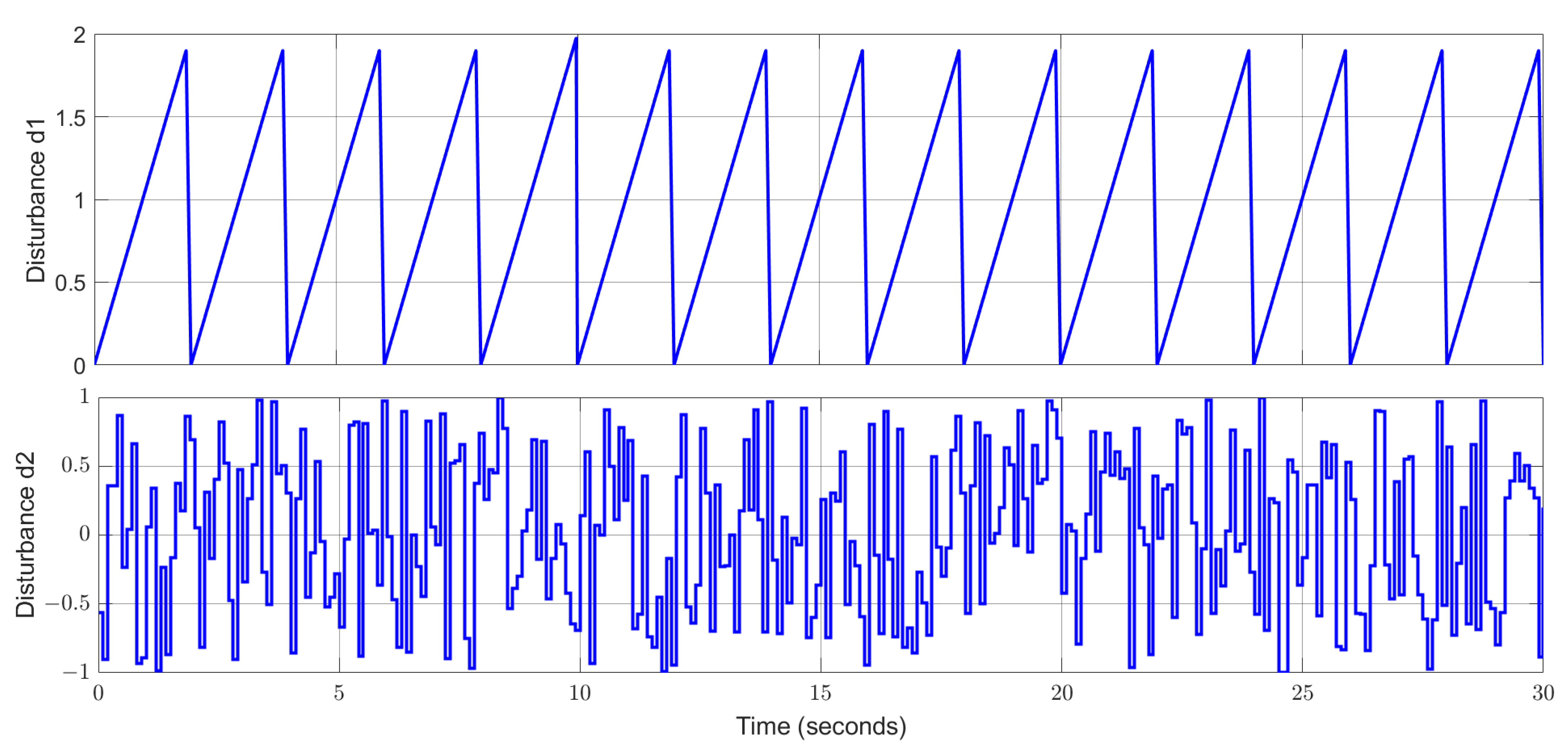
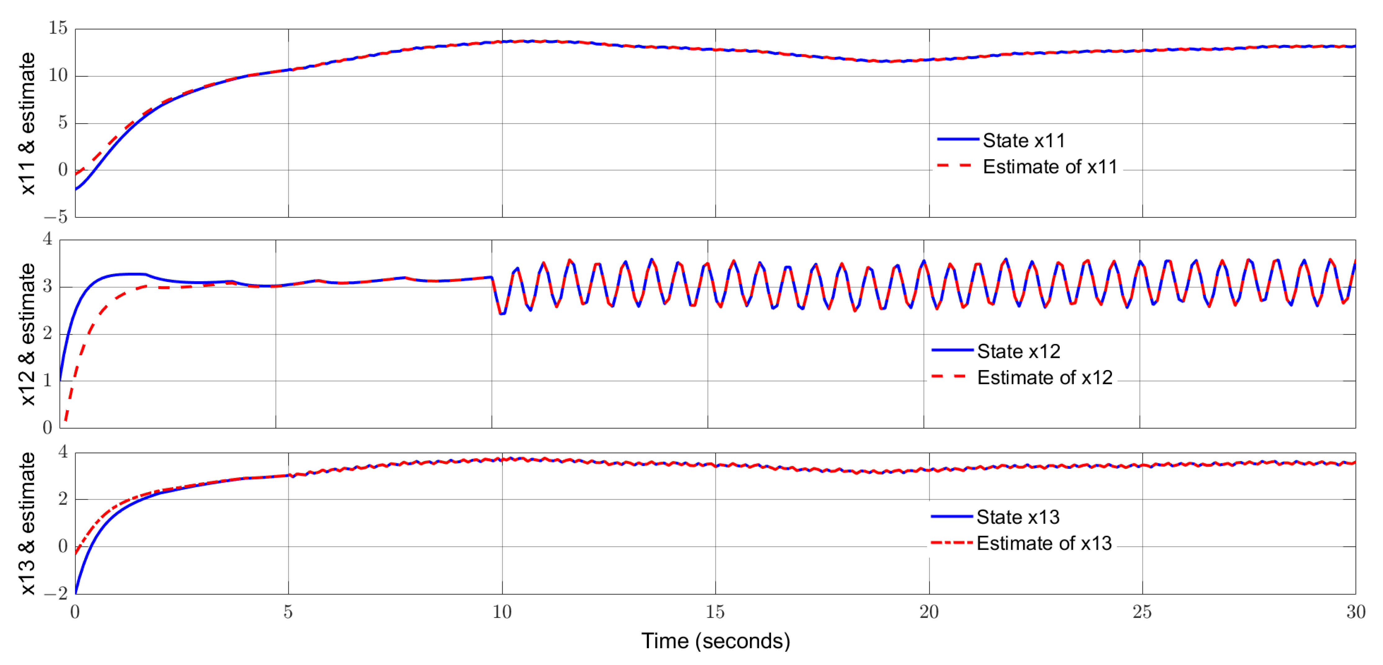
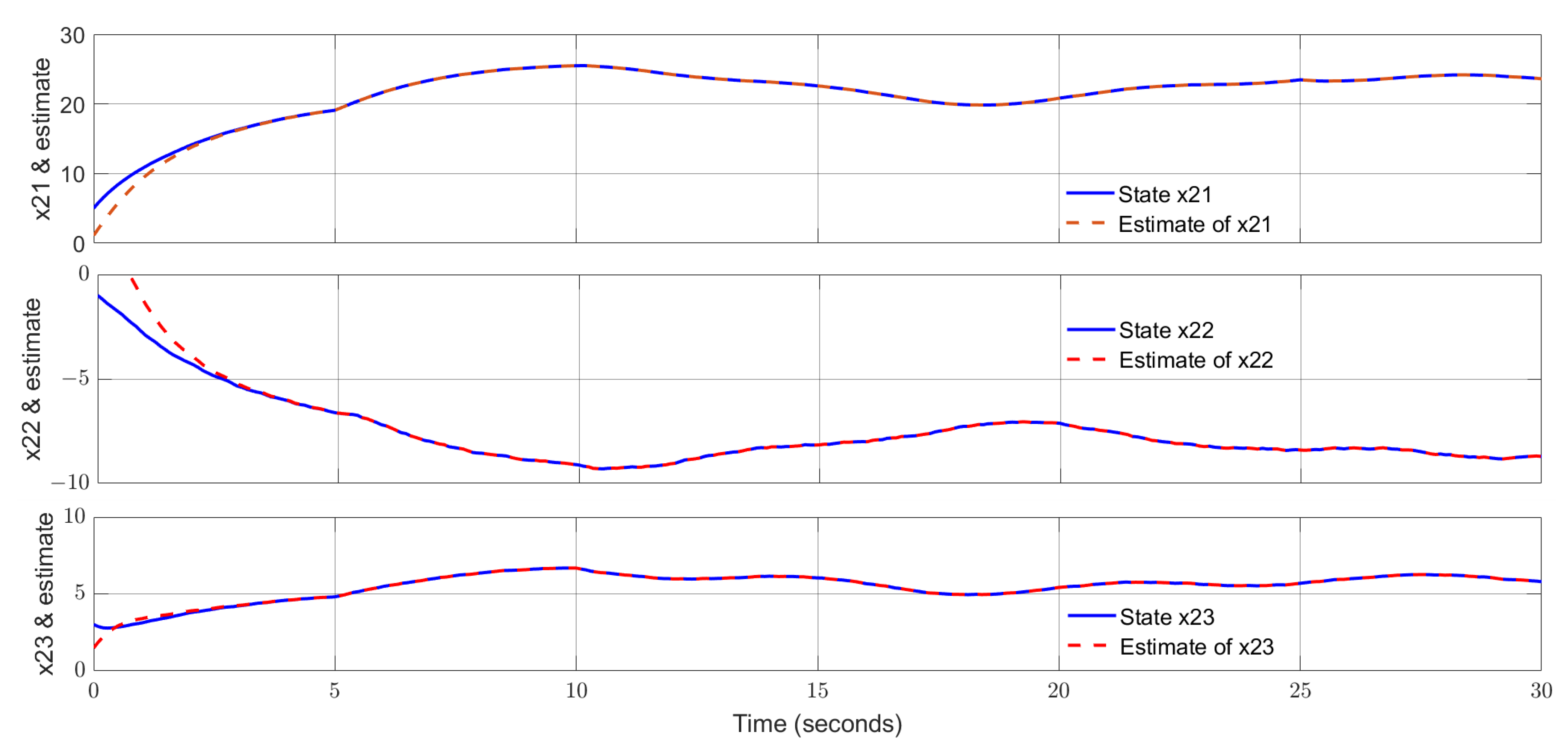
4. Simulation Study and Discussion

4.1. Simulation Study

Consider the interconnected system in the form of (1), where the parameters are given as follows:
A 1 = 1.5 0 2.5 0 1.5 1 0.1 0 2 ,   B 1 = E 1 = 1       0 0       1 1       0 , C 1 = 1           0           0 0           1           0 0           0           1 ,   D 1 = F 1 =     1         0 1         0 1       1 , B d 1 = 0.13 0.2 0.1 ,   H 12 = 0.3 0.1 0.1 0.1 0 0.1 0.2 0.2 0.1 , g x 1 , t = 0.5 s i n x 12 t ,   B g 1 = 0 0 1 , x 1 t = x 11 t x 12 t x 13 t , A 2 = 1                     0                     3   1       3     0.5     0.4                 0             2     ,   B 2 = E 2 = 0       1 1       0 1       0 , C 2 = 1           0           0 0           1           0 0           0           1 ,   D 2 = F 2 =     1         0 1       0     0         1 , B d 2 = 0.15 0.4 0.2 ,   H 21 = 0 0.1 0.1 0.1 0 0.1 0 0.2 0 , g x 2 , t = 0.4 s i n x 23 t , B g 2 = 0 0 1 ,   x 2 t = x 21 t x 22 t x 23 t .
The input signals are u 1 t = u 2 t = 2 5 . In this section, MATLAB/Simulink [58] is used as a simulator to simulate the dynamic responses of the interconnected system and the proposed observer. The unknown input disturbances are depicted by Figure 1.
Notice that the Lipschitz constants are set to γ 1 = 0.5 and γ 2 = 0.4 ,   and select ε 1 = ε 2 = 10 ,   o = 2 , and r = 1.5 . By solving (14), (50), and (51), the observer gains can be obtained as follows:
L 1 = 0.9921 0.1276 0.6147 0.5480 1.4119 0.6160 0.5479 0.4188 0.5847 0.5495 0.1271 0.6157 0.0014 0.5477 1.5089 , L 2 = 0.9001 0.9833 1.5220 0.6467 0.5629 1.5204 1.3058 0.8698 0.8615 0.6434 0.9799 1.5207 1.3039 0.8685 2.4018 , K 1 = 1.9012 0.4633 1.2943 0.3562 1.0087 0.3611 2.0027 1.2931 0.3583 1.0099 0.0066   0.0357 1.8699 0.0168 0.2817 0.3596 0.4639 1.2934 1.8982 1.0096 0.3559 0.4978 0.9634   0.3405 0.8119 , K 2 = 1.3546 0.1650 0.7962 0.1895 0.7947 0.1921 1.3810 0.7979 0.1889 0.7931 0.1785 0.2211 2.0476 0.2004 0.4979 0.1889 0.1616 0.7974 1.3505 0.7935 0.1766 0.2224 0.5073 0.2009 2.0381 , J 1 =   0.8264 0.6144 0.3940 0.8265 0.6143 0.3939   0.0808 0.3132 0.3030 0.8264 0.6144 0.3940 0.9071 0.3011 0.6970 , J 2 = 0.8512 1.1240 0.7273 0.8512 1.1239   0.7273 0.6380 0.0016 0.3636 0.8512 1.1240 0.7272 0.6380 0.0017 0.3636 , Φ 1 = 0.0921 0.2394   0.0995 , Φ 2 = 0.1349 0.2893 0.0398 .
In the simulation, the actuator faults in two subsystems are given as follows:
f 11 t = 5 s i n ( 20 t ) c o s ( 20 t ) , 5 t 30 0 ,                                           o t h e r w i s e f 12 t = 5 cos 10 t 10 , t 10 0 ,                                           o t h e r w i s e f 21 t = 0.5 ,                                           5 t < 10 0.5 sin t ,                                           t 10 0 ,                                           o t h e r w i s e f 22 t = 2 s i n 3 0.3 t ,         5 t 25 0 ,                                           o t h e r w i s e  
In the simulation, the initial states of the two subsystems are x 1 0 = 2   1 2 T and x 2 0 = 5 1   3 T , respectively. Select the parameter α 1 = α 2 = 50 .   The curves of the states and their estimates for subsystem 1 are shown by Figure 2. The trajectories of the additive actuator faults and their estimates for subsystem 1 are displayed by Figure 3. The states and their estimates for subsystem 2 are exhibited by Figure 4, and the actuator faults and their estimates for subsystem 2 are drawn in Figure 5. From Figure 2, Figure 3, Figure 4 and Figure 5, one can notice that the estimated signals can track the real signals well. More specifically, the states of two subsystems are reconstructed excellently and the additive actuator faults are successfully estimated with high accuracy. The impacts from the uncertainties on the estimated curves are alleviated successfully, showing a strong robustness of the proposed observer. Moreover, both high-frequency and low-frequency fault signals are reconstructed excellently, indicating a wide applicability of the proposed estimator.
Remark 10.
In the proposed fault estimation approach, the fault signal is incorporated into an extended state vector which is estimated by using an extended state observer. As a result, there are no constraints on the types of faults considered in principle. From the simulation studies, one can conclude that fault-free signals (zero signals), abrupt faults (step signals), and sinusoidal signals (low- and high-frequency signals) can be well reconstructed.

4.2. Discussion for Comparison

For the comparison, Table 1 is provided to summarize the advantages and limits of the existing approaches in the literature and the proposed approach in this paper. One can perceive that the proposed approach is a unique approach for handling actuator faults for interconnected systems with a direct feedthrough input term and is capable of reconstructing both low-frequency and high-frequency fault signals and has excellent robustness by removing the impact from uncertain process disturbances. As a result, the proposed approaches outperform many of the existing actuator fault estimation techniques for interconnected systems.

5. Conclusions

In this study, for interconnected systems with direct feedthrough terms, a nonlinear observer has been proposed. An augmented system approach has been used to achieve a simultaneous estimation of system states and actuator faults. An additional control term in the observer can effectively remove the influence from unknown process uncertainties, ensuring a robust estimation performance. The simulation studies have demonstrated an excellent tracking performance of the proposed estimation technique.
The proposed fault estimation approaches have potential in applications to various engineering systems such smart grids, multi-robot collaboration, etc. Moreover, the proposed fault estimation approach is anticipated to be extended to more complex scenarios, such as interconnected systems with high nonlinearities, and interconnected systems with communication delays, in the future.

Author Contributions

Conceptualization, Z.-W.G.; writing—original draft preparation, L.F. and Z.-W.G.; writing—revision, Z.-W.G.; supervision, Z.-W.G.; project administration, Z.-W.G. and Y.L.; software, L.F., Z.-W.G., and Y.L.; validation, L.F. and Z.-W.G.; formal analysis, L.F. and Z.-W.G. All authors have read and agreed to the published version of the manuscript.

Funding

This research was fund by the National Nature Foundation of China (62473095), NNSFC Innovative Talents Program, Featured Research Team Fund from the Fundamental Research Grant of Heilongjiang Province (2023TSTD-03), and Starting Research Fund for Talents in Northeast Petroleum University.

Data Availability Statement

No new data were created in this study.

Conflicts of Interest

The authors declare that there are no competing financial interests or personal relationships that could have appeared to influence the work reported in this paper.

References

  1. Gao, Z.-W.; Huang, Q.; Liu, Y. Fault reconstruction approach for saturated dynamic systems using adaptive estimation and optimization. ISA Trans. 2025, in press. [Google Scholar] [CrossRef] [PubMed]
  2. Chen, Y.; Zeng, X.; Huang, H. Fault diagnosis of rolling bearings based on adaptive denoising residual network. Processes 2025, 13, 151. [Google Scholar] [CrossRef]
  3. Dao, F.; Zeng, Y.; Qian, J. Fault diagnosis of hydro-turbine via the incorporation of Bayesian algorithm optimized CNN-LSTM neural network. Energy 2024, 290, 130326. [Google Scholar] [CrossRef]
  4. Wang, Z.; Gao, Y.; Yu, J.; Tian, L.; Yin, C. Data-driven fault diagnosis of PEMFC water management with segmented cell and deep learning technologies. Int. J. Hydrogen Energy 2024, 67, 715–727. [Google Scholar] [CrossRef]
  5. Li, S.; Zhang, C.; Du, J.; Cong, X.; Zhang, L.; Jiang, Y.; Wang, L. Fault diagnosis for lithium-ion batteries in electric vehicles based on signal decomposition and two-dimensional feature clustering. Green Energy Intell. Transp. 2022, 1, 100009. [Google Scholar] [CrossRef]
  6. Cao, Y.; Tang, J.; Shi, S.; Cai, D.; Zhang, L.; Xiong, P. Fault diagnosis techniques for electrical distribution network based on artificial intelligence and signal processing: A review. Processes 2025, 13, 48. [Google Scholar] [CrossRef]
  7. Zhang, P.; Lu, D. A Survey of condition monitoring and fault diagnosis toward integrated O&M for wind turbines. Energies 2019, 12, 2801. [Google Scholar] [CrossRef]
  8. Hong, Y.; Pula, R. Methods of photovoltaic fault detection and classification: A review. Energy Rep. 2002, 8, 5898–5929. [Google Scholar] [CrossRef]
  9. Ragab, A.; EL-Koujok Poulin, B.; Amazouz, M.; Yacout, S. Fault diagnosis in industrial chemical processes using interpretable patterns based on logical analysis of data. Expert Syst. Appl. 2018, 95, 368–383. [Google Scholar] [CrossRef]
  10. Xie, S.; Tan, H.; Yang, C.; Yan, H. A review of fault diagnosis methods for key systems of the high-speed train. Appl. Sci. 2023, 13, 4790. [Google Scholar] [CrossRef]
  11. Xu, X.; Yan, X.; Yang, K.; Zhao, J.; Sheng, C.; Yuan, C. Review of condition monitoring and fault diagnosis for marine power systems. Transp. Saf. Environ. 2021, 3, 85–102. [Google Scholar] [CrossRef]
  12. Zhao, D.; Fu, F.; Wang, D.; Shi, Y. Fault diagnosability evaluation for interconnected large-scale cyber–physical systems. Automatica 2025, 173, 112090. [Google Scholar] [CrossRef]
  13. Antonelli, G. Interconnected dynamic systems: An overview on distributed control. IEEE Control Syst. Mag. 2013, 33, 76–88. [Google Scholar]
  14. Wang, J.; Butcher, A. Decentralized estimation of spacecraft relative motion using consensus extended Kalman filter. In Proceedings of the Space Flight Mechanics Meeting, Kissimmee, FL, USA, 8–12 January 2018. [Google Scholar] [CrossRef]
  15. Zhang, J.; Ding, S.; Zhang, D.; Li, L. Distributed fault detection for large-scale interconnected systems. IET Control Theory Appl. 2023, 18, 2347–2357. [Google Scholar] [CrossRef]
  16. Boem, F.; Carli, R.; Farina, M.; Ferrari-Trecate, G.; Parisini, T. Distributed fault detection for interconnected large-scale systems: A scalable plug & play approach. IEEE Trans. Control Netw. Syst. 2019, 6, 800–811. [Google Scholar]
  17. Baroumand, S.; Zaman, A.; Mihaylova, L.S. Attack detection and fault-tolerant control of interconnected cyber-physical systems against simultaneous replayed time-delay and false-data injection attacks. IET Control Theory Appl. 2023, 17, 527–541. [Google Scholar] [CrossRef]
  18. Boem, F.; Gallo, A.J.; Raimondo, D.M.; Parisini, T. Distributed fault-tolerant control of large-scale systems: An active fault diagnosis approach. IEEE Trans. Control Netw. Syst. 2020, 7, 288–301. [Google Scholar] [CrossRef]
  19. Qin, L.; He, X.; Yan, R.; Deng, R.; Zhou, D. Distributed sensor fault diagnosis for a formation of multi-vehicle systems. J. Frankl. Inst. 2019, 356, 791–818. [Google Scholar] [CrossRef]
  20. Gao, Z.; Ho, D. Proportional multiple-integral observer design for descriptor systems with measurement output disturbances. IEE Control Theory Appl. 2004, 151, 279–288. [Google Scholar] [CrossRef]
  21. Khedher, A.; Benothman, K.; Maquin, D.; Benrejeb, M. State and sensor faults estimation via a proportional integral observer. In Proceedings of the 6th International Multi-Conference on Systems, Signals and Devices, Djerba, Tunisia, 23–26 March 2009. [Google Scholar]
  22. Gao, Z.; Ding, S.; Ma, Y. Robust fault estimation approach and its application in vehicle lateral dynamic systems. Optim. Control Appl. Methods 2007, 28, 143–156. [Google Scholar] [CrossRef]
  23. Gao, Z.; Wang, H. Descriptor observer approaches for multivariable systems with measurement noises and application in fault detection and diagnosis. Syst. Control Lett. 2006, 55, 304–313. [Google Scholar] [CrossRef]
  24. Zhang, J.; Swain, A.; Nguang, S.; Nasiri, A. Estimation of actuator and sensor faults for nonlinear systems using a descriptor system approach. In Proceedings of the 53rd IEEE Conference on Decision and Control, Los Angeles, CA, USA, 15–17 December 2014. [Google Scholar]
  25. Gao, Z. Estimation and compensation for Lipschitz nonlinear discrete-time systems subjected to unknown measurement delays. IEEE Trans. Ind. Electron. 2015, 62, 5950–5961. [Google Scholar] [CrossRef]
  26. Defoort, M.; Veluvolu, K.C.; Rath, J.; Djemai, M. Adaptive sensor and actuator fault estimation for a class of uncertain Lipschitz nonlinear systems. Int. J. Adapt. Control Signal Process. 2016, 30, 271–283. [Google Scholar] [CrossRef]
  27. Huang, Q.; Gao, Z.-W.; Liu, Y. Sensor fault reconstruction using robustly adaptive unknown-input observers. Sensors 2024, 24, 3224. [Google Scholar] [CrossRef]
  28. Yang, J.; Zhu, F.; Wang, X.; Bu, X. Robust sliding-mode observer-based sensor fault estimation, actuator fault detection and isolation for uncertain nonlinear systems. Int. J. Control Autom. Syst. 2015, 13, 1037–1046. [Google Scholar] [CrossRef]
  29. Abdullah, A.; Qasem, O. Full-order reduced-order observers for linear parameter-varying systems with one-sided Lipschitz nonlinearities disturbances using parameter-dependent Lyapunov function. J. Frankl. Inst. 2019, 356, 5541–5572. [Google Scholar] [CrossRef]
  30. Wang, H.; Gao, Z.-W.; Liu, Y. Monitoring and reconstruction of actuator and sensor attacks for Lipschitz nonlinear dynamic systems using two types of augmented descriptor observers. Processes 2024, 12, 1383. [Google Scholar] [CrossRef]
  31. Gao, S.; Ma, G.; Guo, Y.; Zhang, W. Fast actuator and sensor fault estimation based on adaptive unknown input observer. ISA Trans. 2022, 129, 305–323. [Google Scholar] [CrossRef]
  32. Zhang, K.; Jiang, B.; Chen, M.; Yan, X. Distributed fault estimation and fault-tolerant control of interconnected systems. IEEE Trans. Cybern. 2021, 51, 1230–1240. [Google Scholar] [CrossRef]
  33. Mu, Y.; Zhang, H.; Yan, Y.; Xie, X. Distributed observer-based robust fault estimation design for discrete-time interconnected systems with disturbances. IEEE Trans. Cybern. 2023, 53, 6737–6747. [Google Scholar] [CrossRef]
  34. Song, X.; Man, J.; Song, S.; Ahn, C. Finite-time fault estimation and tolerant control for nonlinear interconnected distributed parameter systems with Markovian switching channels. IEEE Trans. Circuits Syst. I Regul. Pap. 2022, 69, 1347–1359. [Google Scholar] [CrossRef]
  35. Koo, G. Decentralized fuzzy fault estimation observer design for discrete-time nonlinear interconnected systems. Electronics 2024, 13, 1763. [Google Scholar] [CrossRef]
  36. Xia, J.; Jiang, B.; Zhang, K. Unknown observer-based distributed fault estimation of discrete-time nonlinear interconnected systems. Int. J. Control Autom. Syst. 2022, 20, 803–812. [Google Scholar] [CrossRef]
  37. Liang, D.; Yang, Y.; Li, R.; Zhao, Z. Plug-and-play robust distributed fault estimation for interconnected systems. IEEE Trans. Netw. Sci. Eng. 2022, 9, 3385–3395. [Google Scholar] [CrossRef]
  38. Zemouche, A.; Boutayeb, M. On LMI conditions to design observers for Lipschitz nonlinear systems. Automatica 2013, 49, 585–591. [Google Scholar] [CrossRef]
  39. Zhu, F.; Han, Z. A note on observers for Lipschitz nonlinear systems. IEEE Trans. Autom. Control 2002, 47, 1751–1754. [Google Scholar]
  40. Gao, Z.; Breikin, T.; Wang, H. High-gain estimator and fault-tolerant design with application to a gas turbine dynamic system. IEEE Trans. Control Syst. Technol. 2007, 15, 740–753. [Google Scholar] [CrossRef]
  41. Vanek, B.; Edelmayer, A.; Szabo, Z.; Bokor, J. Bridging the gap between theory and practice in LPV fault detection for flight control actuators. Control Eng. Pract. 2014, 31, 171–182. [Google Scholar] [CrossRef]
  42. Luenberger, D. Time-invariant descriptor systems. Automatica 1978, 14, 473–480. [Google Scholar] [CrossRef]
  43. Gao, Z. PD observer parametrization design for descriptor systems. J. Frankl. Inst. 2005, 342, 551–564. [Google Scholar] [CrossRef]
  44. Tripathi, M.; Moysis, L.; Gupta, M.; Fragulis, G.; Volos, C. Observer design for nonlinear descriptor systems: A survey on system nonlinearities. Circuits Syst. Signal Process. 2024, 43, 2853–2872. [Google Scholar] [CrossRef]
  45. Yang, J.; Zhu, F.; Zhang, W. Sliding-mode observers for nonlinear systems with unknown inputs and measurement noise. Int. J. Control Autom. Syst. 2013, 11, 903–910. [Google Scholar] [CrossRef]
  46. Chen, B.; Hu, G.; Ho, D.; Li, Y. Distributed estimation and control for discrete time-varying interconnected systems. IEEE Trans. Autom. Control 2021, 67, 2192–2207. [Google Scholar] [CrossRef]
  47. Corless, M.; Tu, J. State and input estimation for a class of uncertain systems. Automatica 1998, 34, 757–764. [Google Scholar] [CrossRef]
  48. Boyd, S.; El Ghaoui, L.; Feron, E.; Balakrishnan, V. Linear Matrix Inequalities in System and Control Theory; Society for Industrial and Applied Mathematics: Philadelphia, PA, USA, 1994; Volume 15. [Google Scholar]
  49. Boyd, S.; Balakrishnan, V.; Feron, E.; El Ghaoui, L. History of linear matrix inequalities in control theory. In Proceedings of the American Control Conference, Baltimore, MD, USA, 29 June–1 July 1994; pp. 31–34. [Google Scholar]
  50. Zhang, F. The Schur Complement and Its Applications; Springer: Berlin/Heidelberg, Germany, 2005. [Google Scholar]
  51. Ravat, A.; Dhawan, A.; Tiwari, M. LMI and YALMIP: Modelling and optimization toolbox in MATLAB. In Advances in VLSI, Communication, and Signal Processing; Springer: Singapore, 2020; pp. 507–515. [Google Scholar]
  52. Vito, D.; Kron, M.; Lafontaine, J.; Lovera, M. A Matlab toolbox for LMI-based analysis and synthesis of LPV/LFT self-scheduled H∞ control systems. In Proceedings of the IEEE International Symposium on Computer-Aided Control System Design, Yokohama, Japan, 8–10 September 2010; pp. 1397–1402. [Google Scholar]
  53. Nagy, S.; Petres, Z.; Baranyi, P. TP tool—A MATLAB toolbox for TP model transformation. In Proceedings of the 8th International Symposium of Hungarian Researchers on Computational Intelligence and Informatics, Budapest, Hungary, 15–17 November 2007; pp. 483–495. [Google Scholar]
  54. Weber, A.; Kuczmann, M. Extending the TPTool MATLAB toolbox with LMI based observer and disturbance rejection design. Results Control Optim. 2023, 13, 100302. [Google Scholar] [CrossRef]
  55. Utkin, V.; Poznyak, A.; Orlov, Y.; Polyakov, A. Road Map for Sliding Mode Control Design; Springer: Dordrecht, The Netherlands, 2020. [Google Scholar]
  56. Ding, S.; Park, J.; Chen, C. Second-order sliding mode controller design with output constraint. Automatica 2020, 112, 108704. [Google Scholar] [CrossRef]
  57. Lakshmanan, S.; Joo, Y. Decentralized observer-based integral sliding mode control design of large-scale interconnected systems its application to doubly fed induction generator-based wind farm model. Int. J. Robust Nonlinear Control 2023, 33, 5758–5774. [Google Scholar] [CrossRef]
  58. Get Started with Simulink; R2024b; Mathworks: Natick, MA, USA, 2024.
  59. Zhang, K.; Jiang, B.; Shi, P.; Pan, J. Distributed fault estimation design of interconnected systems with external disturbances. IET Control Theory Appl. 2019, 13, 377–386. [Google Scholar] [CrossRef]
  60. Xia, J.; Jiang, B.; Zhang, K. Fault diagnosis based on adaptive observer for interconnected systems. Control Eng. China 2020, 27, 1452–1457. [Google Scholar]
  61. Xia, J.; Jiang, B.; Zhang, K. Distributed fault estimation observer design for a class of interconnected nonlinear systems. Control Decis. 2019, 34, 727–734. [Google Scholar]
  62. Xu, S.; Dai, H.; Feng, L.; Chen, H.; Chai, Y.; Zheng, W. Fault estimation for switched interconnected nonlinear systems with external disturbances via variable weighted iterative learning. IEEE Trans. Circuits Syst.-II Express Brief 2023, 70, 2011–2015. [Google Scholar] [CrossRef]
Figure 1. Uncertain disturbances d1(t) and d2(t).
Processes 13 01283 g001
Figure 2. States of subsystem 1 and their estimates.
Processes 13 01283 g002
Figure 3. Actuator faults of subsystem 1 and their estimates.
Processes 13 01283 g003
Figure 4. States of subsystem 2 and their estimates.
Processes 13 01283 g004
Figure 5. Actuator faults of subsystem 2 and their estimates.
Processes 13 01283 g005
Table 1. Comparison between the proposed approach and other methods for fault estimation.
Fault Estimation Approaches for Interconnected SystemsAdvantagesLimits
Augmented Luenberger distributed observer [32] Actuator fault estimation can be achieved for low-frequency fault signals, and regional pole constraints are used to enhance the transient performance and ability to suppress the external disturbances.It is not applicable to estimate high-frequency actuator fault signals. Disturbance attenuation ability is relatively limited compared with disturbance decoupling techniques. Neither a nonlinear term nor direct feedthrough input term is considered in the interconnected system.
Descriptor distributed observer [33]Actuator fault estimation can be achieved for both low-frequency and high-frequency actuator fault signals, and regional pole constraints are used to enhance the transient performance and ability to suppress the external disturbances.Disturbance attenuation ability is relatively limited compared with disturbance decoupling techniques. Neither a nonlinear term nor direct feedthrough input term is considered in the interconnected system.
Fuzzy proportional and integral distributed observer [35]Actuator fault estimation can be achieved for low-frequency actuator fault signals with robustness against uncertainties. It is not applicable to reconstruct a very high-frequency actuator fault signal. Disturbance attenuation ability is relatively limited compared with disturbance decoupling techniques. No direct feedthrough input term is considered in the interconnected system.
Nonlinear augmented unknown input distributed observer [36]Actuator fault estimation can be achieved for low-frequency fault signals, and regional pole constraints are used to enhance the transient performance and ability to suppress the external disturbances.It is not applicable to reconstruct a very high-frequency actuator fault signal. No direct feedthrough input term is considered in interconnected systems.
Augmented unknown input distributed observer 1 [37]Robust actuator fault estimation can be achieved for low-frequency fault signals. Process disturbances are decoupled, and the measurement noise is attenuated by LMI optimization to ensure robustness. It is not applicable to reconstruct high-frequency actuator fault signals. Neither a nonlinear term nor direct feedthrough input term is considered in the interconnected system.
Augmented unknown input distributed observer 2 [59]Actuator fault estimation can be achieved particularly for low-frequency fault signals, and regional pole constraints are used to enhance the transient performance.It is not applicable to reconstruct a very high-frequency actuator fault signal. Neither a nonlinear term nor direct feedthrough input term is considered in the interconnected system.
Adaptive distributed observer [60]Actuator fault estimation can be achieved particularly for low-frequency fault signals. Robustness against uncertainty is not taken into account. The estimation capability for a high-frequency fault signal is questionable. Neither a nonlinear term nor direct feedthrough input term is considered in the interconnected system.
Nonlinear augmented Luenberger distributed observer [61]Actuator fault estimation can be achieved for low-frequency fault signals, and regional pole constraints are used to enhance the transient performance and ability to suppress the external disturbances.Disturbance attenuation ability is relatively limited compared with disturbance decoupling techniques. It is not applicable to reconstruct a high-frequency actuator fault signal. No direct feedthrough input term is considered in the interconnected system.
Nonlinear iterative learning disturbed observer [62]Actuator fault estimation can be achieved for both low-frequency and high-frequency fault signals. The robustness is discussed. Disturbance attenuation ability is relatively limited compared with disturbance decoupling technique. No direct feedthrough input term is considered in the interconnected system.
The proposed observer technique in this paperActuator fault estimation can be achieved for both low-frequency and high-frequency fault signals. The process disturbance is removed by using a nonlinear control term, and regional pole constraints are used to enhance the transient performance. Lipschitz nonlinear terms are considered. A direct feedthrough input term is included in the interconnected system.Further work needs to be done to extend the approach to more complex systems such as interconnected systems with high nonlinearities.
Disclaimer/Publisher’s Note: The statements, opinions and data contained in all publications are solely those of the individual author(s) and contributor(s) and not of MDPI and/or the editor(s). MDPI and/or the editor(s) disclaim responsibility for any injury to people or property resulting from any ideas, methods, instructions or products referred to in the content.

