Article

Three-Dimensional Carbon Nanotube-Coated Copper Mesh as a Current Collector for Graphite Anodes in High-Performance Lithium-Ion Batteries

1
Jiangxi Provincial Key Laboratory of Power Batteries & Energy Storage Materials, School of Materials Science and Engineering, Jiangxi University of Science and Technology, Ganzhou 341000, China
2
School of Physics and Electronics, Gannan Normal University, Ganzhou 341000, China
3
Yichun Lithium New Energy Industry Research Institute, Jiangxi University of Science and Technology, Yichun 336023, China
*
Authors to whom correspondence should be addressed.
Processes 2025, 13(4), 964; https://doi.org/10.3390/pr13040964
Submission received: 18 February 2025 / Revised: 17 March 2025 / Accepted: 21 March 2025 / Published: 24 March 2025
(This article belongs to the Section Materials Processes)

Abstract

:
Copper foil has been widely adopted as the anode current collector in commercial lithium-ion batteries (LIBs) due to its exceptional electrical conductivity, mechanical flexibility, and low cost. However, the smooth surface of copper foil often leads to active material delamination during cycling, resulting in accelerated capacity degradation. To address this limitation, this study developed a novel composite current collector featuring a high specific surface area and rough porous architecture through a dip-coating method. The fabrication process employs copper mesh as a structural skeleton, integrated with carbon nanotubes (CNTs) and polyvinylidene fluoride (PVDF) as functional fillers. Compared to conventional metallic copper foils, the composite current collector demonstrates superior interfacial wettability, enhanced adhesion strength, and reduced contact resistance. When paired with graphite as the active material, the graphite composite electrode exhibits outstanding cycling stability and rate capability. Specifically, the graphite composite electrode delivers a specific capacity of 297.9 mAh g−1 with 94.3% capacity retention after 200 cycles at 0.5 C, significantly outperforming the graphite–copper foil counterpart (238.3 mAh g−1, 81.2% retention). This work provides an innovative strategy for enhancing battery performance through the rational design of efficient and durable current collectors.

1. Introduction

Lithium-ion batteries (LIBs) serve as essential power sources for portable electronics, electric vehicles, and grid-scale energy storage systems. Characterized by high energy density, extended cycle life, and efficient charge–discharge capabilities, LIBs rely fundamentally on current collector performance [1,2]. The current collector, a critical LIB component, interfaces directly with electrode constituents (the active material, binder, and conductive agent), serving not only as an active material substrate but also functioning as an electron reservoir during electrochemical processes [3,4,5,6,7]. Key material parameters—including thickness, weight, and surface characteristics—directly affect internal resistance and overall battery performance [8,9,10,11]. Industrial applications predominantly utilize 2D metal foil current collectors; however, conventional fabrication methods present notable limitations [12,13,14,15,16]. The restricted interfacial contact area promotes active material detachment during cycling, leading to premature battery failure. Enhancing interfacial adhesion between these components therefore represents a critical pathway for improving energy density and cycle stability in LIB systems [17,18,19].
Enhancing the surface roughness of current collectors has been demonstrated as an effective strategy for improving interfacial adhesion with electrode materials [20,21,22,23,24,25,26,27,28]. Current methodologies primarily encompass the surface modification of two-dimensional planar current collectors, the construction of three-dimensional (3D) porous architectures, and coating methods [29,30,31,32,33,34,35,36,37]. The advancement of current collectors has been evolving toward composite structural designs, with coating-based modification strategies emerging as a promising approach. For instance, Kang et al. [25] successfully prepared the carbon-coated current collector by depositing a rough carbon layer on the surface of a planar copper foil by an electrical machining technique. The porous carbon coating on the surface of the composite current collector enhances the bond strength between the current collector and the electrode, improving the charge transfer rate and the reversible capacity of the graphite electrode. Ventrapragada et al. [29] developed a surfactant-free spray coating process to coat commercial cellulose-based paper with CNTs and prepared paper–CNT current collectors for LIBs. While existing optimization strategies enhance LIB performance through the increased architectural sophistication of current collector surfaces, these approaches remain constrained by intricate fabrication processes and prohibitive costs. Concurrently, the strategy of merely applying surface coatings on two-dimensional planar current collectors as a transitional approach toward three-dimensional architectures fails to fundamentally resolve critical issues, such as cycling life deterioration caused by active material detachment. The critical merit of 3D designs lies in their capacity to effectively constrain the volume expansion of active materials, which should be encapsulated within the current collector matrix rather than superficially adhered to its surface.
Herein, we present a novel composite current collector comprising a copper mesh “skeleton” integrated with a CNT “epidermal” layer, fabricated via a facile yet effective dip-coating method. This design preserves the intrinsic architecture of the copper mesh while introducing a CNT-based conductive film, which spontaneously generates a regular rough and porous surface due to its inherent structural characteristics. Compared to the copper foil, this unique micro-nano hierarchical structure significantly enhances the specific surface area of the current collector, effectively mitigating active material delamination. Interfacial shear testing and post-cycling electrode morphological characterization conclusively demonstrate improved adhesion between the components and enhanced structural stability of the electrode. The modified current collector architecture contributes to the superior cycling longevity and rate performance of LIBs. This study substantiates the efficacy of CNT-coated copper mesh in LIB applications, providing innovative concepts and critical insights for developing cost-effective, stable, and high-performance current collectors.

2. Experimental

2.1. Sample Preparation

The conductive slurry comprises carbon nanotubes (CNTs) and N-methylpyrrolidone (NMP, Tianjin Damao Chemical Reagent Factory, Tianjin, China) and is prepared in-house with a mass ratio of 4:96. The requisite quantities of conductive slurry and NMP were separately weighed on an electronic balance. The NMP was then poured into the beaker containing the conductive slurry, and the conductive slurry was diluted from ω (4%) to ω (2%) using NMP as a solvent. A specific quantity of polyvinylidene fluoride (PVDF, Fluorite Material Technology Co., Ltd., Tianjin, China) was weighed and combined with it in a manner that ensured a 4:1 ratio of CNTs to PVDF. The beaker was sealed with cling film and placed on a magnetic stirrer for a period of six hours to ensure the thorough homogenization of the slurry. A piece of copper mesh (Jinanjia New Materials Co., Ltd., Kunshan, China) measuring 6 × 6 cm2 was cut. The copper mesh was immersed in the prepared conductive paste for a period of time, after which it was dried in a drying oven set to 120 °C for 10 h. This step was repeated two or three times to obtain the composite collector. The calculated surface densities of CNTs and PVDF in the composite current collector were found to be 1.15 mg cm−2 and 0.29 mg cm−2, respectively.
The active material (graphite, Shenzhen Kejing Zhida Technology Co., Ltd., Shenzhen, China), carbon black (SP, Shanghai Boochem Co., Ltd., Shanghai, China), and polyvinylidene fluoride (PVDF) were weighed in a mass ratio of 8:1:1, respectively. N-methylpyrrolidone (NMP) was employed as a solvent to dissolve the electrode material until a homogeneous solution was obtained. The mixed slurry was coated on the copper foil (Guangdong Jia Yuan Technology Shares Co., Ltd., Meizhou, China), copper mesh, and composite current collector, respectively. The electrode piece was then obtained after drying in a vacuum drying oven at 120 °C for 6 h. The prepared pole pieces were treated by roller pressing and cut into disks with a diameter of 14 mm. The loading of graphite in the electrode piece was calculated to be 9.58 mg cm−2. They were then dried in a vacuum drying oven at 65 °C for 24 h. The CR2032 coin half-cell was assembled in a high-purity argon glove box (Shanghai Micronova Electromechanical Technology Co., Ltd., Shanghai, China) (with an oxygen concentration of less than 0.01 ppm and a water concentration of less than 0.01 ppm) using a lithium wafer as the counter electrode, Celgard 2400 (Celgard, LLC, Charlotte, NC, USA) as the separator, and a system of 1 mol/L LiPF6/(EC:DEC) (1:1 by volume) as the electrolyte (Suzhou Duoduo Reagent Co., Ltd., Suzhou, China). The electrochemical performance of the material is evaluated through a series of tests, including constant-current charge–discharge cycling (voltage range 0.03–3.0 V), cyclic voltammetry (CV), and electrochemical impedance spectroscopy (EIS).

2.2. Characterization and Electrochemical Testing

The surface or cross-section of the current collectors and electrodes was characterized using a Gemini 300 scanning electron (Carl Zeiss AG, Oberkochen, Germany) microscope and an electron dispersive energy spectrometer (SEM-EDS) from ZEISS, Germany. An X-ray diffractometer (D8 ADVANCE, Bruker AXS GmbH, Karlsruhe, Germany) was used to analyze the physical phase of the current collectors and electrodes, with diffraction angles ranging from 10° to 80°. The microstructure and surface roughness were characterized by atomic force microscopy (Dimension ICON atomic force microscope, Bruker Nano Surfaces, Billerica, MA, USA). The N2 adsorption/desorption isotherms were obtained by an Isorb-HP2 analyzer (Quantachrome, Quantachrome Instruments, Boynton Beach, FL, USA). A contact angle analysis, conducted using a JY-82B video contact angle tester (Dingsheng Testing Machine Testing Equipment Co., Ltd., Chengde, China), confirmed that NMP exhibited superior wettability on the surface of the composite current collector in comparison to the copper foil tested. The interfacial shear stress tests of the graphite electrodes with the composite current collector and the copper foil were conducted using a MTS E43.104 universal testing machine (MTS Systems Corporation, Eden Prairie, MN, USA) at a strain rate of 1 mm min−1. The samples were cut into rectangles of 10 mm × 10 mm and affixed to both sides of the grip with two pieces of 3M tape. A constant current charge/discharge cycle test was conducted using a Neware battery tester (BTS-5 V/10 mA) (Neware Technology Limited, Shenzhen, China) on the battery that had been left to stand for 12 h, with a voltage range of 0.03–3 V. Cyclic voltammetry (CV) tests were performed using an electrochemical workstation (CHI660E). The reversibility of the electrochemical reactions was verified by the CV curves obtained, and the electrochemical reactions and phase changes that occurred were analyzed based on the potentials of the redox peaks (sweep rate of 0.1 mV s−1, voltage range 0.03–3 V). An electrochemical AC impedance test (EIS) was conducted using an electrochemical workstation (CHI660E, Shanghai Chenhua Instrument Co., Ltd., Shanghai, China) with a test frequency range of 0.01 Hz to 100 kHz. The Li+ chemical diffusion coefficients (DLi+) were determined using the GITT, which was performed at 0.1 C for 10 min of charging, followed by 40 min of relaxation between 0.03 and 2.0 V.

3. Results and Discussion

3.1. Characterization of the Current Collectors and Electrodes

X-ray diffraction (XRD) analysis was used to determine the physical phase of different current collectors and electrodes, as shown in Figure S1. Three types of current collector exhibit the Cu diffraction peak, with differing intensities observed between the copper foil and the copper mesh (Figure S1a). This is attributed to the preferential orientation of the copper wires during the drawing process [38]. Additionally, a broad peak of CNT diffraction at 25° is observed in the composite current collector. The characteristic diffraction peak of the graphite (002) crystal plane is observed at 26.5° (Figure S1b). The use of different current collector substrates has been observed to result in notable alterations in the intensity of the (002) characteristic peak in graphite. The insertion/extraction process of lithium ions between graphite layers may be influenced by the presence of different intensities of (002), which could potentially alter the diffusion kinetics during lithium storage. Figure 1a,b illustrate the scanning electron microscope (SEM) images of the surface of current collectors. The pristine copper mesh exhibits a regular woven mesh structure, with an aperture and copper wire diameter of approximately 75 μm and 50 μm, respectively (Figure S2a,c). The composite current collector presents a regular micron-scale rough surface, evidently enhanced by the inherent structure of the copper mesh (Figure 1b). Furthermore, the conductive film was observed to remain intact despite the stresses induced during the drying process. The CNTs displayed a compact stacking pattern, suggesting that the conductive film of the composite current collector is dense and possesses good adhesion. As shown in Figure S3, the surface of the composite current collector is characterized by an interconnected conductive network architecture, which can be observed at the nanoscale level. This nanoscale porous structure has the potential to enhance the specific surface area of the composite current collector. The distribution of the three elements, C, Cu, and F, in the sample is uniform, and there is no evidence of localized agglomeration. This indicates that the conductive film is uniformly encapsulated and filled in the copper mesh. The surface of the composite current collector contains traces of element F and a small amount of element Cu, which suggests that the conductive film has good coverage and adhesion to the copper mesh [39]. The morphology and roughness of the copper foil and composite current collector were further investigated using AFM, as shown in Figure 1c,d. The surface of the copper foil is relatively smooth (Figure 1a), whereas that of the composite current collector is rough. Based on the AFM analysis, the surface roughness of the copper foil and composite collector was measured to be 36.2 nm and 155 nm, respectively.
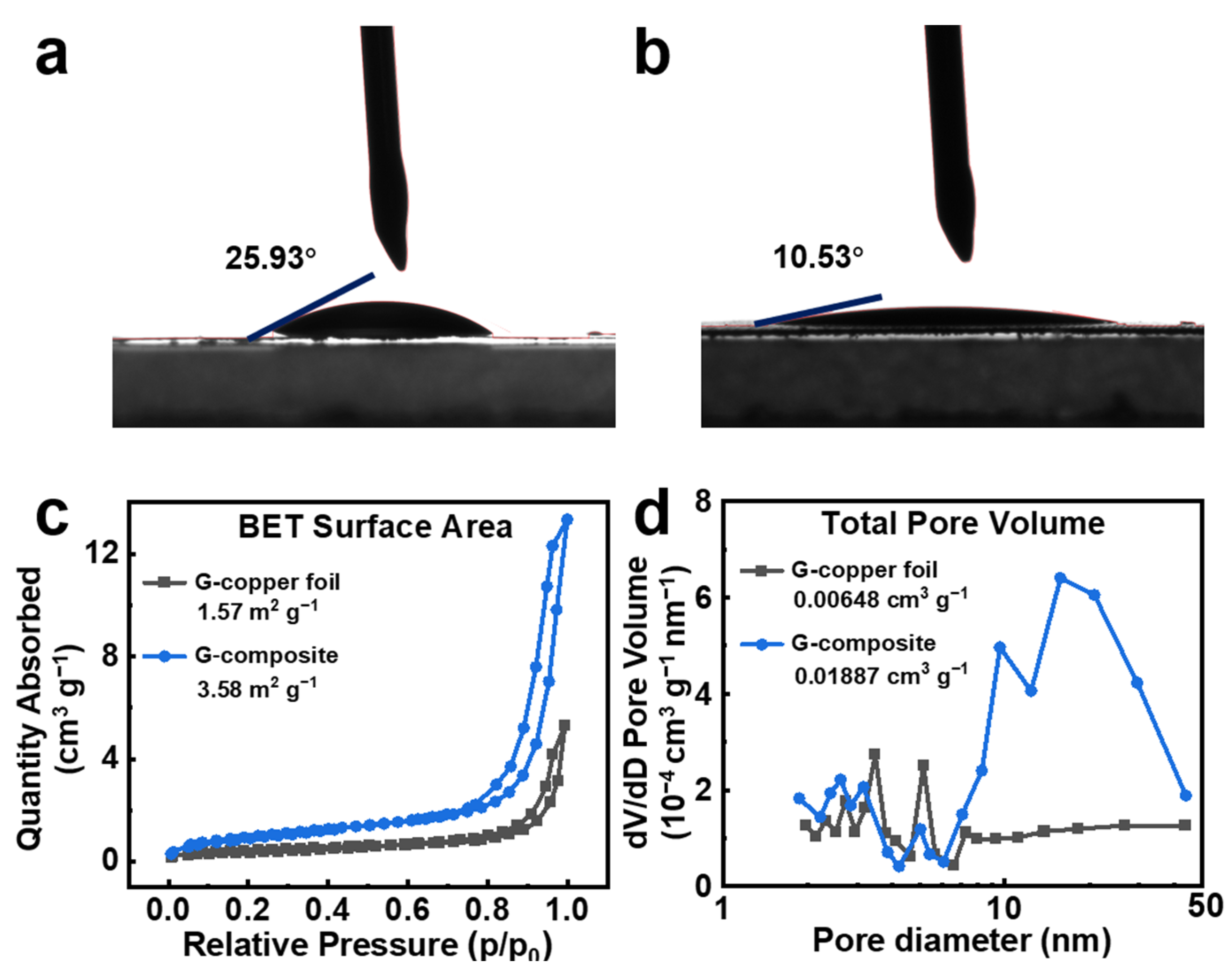
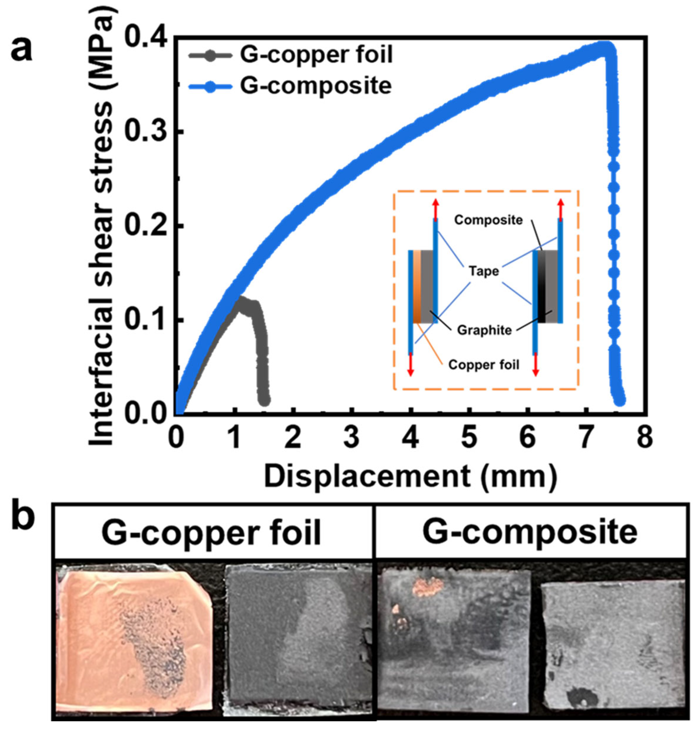
In order to assess the wettability of the copper foil and the composite current collector, a contact angle test was performed using NMP, as illustrated in Figure 2a,b. The degree of wettability directly correlates with the strength of adhesion. The contact angle of the composite current collector is approximately 10.53° (Figure 2b), which is considerably lower than that of 25.93°, as observed for the copper foil (Figure 2a). This is attributed to the reduced surface tension at the interface between the NMP and the composite current collector. The larger specific surface area and porosity result in a smaller contact angle of the composite collector, which indicates that the composite collector exhibits superior wettability of the binder solution compared to copper foil [40]. To further analyze the structure, a N2 adsorption/desorption test was performed. For the sake of simplicity, the following references will be made to the graphite–copper foil electrode, graphite–copper mesh electrode, and graphite composite current collector electrode: G-copper foil, G-copper mesh, and G-composite, respectively, in the following text. As illustrated in Figure 2c, the specific surface areas of G-copper foil and G-composite, as determined by the Brunauer–Emmett–Teller (BET) test, were 1.57 m2 g−1 and 3.58 m2 g−1, respectively. The G-composite displays a type IV hysteresis loop isotherm, indicative of the porous nature of the sample [41]. As illustrated in Figure 2d, the G-composite displays a distinctive mesoporous distribution when compared to the G-copper foil. This is characterized by a concentrated pore size distribution within the range of 10–50 nm. The presence of pores in the electrode increases the contact area with the electrolyte, thereby enhancing the lithium-ion diffusion coefficient [42]. The characterization of the interface adhesion of G-composite and G-copper foil was determined by interfacial shear tests (Figure 3a). The shear strength of G-composite was measured to be ~0.39 MPa, which is nearly 3.3 times the interfacial adhesion performance than the G-copper foil (~0.118 MPa). As illustrated in Figure 3b, the final stage of the test revealed that the majority of the graphite had been removed from the copper foil. In contrast, some graphite remained in the composite current collector, which provides direct evidence. The results of the interfacial shear test align with the contact angle measurements, thereby substantiating the assertion that the graphite interface with the composite current collector exhibits optimal wettability and robust adhesion. The excellent interfacial properties ensure that the composite collector and the graphite layer maintain tight contact, even when subjected to volume changes during high current and long cycling.

3.2. Electrochemical Testing of the Electrodes

To demonstrate the competitiveness of the composite current collector as a current collector for LIBs, we compared the electrochemical performance of graphite electrodes prepared on the copper foil, copper mesh, and composite current collector. Figure S4 shows the first three constant-current charge/discharge curves of copper foil, copper mesh and composite current collector electrodes, respectively, at a rate of 0.1 C. Figure 4a shows the first charge/discharge curves of the three electrodes. The first discharge and charge specific capacities of the G-composite were 376.7 mAh g−1 and 319.8 mAh g−1, respectively, and the first coulombic efficiency was calculated to be 84.9%, which exhibited a relatively lower coulombic efficiency (CE). The higher irreversible capacity is associated with the incorporation of CNTs and the enhanced contact area with the electrolyte due to the augmented surface roughness, which will lead to the formation of more solid electrolyte interface (SEI) and other side reactions [43]. In terms of rate performance, the G-composite exhibits excellent rate behavior, showing discharge specific capacities of 302.1 mAh g−1 and 262.5 mAh g−1 at 1 C and 2 C rates, respectively, followed by the G-copper mesh and G-copper foil (Figure 4b). As the current increased, the three electrodes demonstrated a progressive divergence in performance throughout the rate test. In comparison to the G-copper foil, the incorporation of a porous structure within the three-dimensional porous G-composite with a high specific surface area enhances the contact area with the electrolyte. The interstitial vacancies within the 3D CNT-coated copper mesh structure serve as wettable sites for electrode slurries, while providing additional diffusion pathways that facilitate their penetration into the intertubular voids of carbon nanotube bundles. This configuration enables the establishment of a continuous ion transport network while effectively mitigating ionic concentration polarization (Figure S3). Furthermore, the surface vacancies contribute to enhanced electronic conduction pathways by optimizing electron mobility, thereby significantly reducing electrochemical polarization [37,44]. This synergistic mechanism concurrently improves both the ionic and electronic transport properties within the composite electrode architecture [45]. The cycling performance at 0.5 C demonstrates that the graphite electrode on the composite current collector exhibits a superior cycling capacity (Figure 4c). After 200 cycles, the composite current collector, copper foil, and copper mesh electrodes exhibited specific discharge capacities of 297.9 mAh g−1, 238.3 mAh g−1, and 203.8 mAh g−1, respectively (the G-composite demonstrated a capacity retention of 94.3%). Figure S5 shows the cyclic voltammetry curves of the three electrodes with potential ranges and scan rates of 0.03–3 V and 0.1 mV s−1, respectively. The reduction peaks observed at 1.0–1.5 V were all present in the initial negative scan and absent in subsequent cycles. This phenomenon may be attributed to electrolyte decomposition and SEI formation. The cyclic voltammetry curve of the G-composite demonstrates excellent curve overlap and reversible capacity with high electrochemical performance, as evidenced by a superior performance compared to G-copper foil and G-copper mesh.
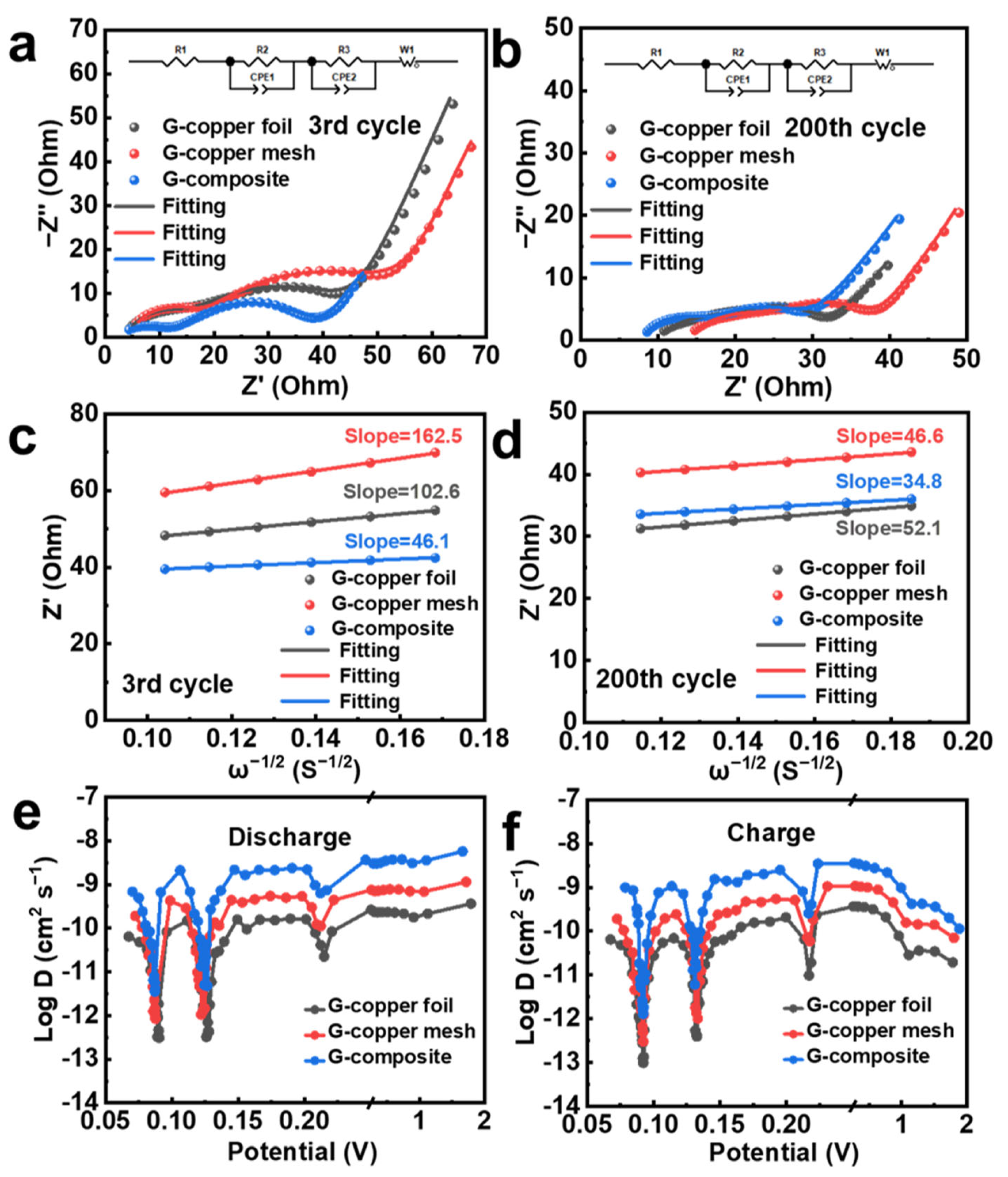
Electrochemical impedance spectroscopy (EIS) was employed to assess the kinetics of the electrochemical reaction [46]. The curve was fitted using an equivalent circuit in order to obtain the corresponding impedance values, which are presented in Table S1. According to Figure 5c, the lithium-ion diffusion coefficients of the G-copper foil, G-copper mesh, and G-composite were calculated to be 6.67 × 10⁻¹² cm2 s−1, 4.21 × 10⁻¹² cm2 s−1, and 1.48 × 10⁻¹¹ cm2 s−1, respectively, following the completion of the third cycle. This suggests that the G-composite exhibits a superior lithium-ion diffusion rate. It is noteworthy that the Rsf of the G-composite undergoes minimal alteration after 200 cycles in Figure 5b. This indicates that the SEI of the G-composite remained essentially stable throughout the cycling process [47]. The diffusion kinetics of different graphite electrodes in lithium storage were analyzed using the galvanostatic intermittent titration technique (GITT) [48]. Figure S6 illustrates the GITT curves of various graphite electrodes for the specified cycle, within a voltage range of 0.03 to 2 V. Figure 5e,f illustrate the DLi+ values obtained during the charging and discharging processes for the G-copper foil, G-copper mesh, and G-composite. All three samples demonstrate a consistent pattern of behavior during the charging and discharging processes. During discharge, the level of DLi+ in the G-composite reached 10−9 cm2 s−1 before 0.25 V, decreased to 10−12 cm2 s−1 around 0.12 and 0.08 V, and returned to 10−9 cm2 s−1 at 0.06 V (Figure 5e). The G-composite exhibited higher DLi+ values at any voltage, suggesting that the dual action of the mesh structure of the copper mesh and the conductive network in the carbon nanotubes (Figure S3) facilitates the lithiation and delithiation kinetics of Li+ in the electrodes.

3.3. Structural Characterization of the Electrodes Before and After Cycling

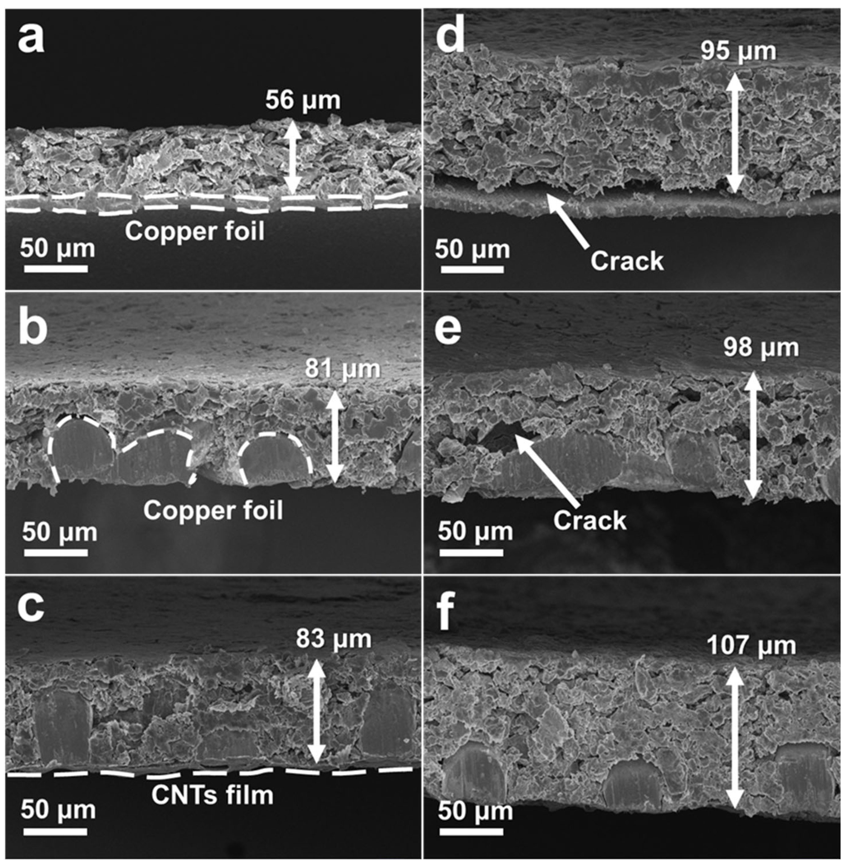
The surface and cross-sectional morphology of the electrodes was observed by scanning electron microscopy (SEM) before and after the cycling process. Following 200 cycles, as illustrated in Figure 6a,b,d,e, disparate degrees of separation between the active material and the current collector were observed for both the G-copper foil and the G-copper mesh. The lack of spatial support for the active material in the through-hole of the copper mesh (Figure S7b,e) results in the active material being susceptible to cracking and loosening from the inside to the outside. This suggests that the copper mesh is unable to effectively accommodate the volume changes in the active material during the charging and discharging. The interfacial contact between the active material and the current collector of the G-composite, as illustrated in Figure 6c,f, is stable, exhibiting no significant splitting and only minor local cracking. The electrode structure remains essentially intact. The high porosity of the carbon nanotube film facilitates the penetration of the graphite slurry into the interstitial spaces between individual carbon nanotubes. While the three-dimensional mesh structure of the copper mesh can augment the contact area with the active material, the existence of its through-hole structure renders the active material highly susceptible to dislodgement from the through-holes. The schematic of Figure 7 has been developed for the purpose of illustrating the detachment of the active material from the current collector and is based on the SEM image of the cross-section of the electrodes in Figure 6. As illustrated in Figure 7, the incorporation of a carbon nanotube film can effectively address this structural defect, as corroborated by interfacial shear tests (Figure 3). The CNT layer in the composite collector can serve as a spatial support for the active materials within the through-holes of the pristine copper mesh. This mechanical effect can significantly enhance the stability of the electrode during cycling. Additionally, the interstitial and surface vacancies within 3D CNT-coated copper mesh structure effectively alleviate the volumetric variations induced by the repeated expansion/contraction of active materials during lithium-ion intercalation/deintercalation processes. This structural feature accommodates the mechanical strain caused by the volumetric variations, thereby enhancing the structural integrity and long-term stability of the electrode during prolonged electrochemical cycling [49]. In contrast, the copper foil is relatively smooth, which makes it challenging for the slurry to adhere to and limits the interfacial contact area between the active material and the copper foil. The findings demonstrate that the composite current collector fabricated in this study facilitates an enhanced interaction between the active material and the current collector, mitigates the stress induced by the active material during the cycling process, preserves the long-term structural integrity of the electrode, minimizes the loss of battery capacity, and consequently enhances the cycling stability of the battery.

4. Conclusions

In summary, this study presents a composite current collector with porous and regularly rough surfaces fabricated through a simple yet efficient dip-coating method. The engineered rough surface architecture of this composite current collector significantly enhances interfacial adhesion between active materials and the substrate. Interfacial shear tests conducted to determine mechanical properties demonstrated remarkable improvements in adhesive strength. SEM observations revealed that this composite structure effectively mitigates active material detachment from the current collector, thereby maintaining electrode surface and interfacial integrity after prolonged cycling. Regarding electrochemical performance, the composite current collector electrode exhibited a specific capacity of 297.9 mAh g−1 with 94.3% capacity retention after 200 cycles at 0.5 C, outperforming conventional copper foil electrodes (238.3 mAh g−1 with 81.2% retention). The composite current collector electrode demonstrated superior rate capability, delivering 262.5 mAh g−1 at 2 C (74.5% of its 0.1 C capacity), in contrast to copper foil electrodes, which only achieved 162.9 mAh g−1 (45.8% retention) under identical conditions. This enhanced rate performance is attributed to the three-dimensional porous architecture of the composite current collector, which facilitates improved lithium-ion transport kinetics during lithiation/delithiation processes, particularly under high-rate or long-term cycling conditions. These findings collectively suggest that the rationally designed rough-surfaced composite current collector represents a promising approach for advancing high-performance lithium-ion battery technologies.

Supplementary Materials

The following supporting information can be downloaded at: https://www.mdpi.com/article/10.3390/pr13040964/s1, Figure S1: XRD pattern; Figure S2: (a,b) SEM image of the surface of the copper mesh; SEM image of the cross section of (c) the copper mesh and (d) the composite current collector; Figure S3: EDS images for the surface of the composite current collector; Figure S4: Constant current charge/discharge curves at 0.1 C; Figure S5: Cyclic voltammetry curves; Figure S6: GITT curves of (a) G-copper foil, (b) G-copper mesh and (c) G-composite for the cycle in a voltage range of 0.03–2 V; Figure S7: Surfaces before and after 200 cycles at 0.5 C; Table S1: Impedance fitted values and DLi+ for the 3rd and 200th cycles of the three current collector electrodes; Table S2: Comparisons of the current collectors for LIBs.

Author Contributions

Writing—original draft, F.W.; Writing—review and editing, S.J., J.M., T.S., C.C., D.F., Y.Z., S.D., Q.Z. and Q.M. All authors have read and agreed to the published version of the manuscript.

Funding

This work is supported the National Natural Science Foundation of China (Nos. 52271219, 51964017 and 52202220), the Natural Science Foundation of Jiangxi Province (20224ACB218006, 20212BAB214004), the Jiangxi Province Science and Technology Department Foundation (2022ZDD030787), the Unveiling and commanding project in Jiangxi Province (20213AAE02010), the Jiangxi Provincial Science and Technology Major Project (20244AFI92002).

Data Availability Statement

The original contributions presented in this study are included in the article/Supplementary Materials. Further inquiries can be directed to the corresponding authors.

Conflicts of Interest

The authors declare no conflict of interest.

References

  1. Lai, X.; Yi, W.; Li, H.; Han, X.; Feng, X.; Li, S.; Zhou, L.; Zheng, Y. Online internal short circuit detection method considering equalization electric quantity for lithium-ion battery pack in electric vehicles. Int. J. Energy Res. 2021, 45, 7326–7340. [Google Scholar] [CrossRef]
  2. Mesbahi, T.; Bartholomeüs, P.; Rizoug, N.; Sadoun, R.; Khenfri, F.; Le Moigne, P. Advanced model of hybrid energy storage system integrating lithium-ion battery and supercapacitor for electric vehicle applications. IEEE Trans. Ind. Electron. 2021, 68, 3962–3972. [Google Scholar] [CrossRef]
  3. Zhu, P.; Gastol, D.; Marshall, J.; Sommerville, R.; Goodship, V.; Kendrick, E. A review of current collectors for lithium-ion batteries. J. Power Sources 2021, 485, 229321. [Google Scholar] [CrossRef]
  4. Acebedo, B.; Morant-Miñana, M.; Gonzalo, E.; Ruiz de Larramendi, I.; Villaverde, A.; Rikarte, J.; Fallarino, L. Current status and future perspective on lithium metal anode production methods. Adv. Energy Mater. 2023, 13, 2203744. [Google Scholar] [CrossRef]
  5. Pan, C.; Chen, S.; Huang, Y.; Wang, L.; Luo, J.; Fu, X. A facile method to fabricate lightweight copper coated polyimide film current collectors for lithium-ion batteries. J. Power Sources 2022, 528, 231207. [Google Scholar] [CrossRef]
  6. Jeong, H.; Jang, J.; Jo, C. A review on current collector coating methods for next generation batteries. Chem. Eng. J. 2022, 446, 136860. [Google Scholar] [CrossRef]
  7. Ye, Y.; Chou, L.; Liu, Y.; Wang, H.; Lee, H.; Huang, W.; Wan, J.; Liu, K.; Zhou, G.; Yang, Y.; et al. Ultralight and fire-extinguishing current collectors for high-energy and high-safety lithium-ion batteries. Nat. Energy 2020, 5, 786–793. [Google Scholar] [CrossRef]
  8. Yehezkel, S.; Auinat, M.; Sezin, N.; Starosvetsky, D.; Ein-Eli, Y. Distinct copper electrodeposited carbon nanotubes (CNT) tissues as anode current collectors in Li-ion battery. Electrochim. Acta 2017, 229, 404–414. [Google Scholar] [CrossRef]
  9. Wang, H.; Watkins, T.; Simunovic, S.; Bingham, P.; Allu, S.; Turner, J. Fragmentation of copper current collectors in Li-ion batteries during spherical indentation. J. Power Sources 2017, 364, 432–436. [Google Scholar] [CrossRef]
  10. Fu, A.; Wang, C.; Peng, J.; Su, M.; Pei, F.; Cui, J.; Fang, X.; Li, J.; Zheng, N. Lithiophilic and antioxidative copper current collectors for highly stable lithium metal batteries. Adv. Funct. Mater. 2021, 31, 2009805. [Google Scholar]
  11. Jeon, H.; Cho, I.; Jo, H.; Kim, K.; Ryou, M.; Lee, Y. Highly rough copper current collector: Improving adhesion property between a silicon electrode and current collector for flexible lithium-ion batteries. RSC Adv. 2017, 7, 35681–35686. [Google Scholar]
  12. Jung, D.; Lee, C.; Park, S.; Oh, E. Characterization of electric double-layer capacitors with carbon nanotubes directly synthesized on a copper plate as a current collector. Korean J. Met. Mater. 2011, 49, 419–424. [Google Scholar]
  13. Luan, J.; Zhang, Q.; Yuan, H.; Sun, D.; Peng, Z.; Tang, Y.; Ji, X.; Wang, H. Plasma-Strengthened lithiophilicity of copper oxide nanosheet-decorated Cu foil for stable lithium metal anode. Adv. Sci. 2019, 6, 1901433. [Google Scholar]
  14. Li, Q.; Sun, X.; Zhao, W.; Hou, X.; Zhang, Y.; Zhao, F.; Li, X.; Mei, X. Processing of a large-scale microporous group on copper foil current collectors for lithium batteries using femtosecond laser. Adv. Eng. Mater. 2020, 22, 2000710. [Google Scholar]
  15. Xiao, Z.; Chen, J.; Liu, J.; Liang, T.; Xu, Y.; Zhu, C.; Zhong, S. Microcrystalline copper foil as a high-performance collector for lithium-ion batteries. J. Power Sources 2019, 438, 226973. [Google Scholar]
  16. Wotango, A.; Su, W.; Leggesse, E.; Haregewoin, A.; Lin, M.; Zegeye, T.; Cheng, J.; Hwang, B. Improved interfacial properties of MCMB electrode by 1-(trimethylsilyl) imidazole as new electrolyte additive to suppress LiPF6 decomposition. ACS Appl. Mater. Interfaces 2017, 9, 2410–2420. [Google Scholar]
  17. Chae, S.; Choi, S.; Kim, N.; Sung, J.; Cho, P. Integration of graphite and silicon anodes for the commercialization of high-energy lithium-ion batteries. Angew. Chem. Int. Ed. 2020, 59, 110–135. [Google Scholar]
  18. Asenbauer, J.; Eisenmann, T.; Kuenzel, M.; Kazzazi, A.; Chen, Z.; Bresser, D. The success story of graphite as a lithium-ion anode material–fundamentals, remaining challenges, and recent developments including silicon (oxide) composites. Sustain. Energy Fuels 2020, 4, 5387–5416. [Google Scholar]
  19. Yang, Y.; Wu, S.; Zhang, Y.; Liu, C.; Wei, X.; Luo, D.; Lin, Z. Towards efficient binders for silicon based lithium-ion battery anodes. Chem. Eng. J. 2021, 406, 126807. [Google Scholar]
  20. Han, C.M. Advances in carbon coatings for current collectors in lithium-ion battery applications: Focus on three-dimensional carbon nanowalls. Coatings 2025, 15, 86. [Google Scholar] [CrossRef]
  21. Zhang, J.; Chan, L.; Gao, T.; Wang, Q.; Zeng, S.; Bian, H.; Lee, C.; Xu, Z.; Li, Y.; Lu, J. Bulk monolithic electrodes enabled by surface mechanical attrition treatment-facilitated dealloying. J. Mater. Chem. A 2016, 4, 15057–15063. [Google Scholar]
  22. Gnana Kumar, G.; Chung, S.H.; Raj Kumar, T.; Manthiram, A. A 3D graphene-carbon nanotube-Ni hierarchical architecture as a polysulfide trap for lithium-sulfur batteries. ACS Appl. Mater. Interfaces 2018, 10, 20627–20634. [Google Scholar] [PubMed]
  23. Jiang, J.; Nie, P.; Ding, B.; Wu, W.; Chang, Z.; Wu, Y.; Dou, H.; Zhang, X. Effect of graphene modified Cu current collector on the performance of Li4Ti5O12 anode for lithium-ion batteries. ACS Appl. Mater. Interfaces 2016, 8, 30926–30932. [Google Scholar] [PubMed]
  24. Chen, J.; Yang, J.; Cheng, M. Induced nanoscale roughness of current collectors enhances lithium-ion battery performances. J. Power Sources 2019, 430, 169–174. [Google Scholar]
  25. Kang, S.; Xie, H.; Zhang, W.; Zhang, J.; Ma, Z.; Wang, R.; Wua, X. Improve the overall performances of lithium-ion batteries by a facile method of modifying the surface of Cu current collector with carbon. Electrochim. Acta 2015, 176, 604–609. [Google Scholar]
  26. Yu, H.; Yang, H.; Yu, T.; Jin, Z.; Chen, Z. Enhanced interfacial bonding for boosting the performance of lithium-ion batteries through an etched ordered checkerboard patterns on current collectors. J. Energy Storage 2024, 84, 110919. [Google Scholar]
  27. Kim, H.; Choi, W. Graphene modified copper current collector for enhanced electrochemical performance of Li-ion battery. Scr. Mater. 2018, 146, 100–104. [Google Scholar]
  28. Wen, S.; Li, Z.; Zou, C.; Zhong, W.; Wang, C.; Chen, J.; Zhong, S. Improved performances of lithium-ion batteries by conductive polymer modified copper current collector. New J. Chem. 2021, 45, 10541–10548. [Google Scholar]
  29. Ventrapragada, L.K.; Creager, S.E.; Rao, A.M. Carbon nanotubes coated paper as current collectors for secondary Li-ion batteries. Nanotechnol. Rev. 2019, 8, 18–23. [Google Scholar]
  30. Jin, S.; Jiang, Y.; Ji, H.; Yu, Y. Advanced 3D current collectors for lithium-based batteries. Adv. Mater. 2018, 30, 1802014. [Google Scholar]
  31. Chu, H.; Tuan, H. High-performance lithium-ion batteries with 1.5 μm thin copper nanowire foil as a current collector. J. Power Sources 2017, 346, 40–48. [Google Scholar]
  32. Huang, Z.; Zhang, C.; Lv, W.; Zhou, G.; Zhang, Y.; Deng, Y.; Wu, H.; Kang, F.; Yang, Q. Realizing stable lithium deposition by in situ grown Cu2S nanowires inside commercial Cu foam for lithium metal anodes. J. Mater. Chem. A 2019, 7, 727–732. [Google Scholar]
  33. Fang, R.; Chen, K.; Yin, L.; Sun, Z.; Li, F.; Cheng, H. The regulating role of carbon nanotubes and graphene in lithium-ion and lithium-sulfur batteries. Adv. Mater. 2019, 31, 1800863. [Google Scholar]
  34. Pushnitsa, K.; Kosenko, A.; Chernyavsky, V.; Pavlovskii, A.; Novikov, P.; Popovich, A. Copper-coated graphite felt as current collector for Li-ion batteries. Coatings 2022, 12, 1321. [Google Scholar] [CrossRef]
  35. Jiang, G.; Jiang, N.; Zheng, N.; Chen, X.; Mao, J.; Ding, G.; Li, Y.; Sun, F.; Li, Y. MOF-derived porous Co3O4-NC nanoflake arrays on carbon fiber cloth as stable hosts for dendrite-free Li metal anodes. Energy Storage Mater. 2019, 23, 181–189. [Google Scholar]
  36. Zhou, J.; Xie, M.; Wu, F.; Wei, G.; Mei, Y.; Huang, R.; Tan, G.; Li, L.; Chen, R. Toward uniform Li plating/stripping by optimizing Li-ion transport and nucleation of engineered graphene aerogel. Chem. Eng. J. 2022, 427, 130967. [Google Scholar]
  37. Wang, K.; Luo, S.; Wu, Y.; He, X.; Zhao, F.; Wang, J.; Jiang, K.; Fan, S. Super-aligned carbon nanotube films as current collectors for lightweight and flexible lithium-ion batteries. Adv. Funct. Mater. 2013, 23, 846–853. [Google Scholar]
  38. Liao, A.; Zhu, W.; Chen, J.; Zhang, X.; Wang, C. Vertically aligned single-crystalline ultra-thin CuO nanosheets: Low-temperature fabrication, growth mechanism, and excellent field emission. J. Alloys Compd. 2014, 609, 253–261. [Google Scholar]
  39. Wen, Y.; Shao, L.; Zhao, P.; Wang, B.; Cao, G.; Yang, Y. Carbon coated stainless steel mesh as a low-cost and corrosion-resistant current collector for aqueous rechargeable batteries. J. Mater. Chem. A 2017, 5, 15752–15758. [Google Scholar]
  40. Wen, L.; Liang, J.; Liu, C.; Chen, J.; Huang, Q.; Luo, H.; Li, F. Li4Ti5O12 on graphene for high-rate lithium-ion batteries. J. Electrochem. Soc. 2016, 163, A2951–A2955. [Google Scholar]
  41. Jiang, Z.; Yang, D.; Li, C.; Chen, J.; Sui, Z.; Tian, Q. Bi2O3/Bi quasi-nanospheres in-situ embedded in N-doped porous carbon and reinforced via Bi-O-C bonding towards improved lithium storage performance. J. Alloys Compd. 2025, 1010, 177647. [Google Scholar] [CrossRef]
  42. Chen, J.; Cheng, Y.; Zhang, Q.; Luo, C.; Li, H.; Wu, Y.; Zhang, H.; Wang, X.; Liu, H.; He, X.; et al. Designing and understanding the superior potassium storage performance of nitrogen/phosphorus Co-doped hollow porous bowl-like carbon anodes. Adv. Funct. Mater. 2021, 31, 2007158. [Google Scholar] [CrossRef]
  43. Mae, T.; Kaneko, K.; Sakurai, H.; Noda, S. A stable full cell having high energy density realized by using a three-dimensional current collector of carbon nanotubes and partial prelithiation of silicon monoxide. Carbon 2024, 218, 118663. [Google Scholar] [CrossRef]
  44. Wang, Y.; Yang, X.; Ren, M.; Lei, B.; Hou, Y.; Meng, W.; Zhao, D. 3D CNTs networks enable core-shell structured Si@Ni nanoparticle anodes with enhanced reversible capacity and cyclic performance for lithium ion batteries. Int. J. Hydrogen Energy 2021, 46, 16179–16187. [Google Scholar] [CrossRef]
  45. Park, S.; Copic, D.; Zhao, T.; Rutkowska, A.; Wen, B.; Sanders, K.; He, R.; Kim, H.; Volder, M. 3D porous Cu-composites for stable Li-metal battery anodes. ACS Nano 2023, 17, 14658–14666. [Google Scholar] [CrossRef]
  46. Itagaki, M.; Honda, K.; Hoshi, Y.; Shitanda, I. In-situ EIS to determine impedance spectra of lithium-ion rechargeable batteries during charge and discharge cycle. J. Electroanal. Chem. 2015, 737, 78–84. [Google Scholar] [CrossRef]
  47. Lv, C.; Tong, Z.; Zhou, S.; Pan, S.; Liao, H.; Zhou, Y.; Li, J. Spontaneous local redox reaction to passivate CNTs as lightweight current collector for high energy density lithium-ion batteries. J. Energy Chem. 2023, 80, 553–561. [Google Scholar] [CrossRef]
  48. Yang, D.; Li, C.; Jiang, Z.; Chen, J.; Chen, M.; Tian, Q. Preparation of porous carbon-coated SnO2 nanoplates and their improved lithium storage. Chem. Phys. Lett. 2024, 857, 141737. [Google Scholar] [CrossRef]
  49. Yu, W.; Liu, C.; Hou, P.; Zhang, L.; Shan, X.; Li, F.; Cheng, H. Lithiation of silicon nanoparticles confined in carbon nanotubes. ACS Nano 2015, 9, 5063–5071. [Google Scholar]
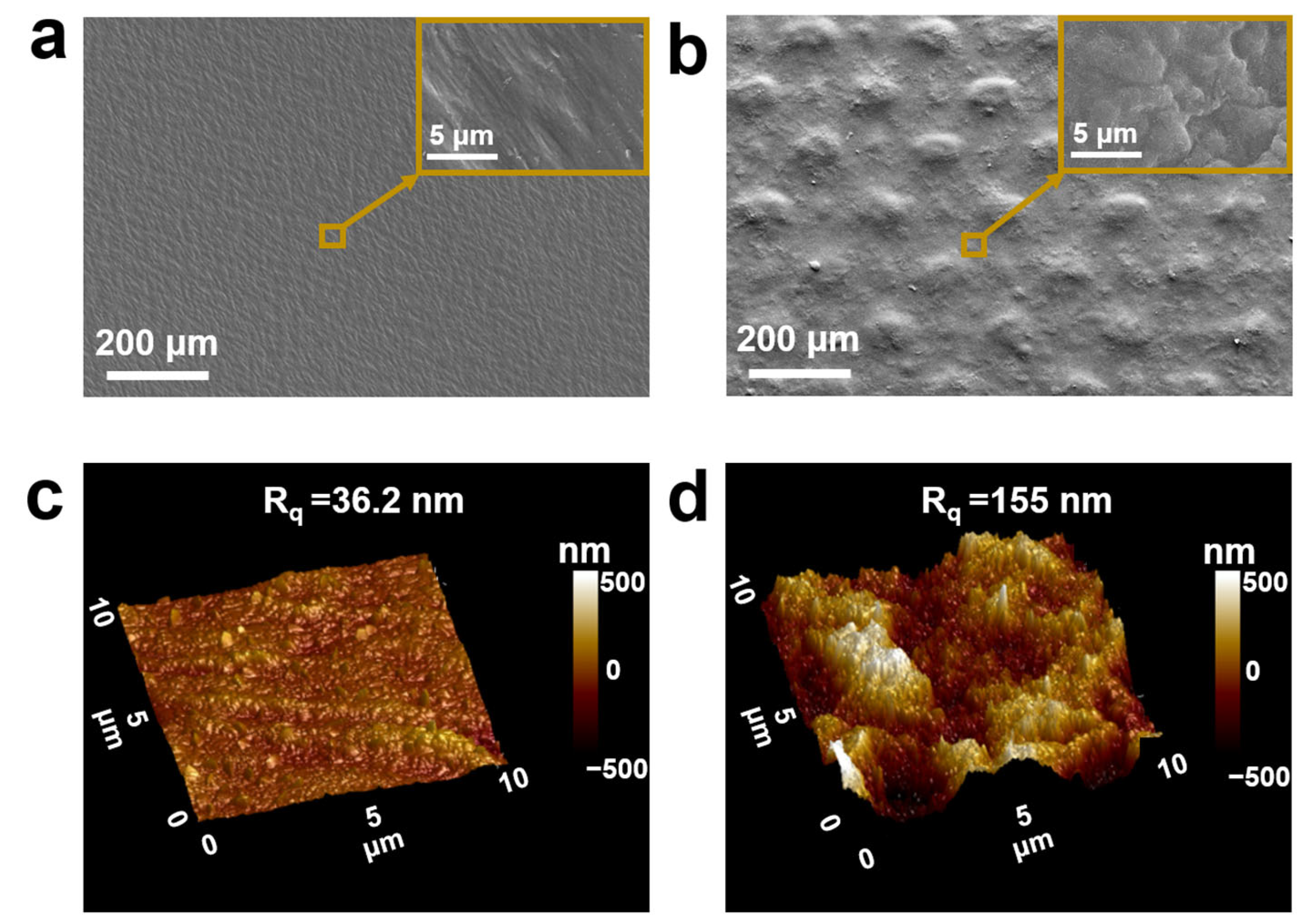
Figure 1. SEM images of the surface of different current collectors: (a) the copper foil and (b) the composite current collector; AFM images of (c) the copper foil and (d) the composite current collector.
Processes 13 00964 g001
Figure 2. Contact angle of NMP on different current collectors: (a) copper foil and (b) composite current collector; (c) N2 adsorption and desorption isotherms and (d) pore size distribution of the electrodes G-copper foil and G-composite.
Processes 13 00964 g002
Figure 3. (a) The results of the interfacial shear tests of the G-copper foil and G-composite. Inset: scheme of the experimental setup. (b) Photographs of the G-copper foil and G-composite after testing.
Processes 13 00964 g003
Figure 4. (a) First charge/discharge curves, (b) rate performance, and (c) cycling performance at 0.5 C of the G-copper foil, G-copper mesh, and G-composite.
Processes 13 00964 g004
Figure 5. (a,b) EIS mapping of the G-copper foil, G-copper mesh, and G-composite for the 3rd and 200th cycles; (c,d) the linear fitting curve of Z′ to ω−1/2. Lithium-ion diffusion coefficient: (e) discharge, (f) charging.
Processes 13 00964 g005
Figure 6. Cross-section before and after 200 cycles at 0.5 C: (a,d) G-copper foil, (b,e) G-copper mesh, and (c,f) G-composite.
Processes 13 00964 g006
Figure 7. The schematic diagram of the process of dislodging the graphite from different current collectors: (a) G-copper foil, (b) G-copper mesh, and (c) G-composite.
Processes 13 00964 g007
Disclaimer/Publisher’s Note: The statements, opinions and data contained in all publications are solely those of the individual author(s) and contributor(s) and not of MDPI and/or the editor(s). MDPI and/or the editor(s) disclaim responsibility for any injury to people or property resulting from any ideas, methods, instructions or products referred to in the content.