Abstract
The permeability of a certain mudstone interlayer in underground salt cavern gas storage (Jintan, China) is slightly high, as indicated by pressure tests (leakage rate of approximately 1~2 L/d). This layer is referred to as the “Micro-Leakage Interlayer (MLI)”. The MLI significantly impacts the tightness of gas storage, potentially leading to substantial losses. To address this problem, an experimental study was conducted. Initially, a method utilizing brine crystallization to plug the micro-leakage interlayer (MLI) was proposed. After crystallization, the porosity of the MLI cores exhibited a notable increase, and the permeability of the MLI cores increased significantly, further exacerbating the risk of gas leakage. These results indicate that the plugging solution requires further exploration. Finally, a combined plugging solution utilizing brine crystallization and ultrafine cement was proposed. Using saturated brine and waterproof coatings, an ultrafine cement slurry was prepared, and specimens were created for testing. The results indicate that the specimens exhibited a porosity of approximately 3%, a permeability below 10−19 m2, and a uniaxial compressive strength of about 40 MPa. The ultrafine cement particles had an average particle size of 3 µm, and the ultrafine cement slurry exhibited extremely low porosity and permeability, as well as high strength. The results indicate that this solution is highly feasible and can be applied to field engineering.
1. Introduction
It is well known that the permeability of rock salt is very low (less than 10−20 m2) [1,2,3]. Additionally, rock salt exhibits characteristics such as self-healing, high ductility, and suitability for water-soluble mining [4,5,6,7]. Therefore, underground salt caverns have been widely used for the long-term storage of energy resources (such as oil and gas) and radioactive waste [8,9,10,11,12]. Since the 1950s, numerous underground gas storage salt caverns have been constructed in countries such as the United States, France, Canada, and Germany for commercial short-term or seasonal storage, as well as for national strategic energy reserves [13]. By the end of 2012, 74 salt cavern gas storage facilities were established worldwide [14,15]. In 2010, gas was injected into the first newly constructed salt cavern gas storage facility in China, marking the beginning of large-scale energy storage system development in the country [16].
The study of rock salt has been pursued for many decades and has achieved considerable progress. In 1957, Gerhard proposed a method for forming and surveying caverns in salt formations [17]. The feasibility of constructing spherical cavities in underground salt domes in the United States was explored through a series of tests [18]. Durie investigated the mechanism of rock salt dissolution in underground salt cavities. He found that the dissolution rate was influenced by the rate at which fresh water was injected into the cavity [19]. Based on in situ and laboratory data, the geology and cavern stability of the Bayou Choctaw Salt Dome in the United States were studied in 1978 [20]. By conducting experiments that consider the influence of trace amounts of brine, the recrystallized microstructure of naturally deformed rock salt was reproduced. Urai et al. [21] proposed that most natural rock salt deformation occurs in the transition zone between the dislocation-creep and solution-transfer fields. Dusseault investigated the time-dependent behaviors of rock salt and developed a semi-empirical model to predict its in situ behavior [22]. He suggested that the Lotsberg Salt of central Alberta, Canada, is suitable for use in salt caverns for permanent CO2 sequestration [23]. Stormont argued that in situ gas permeability could serve as an effective method for detecting and delineating the disturbed rock zone (DRZ) around salt caverns [24]. Alkan introduced a new percolation model to predict the dilatancy-induced permeability increase in the DRZ of rock salt [25].
Unlike the thick, homogeneous, and clean rock salt deposits in countries such as the United States, Canada, and Germany, the rock salt in China exhibits several distinct characteristics, including shallow depth, limited salt thickness, and high impurity content (e.g., anhydrite, salty mudstone, sandy mudstone, and carbonates) [26,27]. Consequently, the design and operation of bedded salt storage facilities in China face significant challenges that must be addressed. Efforts are currently underway to address these potential issues. Over the past 20 years, Yang and his research team have been actively engaged in studying salt caverns in China [28,29,30,31,32,33]. Gas seepage has a significant impact on the safety of salt cavern gas storage, particularly in layered salt strata. In 1980, a gas leakage accident occurred in the Barber’s Hill salt dome (Mont Belvieu, TX, USA), which ultimately led to an explosion in a residence near Mont Belvieu [34]. Evans summarized over 200 reported incidents related to underground energy storage facilities, many of which resulted in substantial losses [35]. Leaky wellbores or faults are considered the primary causes of such leakage accidents [36]. To prevent gas leakage incidents, extensive research has been conducted in China [37,38,39].
Leakage sealing in underground storage engineering is a critical research topic that requires further investigation. During the storage of oil and natural gas, formation leakage can lead to significant engineering losses, severe environmental damage, and even casualties in extreme cases. To enhance leakage prevention and sealing efficiency in formations, Zeng et al. [40] investigated the mechanical mechanisms of fracture plugging in fractured formations using theoretical analyses and numerical simulations. Alberty and McLean [41] described a mechanism for increasing the fracture strength above the conventional minimum horizontal stress through the addition of mud additives and introduced the concept of a “stress cage”. Through mechanical analysis and simulated experiments, Wu et al. [42] proposed the use of fine-grained high-strength skeletons combined with high-temperature-resistant soft suspensions as drilling fluid-plugging agents. Their study systematically validated the sealing efficacy of this approach under downhole conditions. Li et al. [43] pointed out that the integrity of cement–salt rock interfaces (CSI) in salt cavern gas storage wells may be damaged during circulating gas injection, production, and long-term gas pressure maintenance. They indicated that extending the holding time and increasing the number of cycles can effectively improve the pore structure of CSI and enhance cement sheath integrity.
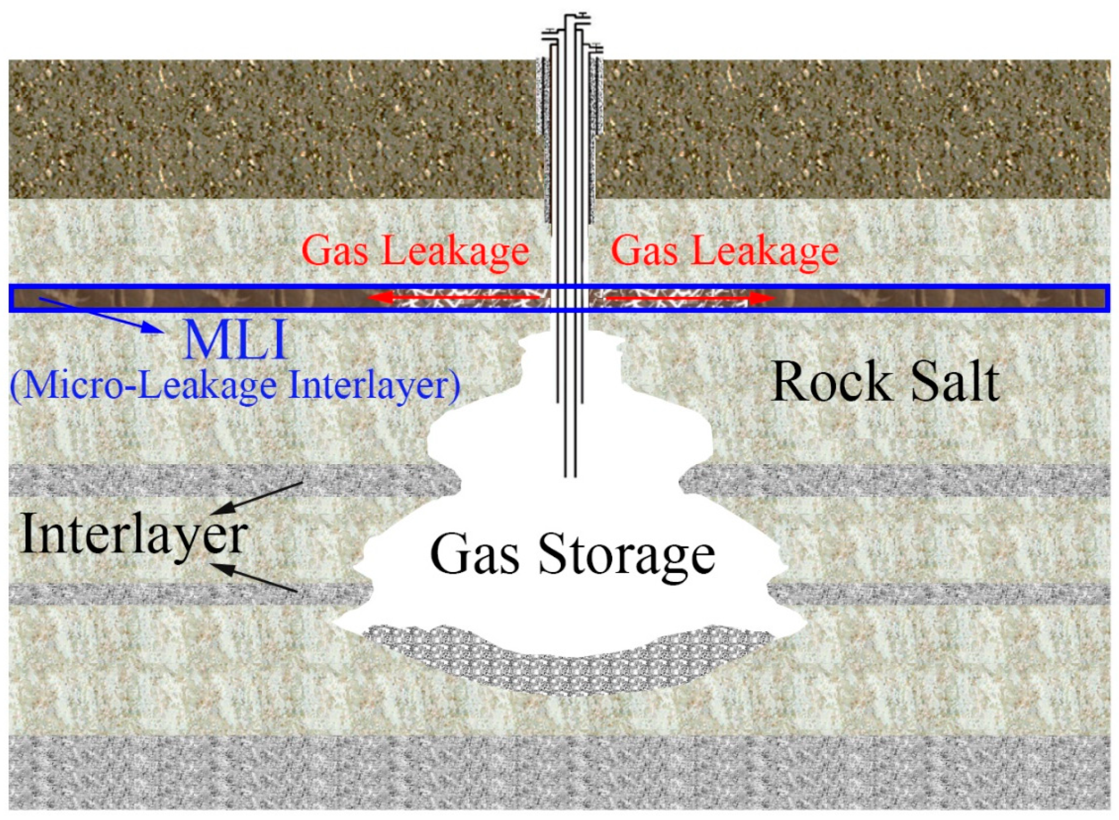
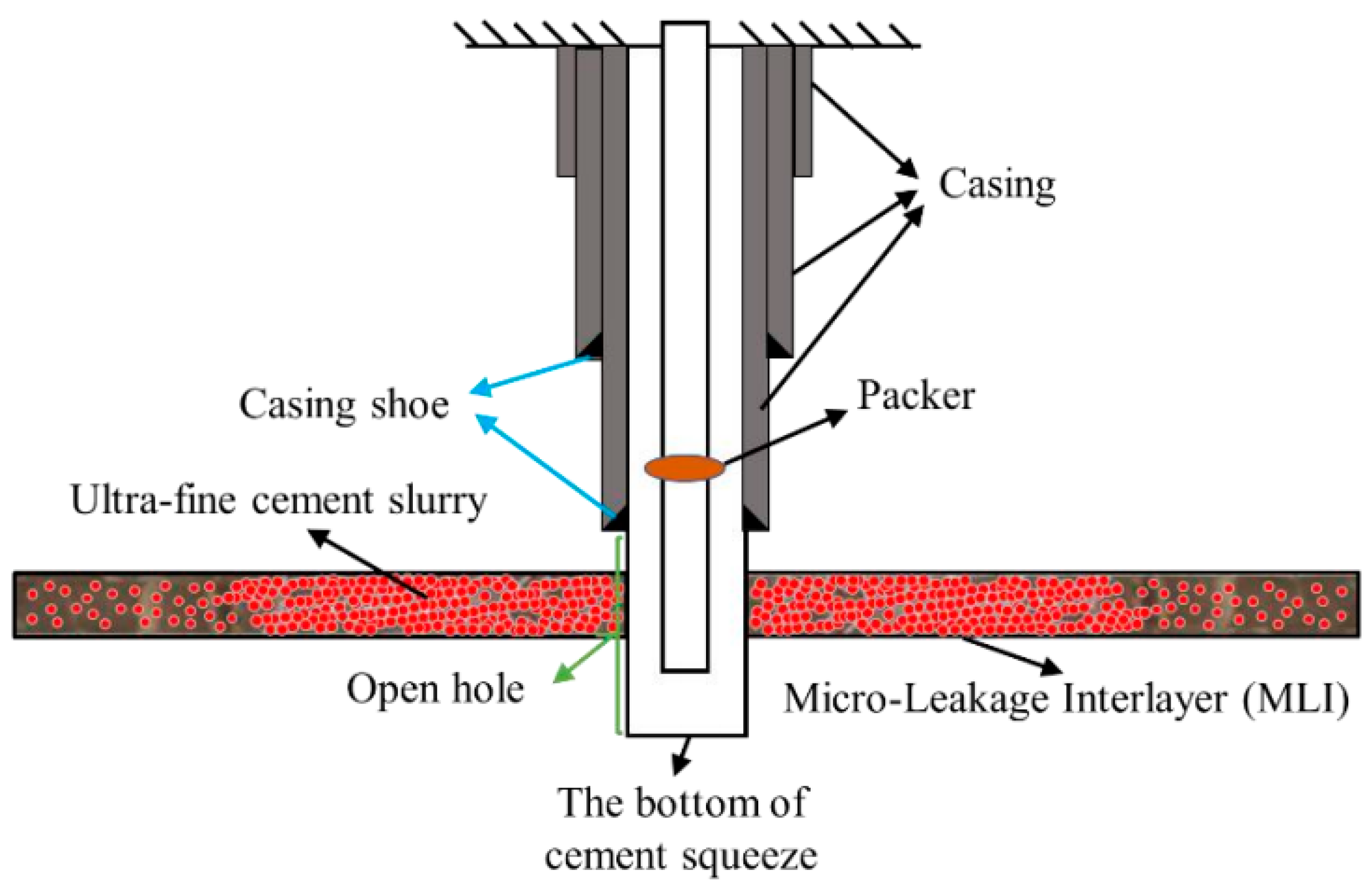
The permeability of a certain mudstone interlayer in Jintan, China, is slightly high, as indicated by recent pressure tests (with a leakage rate of approximately 1~2 L/d). This layer is referred to as the “Micro-Leakage Interlayer” (MLI). A schematic diagram of a gas storage cavern with MLI is shown in Figure 1. Based on the types of materials employed, there are several methods to plug fractured formations [44,45], such as Bridge Plugging, Gel Plugging, Cement Plugging, Composite Materials, Mechanical Methods et.al. The particle sizes of the aforementioned plugging materials are relatively large, making it difficult for them to penetrate into the MLI. As a result, they fail to achieve effective plugging performance and cannot meet the long-term operational requirements of gas storage. The presence of MLI poses a significant challenge that must be urgently addressed. To address this issue, an experimental study was conducted.
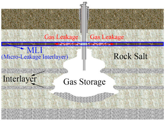
Figure 1.
Schematic diagram of gas storage with MLI (micro-leakage interlayer).
The construction of underground salt cavern gas storage relies on solution mining technology, during which salt crystals precipitate from brine when it reaches supersaturation. This study proposes a novel approach to leakage sealing using brine crystallization. The MLI samples exhibited high porosity and well-connected pore networks, enabling ultrafine cement particles to penetrate the pores. By preparing an ultrafine cement slurry with saturated brine and injecting it into the MLI under pressure, the permeability and porosity of the interlayer can be significantly reduced. This research provides practical guidance for sealing leakage interlayers in underground salt cavern gas storage, enhancing long-term operational integrity.
2. The First Solution
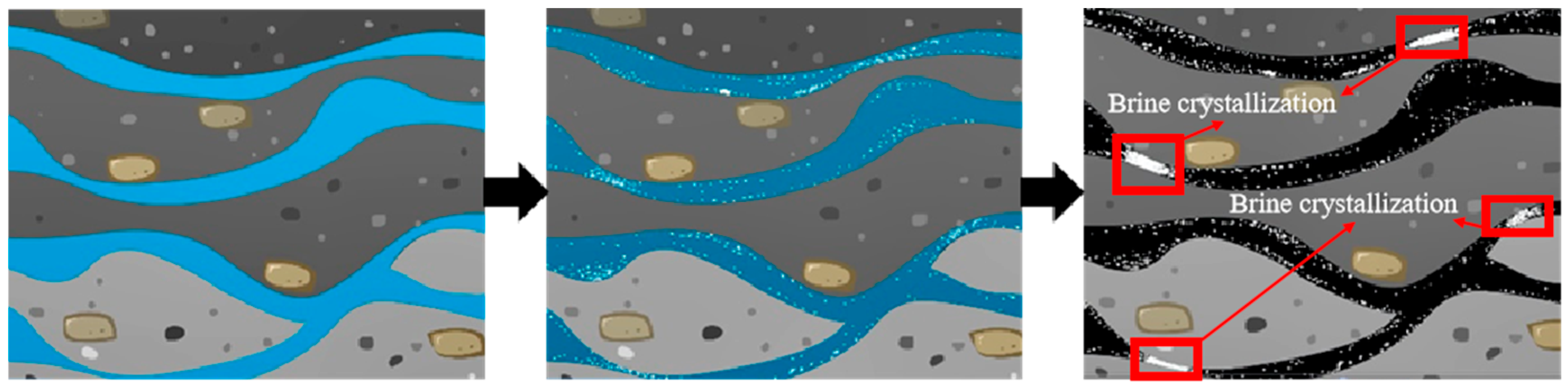
When brine becomes supersaturated, NaCl precipitates in the form of a crystal. The NaCl crystal structure is dense, with extremely low permeability, which led to the proposal of utilizing brine crystallization to plug the MLI. Experimental research was conducted on this solution, with the expectation of achieving the results illustrated in Figure 2.
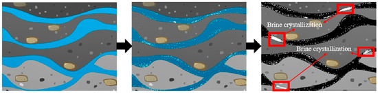
Figure 2.
The process and effect of ideal plugging with brine crystallization.
2.1. Specimen Preparation
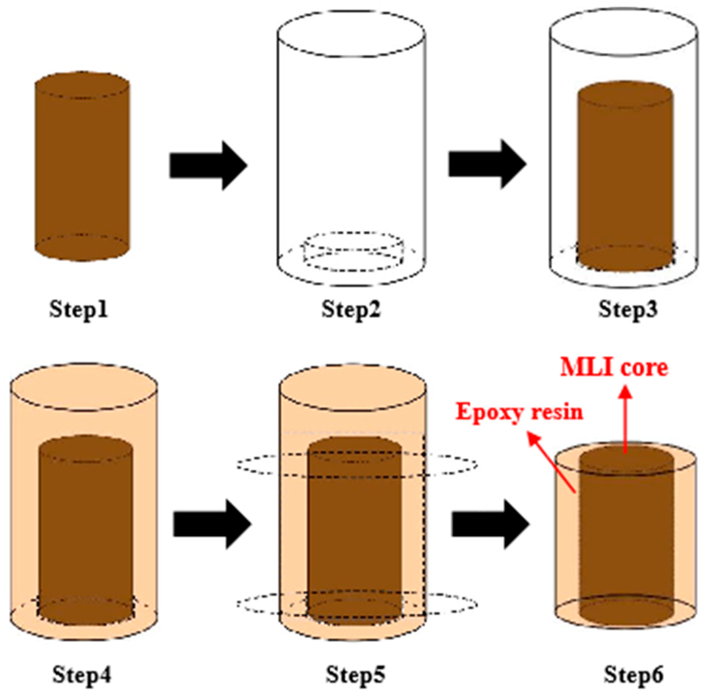
The experimental interlayer rock (MLI) was mudstone with a low salt content (ranging from 2.58% to 16.25%, as determined by XRD tests) collected from a bedded salt formation in Jintan, China. The depth of the MLI ranges from 876.60 m to 884.60 m, and its thickness is approximately 0.87 m. This interlayer is brittle and prone to breaking; therefore, we were only able to obtain six cores with a diameter of 25 mm (Figure 3). To prepare layered rock specimens, epoxy resin was used to wrap the MLI cores [46]. The specimen preparation process is illustrated in Figure 4. The specimens with a diameter of 38 mm are shown in Figure 5. Permeability tests were conducted to confirm that the permeability of the epoxy resin was extremely low (comparable to that of rock salt). The test results indicate that the permeability of the specimens (Figure 5) was the same as that of the original cores (without epoxy resin, Figure 3).
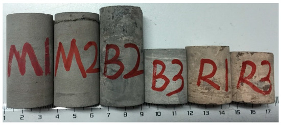
Figure 3.
The MLI cores.
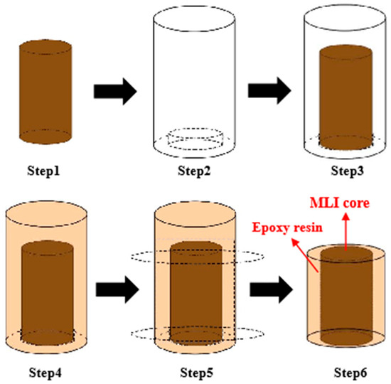
Figure 4.
The process of preparing specimens.
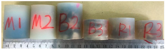
Figure 5.
The MLI specimens wrapped by epoxy resin.
2.2. Test Results and Analysis
To evaluate the effectiveness of brine crystallization plugging, porosity and permeability tests were conducted before and after the crystallization process. The crystallization process for the specimens was as follows: first, the specimens were soaked in saturated brine (at a temperature of 50 °C and a pressure of 12 MPa) for 7 days; then, brine crystallization was induced within the specimens through evaporation.
2.2.1. SEM Tests
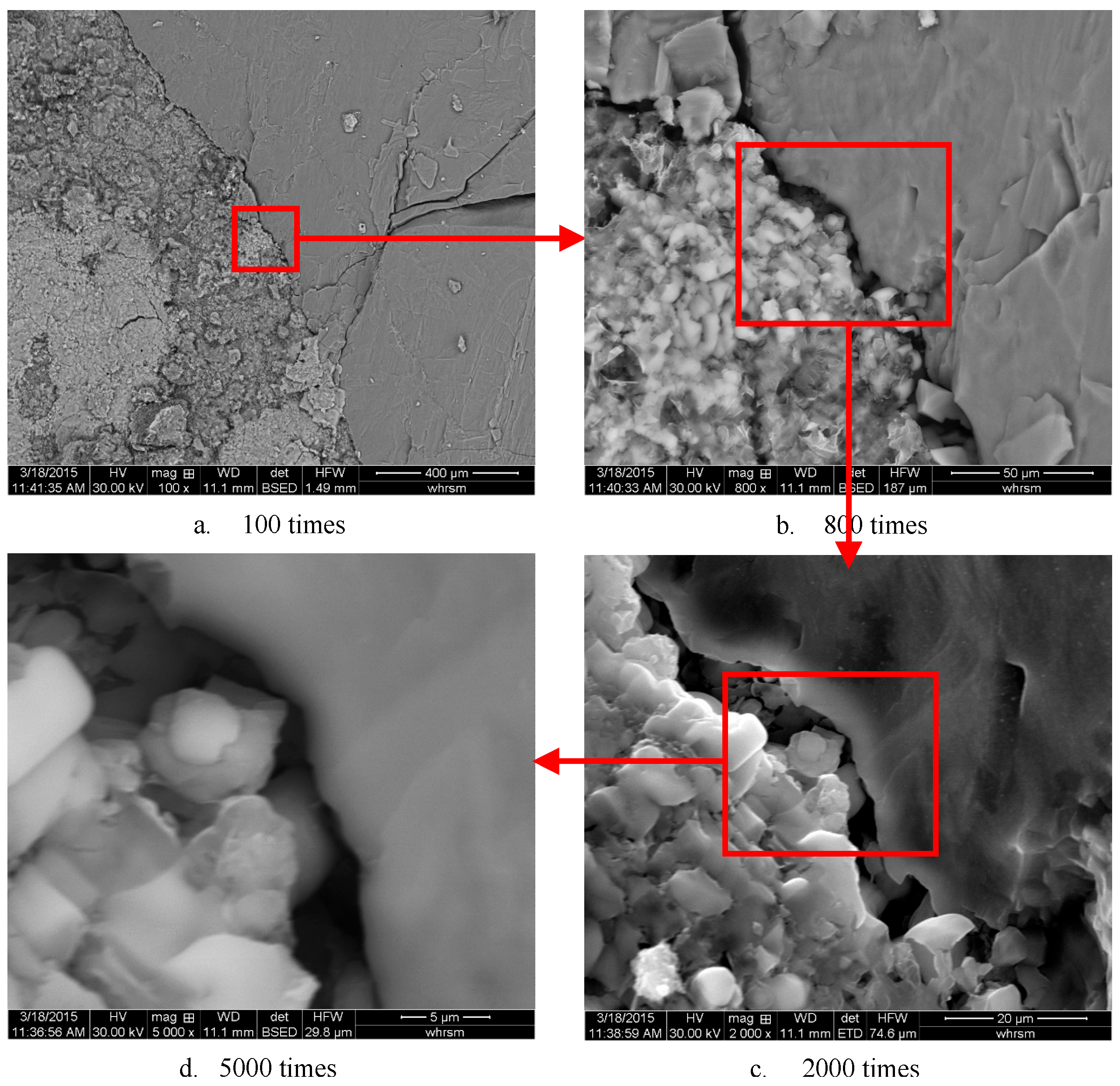
Scanning electron microscopy (SEM) was used to determine the microstructure of the MLI cores. Some of the resulting images are shown in Figure 6.

Figure 6.
SEM pictures of MLI (micro-leakage interlayer) core.
From Figure 6, it can be observed that the MLI core is heterogeneous. The core contained cracks with widths of approximately 5 μm and pores. Under stratum conditions, these pores serve as potential channels for the migration of brine. The core also contained clay minerals, including illite (about 22.24%), montmorillonite (about 3.71%), and kaolinite (about 3.19%). When brine migrates through the cores, water may be absorbed by clay minerals, leading to supersaturation. As a result, crystallization may gradually occur within the pores and cracks.
2.2.2. Porosity Tests
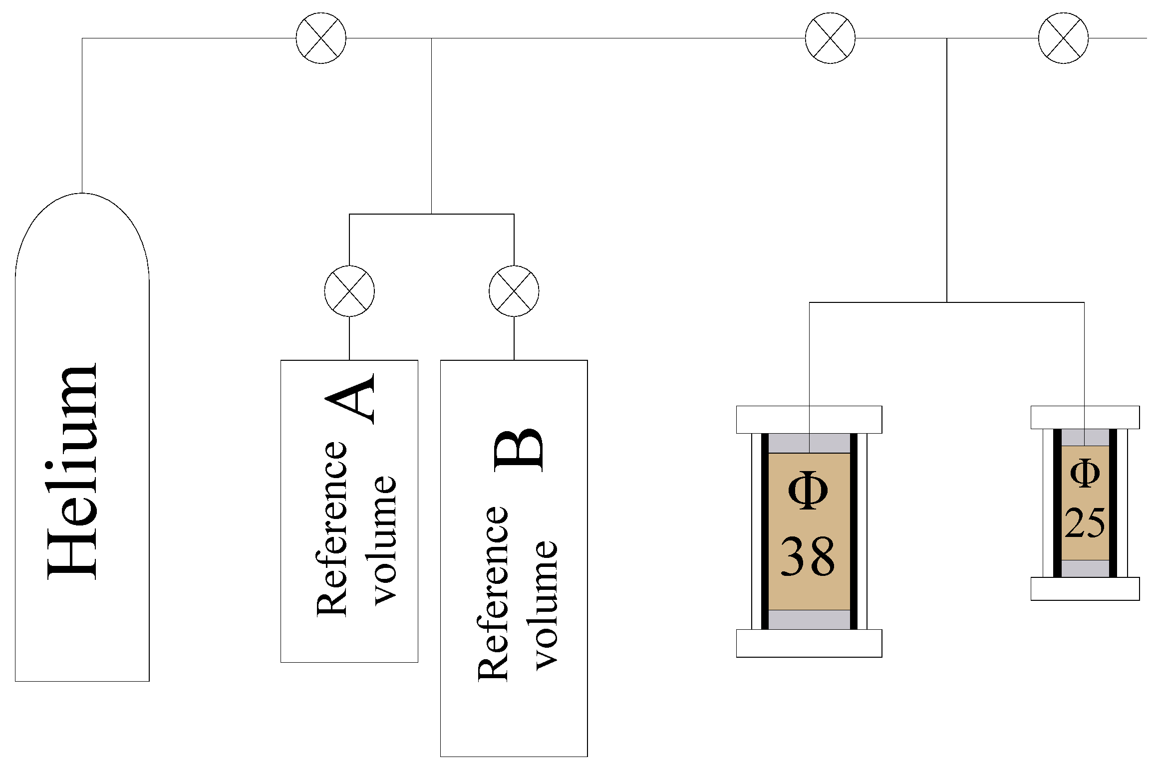
A helium porosity measuring instrument (Figure 7) was used to determine the porosity of the specimens. Helium molecules have the advantages of small size, stable properties, and minimal adsorption on the surface of clay minerals. As a result, it is easy to obtain accurate measurements without damaging the specimens. The results of the porosity tests are presented in Table 1.
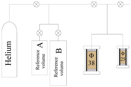
Figure 7.
Schematic diagram of the helium porosity measurement. Φ38 represents a core with a diameter of 38 mm, and Φ25 represents a core with a diameter of 25 mm.

Table 1.
The results of porosity tests.
Table 1 shows that the porosities of the specimens increase significantly after crystallization, particularly for B2. In saturated brine, the clay minerals in the MLI core may absorb water, leading to expansion, which simultaneously promotes crack propagation. The dissolution and crystallization of salt occur in a dynamically balanced manner. The dissolution of salt in the MLI cores may further facilitate the formation and propagation of cracks. Under actual stratum conditions, the porosity of the interlayer is unlikely to change significantly due to the high formation pressure. Additionally, crystallization should partially block the pore pathways. However, the laboratory test appears to have certain limitations.
2.2.3. Permeability Tests
The permeability of the specimens was tested under steady nitrogen (N2) gas flow using a low-permeability measurement instrument. The flowchart of this instrument (Figure 8) was designed in accordance with the standards of the American Petroleum Institute [47].
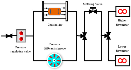
Figure 8.
The flow chart of the Low permeability measurement instrument.
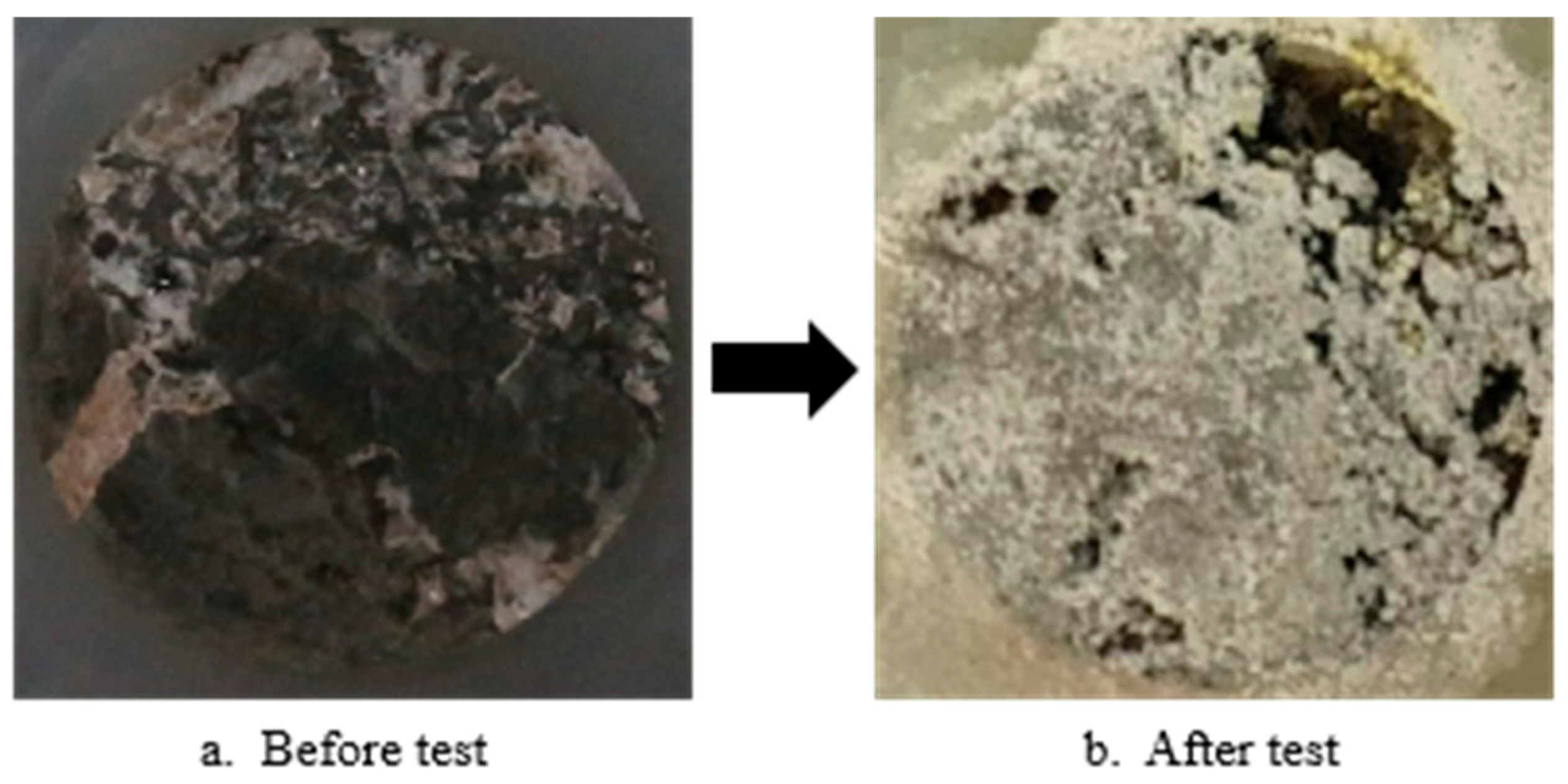
During the test, the gas flow is vertical. The confining pressure is 1.38 MPa. The outlet pressure is 0.10 MPa, and the temperature is 25 °C. Table 2 presents the permeability results. The permeability of the MLI cores is on the order of 10−16 m2, which is far greater than that of rock salt (less than 10−20 m2). This high permeability contributes to gas leakage through the MLI. The results demonstrate that the permeability of the specimens increases substantially after crystallization, particularly for sample B2. During the test, the clay minerals within the MLI core may absorb water, leading to expansion and simultaneous crack propagation. The dissolution and crystallization of salt occur in a dynamic equilibrium. The dissolution of salt within the MLI cores likely facilitates the formation and propagation of cracks, as illustrated in Figure 9. Consequently, the permeability increases significantly.
Table 2.
The results of permeability tests.
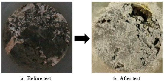
Figure 9.
The surface characteristics of the specimen (e.g., B2) before and after the test.
2.2.4. CT Tests
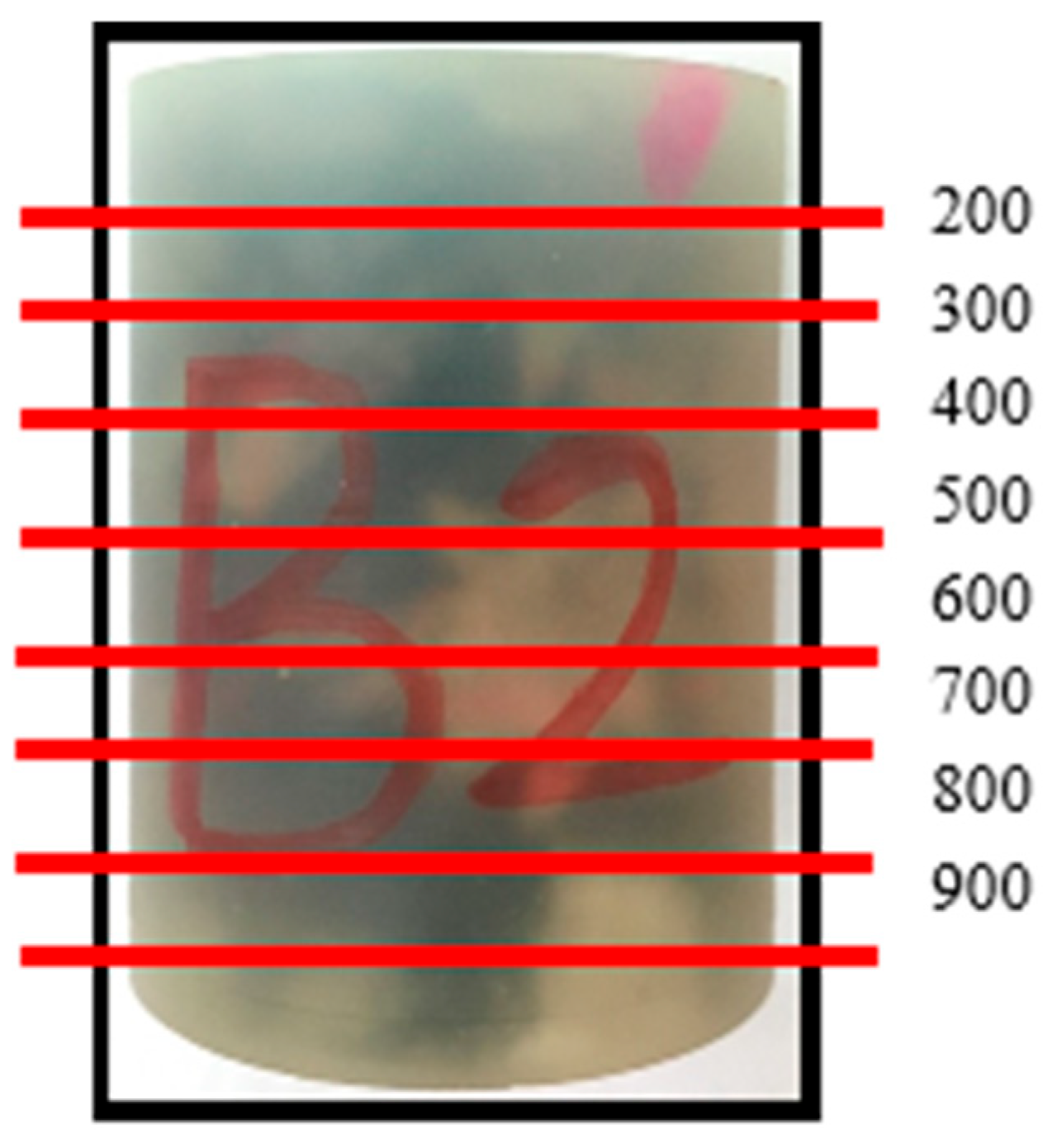
To investigate the internal structural changes in the specimens before and after crystallization, CT scanning was performed using a Zeiss Xradia 410 Versa instrument (Carl Zeiss AG, Aalen, Germany), which offers a spatial resolution of 0.7 μm. Due to the high cost associated with the process, only three specimens (B2, M1, and R1) were selected for scanning. A total of 1014 CT images were acquired for each specimen. Among these, specimen B2 was selected for a detailed analysis. B2 is an MLI core with minimal salt content, measuring 37.93 mm in diameter and 51.09 mm in height.
Due to the lack of clarity in the images of the upper and lower sections, we selected and analyzed images numbered 200 to 900 for further examination (Figure 10). Using the AVIZO (version 2020.1) software, we performed 3D reconstruction of specimen B2 both before and after crystallization. During this process, the epoxy resin components were excluded from visualization (Figure 11).
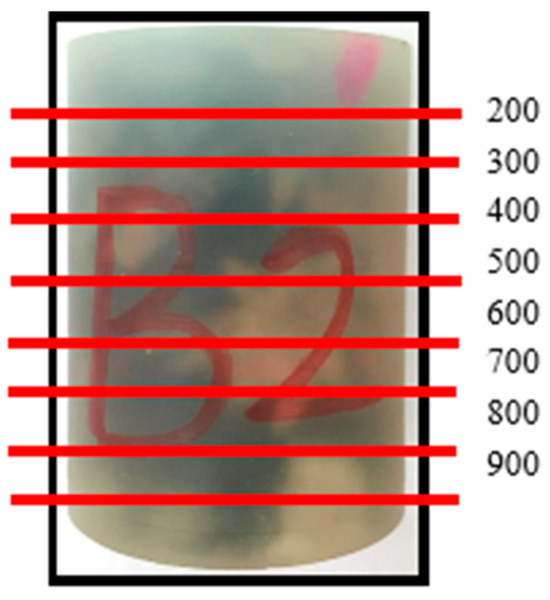
Figure 10.
MLI specimen number B2.
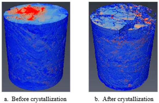
Figure 11.
3D reconstruction of specimen B2 before and after crystallization.
The CT images were processed using MATLAB (R2020a) software, and eight representative images were selected for a detailed analysis. As shown in Figure 12, the initial cracks in the MLI specimens exhibited significant propagation after crystallization, particularly by scans 200, 300, 400, and 500. In a saturated brine environment, the dissolution and crystallization of salt occur in a dynamic equilibrium. The partial dissolution of salt in specimen B2 likely facilitated the formation and propagation of cracks, as evidenced by scans 700, 800, and 900 (Figure 12).
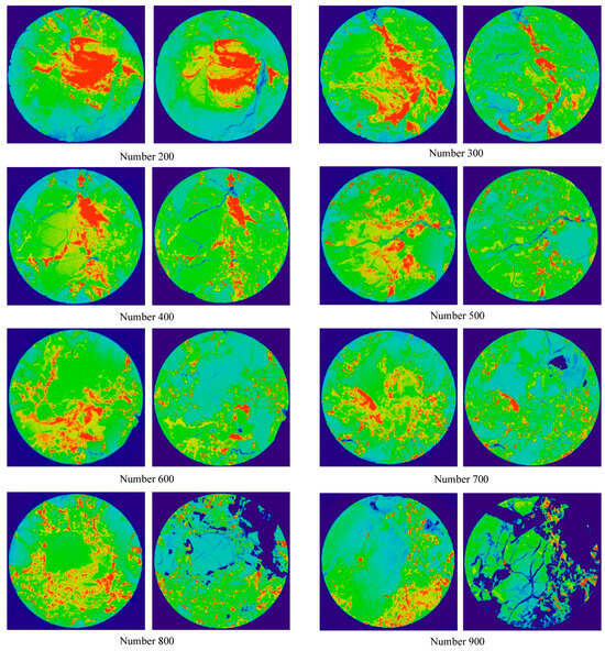
Figure 12.
CT images of specimen B2 before (left) and after (right) crystallization.
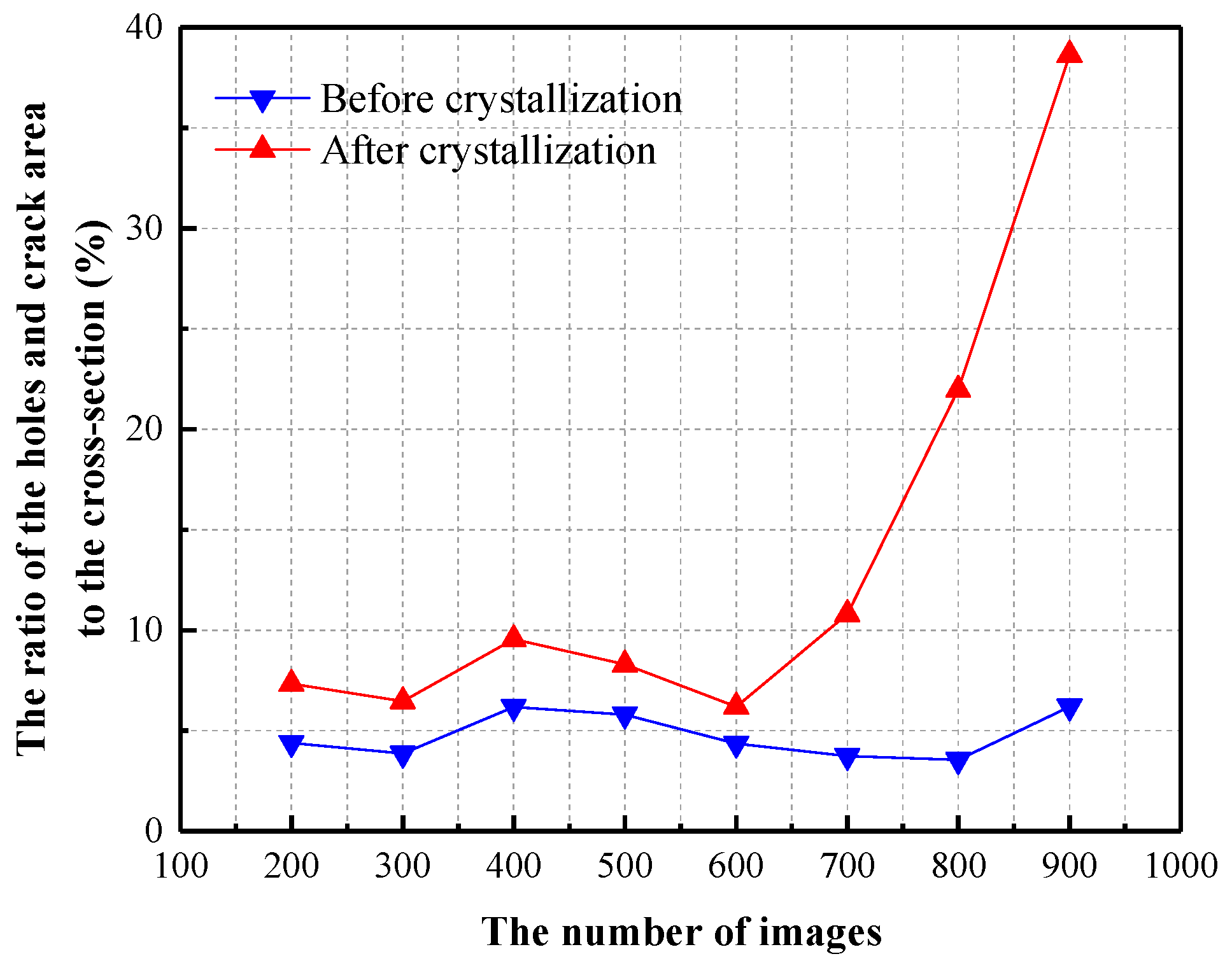
The ratio of the area of the holes and cracks to the total cross-sectional area was calculated for each of the eight analyzed images. As illustrated in Figure 13, this ratio exhibits a significant increase after crystallization, particularly in scans 700, 800, and 900. These results demonstrate that crystallization plays a critical role in promoting the formation and propagation of cracks within the MLI core, ultimately leading to an increase in the porosity.

Figure 13.
Ratio of the holes and cracks area to the cross-section before and after crystallization.
2.3. Result Analysis
After crystallization, it was observed that the initial cracks in the MLI specimens propagated, and both porosity and permeability increased. These results indicate that the plugging solution requires further exploration.
3. The Second Solution
From the results of the first solution, it can be observed that the porosity and permeability of the MLI specimens increased after crystallization, and the internal pores of the specimens became more developed. This is because the MLI specimens inherently have a high salt content, coupled with a high clay mineral content. When brine infiltrates the specimens, the internal salts dissolve, and the clay minerals expand upon contact with water, leading to the development and extension of the internal fractures. This results in an increase in both porosity and permeability.
In drilling engineering, the cement slurry is commonly used to plug fractured formations. However, MLI exhibits better gas tightness compared to typical fractured formations, and ordinary cement slurry, with its larger particle size, struggles to penetrate the fine pores of the micro-permeable layers. As a result, using ordinary cement slurry may lead to incomplete plugging and fail to achieve the desired effect.
Ultrafine cement particles are significantly smaller than those of ordinary cement, which makes ultrafine cement particularly suitable for plugging the MLI. In the preparation of ultrafine cement grout, it is essential to use saturated brine instead of fresh water. This is because unsaturated saline solutions can dissolve salts present in the mudstone of the MLI and cause the swelling of clay minerals. During the curing process of the ultrafine cement grout, saturated brine inevitably forms salt crystals, which further densify the grout and enhance its sealing effectiveness. The ultrafine cement slurry to be prepared must meet the following requirements:
- (1)
- Exhibit fine particle size for microcrack penetration: The cement particles must be ultrafine to ensure that the slurry can effectively penetrate the MLI.
- (2)
- Exhibit excellent filling performance. The slurry should exhibit low porosity and low permeability after hardening, ensuring that it can completely fill the voids and create a dense, impermeable barrier.
- (3)
- Exhibit high-pressure resistance and strength. The hardened slurry must possess sufficient strength to withstand high pressures to ensure long-term stability and effectiveness.
This method is referred to as Brine Crystallization Combined with Ultrafine Cement Grouting Solution. The expected effect of this solution is illustrated in Figure 14.
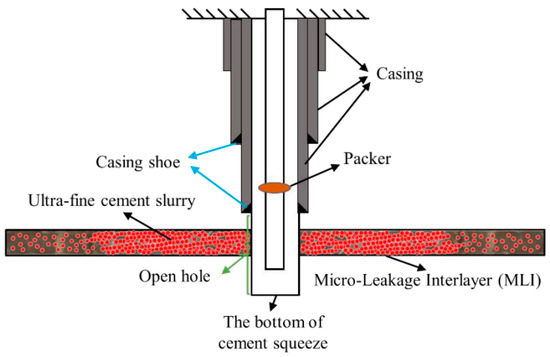
Figure 14.
The solution of Brine Crystallization Combined with Ultrafine Cement Grouting and the expected effect.
3.1. Specimen Preparation
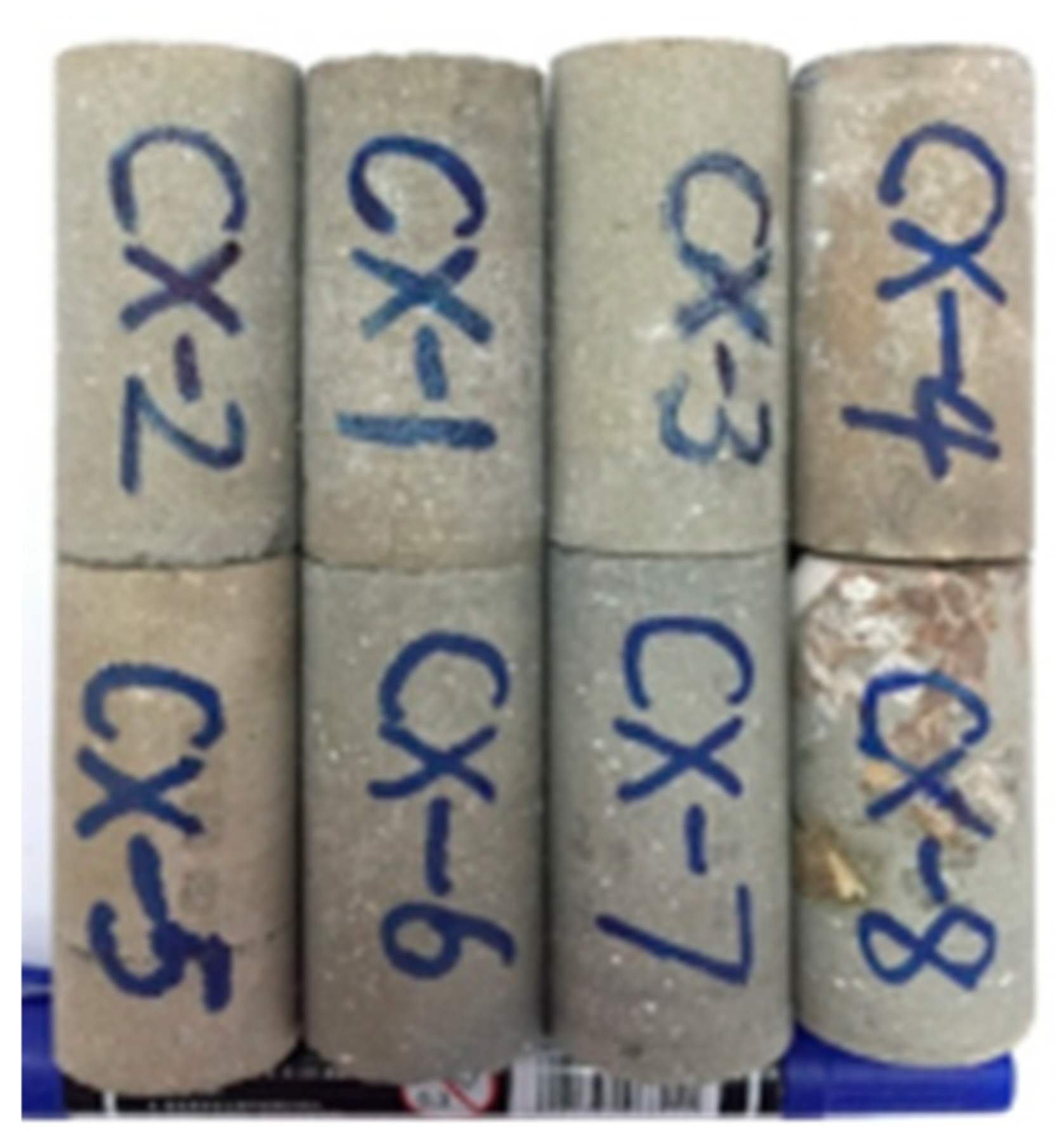
The ultrafine cement particles used in this study have an average particle size of 3 µm, with a distribution range of 0.2–18 µm. Notably, 80% of the particles are smaller than 5 µm, which ensures their ability to flow effectively into the pores and fractures of the MLI. Water can lead to the formation and expansion of fractures in the MLI. This results in increased permeability and reduced strength of the geological formation. To mitigate this issue, saturated brine and waterproof coatings were employed as substitutes for water during the preparation of ultrafine cement grout. The optimal ratio for the grout mixture is 0.44:1.00:0.02 (Saturated Brine: Ultrafine Cement: Waterproof Coating). The ultrafine cement grout has an initial viscosity of 70 mPa·s and an initial setting time of 300 min. The ultrafine cement grout was subjected to conditions simulating actual field operations: (1) Temperature: 50 °C; (2) Pressure: 25 MPa. After curing, cylindrical specimens with a diameter of 25 mm and a height of 50 mm were prepared for further testing. The specimens are shown in Figure 15.

Figure 15.
The produced standard specimens.
3.2. Test Results and Analysis
3.2.1. Porosity and Permeability Tests
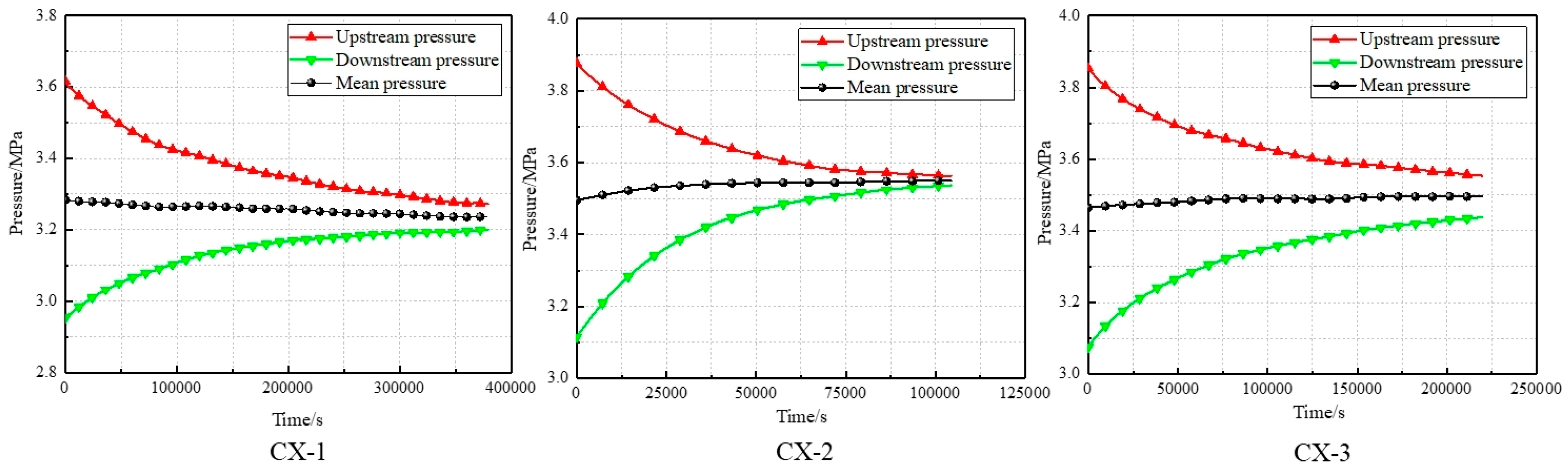
The porosity and permeability of the ultrafine cement slurry after solidification are critical parameters for plugging. To obtain this information, porosity and permeability tests were conducted on the specimens. Due to the dense nature of the specimens, the pulse decay method was employed to measure the permeability. Figure 16 illustrates the pressure-time curve obtained from the permeability test, while Table 3 presents the results of the porosity and permeability measurements.
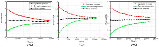
Figure 16.
The pressure-time curves during the tests.
Table 3.
The porosity and permeability test results.
As shown in Figure 16, the permeability test for specimen CX-1 lasted 379,200 s (approximately 105 h), for specimen CX-2, 104,400 s (approximately 29 h), and for specimen CX-3, 219,600 s (approximately 61 h). The extended duration of the tests indicates that the permeability of the specimens is extremely low, with poor internal pore connectivity. From Table 3, it can be observed that the porosity of the specimens is approximately 3%, and the permeability is below 10−19 m2. After solidification, the porosity and permeability of the ultrafine cement are significantly lower than those of the MLI and other mudstone interlayers, and are comparable to those of salt rock. This demonstrates that the ultrafine cement slurry exhibits excellent filling properties and that the Brine Crystallization Combined with Ultrafine Cement Grouting Solution is highly feasible.
3.2.2. Strength Tests
Based on the experience gained from the construction and operation of underground salt cavern gas storage in Jintan, the maximum operating pressure for an underground salt cavern gas storage at a depth of approximately 1000 m should be 18 MPa. Taking into account the formation pressure, the ultrafine cement slurry must possess sufficient strength to ensure that it does not fail under stress after plugging. To determine the strength of the specimens, uniaxial compression tests were conducted, and the stress-strain curve is shown in Figure 17. According to previous studies, the uniaxial compressive strength of salt rock in Jintan is approximately 19 MPa, while that of mudstone is about 34 MPa. The elastic modulus of salt rock is around 3.90 GPa, and that of mudstone is approximately 4.72 GPa. As shown in Figure 17, the uniaxial compressive strength of the cured ultrafine cement specimen is about 40 MPa, with an average elastic modulus of around 6.49 GPa. This indicates that the ultrafine cement slurry meets the strength requirements, demonstrating that the Brine Crystallization Combined with Ultrafine Cement Grouting Solution is highly feasible.

Figure 17.
The stress-strain curve of ultrafine cement sample under uniaxial compression.
3.3. Result Analysis
The test results have demonstrated that the ultrafine cement slurry exhibits extremely low porosity and permeability, along with high strength, making it capable of meeting plugging requirements. The ultrafine cement particles are characterized by their small size, large specific surface area, and rapid hydration rate, which accelerate the gelation and thickening processes, significantly influencing the performance of the ultrafine cement slurry. The relatively dense salt crystals formed by brine can further enhance the plugging effectiveness of the ultrafine cement slurry. The Brine Crystallization Combined with an Ultrafine Cement Grouting Solution is highly feasible.
4. Summary and Conclusions
The MLI significantly impacts the tightness of gas storage systems, potentially leading to substantial and immeasurable losses. This presents a critical challenge that must be urgently addressed. To address this issue, an experimental study was conducted. Two plugging solutions were proposed, and experimental tests and feasibility analyses were conducted, yielding the following key conclusions:
- (1)
- The permeability of the MLI cores is on the order of 10−16 m2, which is significantly higher than that of rock salt (less than 10−20 m2). This elevated permeability is the primary factor contributing to gas leakage through the MLI.
- (2)
- For the solution of brine crystallization. After crystallization, the porosity of the MLI cores exhibits a notable increase, indicating structural changes within the material. Similarly, the permeability of the MLI cores increases significantly post-crystallization, further exacerbating the risk of gas leakage. These results indicate that the plugging solution requires further exploration.
- (3)
- For the Brine Crystallization Combined with Ultrafine Cement Grouting Solution. The ultrafine cement particles have an average particle size of 3 µm, and the ultrafine cement slurry exhibits extremely low porosity and permeability, along with high strength. The salt crystals formed by brine can further enhance the plugging effectiveness of the slurry. The results indicate that this solution is highly feasible.
The second solution can be attempted for on-site application in gas storage projects. After implementation, a gas-tightness test should be conducted to verify the sealing effectiveness.
Author Contributions
Conceptualization, H.Y. and X.G.; methodology, H.Y.; software, H.Y.; validation, H.Y. and X.G.; formal analysis, H.Y.; investigation, H.Y.; writing—original draft preparation, H.Y.; writing—review and editing, X.G. All authors have read and agreed to the published version of the manuscript.
Funding
This research was funded by the China Scholarship Council (No. 201704910741), the National Natural Science Foundation of China [Nos. 51774266, 51404241, 41602328, 52404060].
Data Availability Statement
The original contributions presented in this study are included in the article. Further inquiries can be directed to the corresponding author.
Acknowledgments
The authors are sincerely grateful to Jaak J Daemen, Mackay School of Earth Sciences and Engineering, University of Nevada, for his thoughtful review of this paper. Moreover, the authors wish to thank the reviewers for constructive comments and suggestions that have helped us improve our manuscript.
Conflicts of Interest
Author Hongwu Yin was employed by Guangzhou Expressway Co., Ltd. The remaining author declares that the research was conducted in the absence of any commercial or financial relationships that could be construed as a potential conflict of interest.
References
- Peach, C.J. Influence of Deformation on the Fluid Transport Properties of Salt Rocks. Fac. Aardwetenschappen Rijksuniv. Utrecht 1991, 77, 238. [Google Scholar]
- Schulze, O.; Popp, T.; Kern, H. Development of damage and permeability in deforming rock salt. Eng. Geol. 2001, 61, 163–180. [Google Scholar] [CrossRef]
- Stormont, J.C.; Daemen, J.J.K. Laboratory study of gas permeability changes in rock salt during deformation. Int. J. Rock Mech. Min. Sci. Geomech. Abstr. 1992, 29, 325–342. [Google Scholar] [CrossRef]
- Hunsche, U.; Hampel, A. Rock salt—The mechanical properties of the host rock material for a radioactive waste repository. Eng. Geol. 1999, 52, 271–291. [Google Scholar] [CrossRef]
- Li, J.; Shi, X.; Wang, T.; Yang, C.; Li, Y.; Ma, H.; Ma, X.; Shi, H. A prediction model of the accumulation shape of insoluble sediments during the leaching of salt cavern for gas storage. J. Nat. Gas Sci. Eng. 2016, 33, 792–802. [Google Scholar] [CrossRef]
- Li, Y.; Liu, W.; Yang, C.; Daemen, J.J.K. Experimental investigation of mechanical behavior of bedded rock salt containing inclined interlayer. Int. J. Rock Mech. Min. Sci. 2014, 69, 39–49. [Google Scholar] [CrossRef]
- Liu, W.; Li, Y.; Yang, C.; Daemen, J.J.K.; Yang, Y.; Zhang, G. Permeability characteristics of mudstone cap rock and interlayers in bedded salt formations and tightness assessment for underground gas storage caverns. Eng. Geol. 2015, 193, 212–223. [Google Scholar] [CrossRef]
- Bérest, P.; Bergues, J.; Brouard, B.; Durup, J.G.; Guerber, B. A salt cavern abandonment test. Int. J. Rock Mech. Min. Sci. 2001, 38, 357–368. [Google Scholar] [CrossRef]
- Ma, H.; Yang, C.; Li, Y.; Shi, X.; Liu, J.; Wang, T. Stability evaluation of the underground gas storage in rock salts based on new partitions of the surrounding rock. Environ. Earth Sci. 2015, 73, 6911–6925. [Google Scholar] [CrossRef]
- Yang, C.; Daemen, J.J.K.; Yin, J.H. Experimental investigation of creep behavior of salt rock. Int. J. Rock Mech. Min. Sci. 1999, 36, 233–242. [Google Scholar] [CrossRef]
- Zhang, G.; Li, Y.; Yang, C.; Daemen, J.J.K. Stability and tightness evaluation of bedded rock salt formations for underground gas/oil storage. Acta Geotech. 2014, 9, 161–179. [Google Scholar] [CrossRef]
- Zhang, N.; Shi, X.; Wang, T.; Yang, C.; Liu, W.; Ma, H.; Daemen, J.J.K. Stability and availability evaluation of underground strategic petroleum reserve (SPR) caverns in bedded rock salt of Jintan, China. Energy 2017, 134, 504–514. [Google Scholar] [CrossRef]
- Yang, C.; Wang, T.; Li, Y.; Yang, H.; Li, J.; Qu, D.; Xu, B.; Yang, Y.; Daemen, J.J.K. Feasibility analysis of using abandoned salt caverns for large-scale underground energy storage in China. Appl. Energy 2015, 137, 467–481. [Google Scholar] [CrossRef]
- Li, J.; Shi, X.; Yang, C.; Li, Y.; Wang, T.; Ma, H. Mathematical model of salt cavern leaching for gas storage in high-insoluble salt formations. Sci. Rep. 2018, 8, 372. [Google Scholar] [CrossRef]
- Ozarslan, A. Large-scale hydrogen energy storage in salt caverns. Int. J. Hydrogen Energy 2012, 37, 14265–14277. [Google Scholar] [CrossRef]
- Li, Y.; Yang, C.; Shi, X. Cavity Control and Safety Assessment of Salt Cavern Gas Storage; Science Press: Beijing, China, 2012. [Google Scholar]
- Gerhard, H.; Stelzer, R.B. Method for Forming and Surveying a Cavern in a Salt Formation. U.S. Patent US2786661, 26 March 1957. [Google Scholar]
- U.S. Department of Energy Office of Scientific and Technical Information. Feasibility of Creating Spherical Cavities in Underground Salt Domes; Progress Report, February and March 1963; U.S. Department of Energy Office of Scientific and Technical Information: Oak Ridge, TN, USA, 1963. [Google Scholar]
- Durie, R.W. Mechanism of the dissolution of salt in the formation of underground salt cavities. Soc. Pet. Eng. J. 1964, 4, 183–190. [Google Scholar] [CrossRef]
- Thomas, R.L.; Hendron, A.J. Strategic Petroleum Reserve Program: Salt Dome Geology and Cavern Stability Analysis, Bayou Choctaw, Louisiana; Parsons, Brinckerhoff, Quade and Douglas, Inc.: New York, NY, USA; Louis Records and Associates, Inc.: Torrance, CA, USA, 1978. [Google Scholar]
- Urai, J.L.; Spiers, C.J.; Zwart, H.J.; Lister, G.S. Weakening of rock salt by water during long-term creep. Nature 1986, 324, 554–557. [Google Scholar] [CrossRef]
- Dusseault, M.B.; Fordham, C.J. Time-dependent Behavior of Rocks. In Rock Testing & Site Characterization; Pergamon: İzmir, Turkey, 1993; pp. 119–149. [Google Scholar]
- Dusseault, M.B.; Rothenburg, L.; Bachu, S. Sequestration of CO in Salt Caverns. J. Can. Pet. Technol. 2002, 43, 49–55. [Google Scholar]
- Stormont, J.C. In situ gas permeability measurements to delineate damage in rock salt. Int. J. Rock Mech. Min. Sci. 1997, 34, 1055–1064. [Google Scholar] [CrossRef]
- Alkan, H. Percolation model for dilatancy-induced permeability of the excavation damaged zone in rock salt. Int. J. Rock Mech. Min. Sci. 2009, 46, 716–724. [Google Scholar] [CrossRef]
- Liang, W.; Yang, C.; Zhao, Y.; Dusseault, M.B.; Liu, J. Experimental investigation of mechanical properties of bedded salt rock. Int. J. Rock Mech. Min. Sci. 2007, 44, 400–411. [Google Scholar] [CrossRef]
- Yin, H.; Ma, H.; Chen, X.; Shi, X.; Yang, C.; Dusseault, M.; Zhang, Y. Synthetic Rock Analogue for Permeability Studies of Rock Salt with Mudstone. Appl. Sci. 2017, 7, 946. [Google Scholar] [CrossRef]
- Li, Y.; Chen, Y.; Zhang, G.; Liu, Y.; Zhou, C. A numerical procedure for modeling the seepage field of water-sealed underground oil and gas storage caverns. Tunn. Undergr. Space Technol. 2017, 66, 56–63. [Google Scholar] [CrossRef]
- Li, Y.; Yang, C. On fracture saturation in layered rocks. Int. J. Rock Mech. Min. Sci. 2007, 44, 936–941. [Google Scholar] [CrossRef]
- Shi, X.; Liu, W.; Chen, J.; Jiang, D.; Wu, F.; Zhang, J.; Fan, J. Softening model for failure analysis of insoluble interlayers during salt cavern leaching for natural gas storage. Acta Geotech. 2018, 13, 801–816. [Google Scholar] [CrossRef]
- Yang, C.; Li, Y.; Chen, F. Bedded Salt Rock Mechanics and Engineering; Science Press: Beijing, China, 2009. (In Chinese) [Google Scholar]
- Yang, C.H.; Liang, W.G.; Wei, D.H.; Yang, H.J. Investigation on possibility of energy storage in salt rock in China. Chin. J. Rock Mech. Eng. 2005, 24, 4409–4417. [Google Scholar]
- Zhang, G.; Li, Y.; Daemen, J.J.K.; Yang, C.; Wu, Y.; Zhang, K.; Chen, Y. Geotechnical Feasibility Analysis of Compressed Air Energy Storage (CAES) in Bedded Salt Formations: A Case Study in Huai’an City, China. Rock Mech. Rock Eng. 2015, 48, 2111–2127. [Google Scholar] [CrossRef]
- Thoms, R.L.; Gehle, R.M. A Brief History of Salt Cavern Use; Elsevier: Amsterdam, The Netherlands, 2000. [Google Scholar]
- Evans, D.J. A review of underground fuel storage events and putting risk into perspective with other areas of the energy supply chain. Geol. Soc. Lond. Spec. Publ. 2009, 313, 173–216. [Google Scholar] [CrossRef]
- Chen, M.; Buscheck, T.A.; Wagoner, J.L.; Sun, Y.; White, J.A.; Chiaramonte, L.; Aines, R.D. Analysis of fault leakage from Leroy underground natural gas storage facility, Wyoming, USA. Hydrogeol. J. 2013, 21, 1429–1445. [Google Scholar] [CrossRef]
- Chen, W.; Tan, X.; Wu, G.; Yang, J. Research on gas seepage law in laminated salt rock gas storage. Chin. J. Rock Mech. Eng. 2009, 28, 1297–1304. [Google Scholar]
- Liu, W.; Muhammad, N.; Chen, J.; Spiers, C.J.; Peach, C.J.; Jiang, D.; Li, Y. Investigation on the permeability characteristics of bedded salt rocks and the tightness of natural gas caverns in such formations. J. Nat. Gas Sci. Eng. 2016, 35, 468–482. [Google Scholar] [CrossRef]
- Wang, T.; Ma, H.; Yang, C.; Shi, X.; Daemen, J.J.K. Gas seepage around bedded salt cavern gas storage. J. Nat. Gas Sci. Eng. 2015, 26, 61–71. [Google Scholar] [CrossRef]
- Zeng, Y.; Li, D.; Yang, C. Leakage prevention and control in fractured formations. Chin. J. Rock Mech. Eng. 2016, 35, 8. [Google Scholar]
- Alberty, M.W.; Mclean, M.R. A physical model for stress cages. In Proceedings of the SPE Annual Technical Conference and Exhibition Society of Petroleum Engineers, Houston, TX, USA, 26–29 September 2004. [Google Scholar]
- Wu, X.; Zheng, W.; Zou, Y. Well Bore Stability Technology Using Blocking Drilling Fluid System Suitable for the Deep High Temperature Cracked Strata in Well Songke-2. Earth Sci. 2020, 45, 3502–3508. [Google Scholar]
- Li, J.; Chen, Y.; Liang, W.; Zhang, S.; Qiu, Y. Experimental Investigation on Permeability and Mechanical Properties of Cement–Salt Rock Interface Subjected to Cyclic Loading. Rock Mech. Rock Eng. 2023, 56, 7281–7299. [Google Scholar] [CrossRef]
- Sun, J.; Bai, Y.; Cheng, R.; Lyu, K.; Liu, F.; Feng, J.; Lei, S.; Zhang, J.; Hao, H. Research progress and prospect of plugging technologies for fractured formation with severe lost circulation. Pet. Explor. Dev. 2021, 48, 630–638. [Google Scholar] [CrossRef]
- Sun, J.; Bai, Y.; Cheng, R.; Lyu, K.; Liu, F.; Feng, J.; Lei, S.; Zhang, J.; Hao, H. Review and prospect of bridging plugging technology in fractured formation. Pet. Sci. Bull. 2023, 4, 415–431. [Google Scholar]
- Yin, H.; Ma, H.; Shi, X.; Yang, C. A new method for permeability test on mudstone interlayer in a salt cavern gas storage. Rock Soil Mech. 2017, 38, 2241–2248. [Google Scholar]
- American Petroleum Institute. Orifice Metering of Natural Gas and Other Related Hydrocarbon Fluids—Concentric, Square-Edged Orifice Meters—Part 1: General Equations and Uncertainty Guidelines; API MPM CH14.3.1 Ed. 4; American Petroleum Institute: Washington, DC, USA, 2012. [Google Scholar]


Disclaimer/Publisher’s Note: The statements, opinions and data contained in all publications are solely those of the individual author(s) and contributor(s) and not of MDPI and/or the editor(s). MDPI and/or the editor(s) disclaim responsibility for any injury to people or property resulting from any ideas, methods, instructions or products referred to in the content. |
© 2025 by the authors. Licensee MDPI, Basel, Switzerland. This article is an open access article distributed under the terms and conditions of the Creative Commons Attribution (CC BY) license (https://creativecommons.org/licenses/by/4.0/).