1. Introduction
Aircraft engines have over 100 hydraulic and pneumatic bent pipes, and the space design of current aircraft engines is compact. The bent pipes of aircraft engines are responsible for the transmission of working media such as fuel, lubrication, and compressed gases, connecting various parts and accessories of aircraft engines. The internal surface quality requirements are high [
1]. Aircraft engine bent pipes are manufactured by sheet metal factories using cold bending technology, which can easily cause defects such as wrinkles and microcracks on the inner surface of the bent pipe. When the working medium flows through the uneven surface quality of the bent pipe, the working performance of the aircraft engine is unstable due to sudden changes in speed and pressure, eddy currents, vibrations, and noise. The aircraft engine operates in a complex working environment, and the sudden change in pressure load on the inner surface of the bent pipe exacerbates stress concentration, leading to stress corrosion cracking and causing major accidents such as aircraft engine failure and even fatigue fracture of the bent pipe (as shown in
Figure 1) [
2]. Therefore, in order to ensure the safe operation of high-performance aircraft engines, it is necessary to perform precise grinding on the inner surface of the bent pipe to improve the quality of the inner surface of the aircraft engine bent pipe.
The common methods for surface finishing of aircraft engine bent pipes include traditional manual mechanical polishing, electrochemical polishing, and shot peening. Due to the complex structure of aviation engine bent pipes, existing grinding techniques make it difficult to meet the requirements of high-quality, high-efficiency, and precise grinding of the inner surface of bent pipes, greatly limiting the development of the high-performance aviation engine manufacturing and repair industry [
3].
Magnetic grinding technology can accurately grind the inner surface of aircraft engine bent pipes and ensure their cleanliness. It has advantages such as no need for specialized processing equipment, high precision, good flexibility and imitation, and easy automation [
4,
5]. Basic theory and application research of magnetic grinding technology has just begun, and efficient and high-precision magnetic grinding technology has become a bottleneck technology for the manufacturing and repair of high-performance aircraft engines. Therefore, whether it is to improve the service life of aviation engine bent pipes, reduce the occurrence of accidents, or complete the manufacturing and repair tasks of high-performance aviation engines faster and better, it is urgent for us to conduct in-depth research on the mechanism of precision magnetic grinding of the inner surface of aviation engine bent pipes in order to form a relatively complete set of precision magnetic grinding process schemes for the inner surface of high-performance aviation engine bent pipes.
Previous studies on magnetic grinding of the inner surface of aircraft engine bent pipes have mostly focused solely on quality control, studying the control principles of magnetic grinding and the construction and trajectory planning of magnetic grinding systems in order to determine their effectiveness and feasibility conditions for optimizing the design of magnetic grinding devices [
6,
7,
8,
9]. This method is far from meeting the needs of precise and efficient magnetic grinding of the inner surface of aircraft engine bent pipes, mainly due to the following reasons: (1) there is a lack of in-depth analysis on the principle of precision magnetic grinding of the inner surface of aircraft engine bent pipes; and (2) magnetic pole slotting can effectively change the distribution of the magnetic field area, which helps improve the accuracy and efficiency of magnetic particle grinding. However, after the magnetic pole is slotted, the problem arises where the magnetic field strength at the bottom of the slot is much greater than that at the edge of the slot. The magnetic field is concentrated at the bottom of the slot, and the magnetic field at the edge of the slot is weaker. Although it is beneficial for the renewal of abrasive particles, it has a negative impact on the accuracy and efficiency of magnetic grinding [
10,
11,
12]. Therefore, it is necessary to conduct research on the principle of precision magnetic grinding of the inner surface of aircraft engine bent pipes, especially the modeling of slotted discrete magnetic poles, to reveal their impact on the accuracy and efficiency of magnetic grinding of the inner surface of aircraft engine bent pipes. This will help to understand the entire process of precision magnetic grinding of the inner surface of aircraft engine bent pipes from the perspective of precise and efficient control, from the principle of magnetic grinding to the modeling and analysis of the key structure of the grinding device, slotted discrete magnetic poles. However, a reasonable description of these new problems cannot be taken into account by traditional magnetic grinding theory. Therefore, breaking through the limitations of traditional theories and conducting research on the main factors influencing the precision magnetic grinding accuracy and efficiency of the inner surface of aircraft engine bent pipes has become an important issue facing people.
2. Precision Magnetic Grinding Method and Mechanism for Inner Surface of Aircraft Engine Bent Pipe
As shown in
Figure 1, under the strong magnetic field generated by the permanent magnet arranged outside the aircraft engine bent pipe, the magnetic abrasive particles are magnetized into clusters and flexibly follow the inner wall of the bent pipe, forming an “abrasive brush”. The grinding pressure generated by the abrasive brush on the inner surface of the bent pipe is proportional to the square of the magnetic induction intensity, which determines the magnitude and direction of the grinding pressure. This can achieve a flexible imitation fit between the “magnetic brush” and the inner surface of the bent pipe. Aircraft engine bent pipes are usually made of nickel-based non-magnetic materials, and magnetic field lines can pass through the aircraft engine bent pipes. The superior characteristics of the “magnetic particle brush” enable high-precision grinding of the inner surface of aircraft engine bent pipes, demonstrating its unique superiority. The magnetic grinding equipment for bending pipes can be retrofitted and upgraded using existing machine tools. Magnetic grinding has the characteristics of low investment, high efficiency, and precision grinding.
Magnetic abrasive particles have dual functions of magnetic conductivity and grinding and can perform micro grinding on the inner surface of bent pipes with minimal debris. The residual stress and surface roughness Ra value of the bent pipe’s inner surface after grinding is very small. In response to the wrinkles and small cracks caused by the bending of titanium alloy pipes in aircraft engines, magnetic grinding is used to fully position and fix the pipes. The rotating motion of the magnetic pole turntable generates a rotating magnetic field, which drives the magnetic abrasive brush dipped in grinding fluid to rotate in the same direction. The grinding pressure causes the magnetic abrasive particle clusters to flexibly mimic the surface of the pipes, generating relative motion and friction. At the same time, the robotic arm intelligently pulls the magnetic pole turntable to move back and forth, maintaining a small gap between the inner surface of the magnetic pole and the outer contour surface of the pipe, completing precise grinding of the entire inner surface of the pipe, ensuring the stability of the flow field and improving the reliability of magnetic grinding of the pipe [
13,
14].
According to the characteristics of the magnetic grinding method, when the inner surface of the aircraft engine bent pipe is subjected to magnetic grinding, the bent pipe is completely positioned and fixed. The speed of the magnetic pole turntable is regulated and controlled by the servo driver of the servo motor. The gap between the magnetic pole and the outer surface of the bent pipe is adjusted and controlled by an adjusting device. The magnetic field strength in the grinding area can be adjusted. The magnetic pole can move back and forth along the central axis of the bent pipe.
Based on the diameter and size of the aircraft engine bent pipe, neodymium iron boron permanent magnet material is selected for magnetic grinding magnetic poles. In the magnetic grinding of the inner surface of aircraft engine bent pipes, factors such as the structure and size of the magnetic poles and the gap between the bent pipe and the magnetic poles affect the magnitude of the magnetic grinding pressure, among which the shape and structure of the magnetic poles have the greatest impact on the magnetic field. The shape and structure of the magnetic pole determine the magnetic induction intensity, affect the magnetic grinding pressure, and are the key factors determining the high efficiency and high-quality magnetic grinding of the inner surface of the bent pipe.
The magnetic grinding of the inner surface of the aircraft engine bent pipe is completed by the combination of the rotational motion of the magnetic pole and the reciprocating motion of the magnetic pole turntable along the outer contour surface of the bent pipe. The servo motor drives the magnetic pole turntable to rotate through a coupling and belt transmission mechanism. The change in magnetic pole speed is controlled by a servo drive for speed regulation [
15,
16,
17].
3. Precision Magnetic Grinding-Assisted Slot Magnetic Pole Taper Structure Optimization for the Inner Surface of Aircraft Engine Bent Pipes
Perform static two-dimensional finite element simulation using ANSYS 2021 software and compare the magnetic field lines and magnetic field strengths under different magnetic pole shapes to select the optimal solution. Set properties for various materials in the model. When dividing the area into grids, the magnetic pole part is first controlled, and each magnetic pole is divided into 20 parts. Then, the mapping method is used to map and divide the magnetic poles, and the free partitioning method is used to generate a finite element model for the remaining area. After the overall grid division is completed, a total of 3782 units and 3842 nodes are generated.
The magnetic grinding device adopts magnetic pole magnetic field intensity distribution with different taper angles, as shown in
Figure 2. Different magnetic pole taper angles have a significant impact on the magnetic field distribution. When the taper is 60 degrees, two peak areas appear and become wider, resulting in a wider effective distribution area of the magnetic field strength. According to Formula (1), the grinding pressure and the square of the magnetic induction intensity are proportional, and the magnetic induction intensity is the most important factor affecting the grinding pressure. Therefore, when the magnetic pole taper is 60 degrees, the magnetic grinding influence area is wider, and the magnetic grinding effect is as follows:
In the formula,
P is the grinding pressure, N/m
2,
is the magnetic induction intensity,
is the magnetic permeability of the vacuum medium, and
is the magnetic permeability of the abrasive brush.
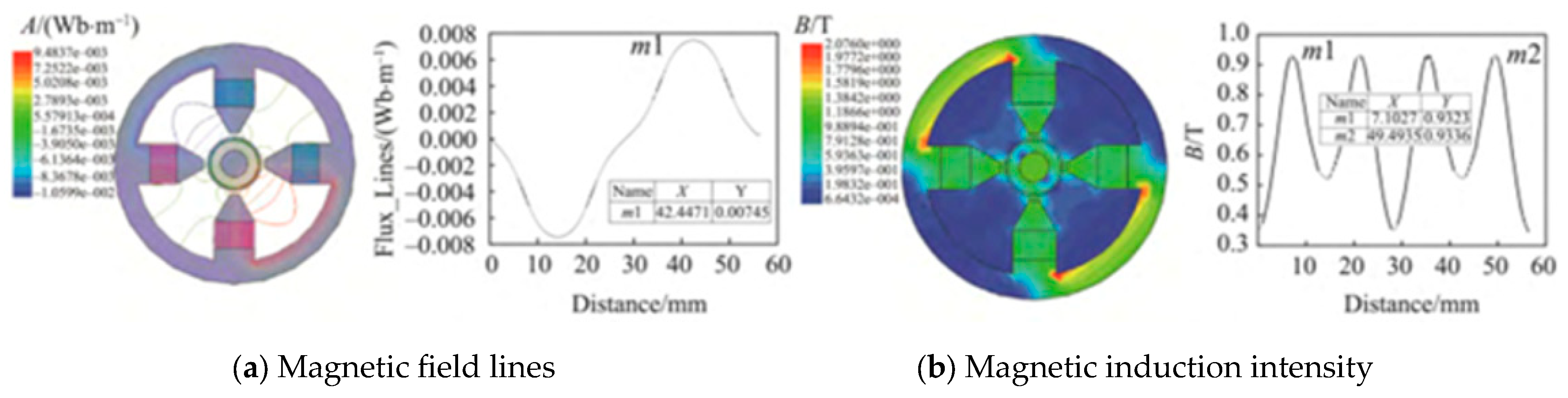
In the formula, is the magnetic flux, unit wb; B is the magnetic induction intensity, unit T; and S is the grinding area in the direction of perpendicular magnetic induction intensity, unit mm2. According to Formula (2), is directly proportional to and . The effect of simple magnetic grinding is not significant. In order to improve the efficiency of magnetic grinding, a 10 mm spherical auxiliary magnetic pole is added inside the bent pipe of the aircraft engine to increase the magnetic flux.
Figure 3 shows the simulated cloud map and distribution curve of magnetic field strength after adding auxiliary magnetic poles. As shown in
Figure 4, after adding the auxiliary magnetic pole, a magnetic circuit is formed between the internal auxiliary magnetic pole and the external magnetic pole, and the magnetic field is significantly concentrated in the grinding area. The magnetic flux and magnetic field strength are greatly increased, and the maximum magnetic flux increases from 0.0028 Wb/m
2 to 0.00746 Wb/m
2. The maximum magnetic induction intensity reaches 0.934 T, and the effective grinding area increases. The direction of magnetic induction intensity is close to perpendicular to the grinding area on the inner surface of the bent pipe. Adding auxiliary magnetic poles increases the magnetic grinding pressure of the magnetic particle brush on the inner surface of the bent pipe of the aircraft engine, increases the amount of magnetic grinding, and improves the efficiency of magnetic grinding [
4,
18,
19].
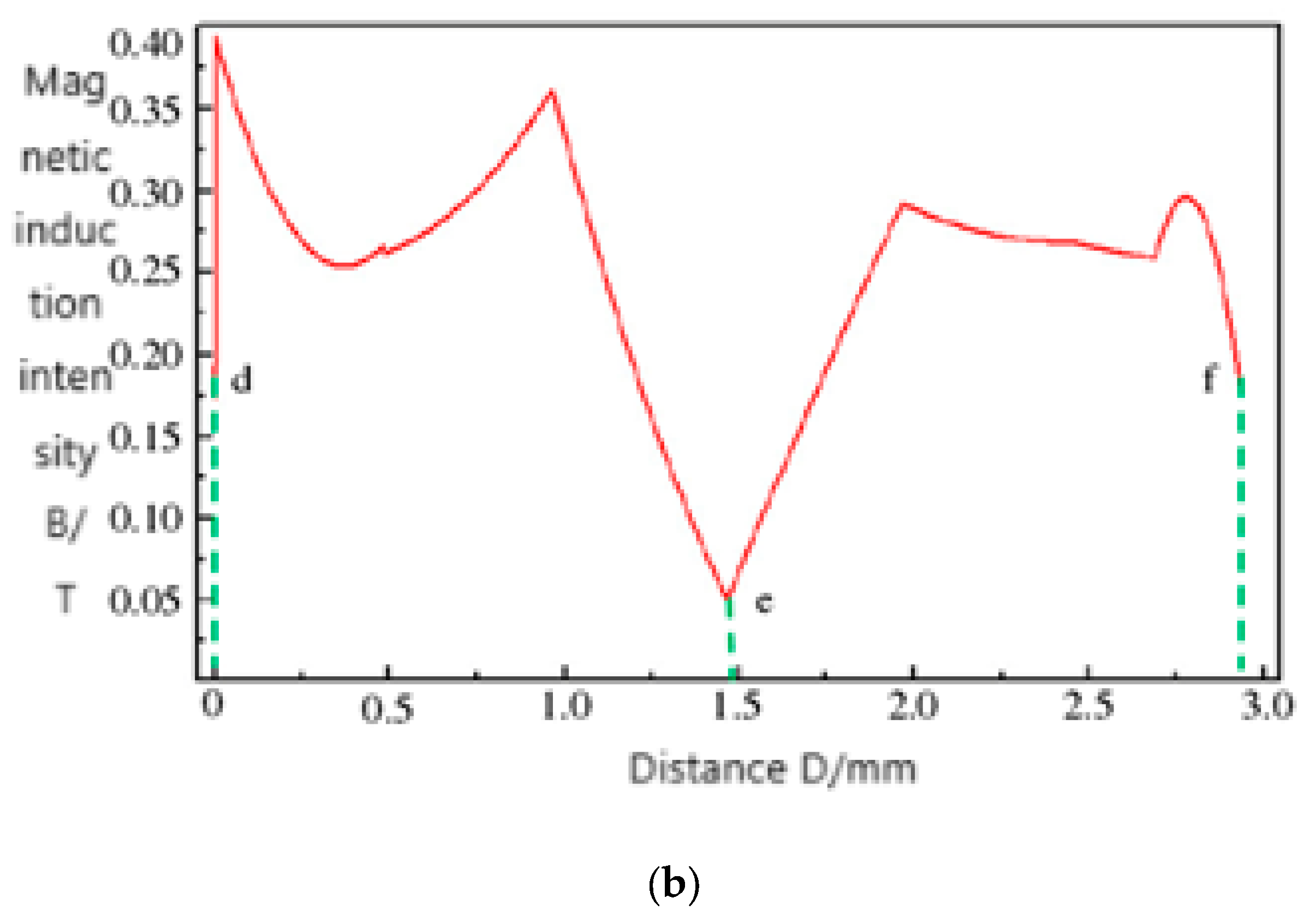
The spherical auxiliary magnetic pole used for magnetic grinding processing of the inner surface of the aircraft engine bent pipe is optimized with intersecting rectangular ring grooves, as shown in
Figure 4. The slot position is along the interface between the N and S poles of the spherical auxiliary magnetic pole and vertically bisects the interface between the N and S poles. The slot width and depth dimensions are the same. The edge of the groove has a high magnetic field strength, while the bottom of the groove has the weakest magnetic field strength, forming an uneven magnetic field and generating magnetic field gradient changes, as shown in
Figure 5. Add auxiliary lines and observe the variation of magnetic induction intensity along the d-e-f direction of the groove edge, as shown in
Figure 5b, represented by redlines.
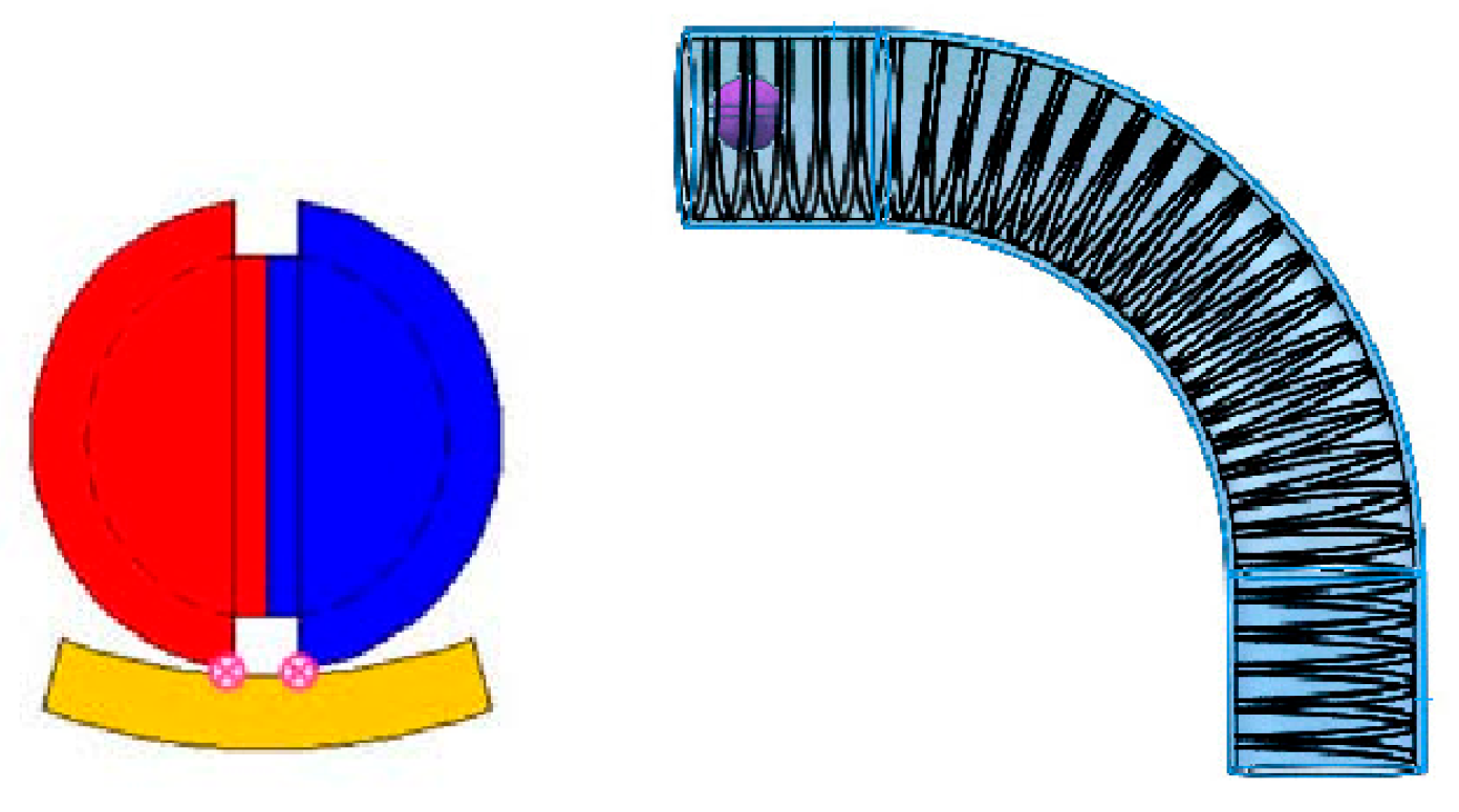
As shown in
Figure 6, the spherical slotted auxiliary magnetic pole dynamically updates and adsorbs magnetic abrasive particles. The magnetic abrasive particle cluster grinds the inner surface of the aircraft engine bent pipe at two or four points, forming a complex and dense multi-helix coupled grinding trajectory with uniform grinding. At the same time, the number of abrasive particles participating in magnetic grinding increases, and the magnetic grinding frequency of the magnetic abrasive particle cluster on the inner wall of the bent pipe increases [
5,
20,
21].
4. Evaluation Method for Optimization Effect of Magnetic Grinding Device
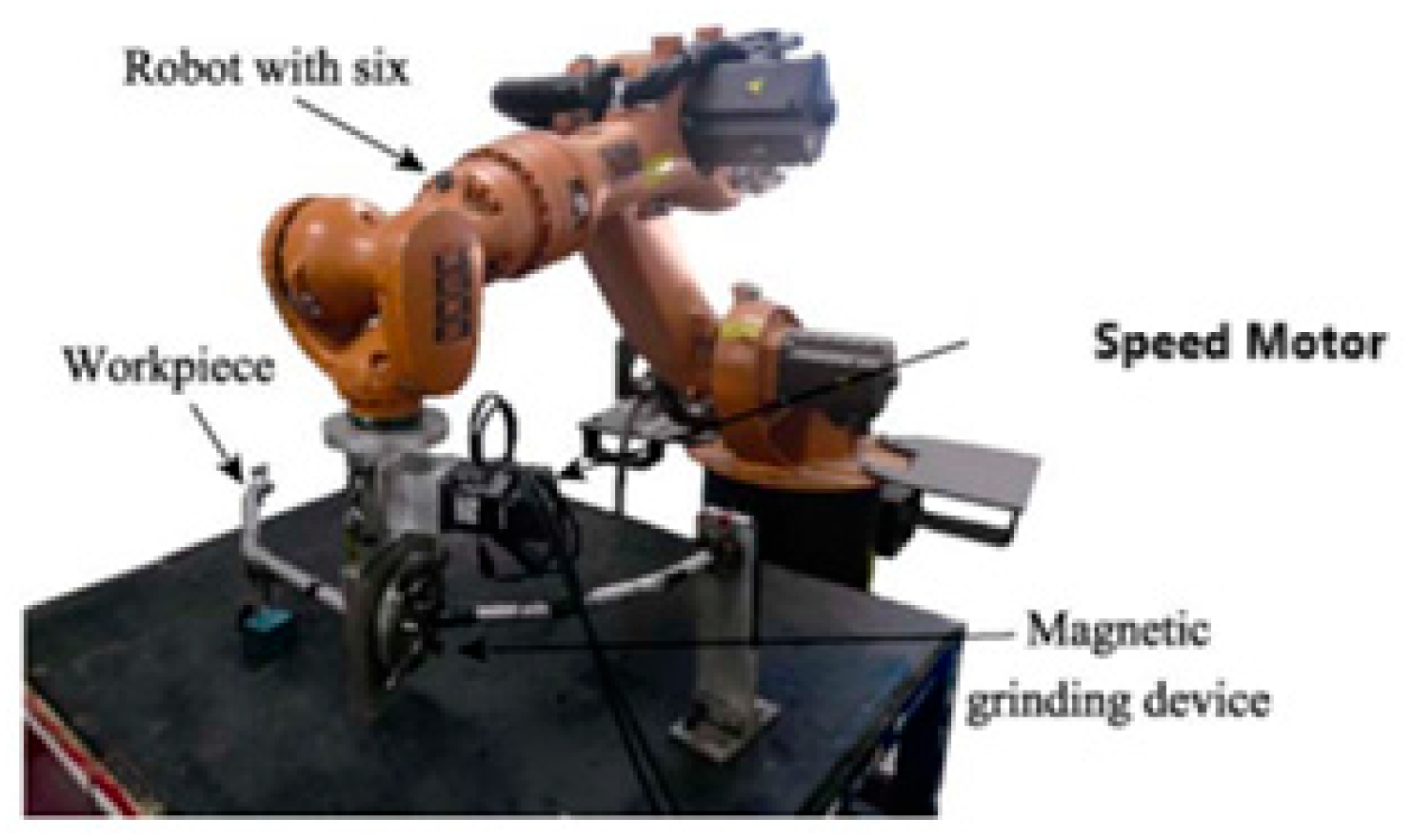
Using an experimental device based on a six-degree-of-freedom robotic arm for magnetic particle grinding of the inner surface of bent pipes, a stylus surface roughness measuring instrument, a super-depth 3D electron microscope, a precision electronic balance, a microhardness tester, etc., to study the effect of optimal magnetic poles on the precision and efficiency of magnetic particle grinding of the inner surface of bent pipes in aircraft engines [
4,
22,
23].
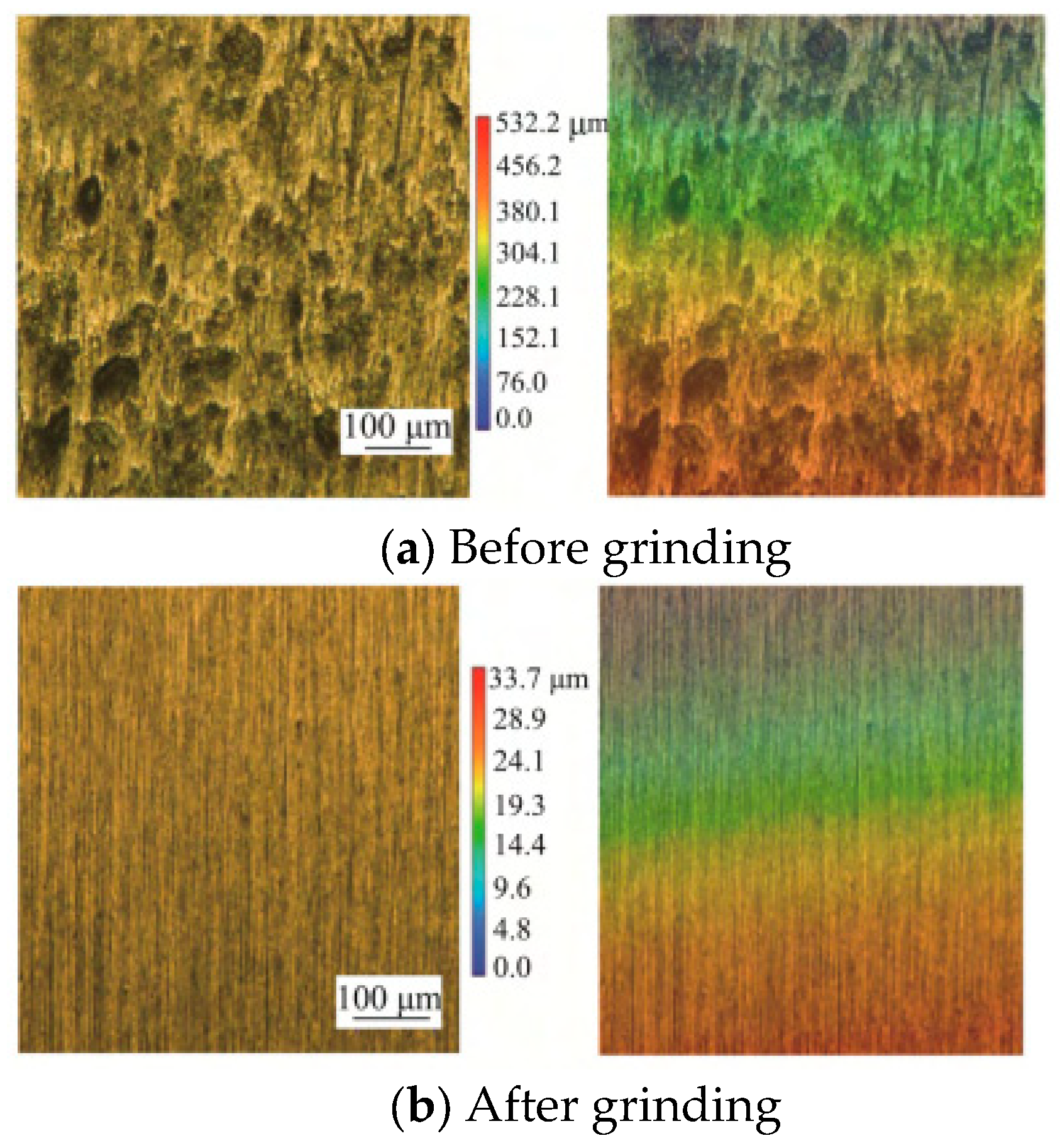
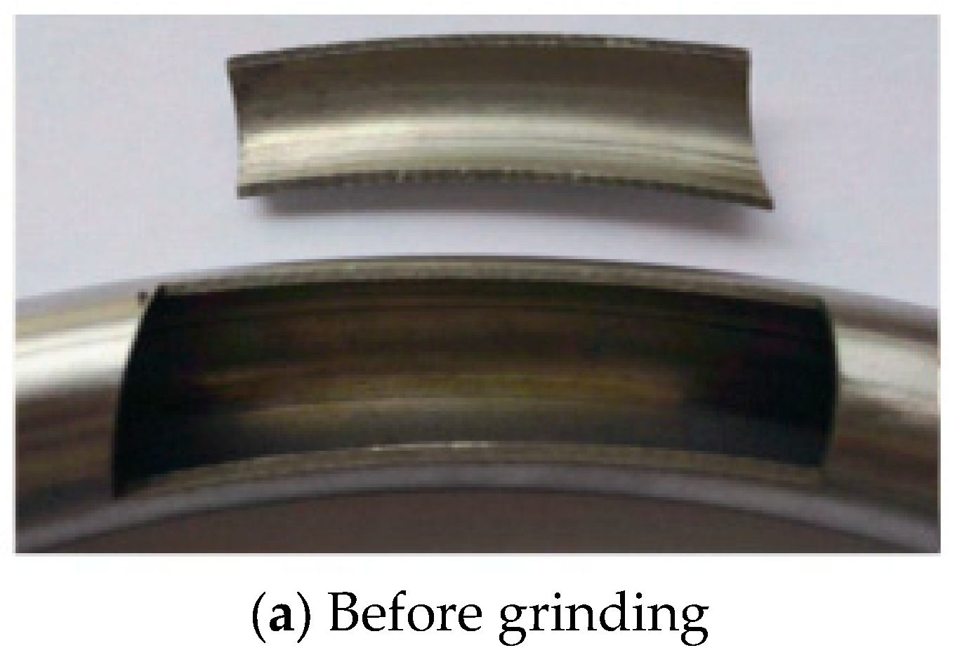
Observe the surface morphology of the aircraft engine bend before and after grinding using a super-depth 3D electron microscope, as shown in
Figure 7.
Figure 8 shows the comparison of surface roughness values of the inner surface of the aircraft engine bent pipe before and after grinding measured by a roughness meter, and From
Figure 7a,
Figure 8a, and
Figure 9a, it can be seen that there are internal surface defects, such as wrinkles and small cracks on the inner surface of the bent pipe without magnetic grinding.
Figure 10 shows the comparison of the inner surface of the aircraft engine bent pipe before and after magnetic grinding [
4,
6,
24].These defects are caused by the cold bending process adopted by the aircraft engine sheet metal factory [
4,
25,
26]. Due to the optimal selection of magnetic poles, as shown in
Figure 7b,
Figure 8b, and
Figure 9b, the surface texture of the inner surface of the aircraft engine bent tube after magnetic grinding is relatively refined and uniform, and the surface roughness value has decreased from 1.34 μm to 0.12 μm, achieving the effect that previously required a long time for magnetic grinding. The magnetic grinding process based on magnetic pole optimization is in the best state, with a uniform magnetic grinding effect and rapid improvement in the surface quality of the bent pipe, which enhances the efficiency of magnetic grinding [
4,
27,
28].
5. Application of Magnetic Grinding for Magnetic Pole Device Optimization in Precision Machining of Inner Surface of Aircraft Engine Bent Pipes
Han Bing, Chen Yan, and others successfully applied servo motors to drive the magnetic pole turntable to rotate, generating a rotating magnetic field that drives the magnetic abrasive particles inside the aircraft engine bend to grind the inner surface of the bend, achieving precise magnetic grinding of the inner surface of the aircraft engine bend [
29,
30]. The magnetic grinding device for the inner surface of the aircraft engine bend is shown in
Figure 10. Use an NdFeB (N35) permanent magnet with a 25-degree tapered permanent pole. Place spherical slotted magnetic poles inside the bent pipe as auxiliary magnetic poles [
6,
31,
32]. Use the JB-8E surface roughness measuring instrument produced by Guangjing Precision Instrument Co., Ltd.from Guangzhou, China, to observe the inner surface of the bent pipe before and after the test.The VHX-500F ultra-depth microscope produced by McDotti (China) Co., Ltd. located in Shanghai, China, was used to observe the microstructure of its inner surface. After magnetic grinding, the inner surface of the bent pipe was very smooth, and defects such as wrinkles and microcracks were completely removed. The inner surface became uniform and fine, improving the accuracy and efficiency of magnetic grinding of the inner surface of the aircraft engine bent pipe [
6,
33,
34].
When precision magnetic grinding the inner surface of aircraft engine bent pipes, adding auxiliary magnetic poles inside the bent pipe can enhance the magnetic induction intensity in the grinding area, increase the grinding pressure, and improve the grinding efficiency [
35,
36,
37]. However, after adding auxiliary magnetic poles, the rigidity of the magnetic particle brush composed of magnetic abrasive particles increases, resulting in a single movement trajectory of individual magnetic abrasive particles, which can easily cause deep scratches on the inner surface of the pipe [
38,
39,
40,
41]. Han Bing et al. addressed this issue by increasing the radial rotation motion of auxiliary magnetic poles [
42,
43]. They analyzed the impact of increasing the radial rotation motion of auxiliary magnetic poles on the magnetic grinding quality of the inner surface of aircraft engine bent pipes and conducted precision magnetic grinding verification experiments. The precision magnetic grinding quality of the inner surface of aircraft engine bent pipes was significantly improved [
44,
45,
46].
6. The Development Trend in Precision Magnetic Grinding Magnetic Pole Devices for the Inner Surface of Aircraft Engine Bent Pipes
Since the 1970s and 1980s, researchers have been developing experimental equipment to study the principle of magnetic particle grinding on the inner surface of bent pipes and have conducted extensive research on the main influencing factors such as magnetic field strength, magnet distribution, and the relative motion of workpieces and abrasives on the grinding quality. In recent years, many scholars have applied the theory of magnetic particle grinding to study the influence and optimization of magnetic pole mechanisms on the precision and efficiency of magnetic particle grinding on the inner surface of aircraft engine bent pipes [
47,
48,
49]. The relevant research mainly focuses on the following aspects: In terms of research progress on magnetic gathering devices, the research mainly focuses on finite element simulation of the influence of magnetic pole shape, magnetic pole head taper, and magnetic pole slot on magnetic particle grinding. Heng et al.’s research shows that when the shape of the magnetic pole head is square, the magnetic grinding effect is the best, while Li et al. studied the influence of the taper of magnetic pole heads on the magnetic grinding effect. In addition to studying the appearance and shape of magnetic poles, scholars have studied the method of slotting magnetic poles to improve the efficiency of magnetic particle grinding. Chen Yan et al. numerically simulated the distribution of magnetic induction intensity along the circumference of a disk-shaped magnetic pole with grooves of different shapes. The simulation results showed that when uniformly distributed rectangular grooves were opened along the circumference of the magnetic pole, the peak value of the magnetic induction intensity wave of the magnetic pole was the largest, the valley value was the smallest, and the magnetic field intensity gradient changed the most, which was most suitable for magnetic particle grinding on complex workpiece surfaces. Cui Tonglei et al. used ANSYS simulation software to simulate the magnetic field strength and magnetic field distribution of magnetic poles and compared and analyzed the advantages and disadvantages of end face magnetic poles, slotted magnetic poles, and copper sleeve slotted magnetic poles. In addition, we conducted preliminary research on the changes in magnetic field lines and magnetic induction intensity in the grinding zone, as well as the design of magnetic pole structural parameters, after adding auxiliary magnetic poles using ANSYS 2021 Maxwell software. The slotted magnetic pole exhibits a phenomenon where the magnetic field strength at the bottom of the slot is much greater than that at the edge, which is not conducive to the uniformity of grinding.
The use of the discrete element method to change the state of magnetic fields has been rapidly developed and widely applied internationally. Based on the magnetic pole discretization theory, the original magnetic poles were discretized and optimized, and the magnetic field discretization distribution improved the grinding uniformity. The increased magnetic field strength increased the grinding pressure P and improved the grinding efficiency. However, there have been no reports on the impact of the discrete method based on slotted magnetic poles on the precision and efficiency of magnetic particle grinding. The theory of magnetic pole slotting can be effectively integrated with the discretized magnetic pole method. The magnetic pole slotting method can effectively change the distribution of the magnetic field area, which is beneficial for the renewal of the magnetic particle brush by increasing the magnetic field gradient. However, after slotting, there is a phenomenon where the magnetic field strength at the bottom of the slot is much greater than that at the edge, resulting in a weaker magnetic field at the edge of the slot. The discretized magnetic pole method provides an efficient and precise solution. Therefore, the first key issue to be addressed is establishing a finite element model combining magnetic pole slotting theory and discretized magnetic pole method to study its impact on the accuracy and efficiency of magnetic particle grinding. Based on the mature theory of magnetic particle grinding on the inner surface of bent pipes, a removal model for magnetic particle grinding materials is established to theoretically analyze the mechanism of material removal on the inner surface of bent pipes in aircraft engines. Next, a method for discretizing magnetic poles based on the magnetic pole slotting method is proposed. Solidworks was used to establish a discretized model of magnetic pole slotting, which was imported into ANSYS Maxwell for simulation analysis. The influence of different discretization methods of slotted small magnetic poles with various shapes on the magnetic induction intensity in the magnetic grinding zone was studied, and the optimization of the magnetic pole structure for precision magnetic particle grinding of the inner surface of aircraft engine bent pipes was carried out. This experimental study on optimizing slotted discrete magnetic poles adopts magnetic particle brush morphology verification experiments to clarify the influence mechanism of different discretization methods based on slotted discrete magnetic poles on the magnetic induction intensity in the magnetic grinding zone. The influence of optimal slotted discrete magnetic poles on the precision and efficiency of magnetic particle grinding on the inner surface of aircraft engine bent pipes was studied using an experimental device for magnetic particle grinding of bent pipes based on a six-degree-of-freedom robotic arm, a stylus surface roughness measuring instrument, a super-depth 3D electron microscope, a precision electronic balance, and a microhardness tester. The designed magnetic particle brush morphology verification experiment simplifies the verification of magnetic field simulation to achieve the optimization design verification experiment of the magnetic pole structure and also simplifies the analysis of magnetic induction intensity and magnetic field distribution before and after magnetic pole optimization through experiments [
50].
7. Conclusions
In summary, (1) from the perspective of research content, research mainly focuses on finite element simulation of magnetic pole shape, magnetic pole head taper, and the influence of magnetic pole slotting on the magnetic field. However, there is a lack of systematic research on modeling and improving the uniformity of magnetic particle grinding for slotted discretized magnetic poles. Experimental verification research on modeling and optimization of slotted discretized magnetic poles is especially rare. (2) From the perspective of research methods, the study of magnetic particle grinding on the inner surface of aircraft engine bent pipes often uses finite element models, orthogonal methods, and response surface methods for analysis. The accuracy and efficiency of magnetic particle grinding are not high, and there is no report on using discrete element theory modeling based on magnetic pole slotting to study the effect of optimizing magnetic pole structure on magnetic particle grinding.
To address the issue of low precision and efficiency in magnetic grinding, the principle of precision magnetic grinding of the inner surface of aircraft engine bent pipes is studied. Based on the discrete element optimization theory of slotted magnetic pole structure, a discretized finite element model is established, and a magnetic particle brush morphology verification experiment is designed. Through a combination of experiments and simulations, the influence of the discrete element magnetic pole distribution based on slotted magnetic pole structure on magnetic particle grinding is explored. These studies are not only beneficial for people to understand the process and physical essence of precision magnetic grinding of the inner surface of aircraft engine bent pipes from a deeper and broader perspective but also lay a theoretical foundation for obtaining a fully optimized precision magnetic grinding process. At the same time, they are of great significance for improving the quality of the inner surface of aircraft engine bent pipes and enhancing the performance of China’s aircraft engines. Based on the mature theory of magnetic abrasive machining on the inner surface of curved pipes, a removal model for magnetic abrasive materials on the inner surface of curved pipes for aircraft engines is established, and the mechanism of material removal on the inner surface of curved pipes for aircraft engines is theoretically analyzed. Next, a method for discretizing magnetic poles based on the magnetic pole slotting method is proposed. Solidworks was used to establish a discretized model of magnetic pole slotting, which was imported into ANSYS Maxwell for simulation analysis. The influence of different discretization methods of slotted small magnetic poles with various shapes on the magnetic induction intensity in the magnetic grinding zone was studied, and the optimization of magnetic pole structure for precision magnetic grinding of the inner surface of aircraft engine bent pipes was carried out. This experimental study on the optimization of slotted discrete magnetic poles adopts magnetic particle brush morphology verification experiments to clarify the influence mechanism of different discretization methods based on slotted discrete magnetic poles on the magnetic induction intensity in the magnetic grinding zone. The designed magnetic particle brush morphology verification experiment not only simplifies the verification of magnetic field simulation to achieve the optimization design verification experiment of magnetic pole structure but also simplifies the analysis of magnetic induction intensity and magnetic field distribution before and after magnetic pole optimization through experiments.
The research plan for precise modeling and prediction of precision magnetic particle grinding based on discrete modeling of slotted magnetic poles is feasible in terms of ideas and experimental operability. In addition, ANSYS Maxwell is a world-renowned finite element software for low-frequency electromagnetic fields, with interfaces for third-party modeling software, laying the foundation for the integration of magnetic pole slotting theory and discretized magnetic pole method. Establishing a three-dimensional discrete finite element model based on slotted magnetic poles not only avoids uneven grinding caused by weakened edge effects in the magnetic field but also reveals the influence of the discrete polar arrangement of slotted magnetic poles on the precision and efficiency of magnetic particle grinding on the inner surface of aircraft engine bent pipes.


