Article

Study on the Influence of Reynolds Number on Heat Exchange Performance and Nusselt Number of Spray Coil Heat Exchanger

1
College of New Energy Engineering, Jiuquan Vocational Technical College, Jiuquan 735000, China
2
School of Energy and Power Engineering, Lanzhou University of Technology, Lanzhou 730050, China
*
Author to whom correspondence should be addressed.
Processes 2025, 13(2), 588; https://doi.org/10.3390/pr13020588
Submission received: 9 December 2024 / Revised: 10 February 2025 / Accepted: 14 February 2025 / Published: 19 February 2025
(This article belongs to the Special Issue Research on Biomass Energy and Resource Utilization Technology)

Abstract

:
Biomass clean energy is widely used as an alternative to fossil fuels due to its advantages of low carbon emissions, cleanliness, and renewability. Biomass fuel exchangers are important equipment for heat exchange between air and exhaust gasses after biomass combustion, and the air flow rate and structural characteristics of the exchanger have a significant impact on the heat transfer performance. In order to investigate the effect of Reynolds number on the heat transfer performance of the exchanger when air flows through, a serpentine tube heat exchange test bench was constructed, and numerical calculations were performed using the Realizable k-ε turbulence model for the entire channel. By changing the diameter and pitch of the serpentine tube, the effects of geometric parameters on the heat transfer performance were studied, and the flow characteristics of exhaust gasses and air inside the exchanger under various operating conditions were deduced. Subsequently, experimental validation was conducted by referring to the boundary conditions of numerical calculations, obtaining corresponding test data, and comparing the numerical and experimental results, showing that the errors in various physical quantities were within 5%. Through comprehensive analysis of the data, it was found that when the serpentine tube diameter is 80 mm and pitch is 300 mm, the Nusselt number (Nu) increased most significantly with Reynolds number (Re) by 25.17%, indicating the best heat transfer performance. Additionally, reducing tube diameter, increasing serpentine tube pitch, enlarging air-inlet flow velocity can enhance Re, increase fluid disturbance, and improve convective heat transfer intensity, thereby increasing Nu and strengthening the heat transfer performance of the serpentine tube exchanger.

1. Introduction

Biomass energy is a new type of clean energy. Compared to clean energies, such as wind power, hydropower, and solar energy, biomass is the only type that can be converted into solid, liquid, and gaseous forms, making it a versatile energy source. Through photosynthesis, biomass can convert solar energy into chemical energy and use various organic materials as energy carriers for energy utilization, hence referred to as the fourth type of clean energy [1,2,3]. Its advantages of being low-carbon, clean, renewable, and capable of replacing fossil fuels have led to its rapid application in more than a dozen industries—including mechanical power, energy supply, heating, and chemical engineering. As early as the 1950s, Japan had already developed and utilized biomass energy pellets, along with the research and development of biomass pellet forming equipment and combustion heat exchange devices. Among these, serpentine tube heat exchangers are widely used in various industrial productions, including chemical, light industry, pharmaceuticals, and others due to their advantages of simple structure, ease of operation, and high heat transfer efficiency. Biomass fuel exhaust gasses typically have high temperatures, and using serpentine tube heat exchangers can enhance safety.
The design and use of biomass fuel heat exchangers require consideration of more factors, such as handling ash content and deposits, material corrosion resistance, complex control systems, and higher safety requirements. These challenges necessitate engineers to take comprehensive measures in designing and implementing biomass heat exchange systems to ensure their efficient, reliable, and safe operation. The supply-heating equipment of biomass energy pellet fuel is very common now. Its basic principle involves the full combustion of clean energy biomass pellets in the combustion chamber, releasing a large amount of high-temperature flue gas. This flue gas enters the heat exchanger to heat the air, raising the air temperature to the desired standard for use [4]. This process involves thermodynamic processes such as combustion and heat transfer. Improving the heat exchange performance of the system is beneficial for the development and application of biomass fuel heat exchangers. With the rapid development of computer technology and image display technology, the application of Computational Fluid Dynamics (CFD) for studying the flow characteristics and heat transfer of complex fluid behaviors has become a major research method [5,6]. Fu et al. [7] studied the influence of inflow velocity distribution on the performance of the biomass fuel heat exchanger through numerical calculations, finding that the size and uniformity of the inflow velocity have a significant impact on the temperature field and pressure field of the heat exchanger; Liu et al. [8] studied the influence of jet impact velocity on the heat exchange performance of the biomass fuel heat exchanger, finding that with the increase in jet velocity, the convective heat exchange effect becomes better. In recent years, Chun et al. [9] discussed the influence of fluid inflow velocity on the enthalpy and heat exchange efficiency of paper heat exchangers, finding that temperature heat exchange efficiency and enthalpy are sensitive to inlet velocity. Li et al. [10] used the combination of standard turbulence and VOF multiphase flow mathematical models to solve the heat transfer coefficient of coiled tube heat exchangers with different diameters and compared them with experimental results, with errors within a certain range, indicating that numerical simulation is reliable in evaluating heat exchanger heat transfer and fluidity. Wang et al. [11] studied the simulation of the influence of structural parameters on the heat exchange performance of coiled-tube heat exchangers, finding that the spacing between the coiled tubes, the distance between the tubes, and the outer diameter of the tubes are negatively correlated with the heat transfer coefficient. Lu et al. [12] installed fins on the heat exchanger tubes to enlarge the heat transfer area and enhance the natural convection heat transfer. Zhao et al. [13] studied the influence of spacing on the enhancement of heat transfer and resistance to flow of concave pits, finding that when the streamwise spacing S1 decreases from 1.5 to 0.8, the average comprehensive heat transfer flow resistance increases. Lazova et al. [14] experimentally explored the performance of helical coil heat exchangers operated under subcritical and supercritical conditions by varying fluid mass flow rate and inlet pressure. The results revealed that the mass flow rate of the working fluid has a greater impact on the heat transfer rate. Hua et al. [15] numerically studied the effects of structural parameters such as spacing, thickness, and height of helical fins on the heat transfer and resistance performance of helical finned-tube heat exchangers. They determined the optimal structure of helical finned-tube heat exchangers.
Therefore, significant progress has been made in the thermodynamic study of biomass fuel heat exchangers through the application of numerical simulations. However, past studies have primarily focused on the fluid dynamic performance or surface heat transfer performance within the heat exchanger, neglecting to couple the analysis of heat exchange performance with flow characteristics. This study will focus on the entire heat exchange system under the conditions of smoke generation after biomass pellet combustion [16]. Firstly, a testing device for biomass fuel heat exchangers was constructed to conduct on-site experiments under specific operating conditions. Subsequently, by creating a numerical model, a detailed analysis of the relationship between the structural and environmental parameters of the serpentine tube heat exchanger and heat transfer performance and flow characteristics was conducted. In particular, the impact of serpentiform tube diameter and spacing of the protruding part of the serpentine tube on the heat exchanger’s performance was scrutinized [17]. By integrating flow parameters and thermodynamic parameters, a comprehensive evaluation of the performance of the heat exchange system derived from biomass pellet combustion was carried out. This work provides insights for clean heating in large-scale industries and agricultural settings in cold regions.

2. Materials and Methods

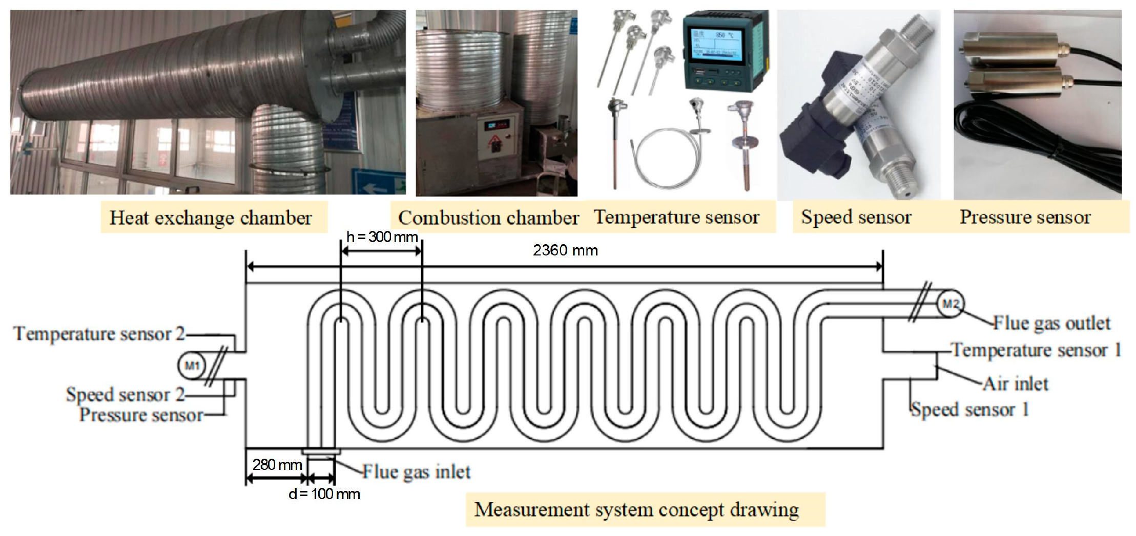
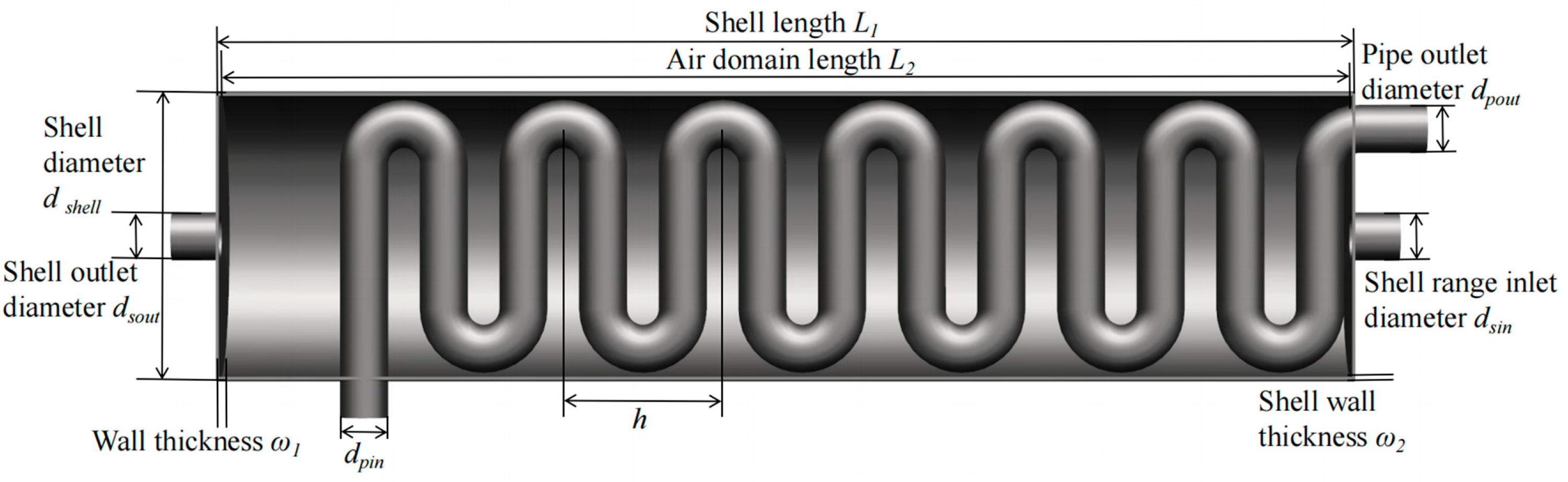
2.1. Geometric Model and Experimental Device

To verify the reliability of the numerical analysis, an experimental platform consistent with the parameters of the biomass fuel heat exchanger was set up. Figure 1 shows a schematic diagram of the combustion chamber, the model of the heat exchanger test stand, and the positions of the test equipment. Temperature and velocity sensors were installed at the inlet and outlet of both the flue gas pipeline and air ducts. Figure 1 specifically indicates the description of the location for the air-inlet and -outlet sensors only. These sensors are utilized to monitor the thermodynamic parameters of air and flue gas during the experimental process, providing data for the reliability analysis of numerical calculations. The inlet and outlet pipe diameters of the shell and serpentiform tube are the same.
The geometric parameters of the heat exchanger have a significant impact on the heat transfer performance. This study focuses on exploring the potential correlation between the diameter of the serpentine tubes and the spacing of the protruding part of the serpentine tubes with heat transfer performance. The serpentiform tube diameters d are set at 80, 90, 100, 110, and 120 mm, while the serpentiform tube protrusion spacings h are set at 290, 300, 310, 320, and 330 mm. Figure 2 illustrates the geometric model along with the remaining structural parameters. This article primarily employs numerical simulations to investigate the impact of serpentiform tube diameter and spacing of the protruding part of the serpentine tube on heat transfer efficiency.

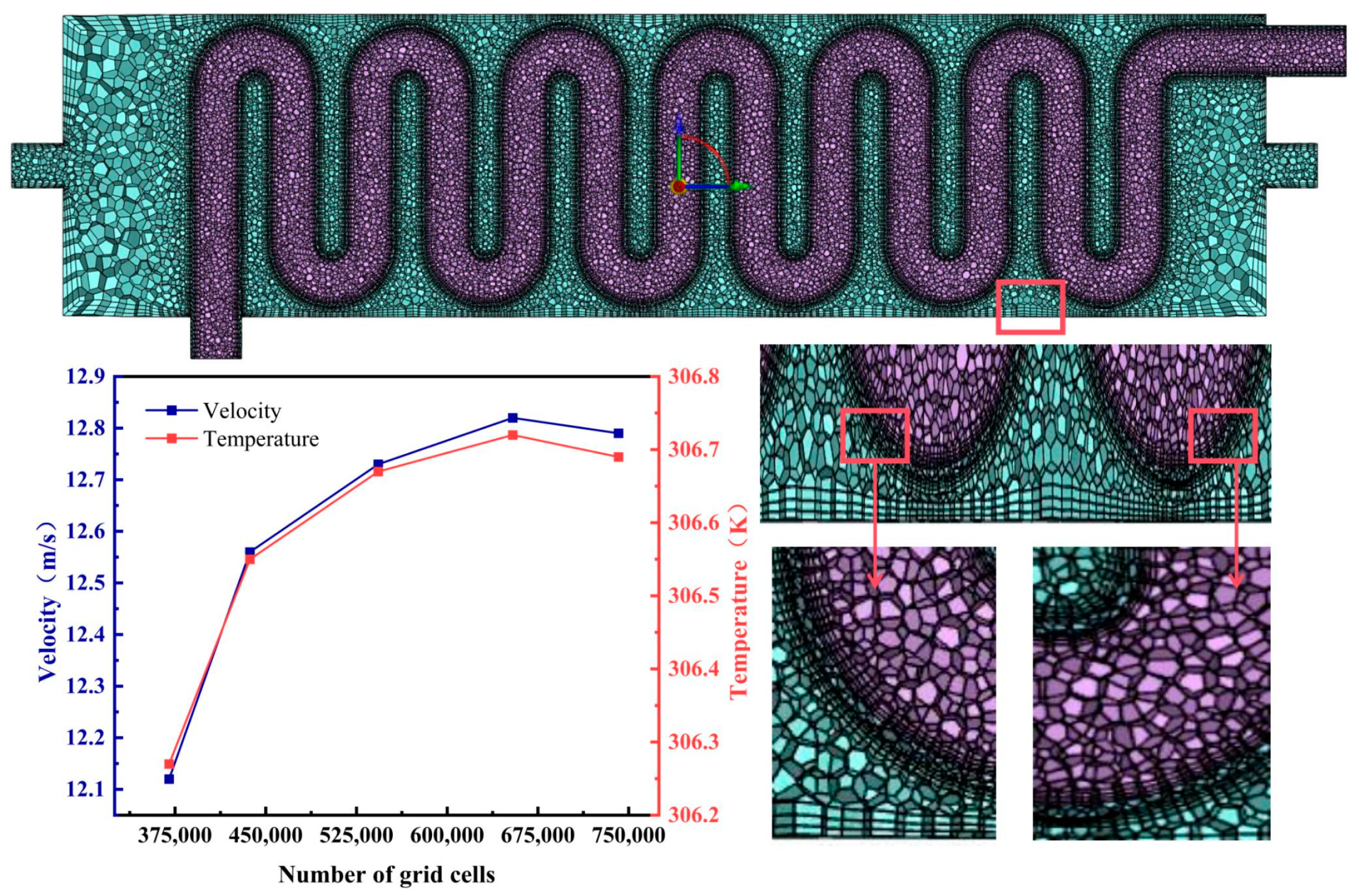
2.2. Mesh Generation and Independence Testing

After constructing the geometric model, spatial discretization of the continuous model with a mesh is necessary to numerically solve the research problem. Considering the serpentine coil’s multiple continuous curved surfaces and complex structure, tetrahedral grids are more efficient, offering higher grid quality. Therefore, this study applied tetrahedral grids to the air, flue gas, and solid domains, refining them at the bend regions to control aspect ratios close to 1 for enhanced computational accuracy. The temperature and velocity boundary conditions are set at the air and flue gas inlet, and the pressure outlet conditions are selected at the outlet. In this study, tetrahedral meshing was applied to the air domain, flue gas domain, and solid domain. Boundary layer meshing was established on the shell surface to precisely capture flow and heat transfer conditions and mitigate the effects of the boundary layer [18,19,20,21]. The meshed model is illustrated in Figure 3. To ensure grid independence of the solution, we chose a heat exchanger model with dimensions serpentine tube diameter d = 100 mm, serpentine tube protrusion spacing h = 300 mm, serpentine tube length L1 = 2360 mm, and velocity u = 16 m/s. We conducted numerical calculations on five sets of grid models of the heat exchanger and verified the independence of the computational results. The grid models and grid-independent data are shown in Figure 3. With the premise of ensuring the precision and reliability of the computational results, using grid models with fewer grids allows for the rational allocation of computational resources. In this study, when the grid number was around 650,000, the outlet temperature and rotation speed reached equilibrium (with the fluctuation range of physical quantities not exceeding 3%), showing no significant changes. It can be concluded that the numerical results were grid-independent at this point. Therefore, the final determined grid number is approximately 650,000. Numerical simulations of the serpentine heat exchanger were conducted using Fluent 16.0 software with the SIMPLE algorithm. The pressure discretization scheme was set to PRESTO!, while the rest utilized second-order upwind schemes.

2.3. Flow Control Equations and Numerical Models

In the engineering process of the heat exchanger, its internal fluid conforms to the conservation of mass and momentum, and because of the existence of thermodynamic processes, it is necessary to open the energy equation in the numerical calculation, and the energy equation satisfies the law of conservation of heat [22,23,24,25]. Equations (1)–(3) represent the cylindrical coordinate expressions of the mass conservation, momentum conservation, and energy conservation equations under non-equilibrium conditions. Equations (4)–(6) provide the expressions for the mass conservation, momentum conservation, and energy conservation equations under static conditions where both the velocity and external work are zero. In numerical applications, the fluid is treated as an incompressible substance. Among them, ux, uy, and uz represent the velocity components of the fluid, respectively. x, y, and z represent coordinates, Ui is the velocity tensor, ρ is the fluid density, υ is the fluid kinematic viscosity, p is pressure, T represents the temperature, and α represents fluid thermal diffusivity [26,27,28].
1 r r u r r + 1 r u θ θ + u z z = 0
ρ ( u t + u u ) = p + μ 2 u + f
( c p T ) t + ( c p T u ) = ( k T ) + Φ
ρ t = 0
F = 0
d E d t = 0
The biomass fuel heat exchanger studies fluid media, namely flue gas and air, both of which are turbulent flows. Therefore, mathematical modeling employs turbulence models. Several turbulence models are introduced, including the standard k-ε model and RNG model, the RNG (Re-Normalization Group) model is an enhanced turbulence model and belongs to the category of eddy viscosity models. Additionally, the achievable k-ε model is suitable for a wide range of flow types. Therefore, this paper selects the realizable k-ε model [29,30].
As this text concerns a numerical computational analysis of a biomass fuel heat exchanger, the physical property parameters of the material related to fluid flow and temperature have been established. To ensure effective heat exchange, copper has been selected as the material for the heat exchanger tube, while carbon steel has been chosen for the shell range. The system operates under high temperature and pressure, as shown in Table 1. Table 2 displays the physical parameters of the flue gas, while Table 3 shows the physical parameters of the air. Where CP is the specific heat capacity at constant pressure ρ k g .
The serpentine tube heat exchanger designed for biomass fuel features velocity-inlet flue gas and air inlets. It is imperative to define the velocity, pressure, temperature, and turbulence intensity at these inlets. The outlet is configured as a pressure outlet with a pressure setting of 101,325 Pa. The air inlet is designated as a velocity inlet, with the inlet velocity varying from 10 to 20 m/s. The air-inlet temperature is set at 283 K, the high-temperature flue gas inlet temperature is 500 K, and the inlet velocity is 5 m/s. A no-slip velocity boundary condition must be applied to the wall surface of the heat pipe, with the flue gas and air interface acting as the heat transfer surface [33]. Likewise, the smoke and air interface should also function as the heat transfer surface, maintaining a no-slip velocity boundary condition on the wall surface [34,35].

2.4. Experimental Procedure

In this study, experimental verification was conducted using the method of controlling variables. By keeping other inlet conditions constant while varying the air-inlet flow rate, the outlet parameters of the flue gas were measured at different flow rates for analysis and processing. Firstly, all instrument equipment was checked for proper functioning, ensuring secure sealing at all connections without any leaks, and recording environmental conditions during the experiment (room temperature, atmospheric pressure, etc.). Subsequently, based on experimental requirements, the initial temperatures and flow rates of each fluid were set. The experiment was initiated by opening the air and flue gas inlet valves, recording temperature and velocity data every 5 min until the conclusion of the experiment. Following the completion of the experiment, all equipment was shut down to ensure safety.

3. Results and Discussion

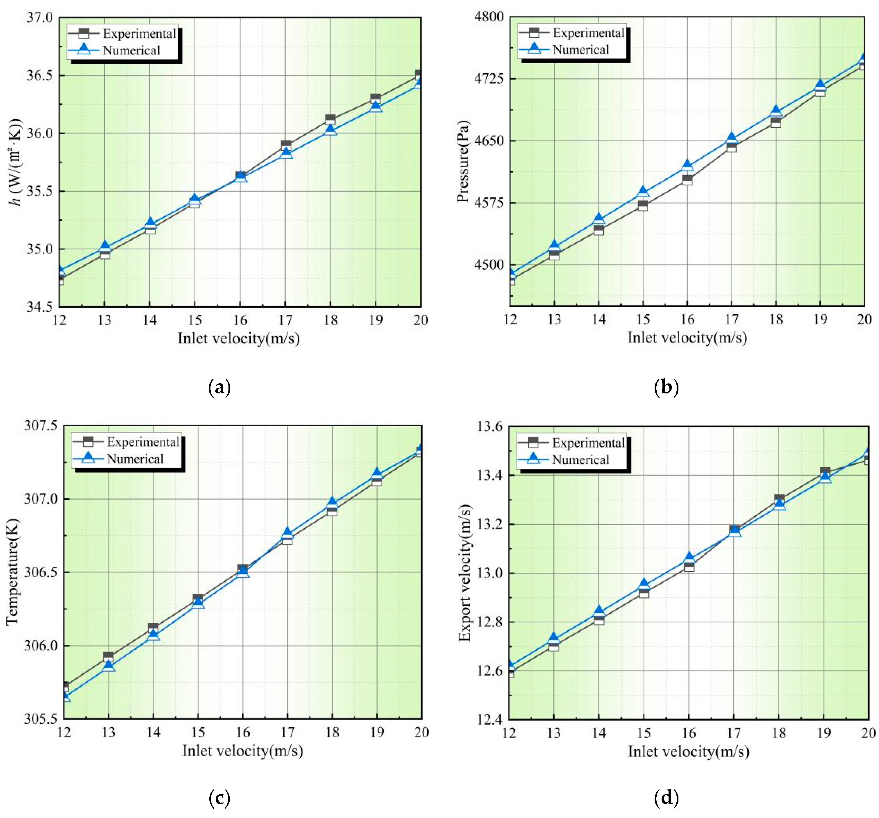
3.1. Reliability Verification of Numerical Results

To validate the reliability of the numerical method, experimental tests were conducted for the conditions with d = 100 mm, h = 300 mm, and u = 16 m/s, and the results were compared with the numerical simulation results under equivalent conditions, as shown in Table 1. The experimental measurements show slightly higher air outlet temperature, velocity, pressure, and convective heat transfer coefficient values compared to the numerical results. This discrepancy is primarily due to the thermal expansion of air. As the heated air expands inside the shell, it leads to an increase in outlet pressure, flow velocity, and other physical quantities. The numerical simulations overlook the thermal expansivity of air, causing the numerical results to be slightly lower than the experimental outcomes. Since the thermal expansivity coefficient of air is very small, approximately 0.00367 K−1, it can be neglected.
Figure 4 illustrates the relationship between various physical quantities and the air-inlet velocity in both experimental and numerical simulations, showing that these quantities increase with higher velocities. The growth trends in experimental and numerical results are quite consistent. Regarding the temperature-inlet velocity relationship, before 16.5 m/s, experimental temperatures were slightly higher than the numerical values but decreased afterward. This is mainly due to heat losses during the experimental process, leading to lower experimentally measured temperatures compared to the numerical results, especially noticeable at higher inlet velocities. As the inlet velocity continues to increase, heat transfer becomes more efficient, resulting in greater heat loss. Table 4 shows the relative errors of the experimental and numerical simulations. Consequently, after 16.5 m/s, the numerical temperatures exceed the experimentally measured temperatures. In conclusion, the errors between experimental and numerical results at each velocity are within 5%, indicating the reliability of these numerical results.
Furthermore, Lazova et al. [14] explored the performance of a helical-coil heat exchanger operating under subcritical and supercritical conditions by varying fluid mass flow rate and inlet pressure. The study revealed that the mass flow rate of the working fluid has a significant impact on the heat transfer rate, with better heat transfer efficiency observed at higher mass flow rates. In this study, the experimental and numerical alterations were based on changing the air-inlet velocity, where higher velocity implies larger mass flow rates, aligning with the findings of Lazova et al.’s experiments.

3.2. Analysis of Heat Transfer Performance in Shell of Heat Exchanger

The Reynolds number (Re) is a dimensionless coefficient used to characterize the relative magnitude of inertial forces to viscous forces in fluid flow, as shown in Equation (7) [28,29,30,31]. Here, L represents the characteristic length of the heat transfer area. At low Reynolds numbers, high viscosity tends to dampen disturbances, while increases in the Reynolds number lead to more prominent fluid disturbances. By analyzing the temperature, velocity, and pressure fields of the flue gas within the range of Reynolds numbers from 48,108 to 102,043, the fluid dynamics and heat transfer characteristics inside the heat exchanger shell side were investigated based on varying Reynolds number values. As the flue gas inlet temperature and velocity remain constant with minimal variation during the heat transfer process, the experiment and numerical investigation focused on the impact of varying air-inlet flow rates on heat transfer. The changes in air-inlet flow rates lead to variations in the air parameters within the shell.
R e = ρ u L μ
Figure 5 shows the contour plots of the temperature distribution at different Reynolds numbers for the axial and radial sections of the heat exchanger with dpin = 100 mm, h = 300 mm. The sections selected are at shell lengths of 450 mm, 1050 mm, and 1650 mm, with the leftmost side serving as the reference point. From Figure 5, it can be observed that in the initial stages, due to the initial combustion, the flue gas exhibits higher thermal effects, reflected in high-temperature magnitudes. As the flue gas flows through the heat exchange tube walls and exchanges heat with the ambient gasses, the flue gas temperature gradually decreases along the flow path, while the air temperature gradually increases. In certain details of heat transfer, the tube wall acts as an important medium for heat conduction, exhibiting heat concentration behavior. Therefore, the air temperature around the tube wall of the serpentine is higher than in other regions.
At the air-outlet pipe, the temperature decreases continuously from the central line towards the pipe wall, mainly because as the air flows from the shell side towards the outlet, the flow cross-section decreases, compressing and heating the air upstream as it constantly converges towards the centerline of the outlet pipe. This results in higher air temperatures at the centerline of the outlet pipe compared to the pipe wall.
Under different Reynolds numbers, there is no significant variation in the flue gas temperature within the serpentine and the inlet air temperature on the right side of the shell. However, the outlet air temperature on the left side of the shell decreases with an increase in Re. For Re of 48,108, 72,162, and 102,043, the outlet air temperatures on the left side are 316.64 K, 309.14 K, and 302.18 K, respectively. This reduction is primarily due to the shortening of the heat transfer time caused by high flow rates, where this “short-time heat transfer” effect masks the enhanced heat transfer due to turbulence. Therefore, selecting an appropriate air Re significantly affects the heat transfer performance of the heat exchanger. Based on the findings from the study, it is recommended not to excessively increase fluid velocity when designing heat exchanger systems. Instead, leverage the full potential of fluid heat transfer, considering both flow time and speed comprehensively, to achieve efficient energy utilization.

3.3. Analysis of Flow Performance in Shell of Heat Exchanger

Figure 6 illustrates the contour plots of velocity distribution for axial and radial sections of the heat exchanger with dpin = 100 mm, h = 300 mm at various Reynolds numbers. It can be observed from Figure 6 that as the flue gas enters the serpentine, the velocity remains constant due to a constant heat flux. There is no significant change in velocity from the inlet to the outlet, and the distribution is relatively uniform. Meanwhile, as air flows through the entire shell side, the smaller cross-section at the inlet and outlet results in a larger cross-section for the shell side, leading to an air velocity distribution of “higher at both ends, lower in the middle”.
In finer details of air flow, the serpentine near the air inlet on the right side of the shell first comes into contact with the air, hindering some airflow and resulting in higher air velocities around this part compared to other regions.
Under different Reynolds numbers, the air velocities on the left and right sides of the shell and their differences increase with higher Reynolds numbers. For the Re of 48,108, 72,162, and 102,043, the velocity differences at the inlet and outlet are 2.04 m/s, 3.07 m/s, and 4.1 m/s, respectively. The main reason for this is that with an increase in Re, the air more vigorously sweeps the serpentine and the wall surfaces, leading to higher turbulence intensity. This weakens the air viscosity, reduces friction between the air and serpentine walls, increases airflow kinetic energy, and consequently enlarges the velocity difference at the inlet and outlet. Therefore, selecting an appropriate air Reynolds number significantly impacts the distribution of air in the shell side. Based on the findings from the study, it is recommended to increase fluid velocity when designing heat exchanger systems to promote a more extensive fluid distribution, enhance the fluid’s turbulent energy, and achieve a uniform heat transfer effect efficiently.

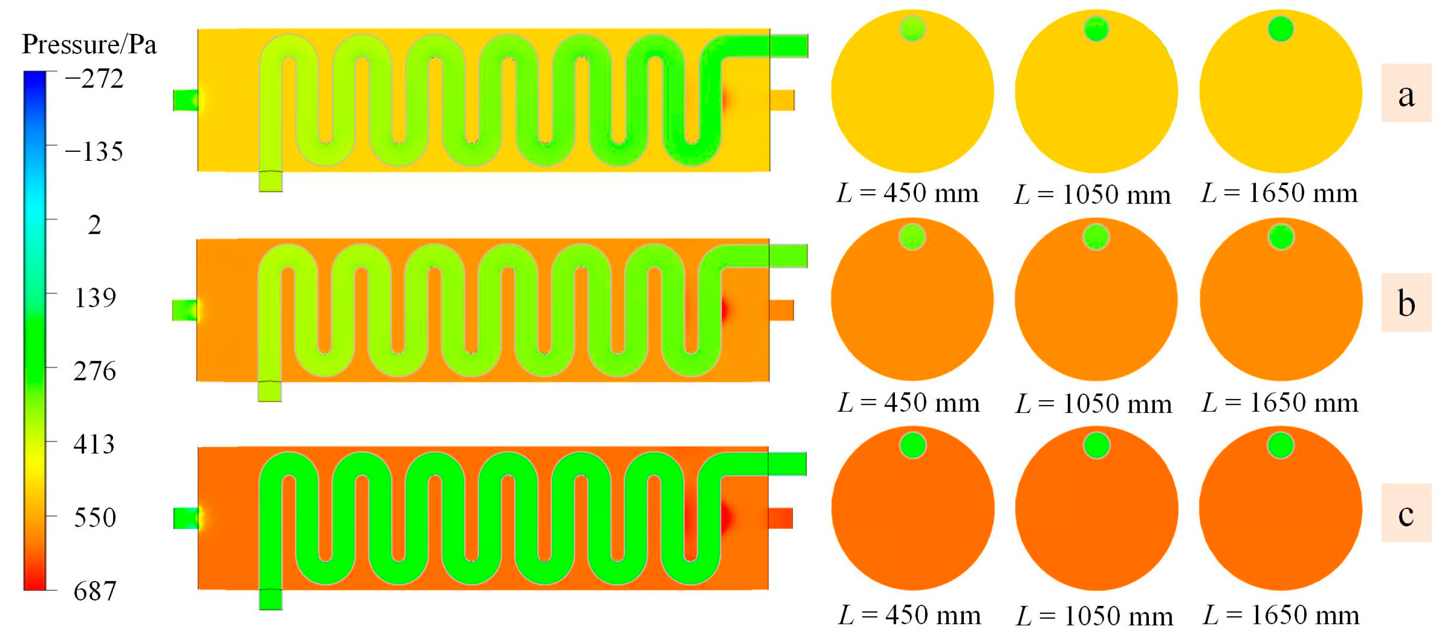
3.4. Analysis of Pressure Performance in Shell of Heat Exchanger

Figure 7 illustrates the contour plots of pressure distribution for axial and radial sections of the heat exchanger with dpin = 100 mm, h = 300 mm at different Re. It can be observed from Figure 7 that as the flue gas flows through the serpentine, it exchanges heat with the external air through the heat exchange tube walls. Due to the high thermal expansion and contraction effects of gasses, the temperature of the high-temperature flue gas decreases continuously after transferring heat to the ambient air at normal temperature. The contraction of the flue gas causes the pressure to gradually decrease along the flow path, while the absorbed air temperature rises, leading to an increase in pressure due to air expansion.
In some details of air pressure changes, the serpentine on the right side near the inlet obstructs the inflow of some air, resulting in an increase in external pressure around that section of the serpentine.
Under different Re, the air pressure in the shell side increases with higher Reynolds numbers. Additionally, the pressure gradient at the interface between the shell side and the air outlet pipe also increases continuously. For Reynolds numbers of 48,108, 72,162, and 102,043, the relative air pressures at the left outlet end are 187 Pa, 216 Pa, and 248 Pa, respectively. The primary reason for this is the sharp decrease in cross-section at the junction between the shell side and the air outlet pipe, causing air surrounding the area to form eddies. This leads to the separation of the air boundary layer along the shell wall, subsequently increasing the air pressure gradient.
Therefore, selecting an appropriate Reynolds number significantly impacts the variation in the air pressure gradient on the shell side. Based on the conclusions of this study, it is recommended to increase fluid velocity when designing heat exchanger systems to enlarge the eddy-producing region, enhance disturbance in the boundary layer, thin out the boundary layer, and improve heat transfer efficiency.

3.5. Effect of Shell and Tube Diameter Parameters on Heat Transfer

The ratio of the heat transfer by air convection to the heat transfer by conduction at the outer wall of a serpentine tube can be obtained through the following Nu calculation formula.
N u = h L k
Here, hc is the convective heat transfer coefficient at the interface between the serpentine tube and air, L is the characteristic length of the heat exchanger, and k is the thermal conductivity of air. Nu is the ratio of convective heat transfer to conductive heat transfer across the boundary, reflecting their relative magnitudes. Since convective heat transfer predominates during the heat exchange process, a higher Nu indicates stronger convective heat transfer.
Figure 8 shows the curve of the variation in Nu with air-inlet flow velocity for different tube diameters. It can be observed from the graph that, at the same tube diameter, Nu increases with increasing air velocity. This is because the increase in velocity leads to an increase in the hc, and since Nu is directly proportional to h, Nu also increases with higher air flow rates. Specifically, for d = 100 mm, with the flow velocity increased by 10 m/s, Nu increased by 23.43%.
At the same flow velocity, Nu decreases with an increase in tube diameter. The main reason for this phenomenon is that the temperature and velocity of the high-temperature exhaust gasses flowing through the serpentine tubes remain constant. With a larger tube diameter, the heat exchange surface area increases, leading to a decrease in the heat transfer rate per unit area, thereby reducing the hc and subsequently decreasing Nu. Specifically, for u = 16 m/s, with the tube diameter increasing by 50 mm, Nu decreased by 27.9%.
Therefore, designing appropriate heat exchange tube diameters and air flow velocities has a significant impact on increasing Nu and enhancing convective heat transfer efficiency.

3.6. Effect of Serpentine Bump Spacing on Heat Transfer

Figure 9 illustrates the bar chart displaying the variation in Nu with air-inlet flow velocity for different serpentine protrusion spacings. From the graph, it can be seen that at the same spacing, Nu increases as the air flow velocity increases. The reasons are consistent with those described in Section 3.5. The increase in velocity leads to a higher hc, consequently increasing Nu. Specifically, for h = 330 mm, with the flow velocity increasing by 10 m/s, Nu increased by 23.39%.
At the same flow velocity, Nu increases with an increase in spacing. The primary reason for this trend is that larger serpentine protrusion spacing results in a wider distribution of heat exchange surfaces inside the shell, leading to more thorough and uniform heat transfer. This expansion enhances the hc of the air, thereby increasing Nu. For u = 20 m/s, with the spacing increased by 40 mm, Nu increased by 2.83%.
Therefore, designing appropriate serpentine protrusion spacing is crucial for increasing Nu and expanding the heat transfer area.

3.7. Influence of Re on Nu

Figure 10 depicts the relationship between Re and Nu for different operating conditions. It can be observed from the graph that Nu increases with the growth of Re across all conditions. Specifically, when d = 80 mm and h = 300 mm, the highest percentage increase in Nu with respect to Re is 25.17%. Re reflects the relative magnitude of inertial forces to viscous forces. The fluids designed in both experimental and numerical simulations have relatively high Re, indicating turbulent flow where inertia dominates over viscosity. In such scenarios, the fluid experiences greater inertia effects, leading to irregular and fluctuating flow patterns, enhancing mixing within the fluid and consequently accelerating heat transfer between fluids, thus improving convective heat transfer effectiveness.
Nu represents the relative strength between convective heat transfer and conductive heat transfer. A higher Nu signifies a greater predominance of convective heat transfer throughout the heat exchanger process. Therefore, one of the significant reasons for increased Nu is the rise in Re, which enhances convective heat transfer strength between fluids. Additionally, the increase in Re results in a thinner fluid boundary layer and larger velocity and temperature gradients, contributing to the enhancement of Nu.
In conclusion, when designing and selecting heat exchangers, it is essential to consider the impact of convective heat transfer on the heat transfer performance of the exchanger. By increasing Re to improve Nu, it is possible to enhance the heat transfer performance of the exchanger.

4. Conclusions

Nu responds to the relative magnitude of convective heat and conduction heat on the heat transfer boundary, and when Nu is large enough, the proportion of convective heat transfer is increased, and the heat transfer inside the heat exchanger is more obvious. In order to improve the heat transfer performance of the biomass fuel heat exchanger, we have conducted a systematic study on the size of the heat exchanger tube diameter, serpentine bump spacing, and the size of the air-inlet flow rate, and the specific conclusions obtained are as follows:
(1)
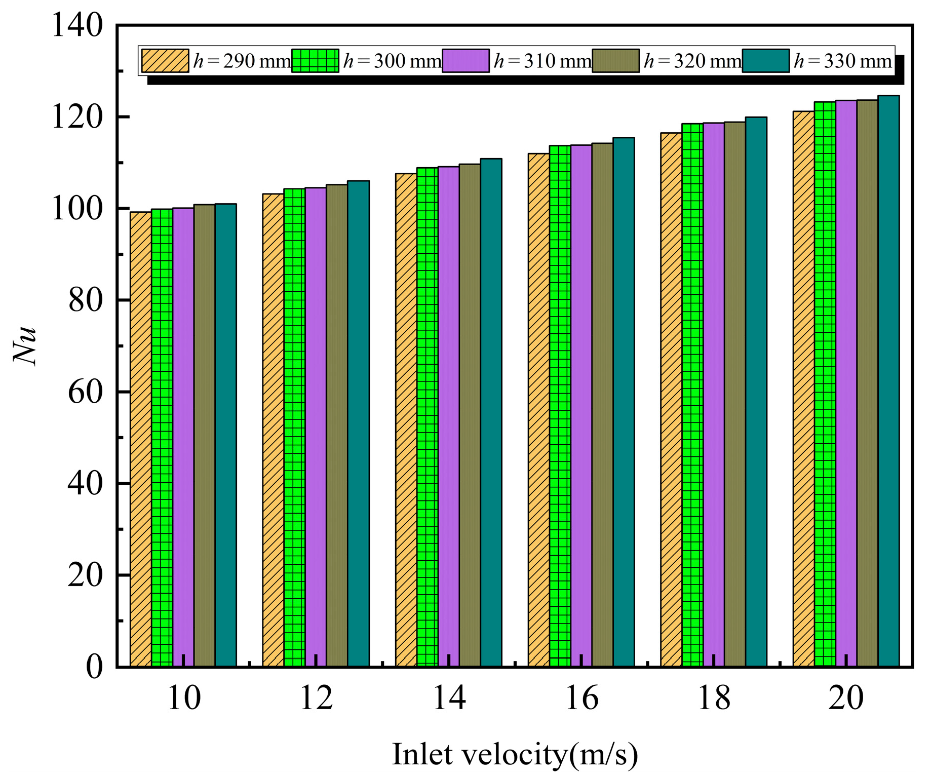
The temperature and velocity on the air-inlet side of the serpentine heat exchanger are lower compared to other regions, forming a heat transfer dead zone. The primary reason for this phenomenon is that the air-inlet side is located at the end of the serpentine tube, where the high-temperature flue gas entering the tube continuously dissipates heat along its path until it reaches the end where the air enters. By that point, the temperature has significantly decreased, resulting in limited heat transfer in this area and creating a heat transfer dead zone. Increasing the distance between the serpentine protrusions expands the heat transfer area, making heat transfer more uniform, while also enlarging the Nusselt number (Nu) and enhancing convective heat transfer efficiency. With a serpentine protrusion spacing of h = 330 mm, under the same flow rate, Nu increased by a maximum of 23.39%.
(2)
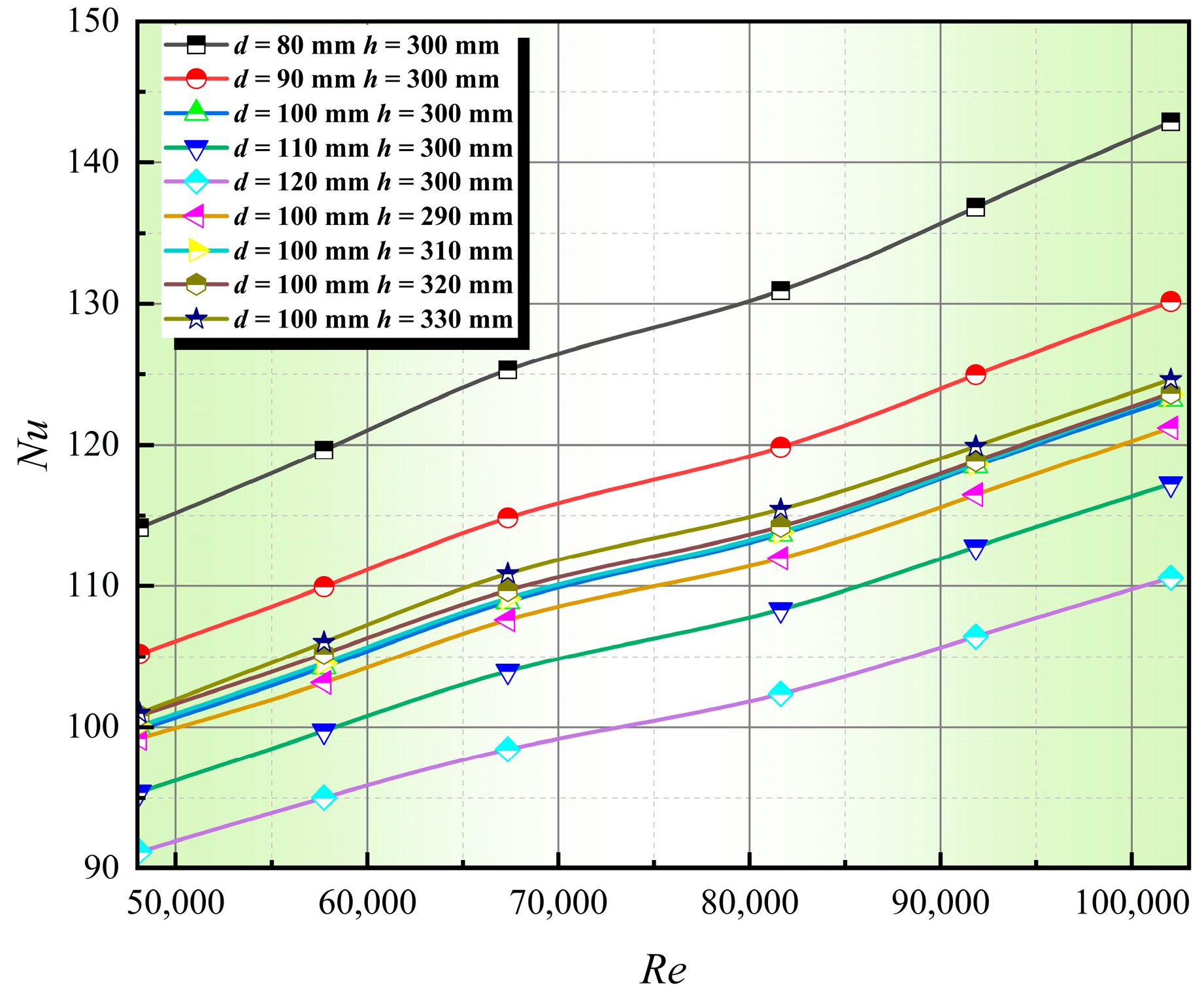
The air inlet-velocity within the shell significantly influences the performance of the heat exchanger. Increasing the velocity can raise Re, thereby strengthening convective heat transfer and improving Nu. However, excessively high inlet velocities can enlarge the negative pressure area before the shell outlet, leading to increased pressure and uneven heat transfer in localized areas. When exploring the optimal air-inlet velocity, one can start experimenting from low velocities and gradually increase the inlet flow rate, continuing until the heat transfer efficiency reaches a maximum and stabilizes, achieving the optimal inlet air velocity condition.
(3)
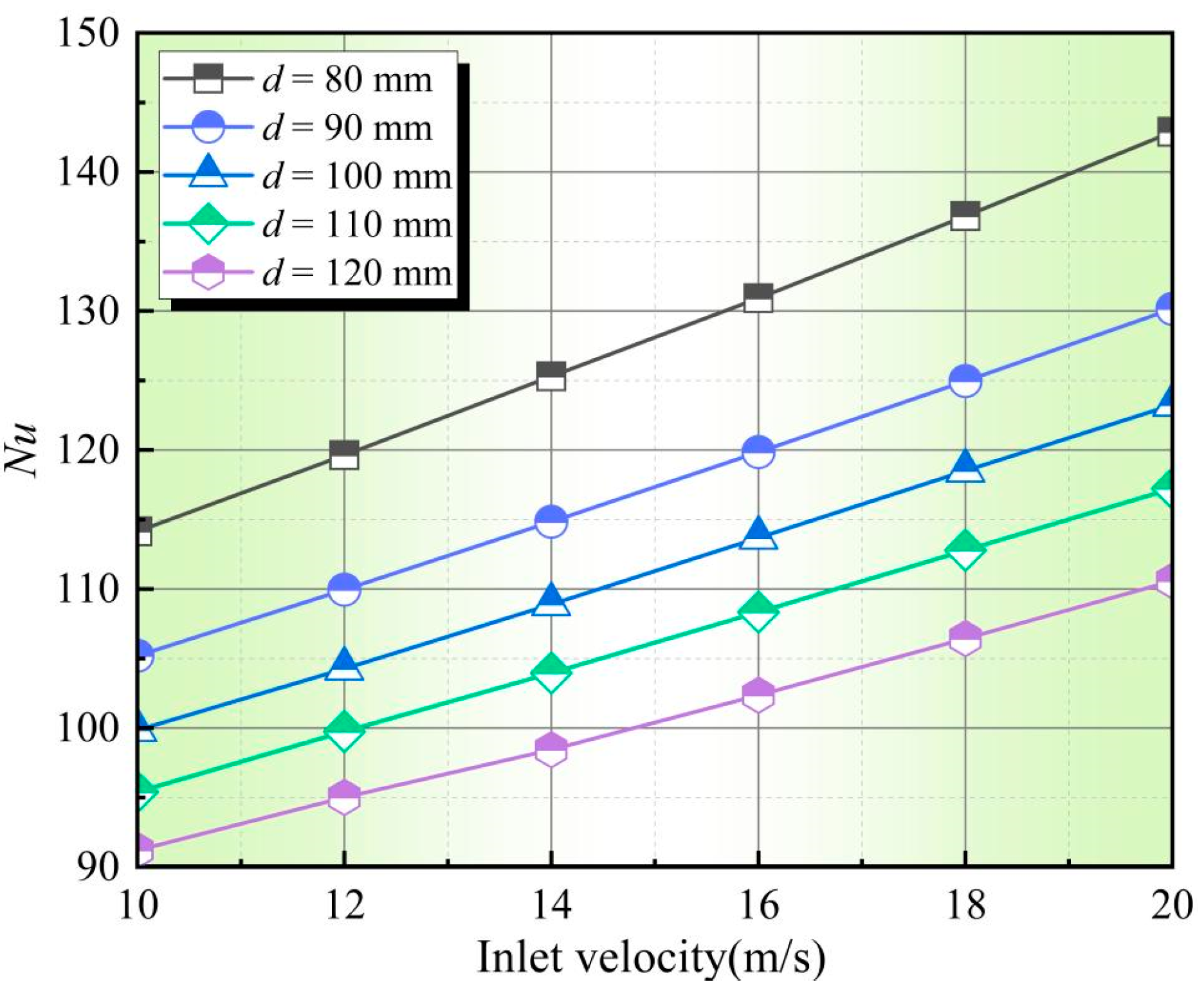
The diameter of the serpentine tubes shows an inverse relationship with Nu. Enlarging the tube diameter increases the heat exchange area but reduces the heat transfer rate per unit area. This reduction leads to a decrease in the convective heat transfer coefficient, subsequently decreasing Nu. Through comprehensive analysis, when d = 80 mm and h = 300 mm, the highest percentage increase in Nu concerning Re is 25.17%. At this point, the convective heat transfer strength is at its peak, resulting in optimal heat transfer performance.

Author Contributions

T.H.: Funding acquisition; Q.L. and W.L.: proofreading, supervision, simulation; F.Z.: analysis; L.S. and X.C.: experiment, data collation, writing—original manuscript. All authors have read and agreed to the published version of the manuscript.

Funding

Jiuquan Vocational and Technical College 2024 school-level key project number: [2024XJZXM04]; Gansu Province 2024 College Teachers Innovation Fund Project (2024B-343) and National Natural Science Foundation of China (52066011).

Data Availability Statement

The original contributions presented in the study are included in the article, and further inquiries can be directed to the corresponding author.

Acknowledgments

The authors would like to thank the anonymous reviewers and the editor for their valuable and insightful suggestions.

Conflicts of Interest

The authors declare no conflicts of interest.

References

  1. Han, F. The status quo and prospects of my country’s renewable energy development. Renew. Energy Resour. 2010, 28, 137–140. [Google Scholar]
  2. Peng, H.; Yao, K.; Cao, X.; Jiang, S.; Wang, Y.; Peng, F. Experimental study on the combustion characteristics of two different biomass briquettes. Acta Energiae Solaris Sin. 2016, 37, 1002–1008. [Google Scholar]
  3. Li, M.; Zhang, W.; Niu, Q.; Nie, C. Performance test of biomass stirling cogeneration system in rice drying. J. Eng. Thermophys. 2015, 36, 1847–1852. [Google Scholar]
  4. Fan, Z.; Ci, W.; Li, H.; Zhao, F.; Zhang, Z. Development of a new type of biomass hot blast stove. Agric. Equip. Veh. Eng. 2017, 55, 82–84. [Google Scholar]
  5. Li, W.; Li, Z.; Han, W.; Li, D.; Yan, S.; Zhou, J. Study of The Flow Characteristics of Pumped Media in The Confined Morphology of A Fer-rofluid Pump with Annular Microscale Constraints. J. Fluids Eng. 2025, 147, 021201. [Google Scholar] [CrossRef]
  6. Li, W.; Li, Z.; Han, W.; Tan, S.; Yan, S.; Wang, D.; Yang, S. Time-mean equation and multi-field coupling numerical method for low-Reynolds-number turbulent flow in ferrofluid. Phys. Fluids 2023, 35, 125145. [Google Scholar] [CrossRef]
  7. Tu, F.; Ma, S.; Gao, S.; Liu, Q.; Mao, J. Numerical simulation of the influence of incoming flow velocity distribution on the performance of radial heat pipe heat exchangers. J. Cent. South Univ. (Nat. Sci. Ed.) 2013, 44, 3904–3910. [Google Scholar]
  8. Liu, B.; Zhang, J.; Tan, X. The effect of jet impingement velocity on heat transfer under rotation effect. J. Eng. Thermophys. 2015, 36, 366–370. [Google Scholar]
  9. Hua, H.J.; Al-Obaidi, A.S.M.; Meng, C.W.; Hui, K.J.L.N. Effect of supply and exhaust air velocity on the enthalpy and temperature exchange efficiency of a paper heat exchanger. MATEC Web Conf. 2021, 335, 03006. [Google Scholar] [CrossRef]
  10. Li, S.; Lu, L.; Chen, J.; Chai, W.; Jiang, Y.; Zhang, H. Simulation study on the influence of structural parameters on the tube side heat transfer of the wound tube heat exchanger. Energy Conserv. Technol. 2017, 35, 498–504. [Google Scholar]
  11. Wang, S.; Jian, G.; Xiao, J.; Wang, J.; Wen, J. Numerical simulation study on multi-objective optimization of structural parameters of wound tube heat exchanger. J. Xi’an Jiaotong Univ. 2017, 51, 9–15. [Google Scholar]
  12. Lu, C.; Li, Z.; Wang, Q.; Liu, X. Numerical analysis of the effects of fin structure and PCM physical parameters on the thermal storage process of energy storage furnace. Therm. Power Eng. 2020, 35, 114–121. [Google Scholar]
  13. Zhao, X.; Li, J.; Xu, J.; Zhu, X.; Liao, Q. Numerical simulation of flow and heat transfer characteristics of three-dimensional rectangular externally finned tubes. J. Eng. Thermophys. 2019, 40, 907–915. [Google Scholar]
  14. Lazova, M.; Kaya, A.; Billiet, M.; Lecompte, S.; Manolakos, D.; De Paepe, M. Experimental Assessment of a Helical Coil Heat Exchanger Operating at Subcritical and Supercritical Conditions in a Small-Scale Solar Organic Rankine Cycle. Energies 2017, 10, 619. [Google Scholar] [CrossRef]
  15. Jiang, H.; Jiang, T.; Tian, H.; Wu, Q.; Deng, C.; Zhang, R. Heat Transfer Simulation and Structural Optimization of Spiral Fin-and-Tube Heat Exchanger. Electronics 2024, 13, 4639. [Google Scholar] [CrossRef]
  16. Patidar, N.; Makrariya, A.; Rasheed, R.H.; Singh, N.K.; Alsayah, A.M.; Alshukri, M.J.; Rathore, R.K. Model to identify comfortable cloth fabric for human body during thermal stress due to physical exercise. Mater. Res. Express 2024, 11, 085402. [Google Scholar] [CrossRef]
  17. Rathore, R.K.; Patel, P.; Singh, N.K.; Kaimkuriya, A.; Gajghat, R.H.; Kumbhalkar, M.A.; Verma, K. EES analysis of low-grade thermal energy organic-rankine-vapor compression-refrigeration system. AIP Conf. Proc. 2023, 2839, 020031. [Google Scholar]
  18. Yang, Y.; Ma, Q.; Zuo, Y. Heat transfer characteristics and parameter optimization of the flow channel of herringbone plate heat exchanger. Trans. Chin. Soc. Agric. Eng. 2019, 35, 210–215. [Google Scholar]
  19. Li, W.; Li, Z.; Han, W.; Li, Y.; Yan, S.; Zhao, Q.; Gu, Z. Pumping-velocity variation mechanisms of a ferrofluid micropump and structural optimization for reflow inhibition. Phys. Fluids 2023, 35, 052005. [Google Scholar]
  20. Li, W.; Li, Z.; Han, W.; Li, Y.; Yan, S.; Zhao, Q.; Chen, F. Measured viscosity characteristics of Fe3O4 ferrofluid in magnetic and thermal fields. Phys. Fluids 2023, 35, 012002. [Google Scholar] [CrossRef]
  21. Chen, F.; Zhang, J.; Li, Z.; Yan, S.; Li, W.; Yan, Z.; Liu, X. Effect of the surface coating of carbonyl iron particles on the dispersion stability of magnetorheological fluid. Sci. Rep. 2024, 14, 11358. [Google Scholar] [CrossRef] [PubMed]
  22. Li, W.; Li, Z.; Qin, Z.; Yan, S.; Wang, Z.; Peng, S. Influence of the solution pH on the design of a hydro-mechanical magneto-hydraulic sealing device. Eng. Fail. Anal. 2022, 135, 106091. [Google Scholar] [CrossRef]
  23. Xu, L.; Kan, K.; Zheng, Y.; Liu, D.; Binama, M.; Xu, Z.; Yan, X.; Guo, M.; Chen, H. Rotating stall mechanism of pump-turbine in hump region: An insight into vortex evolution. Energy 2024, 292, 130579. [Google Scholar] [CrossRef]
  24. Li, W.; Li, Z.; Han, W.; Wang, Y.; Zhao, J.; Zhou, J. Morphologic transformation of ferrofluid during micropump driving under field control. Ann New York Acad Sci. 2025, 1543, 194–203. [Google Scholar] [CrossRef] [PubMed]
  25. Liu, D.; Li, Z.; Xu, L.; Li, J.; Yang, Y.; Wang, X.; Pang, J.; Liu, X. Vortex motion in vaneless space and runner passage of pump-turbine in S-shaped region. Phys. Fluids 2024, 36, 0194239. [Google Scholar] [CrossRef]
  26. Ren, Z.; Li, D.; Wang, H.; Liu, J.; Li, Y. Computational model for predicting the dynamic dissolution and evolution behaviors of gases in liquids. Phys. Fluids 2022, 34, 103310. [Google Scholar] [CrossRef]
  27. Wang, X.; Zheng, N.; Liu, P.; Liu, Z.; Liu, W. Analysis of flow and heat transfer performance of wave-baffled rod heat exchanger. J. Eng. Thermo-Phys. 2016, 37, 1758–1762. [Google Scholar]
  28. Liu, J.; Liu, W. Numerical simulation of heat transfer and flow in a rod baffle heat exchanger using deep groove spiral bellows. J. Eng. Thermophys. 2015, 36, 151–153. [Google Scholar]
  29. Yang, S.; Tao, W. Heat Transfer, 5th ed.; Higher Education Press: Beijing, China, 2019; pp. 344–350. [Google Scholar]
  30. Ren, Z.; Li, D.; Zhou, W.; Li, Z.; Wang, H.; Liu, J.; Li, Y.; Khoo, B.C. Gas–liquid mass-transfer characteristics during dissolution and evolution in quasi-static and dynamic processes. Int. J. Multiph. Flow 2024, 180, 104970. [Google Scholar]
  31. Qin, X.; Wang, S.; Yuan, Y. Heat Transfer Coefficient Estimation and Performance Evaluation of Shell and Tube Heat Exchanger Using Flue Gas. Processes 2021, 9, 939. [Google Scholar] [CrossRef]
  32. Bahadori, A. Prediction of compressed air transport properties at elevated pressures and high temperatures using simple method. Appl. Energy 2010, 88, 1434–1440. [Google Scholar] [CrossRef]
  33. Zhou, W.; Jin, X.; Ding, L.; Ma, J.; Su, H.; Zhao, A. Research on vibration signal decomposition of cracked rotor-bearing system with double-disk based on CEEMDAN-CWT. Appl. Acoust. 2024, 227, 110254. [Google Scholar] [CrossRef]
  34. Jin, X.; Zhou, W.; Ma, J.; Su, H.; Liu, S.; Gao, B. Analysis on the vibration signals of a novel double-disc crack rotor-bearing system with single defect in inner race. J. Sound Vib. 2025, 595, 118729. [Google Scholar] [CrossRef]
  35. Zhou, W.; Qiu, N.; Wang, L.; Gao, B.; Liu, D. Dynamic analysis of a planar multi-stage centrifugal pump rotor system based on a novel coupled model. J. Sound Vib. 2018, 434, 237–260. [Google Scholar] [CrossRef]
Figure 1. Experimental model and test system.
Processes 13 00588 g001
Figure 2. Computational physical model of heat exchanger.
Processes 13 00588 g002
Figure 3. Grid model and grid independence.
Processes 13 00588 g003
Figure 4. Comparison of the experimental and numerical results for the air convective heat transfer coefficient, pressure, temperature, and flue gas outlet velocity at different air-inlet flow rates: (a) Variation in air convective heat transfer coefficient at different inlet flow rates. (b) Changes in air pressure at different inlet flow rates. (c) Variation in air temperature at different inlet flow rates. (d) Variation in air outlet velocity at different inlet flow rates.
Processes 13 00588 g004
Figure 5. Temperature cloud of the heat exchanger axial section for different air-inlet velocities: (a) Re = 48,108; (b) Re = 72,162; (c) Re = 102,043.
Processes 13 00588 g005
Figure 6. Velocity cloud of the heat exchanger axial section for different air-inlet velocities: (a) Re = 48,108; (b) Re = 72,162; (c) Re = 102,043.
Processes 13 00588 g006
Figure 7. Pressure cloud of the heat exchanger axial section for different air-inlet velocities: (a) Re = 48,108; (b) Re = 72,162; (c) Re = 102,043.
Processes 13 00588 g007
Figure 8. The relationship between flow velocity and Nu under different pipe diameters.
Processes 13 00588 g008
Figure 9. The relationship between flow velocity and Nu under different bump spacing.
Processes 13 00588 g009
Figure 10. Relationship between Re and Nu under different working conditions.
Processes 13 00588 g010
Table 1. Material property parameters.
MaterialCuSteel
ρ (kg/m3)89307750
W (m·K)37031.1
Table 2. Physical parameters of flue gas [31].
T/°C ρ k g / m 3 c p k J / ( k g K ) λ   ×   10 2 W / ( m K ) μ   ×   10 6 P a s
5000.4571.1856.5603.408
6000.4071.2417.4203.790
7000.3631.2398.2474.007
8000.3031.2379.4424.307
9000.2521.23510.6214.609
10000.2041.23311.8544.907
11000.1531.23112.0785.206
Table 3. Air property parameters [32].
T/°C ρ k g / m 3 c p k J / ( k g K ) λ   ×   10 2 W / ( m K ) μ   ×   10 6 P a s
101.2471.0052.5117.6
201.2051.0052.5918.1
301.1651.0052.6718.6
401.1281.0052.7619.1
501.0931.0052.8319.6
601.0601.0052.9020.1
701.0291.0092.9620.6
801.0001.0093.0521.1
900.9721.0093.1321.5
1000.9461.0093.2121.9
1200.8981.0093.3422.8
Table 4. Error analysis of numerical calculation and experimental test.
ParameterTVPhc
Numerical simulation306.6712.93449135.03
Experimental test317.42113.5814721.13636.113
Relative error %3.394.794.873.00
Disclaimer/Publisher’s Note: The statements, opinions and data contained in all publications are solely those of the individual author(s) and contributor(s) and not of MDPI and/or the editor(s). MDPI and/or the editor(s) disclaim responsibility for any injury to people or property resulting from any ideas, methods, instructions or products referred to in the content.

