Article

Experimental Study of Injection–Production Coupling Technique for Enhanced Oil Recovery in Mature Water Flooding Reservoirs

1
Exploration and Development Research Institute, Sinopec Jianghan Oilfield Company, Wuhan 430223, China
2
College of Petroleum Engineering, Yangtze University, Wuhan 430100, China
3
Key Laboratory of Drilling and Production Engineering for Oil and Gas, Wuhan 430100, China
*
Author to whom correspondence should be addressed.
Processes 2025, 13(2), 457; https://doi.org/10.3390/pr13020457
Submission received: 14 November 2024 / Revised: 19 December 2024 / Accepted: 15 January 2025 / Published: 8 February 2025
(This article belongs to the Section Energy Systems)

Abstract

:
Water flooding is one of the most widely used secondary oil recovery methods for enhanced oil recovery (EOR). However, as a reservoir matures, excessive water production often accompanies oil production. To address this issue, the injection–production coupling technique (IPCT) has been proposed to control water production and improve oil recovery. Despite its practical application, the underlying mechanisms governing the injection–production process remain unclear. To investigate this, a transparent heterogeneous sand pack model and a visualization micro-model were employed to examine the impact of the injection–production mode on oil recovery and to uncover the mechanisms of enhanced oil recovery. The results indicate that, compared to the conventional continuous injection–production mode, both the fluid flow swept area and incremental oil recovery are significantly higher in the IPCT. Sweep efficiency improves by adjusting the injection–production streamlines and displacement directions. Notably, the oil displacement effect in the “stop injection” mode is more effective than in the “reduce injection” mode. These findings suggest that the coupling injection–production mode can efficiently recover residual oil in low permeability zones, thereby enhancing overall oil recovery.

1. Introduction

Water flooding is recognized as one of the most common secondary oil recovery techniques because it is economically advantageous for oil reservoir development. As the oilfields become mature and enter the high water cut development stage, due to the long-term water flooding, the injected water enters through the preferential flow channel and leads to large amounts of remaining oil un-recovered, resulting in the increase of water production and decrease of oil production. Thus, it is essential to recover the remaining oil and enhance oil recovery. Different techniques have been applied to reduce water production and increase oil production, such as water shutoff and profile control technology, chemical flooding, cyclic water injection, and so on. The water shutoff and profile control technology can plug the high permeability thief zone by injecting the plugging agents into the formation and diverting the subsequent injection fluid into the low permeability zone to recover the remaining oil. Chemical flooding technology such as polymer flooding [1,2,3,4,5], surfactant-polymer flooding [6,7,8,9,10,11,12], and heterogeneous phase combined flooding [13,14,15,16,17,18,19,20] have been applied to enhance oil recovery by improving sweep efficiency and oil displacement efficiency. However, considering the economic effect, the improved water flooding technology, including well pattern adjustment [21], infilling well [22,23,24], and cyclic water injection and injection–production optimization [25,26], has been successfully applied in mature water flooding reservoir to improve oil recovery.
As the oilfield enters into the high water cut stage, under the conventional injection-production mode, the injection water always flows along the fixed-formed high permeability thief zone and cannot recover the remaining oil in the non-main streamline zone. Thus, on the basis of improved water flooding technology, to expand the sweep efficiency and recover the remaining oil in the non-main streamline zone, the injection–production coupling technique (IPCT) was first proposed and applied in the fault block reservoir of the Shengli oilfield. Injection–production coupling technology is a technology with coordinated injection and production implemented between wells, which is a general term for periodic water injection, intermittent water injection, and unstable water injection technology. It mainly uses the method of periodically increasing and reducing water injection to make the high and low permeable layers within the oil layer generate unstable pressure differences, allowing fluid from the low permeable zone with high oil saturation to flow to the high permeable zone. The production of low-permeability oil has been significantly improved. In 2004, Stripe et al. used numerical simulation methods to study the impact of unstable water injection cycles on production results in Lagocinco Oilfield [27]. Through physical simulation experiments, Wang found that injection–production coupling technology can effectively improve the development effect of stratified heterogeneous sandstone reservoirs [28]. Unstable water injection experiments conducted by Wang indicated that suction back occurred in low-permeability layers during the injection reduction stage [29]. Xu et al. studied the effects of injection time, injection method, injection cycle, and injection/production ratio on production [30]. The research by Xie et al. has shown that for ultra-low permeability reservoirs with severe heterogeneity, periodic water injection can be adopted to achieve better oil increase and precipitation effect [31]. The injection–production coupling technique was achieved by adopting the alternative injection–production mode of injection and production well. That is to say, under the fixed injection–production pattern, when the injection well starts injecting water in a certain layer, the corresponding production well shuts off, and the other layers will produce. After a period of time, the injection well stops injection, and the corresponding production well will start production. Up to now, the injection–production coupling technique has been applied in complex fault block mature water flooding reservoirs and has achieved the effect of decreasing water production and increasing oil production [32,33,34,35]. Although the injection–production coupling technology has achieved successful application, the effect of the injection–production mode on the flooding efficiency is not clear, and the enhanced oil recovery mechanism on a micro-scale has not been clarified. To better apply the injection–production coupling technology, thus, in this study, to optimize the injection–production mode and clarify the enhanced oil recovery (EOR) mechanism governing the injection–production coupling technique, the heterogeneous transparent sand pack model and micro-etching model were used to conduct flooding experiments from different scale levels. First, the heterogeneous transparent plate sand pack mode was used to investigate the flooding efficiency under different injection–production modes to analyze the fluid sweep efficiency, remaining oil distribution, and fluid flow direction. Then, the injection–production mode was optimized by the incremental oil recovery. Finally, the micro-etching model flooding experiments were conducted to investigate the water flooding recovery difference between the conventional injection–production mode and alternating injection–production mode to reveal the mechanism governing enhanced oil recovery. This study can provide a basis for the application of injection–production coupling technique (IPCT) in mature water flooding reservoirs.

2. Experimental Method

2.1. Materials

The sodium chloride (NaCl), calcium chloride (CaCl2), and magnemodel were composed of two glass plates, including the etched plate and cover plate. Magnesium chloride (MgCl2) and sodium bicarbonate (NaHCO3), purchased from Aladdin Reagents Co., Ltd., Shanghai, China, were used to prepare the simulated formation brine. The deionized water was obtained from our own laboratory. The two-dimensional heterogeneous transparent sand pack model was designed, as shown in Figure 1. The heterogeneous transparent sand pack model was fabricated by using different mesh quartz sand and epoxy resin to stick onto the glass. The size of the sand pack model is 30 cm × 30 cm × 2 mm. The model has six drilled ports, including three inlets and three outlets, which can be used to simulate the well pattern. The porosity of the sand pack model is 36.5%. The heterogeneous transparent sand pack model has a high permeability and low permeability zone. The permeability of the high permeability zone and the low permeability zone of the sand pack model is about 3.0 μm2 and 1.0 μm2, respectively.
The micro-etching model was fabricated using the laser etching method. The micro-etching is attached together and sealed to form an enclosed pore space. The etched plate was designed as a heterogeneous pore size distribution. The pore size of the high permeability zone and low permeability zone is 50~100 μm and 10~50 μm, respectively. The size of the micromodel is 4 mm × 4 mm. The micromodel has six drilled ports, including three inlets and three outlets, which can be used to simulate the well pattern. The micro-model pattern is shown in Figure 2. All the experiments were conducted at 25 °C. The brine water and simulated crude oil were colored Naphthol Green and Sudan Red, respectively.

2.2. Methods

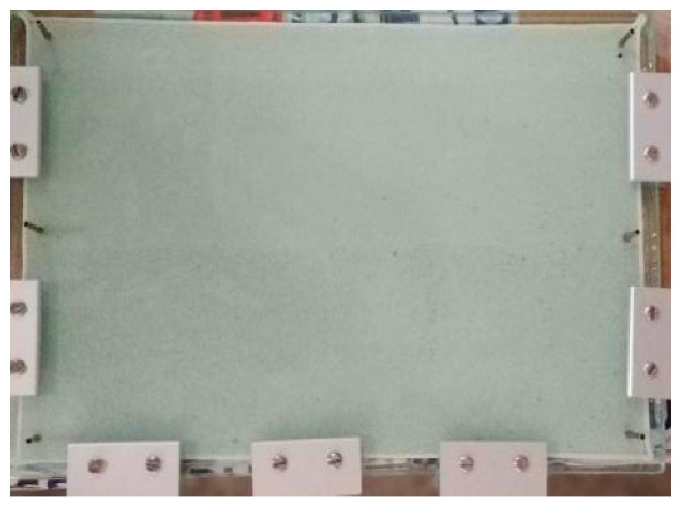
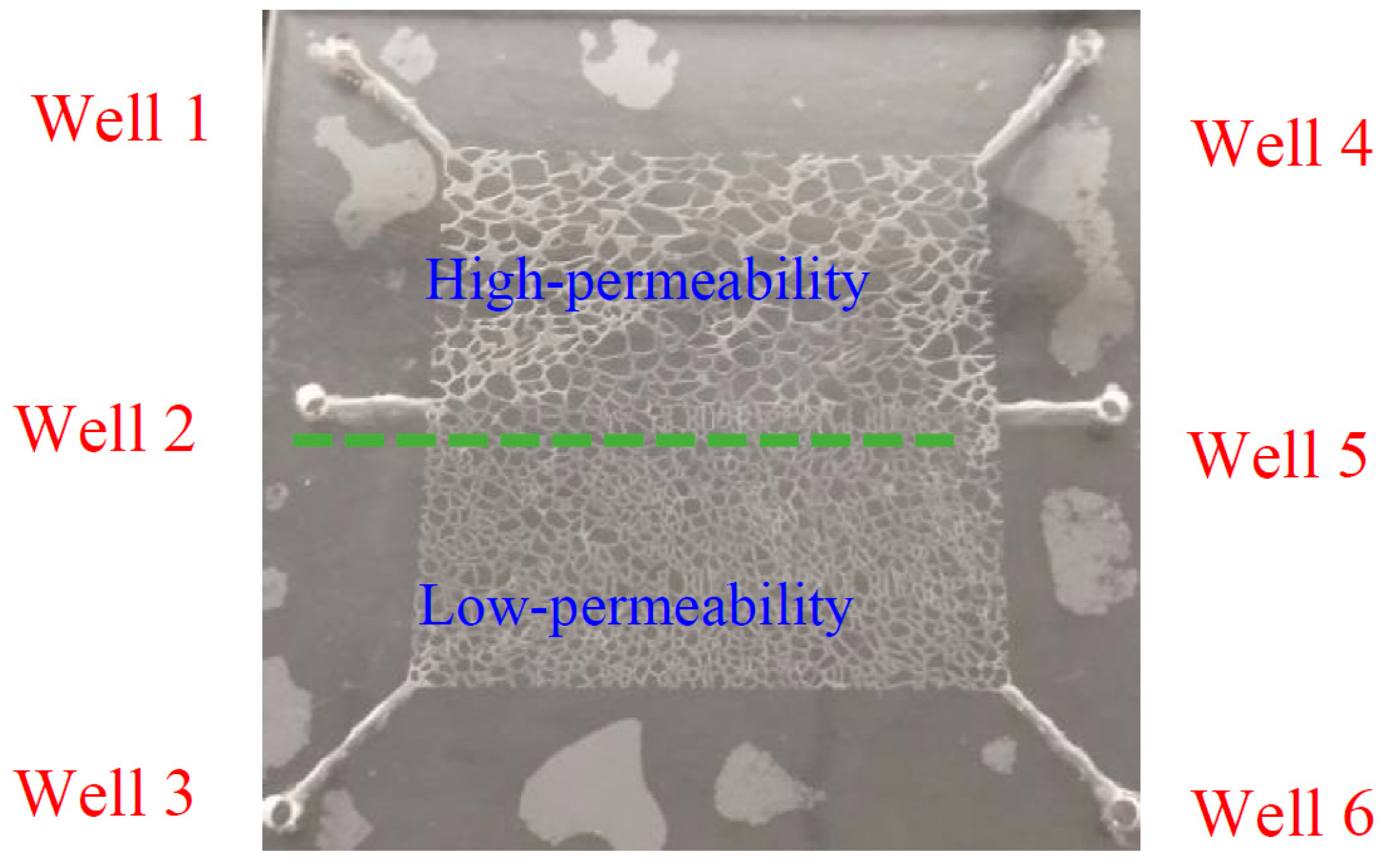
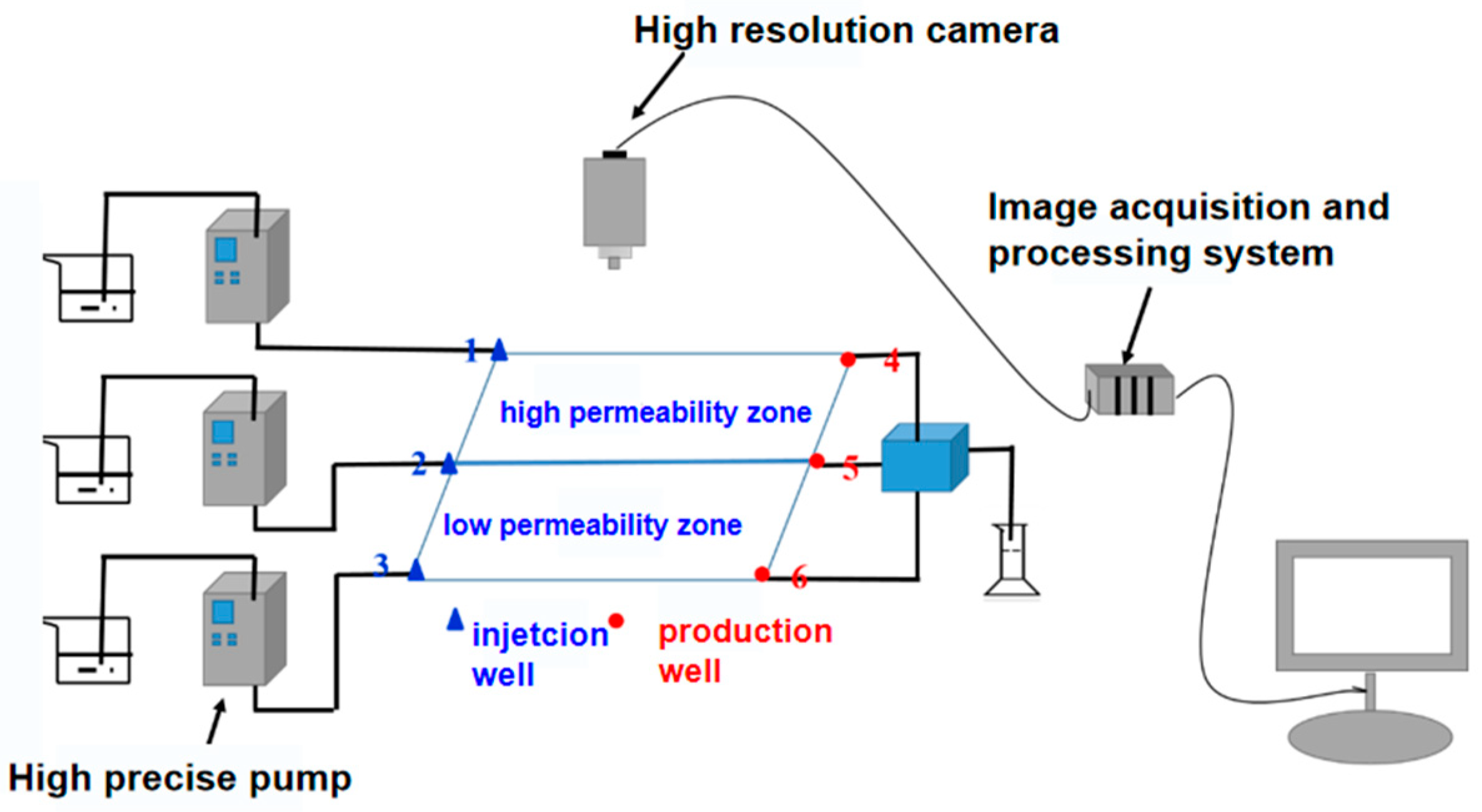
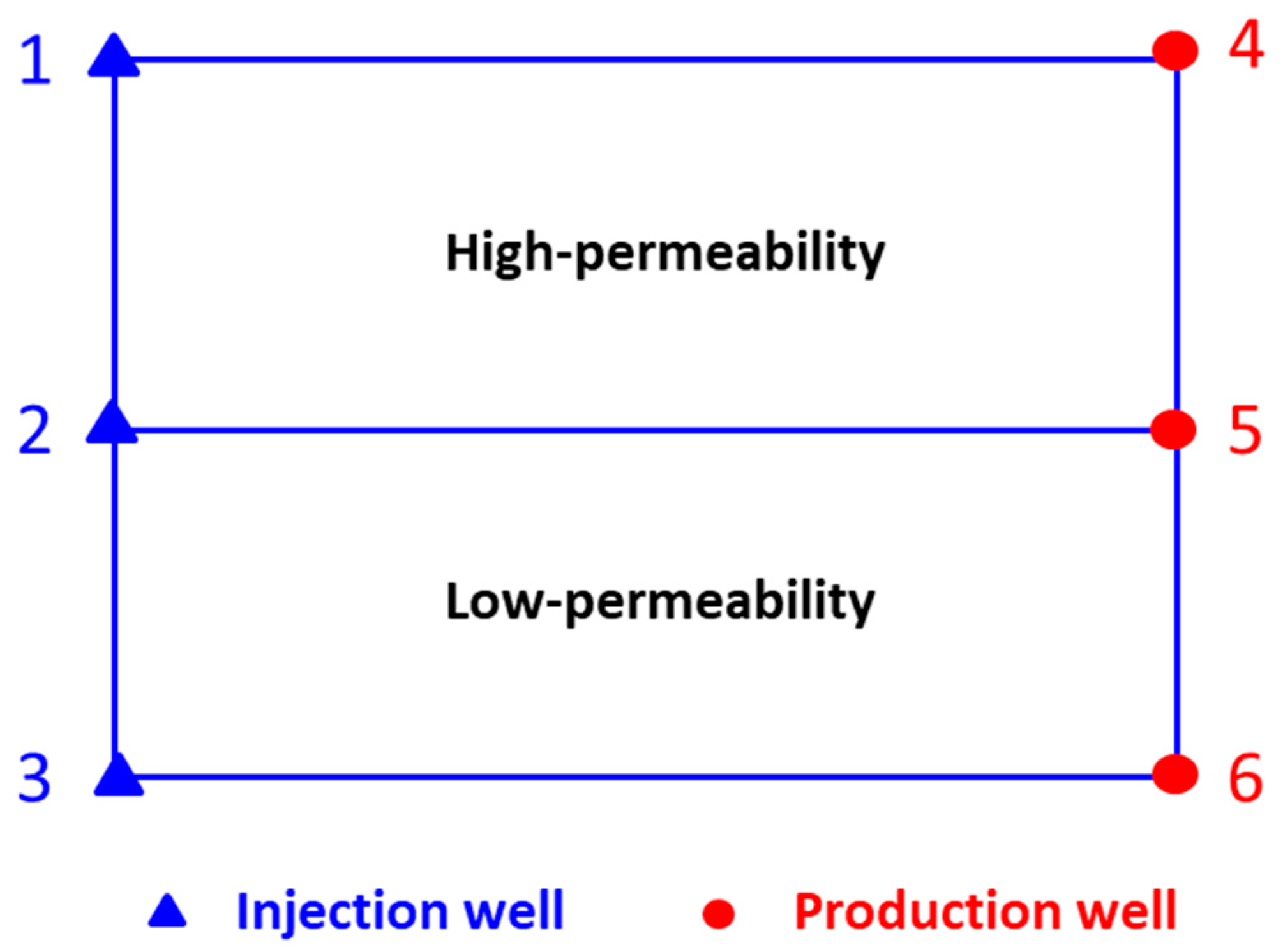
2.2.1. The Transparent Heterogeneous Sand Pack Flooding Test

The transparent sand pack experimental apparatus was used to investigate the effect of the injection–production mode on the enhanced oil recovery. The experimental apparatus was composed of a transparent plate sand pack model, a high-precision pump, an LED light source, a high-resolution camera, and an image acquisition and processing system. A camera with a high resolution was used to record the fluid’s flow through the plate and pack model at different stages of the displacement processes. The image acquisition and processing system can be used to measure the oil saturation changes within the model.
The experimental procedure of the transparent heterogeneous sand pack flooding test was as follows: (1) Oil saturated period: The sand pack model was vacuumed and saturated with formation brine. Then, the simulated crude oil was injected into the transparent plate sand pack until no water was produced at different injection rates from 0.1 mL/min to 1.0 mL/min. (2) Initial water flooding period: Then water flooding was conducted at the injection rate of 0.5 mL/min until the water cut reached 90%. (3) Final water flooding period. Then, the subsequent water was injected into the sand pack model until no more oil could be produced at the injection rate of 0.5 mL/min under different injection modes, as shown in Figure 3. For example, the conventional injection–production mode is when injection wells 1#, 2#, and 3# inject water slug simultaneously, and production wells 4#, 5#, and 6# produce simultaneously. However, for the injection–production coupling mode, during the coupling upper half cycle, when injection wells 1# and 3# inject water slug, the production well 5# produces. During the coupling lower half cycle, when injection well 2# injects water slug, the production wells 4# and 6# produce.

2.2.2. The Micro-Model Flooding Test

Based on the results of the heterogeneous sand pack flooding test, the glass-etched micro-model experiments were conducted to investigate the enhanced oil recovery mechanism under injection–production coupling mode. The glass-etched micromodel flooding experimental procedure was as follows: (1) The micromodel was completely saturated with crude oil. (2) Initial water flooding period. The water flooding was conducted until the water cut was 90% at the injection rate of 0.01 mL/min. (3) Final water flooding period. The water flooding was conducted again at the injection rate of 0.01 mL/min until no more oil was produced from the model under conventional water injection and injection–production coupling mode. (4) The flooding processes at different flooding stages were recorded, and the remaining oil distribution was analyzed to calculate the incremental oil recovery.

3. Results and Discussion

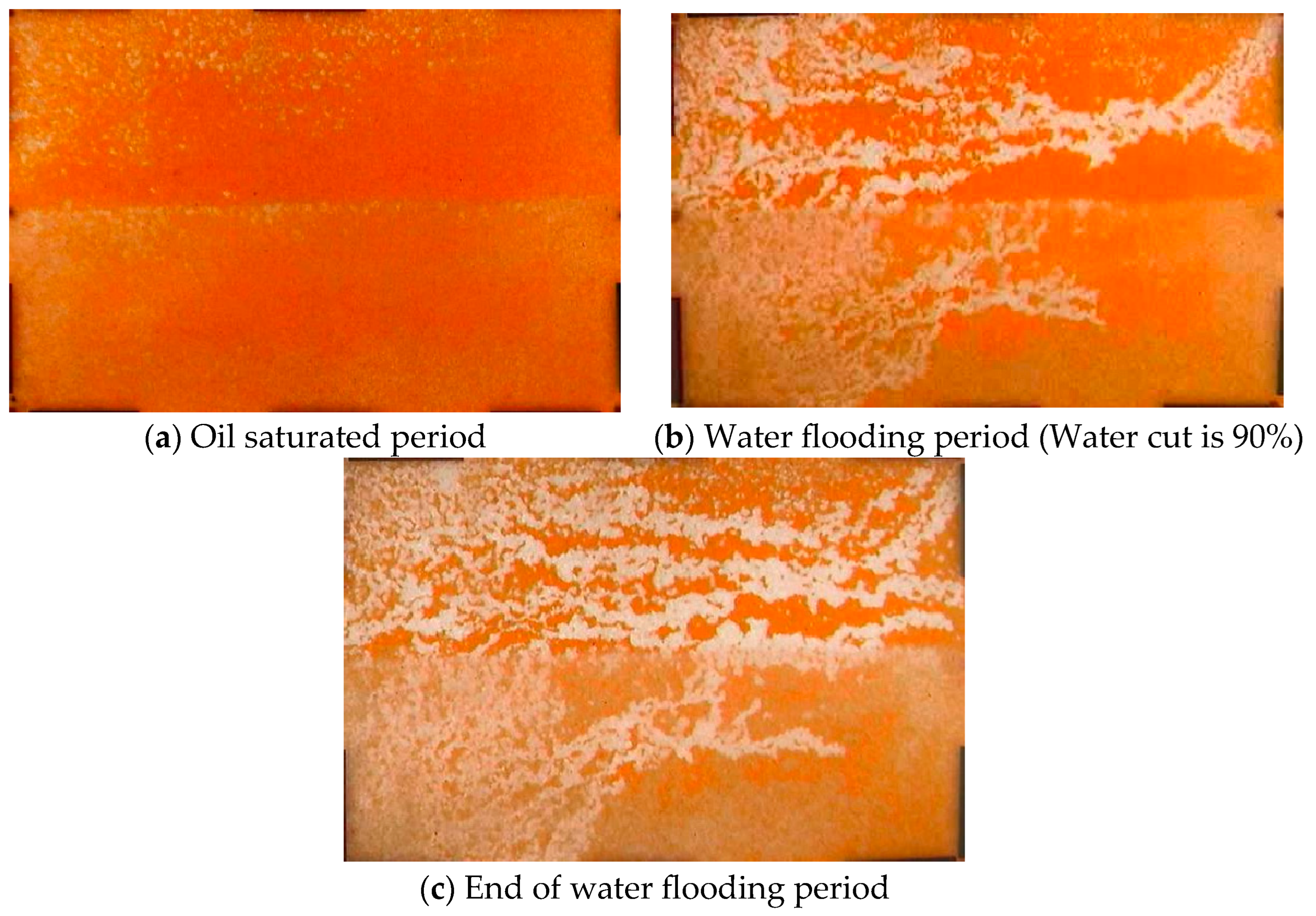
3.1. Oil–Water Distribution Characteristic Under Conventional Injection–Production Mode

3.1.1. The Remaining Oil Distribution Characteristic

The basic conventional water flooding experiment is designed as three injection wells (wells 1#, 2#, and 3#) and three production wells (wells 4, 5, and 6), as shown in Figure 4. The experiment is stopped when the water flooding reaches a water content of about 98%.
According to the transparent heterogeneous sand pack flooding experimental procedure, the remaining oil distribution characteristics at different flooding stages were recorded by using a video automatic acquisition device, shown in Figure 5. Under conventional water injection–production mode, water flooding was conducted until the water cut reached 98%. The streamlining and remaining oil distribution at different stages during the flooding process can be qualitatively analyzed.
During the conventional continuous water flooding period, due to the difference in permeability between high and low-permeability areas, the injected water is prone to advance along the high permeability zone. With the extension of injection time, a clear water flooding advantage seepage channel is easily formed. Moreover, due to the low resistance of the advantage seepage channel, after the formation of the advantage seepage channel, the injected water will advance along the advantage seepage channel with the lowest flow resistance, resulting in a higher degree of utilization in the high permeability zone than in the low-permeability zone.

3.1.2. The Incremental Oil Recovery Analysis

The image process software was used to characterize the oil saturation at different stages, and then the oil recovery was calculated according to the different oil saturation. Figure 6 depicts the incremental oil recovery results at different stages of conventional and coupling injection–production mode. The incremental oil recovery is defined as the difference between the initial oil recovery when the water cut is 90% and the final oil recovery when the water cut is 98%. Under conventional injection–production mode, during the initial water flooding period, the oil recovery is 38.75%. At the end of the water flooding period, the oil recovery is 50.12. Thus, under the conventional injection–production mode, the incremental oil recovery is 11.37%.

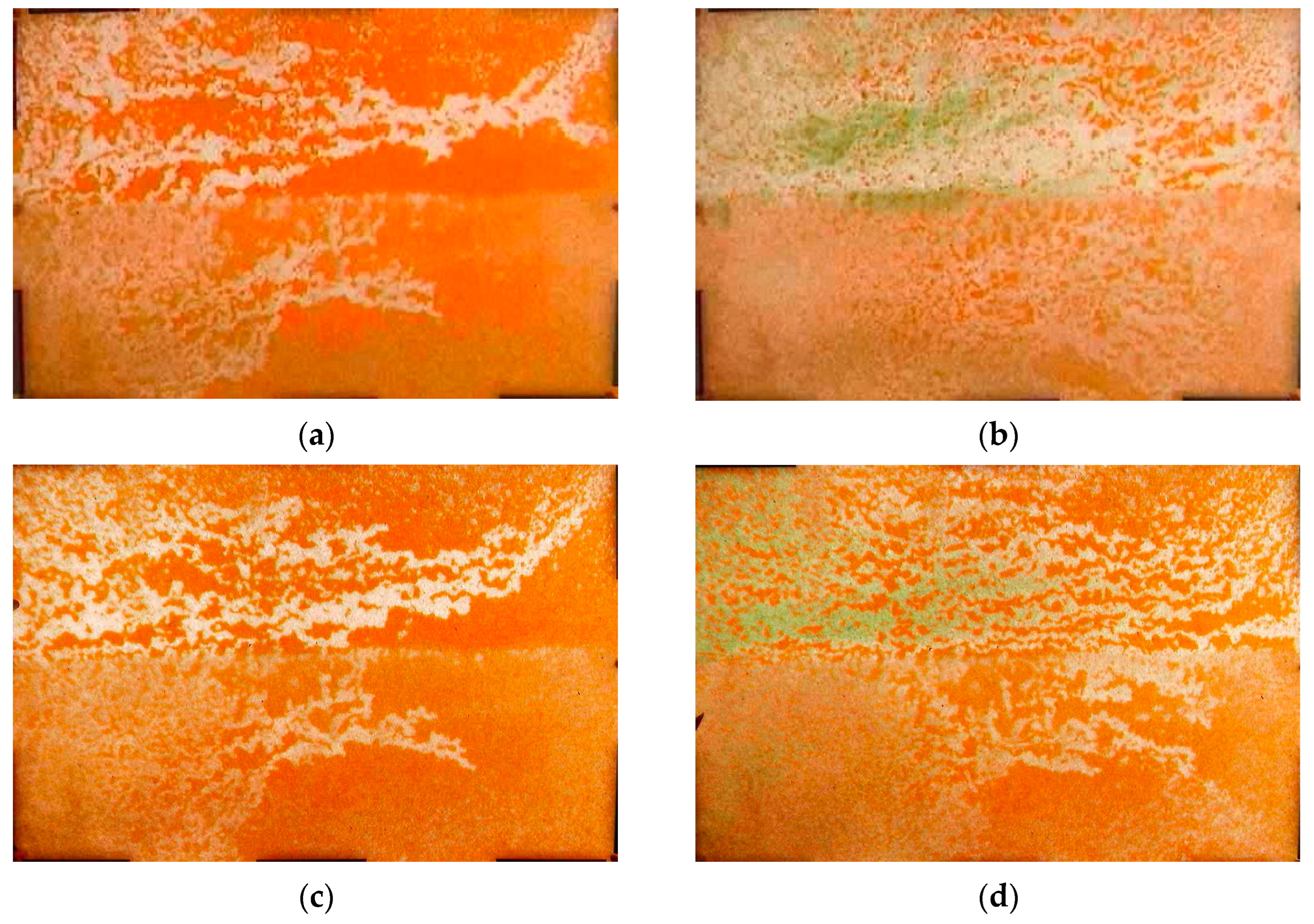
3.2. Oil–Water Distribution Characteristics Under Coupled Injection–Production Mode

On the basis of the conventional continuous injection–production mode, to investigate the mechanism governing the IPCT, the heterogeneous transparent sand pack model was used to investigate the flooding efficiency under different injection–production modes to analyze the fluid sweep efficiency and remaining oil distribution and fluid flow direction. The influence of different coupled injection–production well layout modes, injection well “stop injection” and “reduce injection” modes of the coupled injection–production structure on the oil flooding effect under the injection–production coupling mode. Compared with the conventional continuous injection–production mode, the fluid flow swept area, oil–water distribution characteristics, and incremental oil recovery were analyzed.

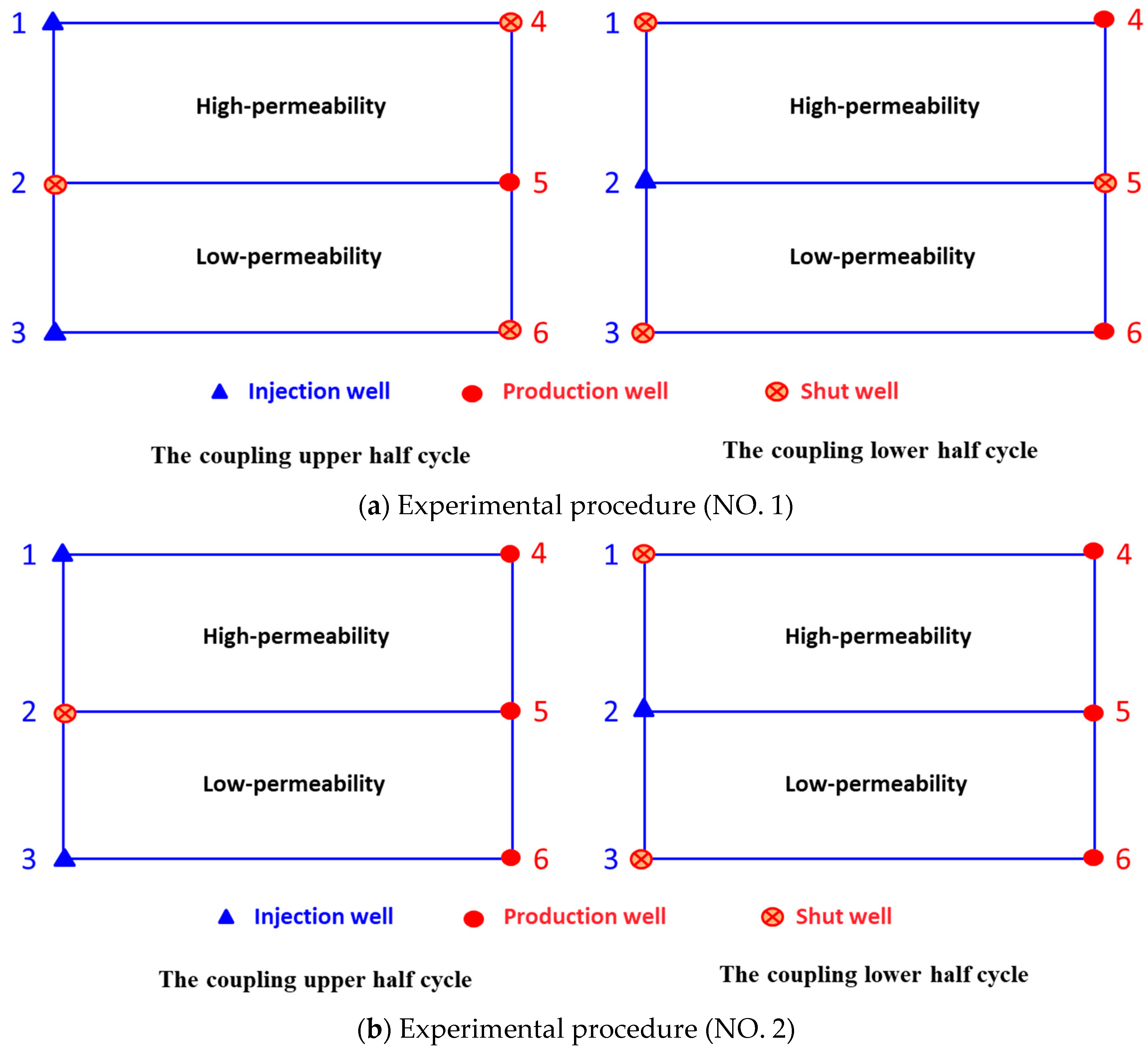
3.2.1. Effect of Coupled Injection–Production Well Pattern

When water flooding is conducted until the water cut reaches 90% under continuous injection–production mode, then coupling water injection is carried out until no oil is produced according to different coupling injection–production well layout modes. The naphthol green B was used to darken the subsequent water injection color for easy observation under the coupled injection–production mode. The coupled injection–production well pattern was designed as shown in Table 1. Figure 7 shows the oil–water distribution and remaining oil distribution at different flooding stages under different injection–production well patterns.
During the water flooding period, due to the permeability difference between the high permeability zone and low permeability zone, the injected water will easily flow through the high permeability zone. As the injection time lengthened, the obvious dominant flow channel was formed in the high permeability zone. After the dominant flow channel was formed, due to the low flow resistance of the dominant flow channel, the breakthrough of injected water occurred, resulting in more oil being recovered in the high permeability zone than in the low permeability zone, as shown in Figure 8a. Then, according to the coupled injection–production well pattern, the remaining oil distribution under different injection–production modes is different. Compared with the image of remaining oil distribution in Figure 8b,c, during the coupling upper half cycle, when injection wells 1# and 3# inject water slug, and production well 5# produces, the sweep efficiency is higher, and the remaining oil is obviously less. According to the image processing software Image J (Version 1.53 K), the oil recovery results at different stages of different injection–production well patterns under coupling injection–production mode are summarized in Table 2.
As can be seen from Table 2, compared with the conventional injection–production mode, the initial oil recovery during the initial water flooding period is almost the same. However, under the coupled injection–production mode, the oil recovery at the end of the water flooding period is higher. Moreover, during the coupling upper half cycle, when injection wells 1# and 3# inject water slug and the production well 5# produces, the incremental oil recovery is higher.

3.2.2. Effect of Coupled Injection–Production Mode

In the actual production process, the injection well cannot be completely shut off, resulting in the reduction of the injection amount. It is necessary to investigate the effect of coupled injection–production modes, including “reduced injection” and “stop injection” modes, on the swept efficiency and oil recovery. The injection wells that need to be closed during the coupling of the upper and lower half cycles should be “reduced” to 1/4 and 1/2, respectively, and compared with the oil displacement effect under the “stop injection” mode. Table 3 and Figure 9 show the design of the coupled injection–production mode. Figure 10 shows the oil–water distribution and remaining oil distribution at different flooding stages under different injection–production modes.
According to Figure 10, it can be observed that due to the difference between high and low permeability, the oil recovery in the high permeability zone is higher than that in the low permeability zone. Additionally, due to the fact that the injection well is not completely closed in the “reduced injection” mode, there are differences in the degree of water-swept area. When the “reduced injection” reaches half of the injection volume, the water-swept area in the low permeability zone is the smallest.
Comparing the remaining oil distribution in the high permeability zone at the end of the water flooding period, it can be found that the remaining oil volume in the “stop injection” mode is much lower than that in the “reduce injection” mode, indicating that the oil displacement effect in the “stop injection” mode is better than that in the “reduce injection” mode. According to the image processing software Image J, the oil recovery results at different stages of different injection–production modes are summarized in Table 4. Under different coupled injection–production modes, the incremental oil recovery under stop injection mode is higher than that under reduced injection mode.

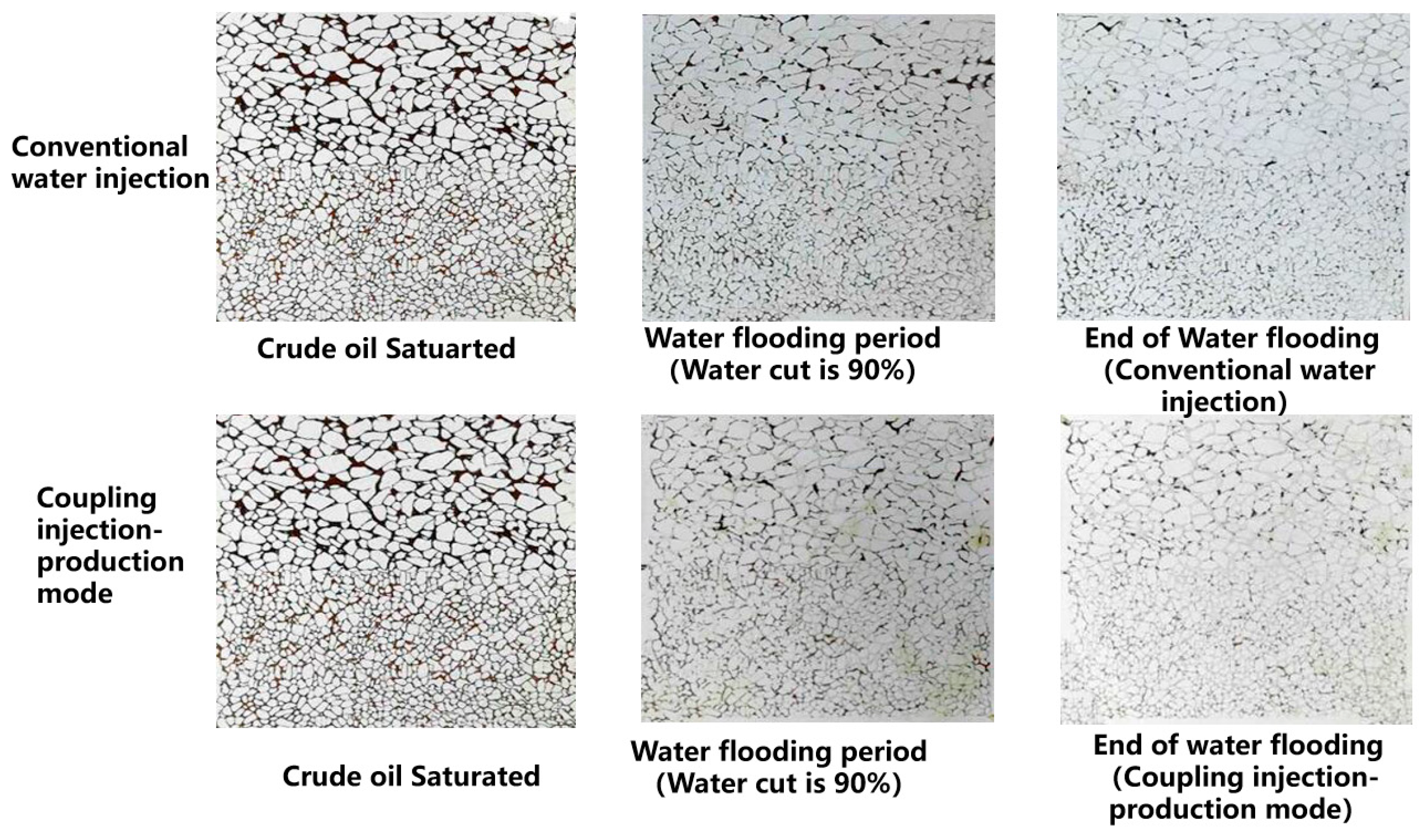
3.3. Micro-Model Flooding Results

The heterogeneous micro network etching model was used to investigate the enhanced oil recovery mechanism of coupling injection–production mode from the pore-scale level. The oil–water distribution and remaining oil distribution at each displacement stage were recorded. Then, the image processing software Image J was used to preliminary process the images of initial water flooding and end of water flooding. The remaining oil distribution and oil recovery results are shown in Figure 11.
As shown in Figure 8, when the water cut is 90%, the remaining oil distribution after water flooding is similar under conventional and coupling injection–production mode. Compared with the initial water flooding period, it can be found that the remaining oil in the high permeability zone is less, while there is still a large amount of remaining oil in the low permeability zone, which echoes the experimental phenomenon of the plate model. At the end of the water flooding period under conventional injection mode and coupling injection methods, the remaining oil distribution in the high permeability layer and the low permeability layer are compared. It can be seen that the distribution of remaining oil in the high-permeability layer is similar, and the difference in the low-permeability layer is obvious. The remaining oil in the low-permeability layer under conventional injection mode is significantly higher than that in the low-permeability layer under coupled injection mode, indicating that the coupled injection can be significantly improved.
Based on the above analysis, Image J image processing software was used to further process the oil displacement pictures at different stages under different injection modes. The oil saturation of each oil displacement stage was analyzed, the oil recovery degree of each stage was calculated, and the data were obtained, which is plotted in Figure 12.
Compared with the conventional injection–production mode, the incremental oil recovery under coupled injection–production mode is higher, which echoes the experimental results of the plate model flooding. Additionally, as can be seen from Figure 11, compared with the conventional injection–production mode, the swept area is higher, and more remaining oil in the low-permeability zone can be recovered.

4. Conclusions

In this study, the transparent heterogeneous sand pack model and visualization micro-model were used to investigate the effect of injection–production mode on the oil recovery and reveal the enhanced oil recovery mechanism. The conclusions can be obtained as follows:
(1) Compared with the conventional continuous injection–production mode, the fluid flow swept area, and incremental oil recovery is higher. Comparing the remaining oil distribution in the high permeability zone at the end of the water flooding period, it can be found that the remaining oil volume in the “stop injection” mode is much lower than that in the “reduce injection” mode, indicating that the oil displacement effect in the “stop injection” mode is better than that in the “reduce injection” mode;
(2) The coupling injection–production scheme resulted in more oil recovery in comparison with the conventional injection–production scheme. It can be seen that there still exists a large amount of continuous residual oil in the low-permeability zone under conventional injection–production mode, while there is almost no continuous residual oil in the low-permeability zone under coupling injection–production mode. The incremental oil recovery of the low permeability zone under conventional injection–production mode is higher than that of the low permeability zone under coupling injection–production mode. Thus, it can be clearly inferred that the coupling injection–production mode can effectively recover the remaining oil in the low permeability zone, thereby improving the final oil recovery.

Author Contributions

Conceptualization, L.W. and H.H.; Methodology, H.H.; Validation, Z.L., J.P. and H.L.; Formal analysis, L.W. and H.W.; Investigation, L.W., H.W. and Z.G.; Resources, Z.L. and H.Y.; Writing—Original draft, L.W., H.W., Z.L., J.P. and H.L.; Writing—Review & editing, L.W., H.H., Z.L., Z.G. and H.Y.; Visualization, H.Y. All authors have read and agreed to the published version of the manuscript.

Funding

This research received no external funding.

Data Availability Statement

The original contributions presented in this study are included in the article. Further inquiries can be directed to the corresponding author.

Acknowledgments

This work was supported by the Research Institute of Exploration and Development of the Jianghan oilfield.

Conflicts of Interest

Authors Li Wang, Hua Wu, Zhi Luo, Zhongchen Gao, Jun Peng, Haixia Yin and Hao Lei, were employed by the Sinopec Jianghan Oilfield Company. The remaining author declare that the research was conducted in the absence of any commercial or financial relationships that could be construed as a potential conflict of interest.

References

  1. Alsofi, A.M.; Blunt, M.J. Polymer flooding design and optimization under economic uncertainty. J. Pet. Sci. Eng. 2014, 124, 46–59. [Google Scholar] [CrossRef]
  2. Liao, G.; Wang, Q.; Wang, H.; Liu, W.D.; Wang, Z. Chemical flooding development status and prospect. Acta Pet. Sin 2017, 38, 196–207. [Google Scholar]
  3. Sheng, J.J.; Leonhardt, B.; Azri, N. Status of polymer-flooding technology. J. Can. Pet. Technol. 2015, 54, 116–126. [Google Scholar] [CrossRef]
  4. Kamal, M.S.; Sultan, A.S.; Al-Mubaiyedh, U.A.; Hussein, I.A. Review on polymer flooding: Rheology, adsorption, stability, and field applications of various polymer systems. Polym. Rev. 2015, 55, 491–530. [Google Scholar] [CrossRef]
  5. Wang, D.; Seright, R.S.; Shao, Z.; Wang, J. Key aspects of project design for polymer flooding at the Daqing Oilfield. SPE Reserv. Eval. Eng. 2008, 11, 1–117. [Google Scholar] [CrossRef]
  6. Wang, H.; Cao, X.; Zhang, J.; Zhang, A. Development and application of dilute surfactant–polymer flooding system for Shengli oilfield. J. Pet. Sci. Eng. 2009, 65, 45–50. [Google Scholar]
  7. Li, Z.; Zhang, A.; Cui, X.; Li, Z.; Guo, L.; Shan, L. A successful pilot of dilute surfactant-polymer flooding in Shengli oilfield. SPE 154034. In Proceedings of the SPE Improved Oil Recovery Symposium, Tulsa, OK, USA, 14–18 April 2012. [Google Scholar]
  8. Kamal, M.S.; Shakil, S.M.; Sultan, A.S. Development of novel amidosulfobetaine surfactant–polymer systems for EOR applications. J. Surfactants Deterg. 2016, 19, 989–997. [Google Scholar] [CrossRef]
  9. Guo, H.; Wang, Z. Lessons Learned from Surfactant-Polymer Flooding Field Tests in China. SPE 187571. In Proceedings of the SPE Kuwait Oil & Gas Show and Conference, Kuwait City, Kuwait, 15–18 October 2017. [Google Scholar]
  10. Liu, Z.; Cheng, H.; Li, Y.; Li, Y.; Chen, X.; Zhuang, Y. Experimental Investigation of Synergy of Components in Surfactant/Polymer Flooding Using Three-Dimensional Core Model. Transp. Porous Media 2019, 126, 317–335. [Google Scholar] [CrossRef]
  11. Sharma, H.; Panthi, K.; Mohanty, K.K. Surfactant-less alkali-cosolvent-polymer floods for an acidic crude oil. Fuel 2018, 215, 484–491. [Google Scholar] [CrossRef]
  12. Ding, L.; Wu, Q.; Zhang, L.; Guérillot, D. Application of fractional flow theory for analytical modeling of surfactant flooding, polymer flooding, and surfactant/polymer flooding for chemical enhanced oil recovery. Water 2020, 12, 2195. [Google Scholar] [CrossRef]
  13. Hassan, A.M.; Al-Shalabi, E.W.; Alameri, W.; Kamal, M.S.; Patil, S.; Hussain, S.M.S. Manifestations of surfactant-polymer flooding for successful field applications in carbonates under harsh conditions: A comprehensive review. J. Pet. Sci. Eng. 2023, 220, 111243. [Google Scholar] [CrossRef]
  14. Ahmed, M.E.; Sultan, A.S.; Al-Sofi, A.; Al-Hashim, H.S. Optimization of surfactant-polymer flooding for enhanced oil recovery. J. Pet. Explor. Prod. Technol. 2023, 13, 2109–2123. [Google Scholar] [CrossRef]
  15. Alhotan, M.M.; Batista Fernandes, B.R.; Delshad, M.; Sepehrnoori, K.A. Systemic Comparison of Physical Models for Simulating Surfactant–Polymer Flooding. Energies 2023, 16, 5702. [Google Scholar] [CrossRef]
  16. Wu, D.; Zhou, K.; Hou, J.; An, Z.; Zhai, M.; Liu, W. Experimental study on combining heterogeneous phase composite flooding and streamline adjustment to improve oil recovery in heterogeneous reservoirs. J. Pet. Sci. Eng. 2020, 194, 107478. [Google Scholar] [CrossRef]
  17. Liu, W.; He, H.; Yuan, F.; Liu, H.; Zhao, F.; Liu, H.; Luo, G. Influence of the injection scheme on the enhanced oil recovery ability of heterogeneous phase combination flooding in mature waterflooded reservoirs. ACS Omega 2022, 7, 23511–23520. [Google Scholar] [CrossRef] [PubMed]
  18. He, H.; Liu, W.; Chen, Y.; Liu, H.; Liu, H.; Luo, G. Synergistic mechanism of well pattern adjustment and heterogeneous phase combined flooding on enhancing oil recovery in mature fault-block reservoirs. J. Pet. Explor. Prod. Technol. 2022, 12, 3387–3398. [Google Scholar] [CrossRef]
  19. Du, Q.J.; Pan, G.M.; Hou, J.; Guo, L.L.; Wang, R.R.; Xia, Z.Z.; Zhou, K. Study of the mechanisms of streamline-adjustment-assisted heterogeneous combination flooding for enhanced oil recovery for post-polymer-flooded reservoirs. Pet. Sci. 2019, 16, 606–618. [Google Scholar] [CrossRef]
  20. He, H.; Fu, J.; Hou, B.; Yuan, F.; Guo, L.; Li, Z.; You, Q. Investigation of injection strategy of branched-preformed particle gel/polymer/surfactant for enhanced oil recovery after polymer flooding in heterogeneous reservoirs. Energies 2018, 11, 1950. [Google Scholar] [CrossRef]
  21. Zhang, L.; Sun, T.; Han, X.; Shi, J.; Zhang, J.; Tang, H.; Yu, H. Feasibility of advanced CO2 injection and well pattern adjustment to improve oil recovery and CO2 storage in tight-oil reservoirs. Processes 2023, 11, 3104. [Google Scholar] [CrossRef]
  22. Boah, E.A.; Kondo, O.K.S.; Borsah, A.A.; Brantson, E.T. Critical evaluation of infill well placement and optimization of well spacing using the particle swarm algorithm. J. Pet. Explor. Prod. Technol. 2019, 9, 3113–3133. [Google Scholar] [CrossRef]
  23. Arinkoola, A.O.; Onuh, H.M.; Ogbe, D.O. Quantifying uncertainty in infill well placement using numerical simulation and experimental design: Case study. J. Pet. Explor. Prod. Technol. 2016, 6, 201–215. [Google Scholar] [CrossRef]
  24. Gao, C.; Gray, K.E. A workflow for infill well design: Wellbore stability analysis through a coupled geomechanics and reservoir simulator. J. Pet. Sci. Eng. 2019, 176, 279–290. [Google Scholar] [CrossRef]
  25. Fang, Y.; Yang, E.; Yin, D.; Gan, Y. Study on distribution characteristics of microscopic residual oil in low permeability reservoirs. J. Dispers. Sci. Technol. 2019, 41, 1–10. [Google Scholar] [CrossRef]
  26. Hong, C.Y.; Yang, R.Y.; Huang, Z.W.; Zhuang, X.Y.; Wen, H.T.; Hu, X.L. Enhance liquid nitrogen fracturing performance on hot dry rock by cyclic injection. Pet. Sci. 2023, 20, 951–972. [Google Scholar] [CrossRef]
  27. Stirpe, M.T.; Guzman, J.; Manrique, E. Cyclic Water Injection Simulations for Evaluations of its Potential in Lagocinco Field. In Proceedings of the SPE/DOE Fourteenth Symposium on Improved Oil Recovery, Tulsa, OK, USA, 17–21 April 2004; pp. 1–16. [Google Scholar]
  28. Wang, X.; Wang, J. Laboratory study on unsteady water in jection for stra tified he terogeneous reservoirs. Spec. Oil Gas Reserv. 2009, 4, 8–67. [Google Scholar]
  29. Wang, G. Unstable Water Injection Experiment and Parameters Optimization Design in Heterogeneity Reservoir. Master’s Thesis, Yanshan University, Qinhuangdao, China, 2011. [Google Scholar]
  30. Xu, S.; Yue, P.; Liu, M.; Huang, Y.; Lin, B. Injection-Production Coupling Technique for Improving the Development Performance of Structural—Lithological Reservoir. Spec. Oil Gas Reserv. 2016, 23, 110–112. [Google Scholar]
  31. Xie, W.; Shi, L.; Lv, Y.; Zeng, J.; Wang, J.; Zhang, L. Cyclic Waterflooding Scheme for Heterogeneous Reservoir of Ultra-low Permeability. Unconventonal Oil Gas 2016, 3, 47–52. [Google Scholar]
  32. Gan, H.; Zhang, C.; Jia, S.; Yu, X.; Zhang, Z. Numerical Simulation Study on Optimization of Injection-Production Coupling Parameters in Complex Fault Block Reservoirs. Acad. J. Sci. Technol. 2023, 8, 206–211. [Google Scholar] [CrossRef]
  33. Sun, L.; Cui, C.; Wu, Z.; Yang, Y.; Zhang, C.; Wang, J.; Guevara, J. A mathematical model of CO2 miscible front migration in tight reservoirs with injection-production coupling technology. Geoenergy Sci. Eng. 2023, 221, 211376. [Google Scholar] [CrossRef]
  34. Lin, C.; Jia, X.; Deng, S.; Mao, J.; Chen, X.; He, J.; Li, X. The Roles of Micro Pores and Minerals in Shale during Hydraulic Fracturing. Rock Mech. Rock Eng. 2024, 57, 10177–10186. [Google Scholar] [CrossRef]
  35. Lin, C.; Deng, S.; Mao, J.; Jiang, Z.; Chen, X.; Yang, X.; Zhang, Y.; He, J.; Li, Y.; Zhen, C. A New Brittleness Evaluation Index for Reservoir Rocks Based on Fuzzy Analytic Hierarchy Process and Energy Dissipation. SPE J. 2024, 29, 5272–5285. [Google Scholar] [CrossRef]
Figure 1. The transparent heterogeneous sand pack model.
Processes 13 00457 g001
Figure 2. The heterogeneous micro-etched model.
Processes 13 00457 g002
Figure 3. Schematic diagram of the experimental setup.
Processes 13 00457 g003
Figure 4. Distribution of injection and production well in conventional water injection method.
Processes 13 00457 g004
Figure 5. The oil–water distribution at different flooding stages under conventional injection–production mode.
Processes 13 00457 g005
Figure 6. The oil recovery at different flooding stages under conventional injection–production mode.
Processes 13 00457 g006
Figure 7. The coupled injection–production well pattern.
Processes 13 00457 g007
Figure 8. The oil–water distribution of different injection–production well patterns at different stages under coupled injection–production mode. (a) Water flooding period (Water cut 90%). (b) End of water flooding period under coupling injection–production mode (No. 1 experiment). (c) Water flooding period (Water cut 90%). (d) End of water flooding period under coupling injection–production mode (No. 2 experiment).
Processes 13 00457 g008
Figure 9. Design of stop injection mode and reduced injection mode.
Processes 13 00457 g009
Figure 10. The oil–water distribution at different stages under coupled injection–production mode under different injection–production modes.
Processes 13 00457 g010
Figure 11. The oil–water distribution under conventional water injection and coupling injection–production mode.
Processes 13 00457 g011
Figure 12. The incremental oil recovery under conventional water injection and coupling injection–production mode.
Processes 13 00457 g012
Table 1. The design of coupled injection–production well patterns.
No.The Coupling Upper Half CycleThe Coupling Lower Half Cycle
Injection WellProduction WellInjection WellProduction Well
1Well 1#, 3#Well 5#Well 2#Well 4#, 6#
2Well 1#, 3#Well 4#, 5#, 6#Well 2#Well 4#, 5#, 6#
Table 2. The oil recovery at different flooding stages under different coupled injection–production well pattern.
No.Oil Recovery During Initial Water Flooding/%Oil Recovery at the End of Water Flooding Period/%Incremental Oil Recovery/%
140.568.227.7
242.160.418.9
Table 3. The design of coupled injection–production mode.
No.ModeThe Coupling Upper Half CycleThe Coupling Lower Half Cycle
Injection wellOil wellInjection wellOil well
3Stop
Injection
mode
Well 1#, 3#
(Well 2# stop injection)
Well 5#Well 2#
(Well 1# and 3# stop injection)
Well 4#, 6#
4Reduced
Injection
mode
Well 1#, 2#, 3#
(well 2# reduce to 1/4)
Well 5#Well 1#, 2#, 3#
(well 1# and 3#
reduce to ¼)
Well 4#, 6#
5Well 1#, 2#, 3#
(well 2# reduce to 1/2)
Well 5#Well 1#, 2#, 3#
(well 1# and 3#
reduce to ¼)
Well 4#, 6#
Table 4. The oil recovery at different flooding stages under different coupled injection—production mode.
No.ModeOil Recovery During Initial Water Flooding/%Oil Recovery at the End of Water Flooding Period/%Incremental Oil Recovery/%
3Stop
injection
mode
40.568.227.7
4Reduced
injection
mode
42.159.417.3
540.655.214.6
Disclaimer/Publisher’s Note: The statements, opinions and data contained in all publications are solely those of the individual author(s) and contributor(s) and not of MDPI and/or the editor(s). MDPI and/or the editor(s) disclaim responsibility for any injury to people or property resulting from any ideas, methods, instructions or products referred to in the content.

